

Page 1
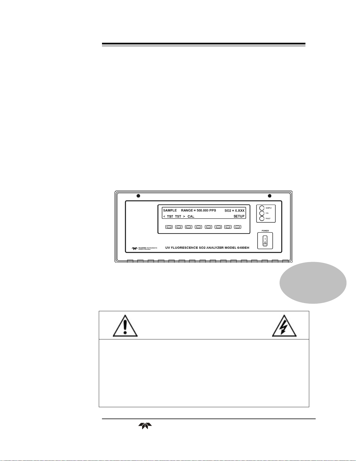
OPERATING INSTRUCTIONS FOR
Model 6400EH
UV Fluorescence SO2 Analyzer
P/N M77713
DANGER
Dependingon your application, toxic gases may be present in this monitoring
system.
Personal protective equipment may be required when servicing this instrument.
Hazardous voltages exist on certain components internally which may persist
for a time even after the power is turned off and disconnected.
Only authorized personnel should conduct maintenance and/or servicing.
Before conducting any maintenance or servicing, consult with authorized
supervisor/manager.
Teledyne Analytical Instruments
Page 2

Model 6400EH
Copyright © 2008 Teledyne Instruments/ Analytical Instruments
All Rights Reserved. No part of this manual may be reproduced, transmitted, transcribed,
stored in a retrieval system, or translated into any other language or computer language in
whole or in part, in any form or by any means, whether it be electronic, mechanical,
magnetic, optical, manual, or otherwise, without the prior written consent of Teledyne
Instruments/ Analytical Instruments, 16830 Chestnut Street, City of Industry, CA 91749-
1580.
Warranty
This equipment is sold subject to the mutual agreement that it is warranted by us free from
defects of material and of construction, and that our liability shall be limited to replacing or
repairing at our factory (without charge, except for transportation), or at customer plant at
our option, any material or construction in which defects become apparent within one year
from the date of shipment, except in cases where quotations or acknowledgements provide
for a shorter period. Components manufactured by others bear the warranty of their
manufacturer. This warranty does not cover defects caused by wear, accident, misuse,
neglect or repairs other than those performed by TI/AI or an authorized service center. We
assume no liability for direct or indirect damages of any kind and the purchaser by the
acceptance of the equipment will assume all liability for any damage which may result from
its use or misuse.
We reserve the right to employ any suitable material in the manufacture of our apparatus,
and to make any alterations in the dimensions, shape or weight of any parts, in so far as
such alterations do not adversely affect our warranty.
Important Notice
This instrument provides measurement readings to its user, and serves as a tool by which
valuable data can be gathered. The information provided by the instrument may assist the user
in eliminating potential hazards caused by his process; however, it is essential that all
personnel involved in the use of the instrument or its interface, with the process being
measured, be properly trained in the process itself, as well as all instrumentation related to it.
The safety of personnel is ultimately the responsibility of those who control process
conditions. While this instrument may be able to provide early warning of imminent
danger, it has no control over process conditions, and it can be misused. In particular, any
alarm or control systems installed must be tested and understood, both as to how they
operate and as to how they can be defeated. Any safeguards required such as locks, labels,
or redundancy, must be provided by the user or specifically requested of TI/AI at the time
the order is placed.
Therefore, the purchaser must be aware of the hazardous process conditions. The purchaser
is responsible for the training of personnel, for providing hazard warning methods and
instrumentation per the appropriate standards, and for ensuring that hazard warning devices
and instrumentation are maintained and operated properly.
Teledyne Instruments/ Analytical Instruments, the manufacturer of this instrument, cannot
accept responsibility for conditions beyond its knowledge and control. No statement
expressed or implied by this document or any information disseminated by the
manufacturer or its agents, is to be construed as a warranty of adequate safety control under
the user’s process conditions.
Teledyne Analytical Instruments ii
Page 3

UV Fluorescence SO2 Analyzer
Specific Model Information
Instrument Serial Number: _______________________
Instrument Range: _______________
Calibrated for: _______________
Background Gas: _______________
Zero Gas: _______________
Span Gas: _______________
Teledyne Analytical Instruments iii
Page 4
Model 6400EH
Safety Messages
Your safety and the safety of others is very important. We have
provided many important safety messages in this manual. Please read
these messages carefully.
A safety message alerts you to potential hazards that could hurt you
or others. Each safety message is associated with a safety alert symbol.
These symbols are found in the manual and inside the instrument. The
definition of these symbols is described below:
GENERAL WARNING/CAUTION: Refer to the instructions
for details on the specific danger. These cautions warn of
specific procedures which if not followed could cause bodily
Injury and/or damage the instrument.
CAUTION: HOT SURFACE WARNING: This warning is
specific to heated components within the instrument. Failure
to heed the warning could result in serious burns to skin and
underlying tissue.
WARNING: ELECTRICAL SHOCK HAZARD: Dangerous
voltages appear within this instrument. This warning is
specific to an electrical hazard existing at or nearby the
component or procedure under discussion. Failure to heed this
warning could result in injury and/or death from
electrocution.
Technician Symbol: All operations marked with this symbol
are to be performed by qualified maintenance personnel only.
CAUTION: THE ANALYZER SHOULD ONLY BE USED FOR THE
PURPOSE AND IN THE MANNER DESCRIBED IN
THIS MANUAL.
IF YOU USE THE ANALYZER IN A MANNER OTHER
THAN THAT FOR WHICH IT WAS INTENDED,
UNPREDICTABLE BEHAVIOR COULD RESULT
POSSIBLY ACCOMPANIED WITH HAZARDOUS
CONSEQUENCES.
Teledyne Analytical Instruments iv
Page 5

UV Fluorescence SO2 Analyzer
This manual provides information designed to guide you through
the installation, calibration operation and maintenance of your new
analyzer. Please read this manual and keep it available.
Occasionally, some instruments are customized for a particular
application or features and/or options added per customer requests.
Please check the front of this manual for any additional information in
the form of an Addendum which discusses specific information,
procedures, cautions and warnings that may be peculiar to your
instrument.
Manuals do get lost. Additional manuals can be obtained from
TI/AI at the address given in the Appendix. Some of our manuals are
available in electronic form via the internet. Please visit our website at:
www.teledyne-ai.com.
Teledyne Analytical Instruments v
Page 6

Model 6400EH
Table of Contents
List of Figures .............................................................................. ix
List of Tables ................................................................................ xi
Documentation .............................................................................. 1
1.1. Using This Manual Addendum 2
Specifications, Approvals & Warranty ........................................ 5
2.1. Specifications 5
2.2. CE Mark Compliance 6
2.3. Warranty 7
Getting Started .............................................................................. 9
3.1. Unpacking and Initial Setup 9
3.1.1. Electrical Connections: 10
3.1.1.1. External Pump 10
3.2 Pneumatic Connections 11
3.2.2 Pneumatic Connections to the 6400EH 11
3.2.2.1 Pneumatic Connections to 6400EH Basic
Configuration 11
3.2.2.2 Connections with Internal Valve Options Installed 12
3.2.3 6400EH Layout 13
3.3 Initial Operation 15
3.3.1 Warning Messages 15
3.3.2 Test Functions 15
3.3.3 Interferents for SO2 Measurements 15
Frequently Asked Questions ...................................................... 17
Optional Hardware and Software ............................................... 19
5.1 Zero/Span Valves (Option 50) 19
5.2 Internal Zero/Span Gas Generator (Option 51) 20
Teledyne Analytical Instruments vi
Page 7

UV Fluorescence SO2 Analyzer
5.3 Zero and Two Span Point Valve Option (OPT 52) 20
5.4 Hydrocarbon Kicker Option (OPT 65) 22
Operating Instructions ................................................................ 25
6.1 Warning Messages 25
6.2 Test Functions 25
6.2.1 Test Channel Output 26
6.2.2 Range Units 26
6.2.3 Using the 6400EH with a Hessen Protocol Network 26
6.2.4 Default iDAS Channels 28
6.2.5 Remote Operation Using the External Digital I/O 28
6.2.5.1 Status Outputs 28
6.2.5.2 Control Inputs 29
Calibration and Calibration Check Procedures ........................ 31
7.1 Manual Calibration with the Zero and Two Span Point
Valve Option (OPT 52) installed 31
7.2 Manual Calibration Check with the Zero and Two Span
Point Valve Option (OPT 52) installed 33
Instrument Maintenance ............................................................. 35
8.1 Maintenance Schedule 35
8.2 Predictive Diagnostics 35
Theory of Operation .................................................................... 37
9.1 The UV Light Path 37
9.1.1 The Reference Detector 38
9.1.2 Direct Measurement Interferences 38
9.2 Pneumatic Operation 39
9.2.1 Sample Gas Flow 39
9.2.2 Pneumatic Sensors 40
9.2.2.1 Sample Pressure Sensor 40
9.2.2.2 Vacuum Pressure Sensor 40
9.2.2.3 Sample Flow Calculation 40
9.3 Electronic Operation 41
Troubleshooting & Repair .......................................................... 43
Teledyne Analytical Instruments vii
Page 8

Model 6400EH
10.1.1 Fault Diagnosis with Warning Messages 43
10.1.2 Fault Diagnosis with Test Functions 43
10.2 Subsystem Checkout 43
10.2.1 Pneumatic Sensor Assembly 43
10.3 Repair Procedures 44
10.3.1 Repairing the Sample Gas Flow Control Assembly 44
10.3.2 Sensor Module Repair & Cleaning 46
10.3.2.1 Adjusting the UV Lamp (Peaking the Lamp) 47
10.3.2.2 PMT Hardware Calibration (FACTORY CAL) 49
10.4 Technical Assistance 52
Appendix A — Version Specific Software Documentation ...... 53
Appendix A-1: 6400EH Software Menu Trees, Revision C.0 54
Appendix A-2: Setup Variables For Serial I/O, Revision C.0 62
Appendix A-3: Warnings and Test Functions, Revision C.0 69
Appendix A-4: 6400EH Signal I/O Definitions, Revision C.0 72
Appendix A-5: 6400EH iDAS Functions, Revision C.0 77
Appendix A-6: Terminal Command Designators, Revision C.0 79
Appendix B - 6400EH Spare Parts List ...................................... 81
B-1: 6400EH Spare Parts List 81
B-2: Recommended Spare Parts Stocking Levels Model
6400EH 83
B-3: 6400E/EH Expendables Kit 84
Appendix C Warranty Questionnaire ......................................... 85
Appendix D - Electronic Schematics ......................................... 89
Teledyne Analytical Instruments viii
Page 9

UV Fluorescence SO2 Analyzer
List of Figures
Figure 3-1: Example of Pneumatic Connections to 6400EH
External Pump ............................................................ 12
Figure 3-2: Pneumatic Connections to 6400EH with Zero and Two
Span Point Valve Option ............................................. 12
Figure 3-3: Internal Pneumatic flow for 6400EH in Basic
Configuration .............................................................. 13
Figure 3-4: 6400EH Layout (Basic Unit – No Valve Options) ........ 14
Figure 3-5: Available Functions in the Model 6400EH ................... 16
Figure 5-1: Pneumatic Diagram of the 6400EH With Z/S Option
Installed. ..................................................................... 19
Figure 5-2: Pneumatic Diagram of the 6400EH With 2-Span Point
Option Installed ........................................................... 21
Figure 5-3: Hydrocarbon Scrubber (Kicker) – OPT 65 .................. 23
Figure 5-4: 6400EH Internal Pneumatic Diagram with
Hydrocarbon Scrubber Installed ................................. 23
Figure 9-1: UV Light Path .............................................................. 37
Figure 9-2: Pneumatic Diagram of the6400EH – Base
Configuration .............................................................. 39
Figure 9-3: 6400EH Electronic Block Diagram .............................. 41
Figure 9-4: Model 6400EH Power Distribution Block Diagram ...... 42
Figure 10-1: Flow Control Assembly ............................................. 45
Figure 10-2: Sensor Module Wiring and Pneumatic Fittings .......... 46
Figure 10-3: Shutter Assembly - Exploded View ........................... 47
Figure 10-4: Location of UV Reference Detector Potentiomete
r .... 49
Figure 10-5: Pre-Amplifier Board Layout ....................................... 50
Figure A-1: Basic Sample Display Menu ....................................... 54
Teledyne Analytical Instruments ix
Page 10

Model 6400EH
Figure A-2: Sample Display Menu - Z/S Valve Option installed .... 55
Figure A-3: Primary Setup Menu (Except iDAS) ........................... 56
Figure A-4: Primary Setup Menu (iDAS) ....................................... 57
Figure A-5: Secondary Setup Menu (COMM & VARS) ................. 58
Figure A-6: Secondary Setup Menu (COMM Menu with Ethernet
Card) .......................................................................... 59
Figure A-7: Secondary Setup Menu - HESSEN Submenu ............ 60
Figure A-8: Secondary Setup Menu (DIAG) .................................. 61
Teledyne Analytical Instruments x
Page 11

UV Fluorescence SO2 Analyzer
List of Tables
Table 2-1: Model 6400EH Basic Unit Specifications ....................... 5
Table 3-1: Inlet / Outlet Connector Nomenclature ......................... 11
Table 3-2: Possible Warning Messages at Start-Up ...................... 15
Table 5-1: Two-Point Span Valve Operating States ...................... 22
Table 6-1: Additional 6400EH Warning Messages ........................ 25
Table 6-2: Additional 6400EH Test Functions ............................... 25
Table 6-3: Additional 6400 EH Test Parameters Available for
Analog Output A3 ......................................................... 26
Table 6-4: 6400EH Default Hessen Status Bit Assignments ......... 27
Table 6-5: Status Output Signals ................................................... 28
Table 6-6: Control Input Signals .................................................... 30
Table 8-1: Predictive Uses for Test Functions ............................... 35
Table 10-1: Warning Messages - Indicated Failures ..................... 43
Table 10-2: Test Functions - Possible Causes for Out-Of-Range
Values ......................................................................... 43
Table 10-3: Example of HVPS Power Supply Outputs .................. 48
Table A-1: 6400EH Setup Variables, Revision C.0 ....................... 62
Table A-2: 6400EH Warning Messages, Revision C.0 .................. 69
Table A-3: 6400EH Test Functions, Revision C.0 ......................... 70
Table A-4: 6400EH Signal I/O Definitions, Revision C.0 ............... 72
Table A-5: 6400EH DAS Trigger Events, Revision C.0 ................. 77
Table A-6: 6400EH iDAS Functions, Revision C.0 ........................ 77
Table A-7: Terminal Command Designators, Revision C.0 ........... 79
Table B-1: Model 6400EH Spare Parts List ................................... 81
Table D-1: List of Included Electronic Schematics ........................ 89
Teledyne Analytical Instruments xi
Page 12
Model 6400EH
DANGER
COMBUSTIBLE GAS USAGE
This is a general purpose instrument designed for use in a
non-hazardous area. It is the customer's responsibility to
ensure safety especially when combustible gases are being
analyzed since the potential of gas leaks always exist.
The customer should ensure that the principles of operating
this equipment are well understood by the user. Misuse of
this product in any manner, tampering with its components,
or unauthorized substitution of any component may
adversely affect the safety of this instrument.
WARNING
Since the use of this instrument is beyond the control of
Teledyne Analytical Instruments, referred as TAI, no
responsibility by TAI, its affiliates, and agents for damage or
injury from misuse or neglect of this equipment is implied or
assumed.
Teledyne Analytical Instruments xii
Page 13

UV Fluorescence SO2 Analyzer Documentation
Documentation
Note: Throughout this manual, words printed in capital, bold letters,
such as SETUP or ENTR represent messages as they appear
on the analyzer’s front panel display
Note: The flowcharts in this manual contain typical
representations of the analyzer’s display during the
various operations being described. These representations
are not intended to be exact and may differ
slightly from the actual display of your instrument.
Thank you for purchasing the Model 6400EH UV Fluorescence
SO2 Analyzer.
The electronic manual is in Adobe® Systems Inc. “Portable
Document Format”. The Adobe® Acrobat Reader® software, which is
necessary to view these files, can be downloaded for free from the
internet at http://www.adobe.com/.
The electronic version of the manual has many advantages:
Keyword and phrase search feature
Figures, tables and internet addresses are linked so that clicking on
the item will display the associated feature or open the website.
A list of chapters and sections as well as thumbnails of each page
are displayed to the left of the text.
Entries in the table of contents are linked to the corresponding
locations in the manual.
Ability to print sections (or all) of the manual
Additional documentation for the Model 6400EH UV Fluorescence
SO2 Analyzer is available from Teledyne Instruments’ website at
http://www.teledyne-ai.com/manuals/
Teledyne Analytical Instruments 1
Page 14

Documentation Model 6400EH
APICOM software manual
Multi-drop manual
DAS Manual
1.1. Using This Manual Addendum
This manual addendum has the same overall structure as that of the
6400E operator’s manual, to simplify referring between the two. The
manual has the following sections:
Table of Contents:
Outlines the contents of the addendum in the order the information
is presented. This is a good overview of the topics covered in the
manual. There is also a list of tables, a list of figures and a list of
appendices.
Specifications and Warranty
This section contains a list of the analyzer’s performance
specifications, a description of the conditions and configuration under
which EPA equivalency was approved and Teledyne Instrument’s
warranty statement.
Getting Started:
A concise set of instructions for setting up, installing and running
your analyzer for the first time.
FAQ:
Answers to the most frequently asked questions about operating the
analyzer.
Optional Hardware & Software:
A description of optional equipment to add functionality to your
analyzer.
Operation Instructions:
This section includes step by step instructions for operating the
analyzer and using its various features and functions.
Calibration Procedures:
Teledyne Analytical Instruments 2
Page 15

UV Fluorescence SO2 Analyzer Documentation
General information and step by step instructions for calibrating
your analyzer.
Instrument Maintenance:
Description of preventative maintenance procedures that should be
regularly performed on you instrument to assure good operating
condition.
Theory of Operation:
This section describes the aspects of 6400EH operation that differ
from the 6400E manual.
Maintenance & Troubleshooting Section:
This section includes pointers and instructions for diagnosing
problems that are specific to the 6400EH. The 6400E manual has a more
complete troubleshooting section, most of which also applies to the
6400EH.
Appendices:
For easier access and better updating, some information has been
separated out of the manual and placed in a series of appendices at the
end of this addendum. These include: software menu trees, warning
messages, definitions of iDAS & serial I/O variables, spare parts list,
repair questionnaire, interconnect listing and drawings, and electronic
schematics.
Teledyne Analytical Instruments 3
Page 16

Documentation Model 6400EH
Teledyne Analytical Instruments 4
Page 17
UV Fluorescence SO2 Analyzer Specifications/Warranty
Specifications, Approvals & Warranty
2.1. Specifications
Table 2-1: Model 6400EH Basic Unit Specifications
Min/Max Range
(Physical Analog Output)
Measurement Units ppm, mg/m3 (user selectable)
Zero Noise1 0.05 ppm rms
Span Noise1 < 0.5% of reading (above 50 ppm)
Lower Detectable Limit2 0.1 ppm rms
Zero Drift (24 hours) < 1 ppm
Zero Drift (7 days) < 2 ppm
Span Drift (7 Days) < 0.5% FS
Linearity 1 % of full scale
Precision 0.5% of reading1
Temperature Coefficient < 0.1% per oC
Voltage Coefficient < 0.05% per V
Lag Time1 5 sec
Rise/Fall Time1 95% in < 30 sec
Sample Flow Rate 700 cm3/min. ±10%
Temperature Range 5-40oC
Humidity Range 0 - 95% RH, non-condensing
Dimensions H x W x D 7" x 17" x 23.5" (178 mm x 432 mm x 597 mm)
Weight, Analyzer
(Basic Configuration)
Weight, Pump Pack 16 lbs (7 kg)
AC Power Rating
Environmental
Analog Outputs Three (3) Outputs
In 1 ppb increments from 10ppm to 5,000 ppm, dual
ranges or auto ranging
45 lbs (20.5 kg) w/internal pump
100 V, 50/60 Hz (3.25A); 115 V, 60 Hz (3.0 A);
220 – 240 V, 50/60 Hz (2.5 A)
Installation category (over-voltage category) II; Pollution
degree 2
Teledyne Analytical Instruments 5
Page 18

Specifications/Warranty Model 6400EH
100 mV, 1 V, 5 V, 10 V, 2-20 or 4-20 mA isolated
Analog Output Ranges
Analog Output Resolution 1 part in 4096 of selected full-scale voltage
Status Outputs 8 Status outputs from opto-isolators
Control Inputs 6 Control Inputs, 3 defined, 3 spare
Serial I/O
Certifications
1 As defined by the USEPA.
2 Defined as twice the zero noise level by the USEPA.
current loop.
All Ranges with 5% Under/Over Range
One (1) RS-232; One (1) RS-485 (2 connecters in
parallel)
Baud Rate : 300 – 115200: Optional Ethernet Interface
EN61326 (1997 w/A1: 98) Class A,
FCC Part 15 Subpart B Section 15.107 Class A,
ICES-003 Class A (ANSI C63.4 1992) & AS/NZS 3548
(w/A1 & A2; 97) Class A.
IEC 61010-1:90 + A1:92 + A2:95,
2.2. CE Mark Compliance
Emissions Compliance
The TAI UV Fluorescence SO2 Analyzer 6400EH was tested and
found to be fully compliant with:
EN61326 (1997 w/A1: 98) Class A, FCC Part 15 Subpart B Section
15.107 Class A, ICES-003 Class A (ANSI C63.4 1992) & AS/NZS
3548 (w/A1 & A2; 97) Class A.
Tested on 21 February 2003 - 08 March 2003 at CKC Laboratories,
Inc., Report Number CE03-021 A.
Safety Compliance
The TAI UV Fluorescence SO
found to be fully compliant with:
I EC 61010-1:90 + A1:92 + A2:95,
Issued by CKC Laboratories on 4 April 2003, Report Number WO-
80146.
Analyzer 6400EH was tested and
2
Teledyne Analytical Instruments 6
Page 19

UV Fluorescence SO2 Analyzer Specifications/Warranty
2.3. Warranty
Warranty Policy (02024d)
Prior to shipment, TAI equipment is thoroughly inspected and
tested. Should equipment failure occur, TAI assures its customers that
prompt service and support will be available.
Coverage
After the warranty period and throughout the equipment lifetime,
TAI stands ready to provide on-site or in-plant service at reasonable
rates similar to those of other manufacturers in the industry. All
maintenance and the first level of field troubleshooting is to be
performed by the customer.
NON-TAI MANUFACTURED EQUIPMENT
Equipment provided but not manufactured by TAI is warranted and
will be repaired to the extent and according to the current terms and
conditions of the respective equipment manufacturers warranty.
GENERAL
During the warranty period, TAI warrants each Product
manufactured by TAI to be free from defects in material and
workmanship under normal use and service. Expendable parts are
excluded.
If a Product fails to conform to its specifications within the
warranty period, TAI shall correct such defect by, in TA's discretion,
repairing or replacing such defective Product or refunding the purchase
price of such Product.
The warranties set forth in this section shall be of no force or effect
with respect to any Product: (i) that has been altered or subjected to
misuse, negligence or accident, or (ii) that has been used in any manner
other than in accordance with the instruction provided by TAI, or (iii)
not properly maintained.
THE WARRANTIES SET FORTH IN THIS SECTION AND THE REMEDIES
THEREFORE ARE EXCLUSIVE AND IN LIEU OF ANY IMPLIED
WARRANTIES OF MERCHANTABILITY, FITNESS FOR PARTICULAR
PURPOSE OR OTHER WARRANTY OF QUALITY, WHETHER EXPRESSED
OR IMPLIED. THE REMEDIES SET FORTH IN THIS SECTION ARE THE
EXCLUSIVE REMEDIES FOR BREACH OF ANY WARRANTY CONTAINED
HEREIN. TAI SHALL NOT BE LIABLE FOR ANY INCIDENTAL OR
Teledyne Analytical Instruments 7
Page 20

Specifications/Warranty Model 6400EH
CONSEQUENTIAL DAMAGES ARISING OUT OF OR RELATED TO THIS
AGREEMENT OF TAI'S PERFORMANCE HEREUNDER, WHETHER FOR
BREACH OF WARRANTY OR OTHERWISE
Terms and Conditions
All units or components returned to TAI should be properly packed
for handling and returned freight prepaid to the nearest designated
Service Center. After the repair, the equipment will be returned, freight
prepaid.
Teledyne Analytical Instruments 8
Page 21
UV Fluorescence SO2 Analyzer Getting Started
Getting St arted
3.1. Unpacking and Initial Setup
CAUTION: TO AVOID PERSONAL INJURY, ALWAYS USE TWO
PERSONS TO LIFT AND CARRY THE MODEL
6400EH.
1. Inspect the received packages for external shipping damage. If
damaged, please advise the shipper first, then TAI.
2. Included with your analyzer is a printed record of the final
performance characterization performed on your instrument at
the factory. This record is an important quality assurance and
calibration record for this instrument. It should be placed in the
quality records file for this instrument.
3. Carefully remove the top cover of the analyzer and check for
internal shipping damage.
Remove the set screw located in the top, center of the rear
panel
Remove the screws fastening the top cover to the unit (four
per side).
Lift the cover straight up.
Note: Printed circuit assemblies (PCAs) are sensitive to electro-
static discharges too small to be felt by the human nervous
system. Failure to use ESD protection when working with
electronic assemblies will void the instrument warranty.
See Chapter 12 of the 6400E Manual (P/N 04515) for more
information on preventing ESD damage.
Teledyne Analytical Instruments 9
Page 22
Getting Started Model 6400EH
CAUTION: NEVER DISCONNECT ELECTRONIC CIRCUIT
BOARDS, WIRING HARNESSES OR ELECTRONIC
SUBASSEMBLIES WHILE THE UNIT IS UNDER
POWER.
4. Inspect the interior of the instrument to make sure all circuit
boards and other components are in good shape and properly
seated.
5. Check the connectors of the various internal wiring harnesses
and pneumatic hoses to make sure they are firmly and properly
seated.
6. Verify that all of the optional hardware ordered with the unit has
been installed. These are checked on the paperwork
accompanying the analyzer.
3.1.1. Electrical Connections:
For full details on the electrical connections of the 6400EH, please
refer to Chapter 3 in the 6400E user’s manual.
3.1.1.1. External Pump
The 6400EH is equipped with an external pneumatic pump. This
pump is powered separately from the instrument via it’s own power
cord. The pump has no ON/OFF switch and should begin operating as
soon as it is plugged into a live power supply.
CAUTION: CHECK THE VOLTAGE / FREQUENCY LABEL ON
THE REAR PANEL OF THE INSTRUMENT AND ON
THE EXTERNAL PUMP FOR COMPATIBILITY WITH
THE LOCAL POWER. DO NOT PLUG IN EITHER THE
ANALYZER OR THE PUMP UNLESS THE VOLTAGES
OR FREQUENCIES ARE CORRECT.
POWER CONNECTION MUST HAVE A FUNCTIONING
GROUND CONNECTION. DO NOT DEFEAT THE
GROUND WIRE ON POWER PLUG.
TURN OFF ANALYZER POWER BEFORE
DISCONNECTING OR CONNECTING ELECTRICAL
SUBASSEMBLIES.
DO NOT OPERATE WITH COVER OFF.
Teledyne Analytical Instruments 10
Page 23

UV Fluorescence SO2 Analyzer Getting Started
3.2 Pneumatic Connections
3.2.2 Pneumatic Connections to the 6400EH
Note: To prevent dust from getting into the analyzer, it was
shipped with small plugs inserted into each of the
pneumatic fittings on the rear panel. Make sure that all dust
plugs are removed before attaching exhaust
and supply gas lines.
Table 3-1: Inlet / Outlet Connector Nomenclature
REAR PANEL
LABEL
Sample Connects the sample gas to the analyzer. When operating the analyzer without
zero/span option, this is also the inlet for any calibration gases.
Exhaust Connect an exhaust gas line to this port to the inlet of the external pump.
Zero Air
On Units with zero/span valve option installed, this port connects the zero air gas or the
zero air cartridge to the analyzer.
FUNCTION
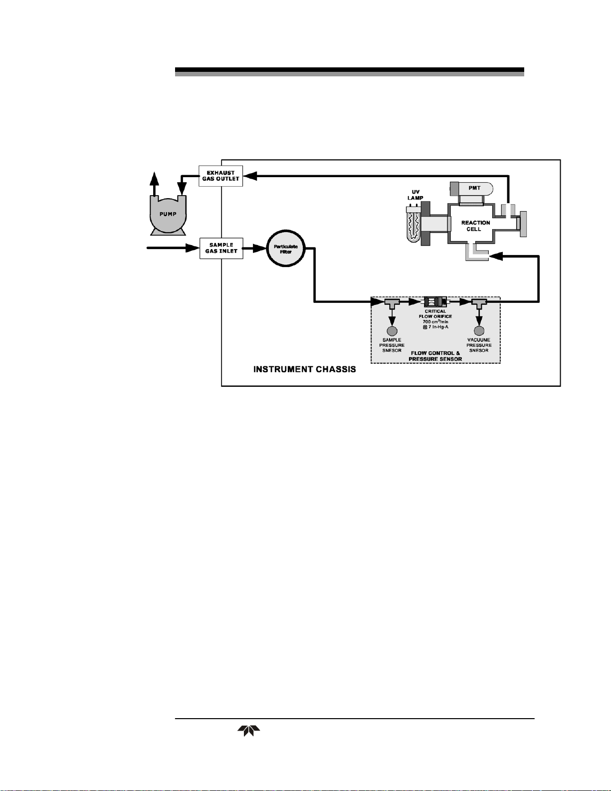
Figure 3-5 of the 6400E Manual shows the internal pneumatic flow
of the 6400E in its standard configuration. For a diagram of the internal
pneumatic flow of the 6400EH, see Figure 3-2 of this manual.
3.2.2.1 PNEUMATIC CONNECTIONS TO 6400EH BASIC CONFIGURATION
The pneumatic connections for the 6400EH analyzer in its basic
configuration are nearly identical to those described the 6400E Manual
in Section 3.1.2.2 except that the 6400EH has an external pump.
Therefore:
A pneumatic line of ¼” PTEF must be attached between the
analyzer’s exhaust port and the inlet port of the pump.
The exhaust from must be vented outside the shelter or immediate
area surrounding the instrument using a maximum of 10 meters of
1/4” PTFE tubing.
Teledyne Analytical Instruments 11
Page 24
Getting Started Model 6400EH
Figure 3-1: Example of Pneumatic Connections to 6400EH
External Pump
This change is true for all configurations and variations of the
6400EH.
3.2.2.2 CONNECTIONS WITH INTERNAL VALVE OPTIONS INSTALLED
There is no IZS option available for the 6400EH .
An additional valve option (Option 52 - Zero & Two Span Points)
is available on the 6400EH. The pneumatic set up for this option
is:
Figure 3-2: Pneumatic Connections to 6400EH with Zero and Two
Span Point Valve Option
Teledyne Analytical Instruments 12
Page 25
UV Fluorescence SO2 Analyzer Getting Started
3.2.3 6400EH Layout
Figure 3-3: Internal Pneumatic flow for 6400EH in Basic
Configuration
Teledyne Analytical Instruments 13
Page 26
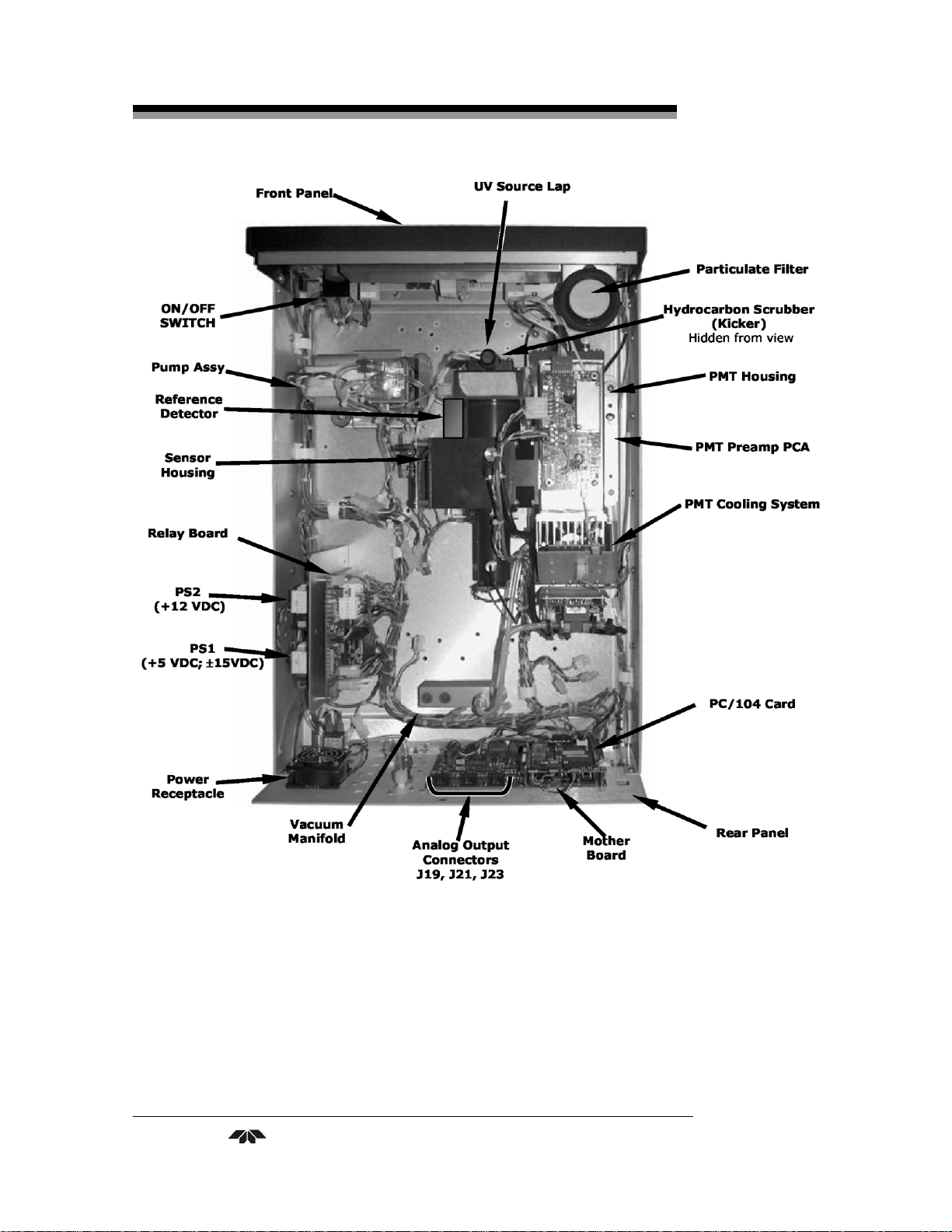
Getting Started Model 6400EH
Figure 3-4: 6400EH Layout (Basic Unit – No Valve Options)
Teledyne Analytical Instruments 14
Page 27

UV Fluorescence SO2 Analyzer Getting Started
3.3 Initial Operation
With the following exceptions, the operation of the 6400EH is
nearly identical to that of the 6400E. Please refer to the 6400E User’s
Manual, Chapter 3, for details on initial operation, including common
warning messages, functional checkout of the instrument, initial
calibration and common interferents for the 6400EH.
3.3.1 Warning Messages
Please refer to the 6400E User’s Manual, Chapter 3, for a complete
listing of warnings for the 6400EH. The following table lists warnings
that differ in the 6400EH from those described in the 6400E manual.
Table 3-2: Possible Warning Messages at Start-Up
MESSAGE MEANING
Vacuum Pressure Warning
The vacuum pressure reading is out of it’s allowed range. The pump
may have failed, or the instrument may have a leak or obstruction in
the flow path.
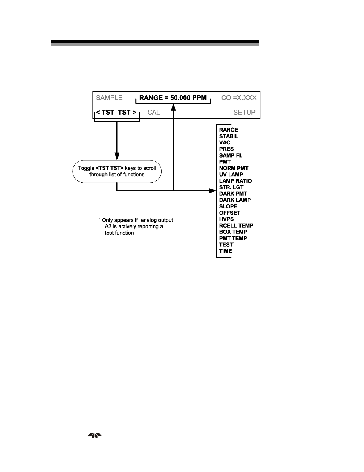
3.3.2 Test Functions
Check to make sure that the analyzer is functioning within
allowable operating parameters As described in Section 3.2.4 of the
6400E Manual (P/N 04515). The available test functions for the 6400EH
is shown in Figure 3-5.
3.3.3 Interferents for SO
2 Measurements
Hydrocarbons are a significant interferent for UV fluorescent SO2
measurements, however, the typical 6400EH application does not have
hydrocarbons in the sample stream. Therefore, in order to reduce cost to
the customer, the 6400EH in its standard configuration does not include
a hydrocarbon kicker/scrubber.
If your application includes hydrocarbons in the sample gas stream,
it is very important that they be removed from the sample gas prior to
them entering the analyzer’s sample chamber. A hydrocarbon Kicker
Option (OPT 65) package (see Section 5 below) is available for this
purpose.
Teledyne Analytical Instruments 15
Page 28
Getting Started Model 6400EH
Figure 3-5: Available Functions in the Model 6400EH
Teledyne Analytical Instruments 16
Page 29

UV Fluorescence SO2 Analyzer FAQ
Frequently Asked Questions
Q: How long does the sample pump last?
A: The sample pump should last about one year and the pump
diaphragms should to be replaced annually or when
necessary.
To determine if the diaphragm on a 6400EH needs replacing check
the VAC test function (instead of the PRES function as described in the
6400E Manual). If the VAC value is > 10 in-Hg-A, the diaphragm should
be replaced.
Teledyne Analytical Instruments 17
Page 30

FAQ Model 6400EH
Teledyne Analytical Instruments 18
Page 31

UV Fluorescence SO2 Analyzer Optional Hardware/Software
Optional Hardware and Software
With the following additions, changes and exceptions, the options
listed in Chapter 5 of the 6400E Manual are also available for the
6400EH.
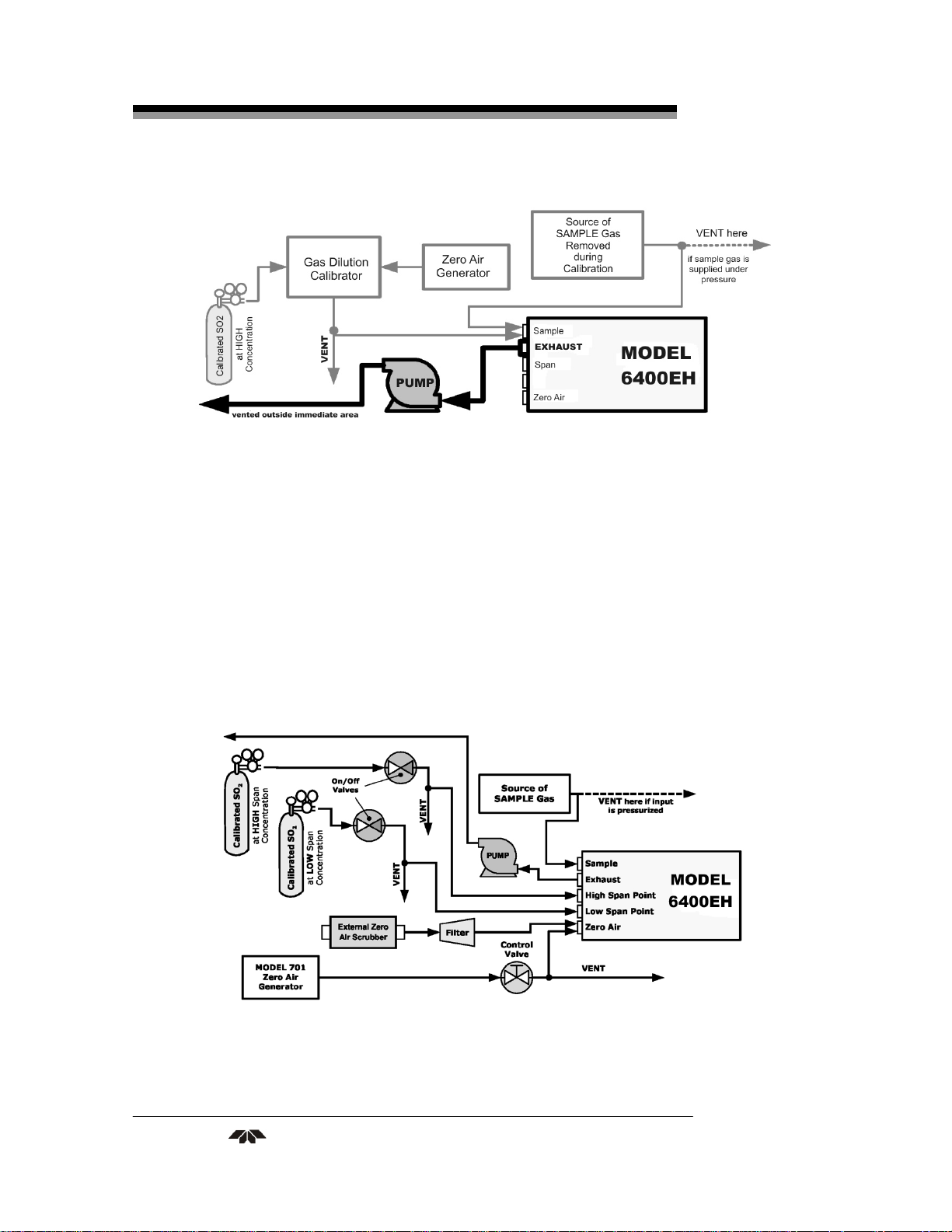
5.1 Zero/Span Valves (Option 50)
The 6400EH zero/span valve option is identical to that of the
6400E in respect to operation and valve states (see Table 5-1 of the
6400E Manual). The internal pneumatic connections are slightly
different.
Figure 5-1: Pneumatic Diagram of the 6400EH With Z/S Option
Installed.
Teledyne Analytical Instruments 19
Page 32

Optional Hardware/Software Model 6400EH
5.2 Internal Zero/Span Gas Generator (Option 51)
The IZS valve option (OPT 51) is not available for the 6400EH.
5.3 Zero and Two Span Point Valve Option (OPT 52)
This option includes a special set of valves that allows two separate
SO
mixtures to enter the analyzer from two independent sources.
2
Typically these two gas mixtures will come from two, separate,
pressurized bottles of certified calibration gas: one mixed to produce a
SO2 concentration equal to the expected span calibration value for the
application and the other mixed to produce a concentration at or near the
midpoint of the intended measurement range. Individual gas inlets,
labeled HIGH SPAN and LOW SPAN are provided at the back on the
analyzer.
The valves allow the user to switch between the two sources via
keys on the front panel or from a remote location by way of either the
analyzer’s digital control inputs or by sending commands over it’s serial
I/O port(s). The pneumatic diagram for instruments with the zero and
two span point valve option (OPT 52) is shown in Figure 5-2.
Note: The analyzer’s software only allows the SLOPE and
OFFSET to be calculated when sample is being
routed through the HIGH SPAN inlet.
The LOW SPAN gas is for midpoint reference checks only.
Teledyne Analytical Instruments 20
Page 33

UV Fluorescence SO2 Analyzer Optional Hardware/Software
Figure 5-2: Pneumatic Diagram of the 6400EH With 2-Span Point
Option Installed
Table 5-1 describes the state of each valve during the analyzer’s
various operational modes.
Teledyne Analytical Instruments 21
Page 34

Optional Hardware/Software Model 6400EH
Table 5-1: Two-Point Span Valve Operating States
MODE VALVE CONDITION
SAMPLE
ZERO
CAL
HIGH
SPAN
CAL
LOW
SPAN
CHECK
Sample/Cal
Zero Gas Valve Closed to ZERO AIR inlet
High Span Valve Closed to HIGH SPAN inlet
Low Span Valve Closed to LOW SPAN inlet
Sample/Cal Closed to SAMPLE inlet
Zero Gas Valve
High Span Valve Closed to HIGH SPAN inlet
Low Span Valve Closed to LOW SPAN inlet
Sample/Cal Closed to SAMPLE inlet
Zero Gas Valve Closed to ZERO AIR inlet
High Span Valve
Low Span Valve Closed to LOW SPAN inlet
Sample/Cal Closed to SAMPLE inlet
Zero Gas Valve Closed to ZERO AIR inlet
High Span Valve Closed to HIGH SPAN inlet
Low Span Valve
Open to SAMPLE inlet
Open to ZERO AIR inlet
Open to HIGH SPAN inlet
Open to LOW SPAN inlet
5.4 Hydrocarbon Kicker Option (OPT 65)
This option is specifically designed for those applications where
hydrocarbons are present in the sample gas stream. It includes an
internal, scrubber consisting of a tube of a specialized plastic that
absorbs hydrocarbons very well located within an outer flexible plastic
tube shell.
As gas flows through the inner tube, hydrocarbons are absorbed
into the membrane walls and transported through the membrane wall and
into the hydrocarbon free, purge gas flowing through the outer tube (see
Figure 5-3). This process is driven by the hydrocarbon concentration
gradient between the inner and outer of the tubes.
Teledyne Analytical Instruments 22
Page 35

UV Fluorescence SO2 Analyzer Optional Hardware/Software
Figure 5-3: Hydrocarbon Scrubber (Kicker) – OPT 65
The scrubbed air from the inner tube is returned to be used as the
purge gas in the outer tube after it passes through the analyzers reaction
cell. This means that when the analyzer is first started, the concentration
gradient between the inner and outer tubes is small and the scrubber’s
efficiency is relatively low. When the instrument is turned on after
having been off for more than 30 minutes, it takes a certain amount of
time for the gradient to become large enough for the scrubber to
adequately remove hydrocarbons from the sample air.
Figure 5-4: 6400EH Internal Pneumatic Diagram with
Hydrocarbon Scrubber Installed
Teledyne Analytical Instruments 23
Page 36

Optional Hardware/Software Model 6400EH
Teledyne Analytical Instruments 24
Page 37

UV Fluorescence SO2 Analyzer Operating Instructions
Operating Instructions
6.1 Warning Messages
Please refer to the 6400E User’s Manual, Chapter 3, for a complete
listing of warnings for the 6400EH. The following table lists warnings
that differ in the 6400EH from those described in the 6400E manual.
Table 6-1: Additional 6400EH Warning Messages
MESSAGE MEANING
The vacuum pressure reading is out of its allowed
Vacuum Pressure Warning
range. The pump may have failed, or the instrument
may have a leak or obstruction in the flow path.
6.2 Test Functions
Please refer to the 6400E Manual, Chapter 6, for a complete list of
test functions for the 6400EH. The following table lists test functions
that are in addition to or differ from those listed there.
Table 6-2: Additional 6400EH Test Functions
DISPLAY PARAMETER UNITS DESCRIPTION
The actual pressure measured on the vacuum side
VAC
PRES
Vacuum
Pressure
Sample GAS
Pressure
In-Hg-A
in-Hg-A
of the 6400EH’s critical flow orifice. This is the
pressure of the gas in the instrument’s sample
chamber.
The current pressure of the sample gas as it enters
the sample inlet at the back of the analyzer, but
upstream of the critical flow orifice and before the
gas enters the reaction cell.
Teledyne Analytical Instruments 25
Page 38

Operating Instructions Model 6400EH
6.2.1 Test Channel Output
When activated, output channel A3 can be used to report one of the
test functions viewable from the SAMPLE mode display. To activate the
A3 channel and select a test function, follow instructions in Section
6.9.10 of the 6400E Manual.
The following table lists test functions that are in addition to or
differ from those listed in Table 6-14 of the 6400E Manual.
Table 6-3: Additional 6400 EH Test Parameters Available for Analog
Output A3
TEST CHANNEL TEST PARAMETER RANGE
VACUUM PRESSURE
0-40 in-Hg-A
6.2.2 Range Units
The 6400EH only displays concentrations in parts per million (106
mols per mol, PPM) or milligrams per cubic meter (mg/m3, MGM).
NOT AVAILABLE: Parts per billion (10
9
mols per mol, PPB)
and micrograms per cubic meter (µg/m3, UGM).
To change the concentration units of the 6400EH follow the
instructions found in Section 6.7.7 of the 6400E Manual.
6.2.3 Using the 6400EH with a Hessen Protocol Network
The set up and use of the 6400EH in Hessen protocol networks is
the sane as described in Section 6.12.4 of the M1 00E Manual (P/N
04515) except that there are minor differences in the status flags. The
following table supercedes Table 6-27 of the 6400E Manual.
Teledyne Analytical Instruments 26
Page 39

UV Fluorescence SO2 Analyzer Operating Instructions
Table 6-4: 6400EH Default Hessen Status Bit Assignments
STATUS FLAG NAME DEFAULT BIT ASSIGNMENT
WARNING FLAGS
SAMPLE FLOW WARNING 0001
PMT DET WARNING 0002
UV LAMP WARNING 0002
HVPS WARNING 0004
DARK CAL WARNING 0008
RCELL TEMP WARNING 0010
PMT TEMP WARNING 0040
INVALID CONC 0080
OPERATIONAL FLAGS
In Manual Calibration Mode 0200
In Zero Calibration Mode 0400
In Low Span Calibration Mode 0800
In Span Calibration Mode 0800
UNITS OF MEASURE FLAGS
UGM1 0000
MGM 2000
PPB1 4000
PPM 6000
SPARE/UNUSED BITS 0020, 0100, 8000
UNASSIGNED FLAGS
Box Temp Warning System Reset
Sample Press Warning Front Panel Warning
Vacuum Press Warning Analog Cal Warning
Rear Board Not Detected Cannot Dyn Zero
Relay Board Warning Cannot Dyn Span
1
Although assigned flags, these units are not available on the 6400EH
Teledyne Analytical Instruments 27
Page 40

Operating Instructions Model 6400EH
6.2.4 Default iDAS Channels
The default Data Channels included in the 6400EH analyzer’s
software include the CONC, PNUMT & CALDAT channels. The FAST &
DETAIL preset channels are not included.
6.2.5 Remote Operation Using the External Digital I/O
6.2.5.1 STATUS OUTPUTS
The function and pin assignment5s for the 6400EH digital status
outputs are:.
Table 6-5: Status Output Signals
STATUS
CONNECTOR
PIN NUMBER
1
2
3
4
5
6
7
8
D
+
1
SYSTEM OK
CONC VALID
HIGH RANGE
ZERO CAL
HIGH SPAN CAL
DIAG MODE
LOW SPAN CAL
SPARE
EMITTER BUS
SPARE
DC POWER
STATUS
DEFINITION
CONDITION
ON if no faults are present.
OFF any time the
as during calibration or when other faults exist
possibly invalidating the current concentration
measurement (example: sample flow rate is outside
of acceptable limits).
ON if concentration measurement is valid.
ON if unit is in high range of the AUTO Range Mode
ON whenever the instrument’s ZERO point is being
calibrated.
ON whenever the instrument is set for DUAL or
AUTO reporting range
mode an it’s high range span point is being calibrated
.
ON whenever the instrument is in DIAGNOSTIC
mode
ON whenever the instrument is set for DUAL or
AUTO reporting range mode an it’s lows range span
point is being calibrated .
The emitters of the transistors on pins 1-8 are bussed
together.
+ 5 VDC, 300 mA source (combined rating with
Control Output, if used).
HOLD OFF feature is active, such
Teledyne Analytical Instruments 28
Page 41

UV Fluorescence SO2 Analyzer Operating Instructions
STATUS
CONNECTOR
PIN NUMBER1
1
Located on Rear Panel
6.2.5.2 CONTROL INPUTS
STATUS
DEFINITION
Digital Ground
CONDITION
The ground level from the analyzer’s internal DC
power supplies
Figure 6-1: Control Input Connector
Teledyne Analytical Instruments 29
Page 42

Operating Instructions Model 6400EH
Table 6-6: Control Input Signals
INPUT # STATUS DEFINITION ON CONDITION
A
B
C
D, E & F
REMOTE ZERO CAL
REMOTE
HIGH SPAN CAL
REMOTE
LO SPAN CAL
SPARE
The analyzer is placed in Zero Calibration mode. The mode field of the
display will read ZERO CAL R.
If the instrument is set for DUAL or AUTO reporting rang mode,
activating this input causes the analyzer to enter high range span
calibration mode. The mode field of the display will read SPAN CAL R.
The analyzer is placed in low span calibration mode as part of
performing a low span (midpoint) calibration. The mode field of the
display will read LO CAL R.
U
+
Digital Ground
External Power input
5 VDC output
The ground level from the analyzer’s internal DC power supplies
(same as chassis ground)
Input pin for +5 VDC required to activate pins A – F.
Internally generated 5V DC power. To activate inputs A – F, place a
jumper between this pin and the “U” pin. The maximum amperage
through this port is 300 mA (combined with the analog output supply, if
used).
Teledyne Analytical Instruments 30
Page 43

UV Fluorescence SO2 Analyzer Calibration and Check
Calibration and Calibration Check Procedures
Calibration procedures for the 6400EH are the same as those for the
6400E. One exception to this statement is that the 6400EH has a special
valve option, Zero and Two Span Point Valve Option - OPT 52 (See
Section 5.1), that allows a mid-span point be checked.
7.1 Manual Calibration with the Zero and Two Span
Point Valve Option (OPT 52) installed
Note: It is only possible to calibrate to the high span gas. The low
span gas is only used for calibration checks.
Zero and Span calibrations using the Zero and two Span Valve
option are similar to that described in Section 7.2, except that:
Zero air and both span gas is supplied to the analyzer through the
zero gas and span gas inlets rather than through the sample inlet.
The zero and cal operations are initiated directly and
independently with dedicated keys (CALZ & CALS)
STEP ONE: Connect the sources of zero air and span gas to the
respective ports on the rear panel (see Figure 3-2 of this manual).
STEP TWO: Set the expected SO
high span gas value:
2
Teledyne Analytical Instruments 31
Page 44

Calibration and Check Model 6400EH
STEP THREE: Perform the calibration according to the following flow
chart:
Teledyne Analytical Instruments 32
Page 45

UV Fluorescence SO2 Analyzer Calibration and Check
7.2 Manual Calibration Check with the Zero and Two
Span Point Valve Option (OPT 52) installed
Set up is identical to that shown in STEP ONE of the preceding
section. To perform the zero/span check:
Teledyne Analytical Instruments 33
Page 46

Calibration and Check Model 6400EH
Teledyne Analytical Instruments 34
Page 47

UV Fluorescence SO2 Analyzer Maintenance
Instrument Maintenance
8.1 Maintenance Schedule
There is no Internal IZS offered for the 6400EH.
8.2 Predictive Diagnostics
Because the 6400EH’s internal pneumatics are monitored in a
different manner than those of the 6400E there are some differences in
how the instruments test functions are used as predictive diagnostics.
Table 8-1 of this addendum supersedes Table 9-2 of the 6400E Manual
Table 8-1: Predictive Uses for Test Functions
TEST
FUNCTION
PRES SMPPRS
PRES SMPPRS
VAC VACUUM
IDAS
FUNCTION
CONDITION
Sample gas
pressure
upstream of the
critical flow
orifice.
Sample gas
pressure
upstream of the
critical flow
orifice.
Gas pressure
downstream of
the critical flow
orifice (e.g.
inside reaction
cell.
EXPECTED ACTUAL
Constant within
atmospheric
changes
Constant within
atmospheric
changes
Constant within
atmospheric
changes
BEHAVIOR
Slowly
increasing
Slowly
decreasing
Slowly
increasing
Slowly
decreasing
Fluctuating
INTERPRETATION
• Flow path is clogging up.
- Check critical flow
orifice & sintered filter.
- Replace particulate
filter
• Developing leak in
pneumatic system to
vacuum (developing
valve failure)
• Flow path is clogging up.
- Check critical flow
orifice & sintered filter.
- Replace particulate
filter
• Developing leak in
pneumatic system to
vacuum (developing
valve failure)
• Developing leak in
pneumatic system
Teledyne Analytical Instruments 35
Page 48

Maintenance Model 6400EH
TEST
FUNCTION
SAMP FL SMPFLW
DRK PMT DRKPMT
SO2
Concentration
LAMP RATIO LAMPR
FUNCTION
CONC1
IDAS
CONDITION
Standard
Operation
PMT output
when UV Lamp
shutter closed
Standard
configuration at
span
Standard
Operation
EXPECTED ACTUAL
Stable
Constant within
±20 of checkout value
stable for
constant
concentration
Stable and near
100%
BEHAVIOR
Slowly
Decreasing
Significantly
increasing
Decreasing
over time
Fluctuating • Leak in gas flow path.
Fluctuating
or Slowly
increasing
Slowly
deceasing
INTERPRETATION
• Flow path is clogging up.
- Check critical flow
orifice & sintered filter.
- Replace particulate
filter
• PMT cooler failure
• Shutter Failure
• Drift of instrument
response; UV Lamp
output is excessively
low.
• UV detector wearing out
• UV source Filter
developing pin holes
• UV detector wearing out
• Opaque oxides building
up on UV source Filter
• UV lamp aging
Teledyne Analytical Instruments 36
Page 49

UV Fluorescence SO2 Analyzer Theory of Operation
Theory of Operation
9.1 The UV Light Path
The UV light path of the 6400EH is similar to that of the 6400E
(see Section 10.2 of the 6400E Manual). The main differences between
the 6400EH and the 6400E are:
The location of the reference detector (See Section 9.1.1 of this
addendum).
The methods used to reject for certain measurement interferents is
different (see Section 9.1.2 of this manual).
Figure 9-1: UV Light Path
Teledyne Analytical Instruments 37
Page 50

Theory of Operation Model 6400EH
9.1.1 The Reference Detector
A vacuum diode UV detector that converts UV light to a DC
current is used to measure the intensity of the excitation UV source
lamp. The location of the 6400EH reference detector differs from that of
the 6400E.
On the 6400E this detector is located directly across the reaction cell
from the lamp where it can measure the output of the lamp
directly. Because the 6400E is designed to measure relatively
low concentrations of SO
, enough of the lamp’s 214 nm source
2
light makes it through the reaction cell to get a reliable reading.
On the 6400EH the detector is located between the UV lamp and the
reaction cell and to the side. A beam splitter reflects a portion of
the lamp output 90 degrees, through a window and onto the
detector. This arrangement is required because nearly all of 214
nm UV source light entering the reaction cell is absorbed by the
higher concentrations of SO2 typically measured by the 6400EH.
A window transparent to UV light provides an air-proof seal that
prevents ambient gas from contaminating the sample chamber.
9.1.2 Direct Measurement Interferences
The most common source of interference when measuring SO2 is
from other gases that fluoresce in a similar fashion to SO2 when exposed
to UV Light. The most significant of these are:
A class of hydrocarbons called poly-nuclear aromatics (PNA) of
which xylene and naphthalene are two prominent examples.
Nitric oxide (NO), which fluoresces in a spectral range near to SO
.
2
For critical applications where high levels of NO are expected an
optional 360 nm optical filter is available that improves the rejection
of NO (contact customer service for more information).
The methods by which the Model 6400EH rejects interference for
these substances differs from the M1 00E as follows.
Since the typical application for which the 6400EH rarely includes
the presences of hydrocarbons or PNA’s, no hydrocarbon scrubber
(kicker) is included in the 6400EH’s base configuration. An
optional scrubber (see Section 5.4 of this manual is available).
Teledyne Analytical Instruments 38
Page 51

UV Fluorescence SO2 Analyzer Theory of Operation
On the other hand the typical 6400EH application often includes
much higher concentrations of Nitric Oxide (NO), which
fluoresces in a spectral range near that of SO
. Therefore a 360
2
nm filter replaces the 330nm UV filter located between the PMT
and the reaction cell in order to more efficiently reject for
interference due to the higher concentrations of NO.
9.2 Pneumatic Operation
9.2.1 Sample Gas Flow
The flow of gas through the 6400EH UV Fluorescence SO
2
Analyzer is created by a small external pump that pulls air through the
instrument. The 6400EH has no kicker to scrub hydrocarbons from the
sample stream. Typical applications for the 6400EH do not have
hydrocarbons in the sample stream.
Figure 9-2: Pneumatic Diagram of the6400EH – Base
Configuration
Teledyne Analytical Instruments 39
Page 52

Theory of Operation Model 6400EH
9.2.2 Pneumatic Sensors
The 6400EH uses two pneumatic sensors to verify gas flow. These
sensors are located on a printed circuit assembly, called the pneumatic
pressure/flow sensor board. This PCA is attached to a manifold
containing the critical flow orifice that sets the instrument flow rate.
9.2.2.1 SAMPLE PRESSURE SENSOR
An absolute pressure transducer plumbed to the input of the
analyzer’s sample chamber is used to measure the pressure of the sample
gas before it passes through the critical flow orifice. This is used to
validate the critical flow condition (2:1 pressure ratio) through the
instrument’s critical flow orifice.
The actual sample gas pressure measurement is viewable through
the analyzer’s front panel display as the test function PRES.
9.2.2.2 VACUUM PRESSURE SENSOR
An absolute pressure transducer measures the pressure on the
vacuum side of the critical flow orifice and is used to measure the
sample gas pressure in the reaction cell. If the vacuum pressure is not in
the correct range, a warning will be displayed by the software. Also, if
the temperature/pressure compensation (TPC) feature is turned on, the
output of this sensor is also used to supply pressure data for that
calculation.
The actual pressure of the gas downstream from the critical flow
orifice (including the gas inside the reaction cell) viewable through the
analyzer’s front panel display as the test function
9.2.2.3 SAMPLE FLOW CALCULATION
VAC.
Unlike the 6400E, which uses a thermal-mass flow sensor to
directly measure the gas flow though the instrument, the 6400EH
calculates the gas as follows.
The ratio of the two pressures is measured and used to validate
critical flow. If the ratio is not correct (< 2:1) the
FLOW WARN
SAMP FL test function is set to XXXX.
message is activated. Also, the value of the
SAMPLE
If the pressure ratio between the two sensors is valid (≥ 2:1), the
instrument calculates the flow based on sample gas pressure level
(PRES) and is viewable via the front panel as the SAMP FL test function.
Teledyne Analytical Instruments 40
Page 53

UV Fluorescence SO2 Analyzer Theory of Operation
9.3 Electronic Operation
There following figures replace Figures 10-10 & 10-19 of the
6400E Manual. There is no IZS option, a vacuum pressure sensor
replaces the 6400E’s thermal-mass flow sensor and provision is made
for the two span point valve option
Figure 9-3: 6400EH Electronic Block Diagram
Teledyne Analytical Instruments 41
Page 54

Theory of Operation Model 6400EH
Figure 9-4: Model 6400EH Power Distribution Block Diagram
Teledyne Analytical Instruments 42
Page 55

UV Fluorescence SO2 Analyzer Troubleshooting
Troubleshooting & Repair
For the most part the information contained in Chapter 11 of the
6400E Manual is also applicable to the 6400EH. There are a few
exceptions however.
10.1.1 Fault Diagnosis with Warning Messages
Table 10-1: Warning Messages - Indicated Failures
WARNING
MESSAGE
VACUUM
PRESS
WARN
10.1.2 Fault Diagnosis with Test Functions
Table 10-2: Test Functions - Possible Causes for Out-Of-Range Values
TEST
FUNCTION
VAC
10.2 Subsystem Checkout
10.2.1 Pneumatic Sensor Assembly
the 6400E in that there is no flow sensor. Instead the assembly includes
two pressure sensors located on either side of a critical flow orifice. The
6400EH software infers the gas flow rate by mathematically comparing
the two pressure readings.
FAULT CONDITION POSSIBLE CAUSES
Gas pressure inside the
reaction cell outside of
warning limits.
NOMINAL
VALUE(S)
<9.1 IN-HG-A
If sample pressure is > 10 in-Hg:
o Pneumatic Leak
o Bad Pump→Rebuild Pump
o Failed pressure sensor/circuitry
POSSIBLE CAUSE(S)
Incorrect sample gas pressure could be due to: pneumatic leak;
malfunctioning valve; malfunctioning pump; clogged flow orifices;
sample inlet overpressure; faulty pressure sensor
The pneumatic sensor assembly of the 6400EH differs from that of
Teledyne Analytical Instruments 43
Page 56

Troubleshooting Model 6400EH
If you suspect that one of the two pressure sensors is failing:
1. Cap the sample inlet.
2. After a few seconds, check the
VAC and PRES test functions and
verify that:
The VAC value matches the PRES value to within 1 In-Hg-A,
and;
Both are less than 10 in-Hg-A (i.e. under vacuum).
3. Uncap the sample inlet and unplug the pump.
4. After a few minutes, the value VAC and PRES should match
within 1 In-Hg-A, and read atmospheric pressure.
If the two sensors do not match or are significantly different from
ambient atmospheric pressure, call Teledyne Analytical Instruments
customer service.
10.3 Repair Procedures
10.3.1 Repairing the Sample Gas Flow Control Assembly
The Critical Flow Orifice is part of the pressure sensor and flow
control assembly. The jewel orifice is protected by a sintered filter, so it
is unusual for the orifice to need replacing, but it is possible for the
sintered filter and o-rings to need replacing. See the Spare Parts list in
Appendix B for part numbers and kits.
To replace the filter and/or orifice
1. Turn off Power to the analyzer.
2. Locate the pressure sensor / flow control assembly.
3. Disconnect the signal cable and pneumatic fittings.
4. Remove the assembly from the optical bench by removing the 2
screws at each end of the assembly.
5. The inlet end of the assembly is located at the end with the
straight pneumatic fitting. Remove the fitting and the
components as shown in the exploded view.
6. Replace the o-rings (p/n:OR01) and the sintered filter (p/n:
FL01).
Teledyne Analytical Instruments 44
Page 57

UV Fluorescence SO2 Analyzer Troubleshooting
7. if you are replacing the Critical Flow Orifice itself
(p/n:00094100), make sure that the side with the colored window
(usually RED) is facing upstream to the flow gas flow.
8. Re-assemble in reverse order. See the Spares List in Appendix B
for part numbers.
9. After re-connecting the power and pneumatic lines, flow check
the instrument as described in the Section 11.5.2 of the 6400E
Operator’s Manual.
Figure 10-1: Flow Control Assembly
Teledyne Analytical Instruments 45
Page 58

Troubleshooting Model 6400EH
10.3.2 Sensor Module Repair & Cleaning
Note: After any repair or service has been performed on the
sensor module, the 6400EH should be allowed to warm up
for 60 minutes.
Always perform a leak check (See Section 11.5.1) and
calibrate the analyzer (see Chapter 7)
before placing it back in service.
The most significant difference between the 6400E sensor module
and the 6400EH sensor module is the location of the reference detector.
Therefore most of the procedures described in Section 11.6.3 apply to
the 6400EH as well.
Exceptions are noted below:
Figure 10-2: Sensor Module Wiring and Pneumatic Fittings
Teledyne Analytical Instruments 46
Page 59

UV Fluorescence SO2 Analyzer Troubleshooting
10.3.2.1 ADJUSTING THE UV LAMP (PEAKING THE LAMP)
There are three ways in which ambient conditions can effect the
UV Lamp output and therefore the accuracy of the SO2 concentration
measurement. These are:
Line Voltage Change: UV lamp energy is directly proportional to the
line voltage. This can be avoided by installing adequate AC Line
conditioning equipment such as a UPS/surge suppressor.
Lamp Aging - Over a period of months, the UV energy will show a
downward trend, usually 30% in the first 90 days, and then a slower rate,
until the end of useful life of the lamp. Periodically running the UV
lamp calibration routine (see Section 6.9.7) will compensate for this
until the lamp output becomes too low to function at all.
Lamp Positioning – The UV output level of the lamp is not even across
the entire length of the lamp. Some portions of the lamp shine slightly
more brightly than others. At the factory the position of the UV lamp is
adjusted to optimize the amount of UV light shining through the UV
filter/lens and into the reaction cell. Changes to the physical alignment
of the lamp can affect the analyzers ability to accurately measure SO2.
Figure 10-3: Shutter Assembly - Exploded View
Teledyne Analytical Instruments 47
Page 60

Troubleshooting Model 6400EH
CAUTION: ALWAYS WEAR UV-PROTECTIVE, SAFETY
GLASSES WHEN WORKING WITH THE UV LAMP
ASSEMBLY.
1. Set the analyzer display to show the signal I/O function,
UVLAMP_SIGNAL (see Section 11.1.3). UVLAMP_SIGNAL is
function 33.
2. Slightly loosen the large brass thumbscrew located on the shutter
housing (see Figure 10-3) so that the lamp can be moved.
3. While watching the UVLAMP_SIGNAL reading, slowly rotate the
lamp or move it back and forth vertically until the
UVLAMP_SIGNAL reading is at its maximum.
DO NOT grasp the UV lamp by its cap when changing its
position (see Figure 10-3). Always grasp the main body of
the lamp.
4. Compare the UVLAMP_SIGNAL reading to the information in
Table 10-3 and follow the instructions there.
Table 10-3: Example of HVPS Power Supply Outputs
UVLAMP_SIGNAL ACTION TO BE TAKEN
3500mV±200mV. No Action Required
Adjust the UV reference detector potentiometer (see Figure 10-4) until
> 4900mV at any time.
>4500mV or < 1000mV
.< 600mV Replace the lamp.
UVLAMP_SIGNAL reads approximately 3600mV before continuing to adjust the lamp
position.
Adjust the UV reference detector potentiometer (see Figure 10-4) until
UVLAMP_SIGNAL reads as close to 3500mV as possible.
5. Finger tighten the thumbscrew.
Note: DO NOT over-tighten the thumbscrew.
Teledyne Analytical Instruments 48
Page 61

UV Fluorescence SO2 Analyzer Troubleshooting
Figure 10-4: Location of UV Reference Detector Potentiometer
10.3.2.2 PMT HARDWARE CALIBRATION (FACTORY CAL)
The sensor module hardware calibration adjusts the slope of the
PMT output when the instrument’s slope and offset values are outside of
the acceptable range and all other more obvious causes for this problem
have been eliminated.
Teledyne Analytical Instruments 49
Page 62

Troubleshooting Model 6400EH
Figure 10-5: Pre-Amplifier Board Layout
1. Set the instrument reporting range type to SNGL (see Section
6.7.4 of the 6400E Manual)
2. Perform a zero–point calibration using zero air (see Chapter 7 of
the 6400E Manual).
3. Let the instrument stabilize by allowing it to run for one hour.
4. Adjust the UV Lamp. (See Section 10.3.2.1 of this manual)
5. Perform a LAMP CALIBRATION procedure (see Section 6.9.7 of
the 6400E Manual).
6. Locate the Preamp board (see Figure 3-4 of this manual).
7. Locate the Following Components On the Preamp board (see
Figure 10-5 of this manual):
HVPS coarse adjustment switch (Range 0-9, then A-F)
HVPS fine adjustment switch (Range 0-9, then A-F)
Gain adjustment potentiometer (Full scale is 10 to 12 turns).
8. Set the
Teledyne Analytical Instruments 50
HVPS coarse adjustment to its minimum setting (0).
Page 63

UV Fluorescence SO2 Analyzer Troubleshooting
9. Set the HVPS fine adjustment switch to its maximum setting (F).
10. Turn the gain adjustment potentiometer clockwise to its
maximum setting.
11. Set the front panel display to show STABIL (see Section 6.2.1 of
the 6400E Manual)
12. Feed span gas into the analyzer.
13. Wait until the
STABIL value is below 0.5 ppm,
Note: Use a span gas equal to 80% of the reporting range.
Example: for a reporting range of 200 ppm, use a span gas
of 160 ppm.
14. Scroll to the OFFSET function and record the value.
15. Scroll to the NORM PMT value.
Note: Do not overload the PMT by accidentally setting both
adjustment switches to their maximum setting.
This can cause permanent damage to the PMT.
16. Determine the target NO RM PMT value according to the
following formulas.
If the reporting range is set for ≤ 500 ppm (the instrument
will be using the 500 ppm physical range):
Target NORM PMT = (8 x span gas concentration) + OFFSET
If the reporting range is set for ≥ 2,001 ppb (the instrument
will be using the 5,000 ppm physical range):
Target
NORM PMT = (0.8 x span gas concentration) + OFFSET
EXAMPLE
: If the OFFSET is 33 mV, the Reporting Range is
1000 ppm, the span gas should be 800 PPM SO2 and the
calculation would be:
Target
NORM PMT = (0.8 x 800) + 33 mV
Target NORM PMT = 640 + 33 mV
Target
NORM PMT = 673 mV
17. Set the HVPS coarse adjustment switch to the lowest setting that
will give you more than the target
NORM PMT signal from Step
16.
Teledyne Analytical Instruments 51
Page 64

Troubleshooting Model 6400EH
18. The coarse adjustment typically increments the NORM PMT
signal in 100-300 mV steps.
19. Adjust the HVPS fine adjustment such that the NORM PMT value
is at or just above the target NORM PMT signal from Step 16.
20. Continue adjusting the both the coarse and fine switches until
NORM PMT is as close to (but not below) the target NORM PMT
value from Step 16.
21. Adjust gain adjustment potentiometer until the NORM PMT value
is ±10 mV of the target level from Step 16.
22. Perform span calibration (see Chapter 7 of the 6400E Manual)
23. Scroll to the SLOPE function and record the value.
24. If the value of the SLOPE is between 0.900 and 1.100 the PMT
Hardware calibration is complete.
25. If the value of the SLOPE is less than 0.900 or greater than 1.100:
a. Multiply the slope value from step 22 by the norm PMT
value from step 19.
b. Repeat steps 17 through 24 using this new value for NORM
PMT
.
10.4 T echnical Assist ance
If this manual and its trouble-shooting / repair sections do not solve
your problems, technical assistance may be obtained from:
Teledyne Analytical Instruments
16830 Chestnut Street
City of Industry, CA 91749-1580
Telephone: (626) 961-9221
TWX: (910) 584-1887 TDYANYL COID
Fax: (626) 961-2538
or from our website at: www.teledyne-ai.com.
Before you contact customer service, fill out the problem report
form in Appendix C.
Teledyne Analytical Instruments 52
Page 65

UV Fluorescence SO2 Analyzer Appendix A
Appendix A — Version Specific Software
Documentation
APPENDIX A-1: Model 6400EH Software Menu Trees
APPENDIX A-2: Model 6400EH Setup Variables Available Via Serial
I/O
APPENDIX A-3: Model 6400EH Warnings and Test Measurements
Via Serial I/O
APPENDIX A-4: Model 6400EH Signal I/O Definitions
APPENDIX A-5: Model 6400EH IDAS Functions
APPENDIX A-6: Model 6400EH Terminal Command Designators
Teledyne Analytical Instruments 53
Page 66

Appendix A Model 6400EH
Appendix A-1: 6400EH Software Menu Trees,
Revision C.0
Figure A-1: Basic Sample Display Menu
Teledyne Analytical Instruments 54
Page 67

UV Fluorescence SO2 Analyzer Appendix A
Figure A-2: Sample Display Menu - Z/S Valve Option installed
Teledyne Analytical Instruments 55
Page 68

Appendix A Model 6400EH
Figure A-3: Primary Setup Menu (Except iDAS)
Teledyne Analytical Instruments 56
Page 69

UV Fluorescence SO2 Analyzer Appendix A
Figure A-4: Primary Setup Menu (iDAS)
Teledyne Analytical Instruments 57
Page 70

Appendix A Model 6400EH
Figure A-5: Secondary Setup Menu (COMM & VARS)
Teledyne Analytical Instruments 58
Page 71

UV Fluorescence SO2 Analyzer Appendix A
Figure A-6: Secondary Setup Menu (COMM Menu with Ethernet
Card)
Teledyne Analytical Instruments 59
Page 72

Appendix A Model 6400EH
Figure A-7: Secondary Setup Menu - HESSEN Submenu
Teledyne Analytical Instruments 60
Page 73

UV Fluorescence SO2 Analyzer Appendix A
Figure A-8: Secondary Setup Menu (DIAG)
Teledyne Analytical Instruments 61
Page 74

Appendix A Model 6400EH
Appendix A-2: Setup Variables For Serial I/O,
Revision C.0
Table A-1: 6400EH Setup Variables, Revision C.0
SETUP VARIABLE
DAS_HOLD_OFF Minutes 15 0.5–20 Duration of DAS hold off period.
TPC_ENABLE — ON OFF, ON
RCELL_SET ºC
DYN_ZERO — OFF OFF, ON
DYN_SPAN — OFF OFF, ON
CONC_PRECISION — 1
CLOCK_ADJ Sec./Day 0 -60–60 Time-of-day clock speed adjustment.
LANGUAGE_SELECT — ENGL
MAINT_TIMEOUT Hours 2 0.1–100
CONV_TIME — 33 MS
DWELL TIME
_
FILT_SIZE Samples 30 1–480 Moving average filter size.
FILT_ASIZE Samples 6 1–100
FILT_DELTA
FILT_PCT % 5 1–100
NUMERIC
UNITS
Seconds 1 0.1–10
PPM 10 1–100
DEFAULT
VALUE
50
Warnings
45–55
VALUE RANGE DESCRIPTION
ON enables temperature and
pressure compensation; OFF
disables it.
30-70
AUTO, 0, 1, 2,
3, 4
ENGL, SECD,
EXTN
33 MS, 66 MS,
133 MS 266 MS
533 MS, 1 SEC,
2 SEC
Reaction cell temperature set point
and warning limits.
ON enables contact closure dynamic
zero; OFF disables it.
ON enables contact closure dynamic
span; OFF disables it.
Number of digits to display to the
right of the decimal point for
concentrations on the display.
Enclose value in double quotes (“)
when setting from the RS-232
interface.
Selects the language to use for the
user interface. Enclose value in
double quotes (“) when setting from
the RS-232 interface.
Time until automatically switching
out of software-controlled
maintenance mode.
Conversion time for PMT and UV
detector channels. Enclose value in
double quotes (“) when setting from
the RS-232 interface.
Dwell time before taking each
sample.
Moving average filter size in
adaptive mode.
Absolute change to trigger adaptive
filter.
Percent change to trigger adaptive
Teledyne Analytical Instruments 62
Page 75

UV Fluorescence SO2 Analyzer Appendix A
SETUP VARIABLE
FILT_DELAY Seconds 180 0–300
FILT_ADAPT — ON OFF, ON
DIL_FACTOR
USER_UNITS — PPM PPM, UGM
LAMP CAL
_
LAMP GAIN — 0.9 0.5–1.5
TEMPCO_GAIN — 0 0–2
SLOPE CONST — 6.25 0.1–10
DARK_ENABLE — ON OFF, ON
DARK_FREQ Minutes 30, 0.1–1440 Dark calibration period.
DARK LAMP OFF Seconds 1 0.01–10 Dark calibration lamp off period.
DARK_PRE_DWELL Seconds 10 1–60
DARK POST DWELL Seconds 30 1–180
DARK_SAMPLES Samples 5 1–10 Number of dark samples to average.
DARK_FSIZE Samples 2 1–100
DARK_LIMIT mV 400 0–1000 Maximum dark offset allowed.
SO2 SPAN1
_
SO2_SLOPE1 PPM/mV 1 0.25–4 SO2 slope for range 1.
SO2_OFFSET1 mV 0 -1500–1500 SO2 offset for range 1.
SO2 SPAN2 Conc 4000 0.1–50000
SO2_SLOPE2 PPM/mV 1 0.25–4 SO2 slope for range 2.
SO2_OFFSET2 mV 0 -1500–1500 SO2 offset for range 2.
RANGE MODE — SNGL SNGL, DUAL,
NUMERIC
UNITS
— 1 0.1–1000
mV 3500 1000–5000 Last calibrated UV lamp reading.
Conc 4000 0.1–50000
DEFAULT
VALUE
VALUE RANGE DESCRIPTION
filter.
Delay before leaving adaptive filter
mode.
ON enables adaptive filter; OFF
disables it.
Dilution factor if dilution enabled with
FACTORY_OPT variable.
Concentration units for user
interface. Enclose value in double
quotes (“) when setting from the RS232 interface.
UV lamp compensation attenuation
factor.
Temperature coefficient attenuation
factor for pressure readings.
Constant to make visible slope close
to 1.
ON enables PMT/UV dark
calibration; OFF disables it.
Dwell time after closing dark shutter
or turning off lamp or selecting
preamp range.
Dwell time after opening dark shutter
or turning on lamp.
Dark offset moving average filter
size.
Target SO2 concentration during
span calibration of range 1.
Target SO2 concentration during
span calibration of range 2.
Range control mode. Enclose value
in double quotes (“) when setting
Teledyne Analytical Instruments 63
Page 76

Appendix A Model 6400EH
SETUP VARIABLE
PHYS_RANGE1 PPM 500 5–10000 Low pre-amp range.
PHYS_RANGE2 PPM 5500 5–10000 High pre-amp range.
CONC_RANGE1 Conc 5000 0.1–50000 D/A concentration range 1.
CONC_RANGE2 Conc 5000 0.1–50000 D/A concentration range 2.
SAMP_FLOW_SET cc/m 700 0–1200
SAMP_FLOW_SLOPE —
VAC_SAMP_RATIO — 0.53 0.1–2
SAMP_PRESS_SET “Hg
SAMP PRESS SLOPE — 1 0.5–1.5
VAC_PRESS_SET “Hg
BOX SET °C
PMT _SET ºC
RS232_MODE BitFlag 0 0–65535
NUMERIC
UNITS
DEFAULT
VALUE
1
Warnings:
350–1200
29.92
Warnings
15–35
6
Warnings:
3-10
30
Warnings:
8-50
7
Warnings:
2–12
VALUE RANGE DESCRIPTION
AUTO, AUTO2
0.5–1.5
0–100
0-100
5-60
0-40
from the RS-232 interface.
Sample flow set point for flow
calculation and warning limits.
Sample flow slope correction factor
(adjusted flow = measured flow x
slope).
Maximum vacuum pressure/
sample pressure ratio for valid
sample flow calculation.
Sample pressure set point for
pressure compensation and warning
limits.
Sample pressure slope correction
factor (adjusted pressure =
measured pressure x slope).
Vacuum pressure set point for
pressure compensation and warning
limits.
Box temperature warning limits.
Set point is not used.
PMT temperature set point and
warning limits.
RS-232 COM1 mode flags. Add
values to combine flags.
1 = quiet mode
2 = computer mode
4 = enable security
16 = enable Hessen protocol
Must power-cycle instrument for
these options to fully take effect.
32 = enable multi-drop
64 = enable modem
128 = ignore RS-232 line errors
256 = disable XON / XOFF support
Teledyne Analytical Instruments 64
Page 77

UV Fluorescence SO2 Analyzer Appendix A
SETUP VARIABLE
BAUD_RATE — 19200
MODEM_INIT —
RS232_MODE2 BitFlag 0 0–65535
BAUD_RATE2 — 19200
MODEM_INIT2 —
RS232_PASS Password 940331 0–999999 RS-232 log on password.
MACHINE_ ID ID 100 0–9999 Unique ID number for instrument.
COMMAND_PROMPT — “Cmd> ”
TEST_CHAN_ID
NUMERIC
UNITS
—
DEFAULT
VALUE
“AT Y0 &D0
&H0 &I0
S0=2 &B0
&N6 &M0 E0
Q1 &W0”
“AT Y0 &D0
&H0 &I0
S0=2 &B0
&N6 &M0 E0
Q1 &W0”
NONE
VALUE RANGE DESCRIPTION
512 = disable hardware FIFOs
1024 = enable RS-485 mode
2048 = even parity, 7 data bits,
1 stop bit
4096 = enable command prompt
300,
1200, 2400,
4800, 9600,
19200, 38400,
57600, 115200
Any character in
the allowed
character set.
Up to 100
characters long.
300, 1200,
2400, 4800,
9600, 19200,
38400, 57600,
115200
Any character in
the allowed
character set.
Up to 100
characters long.
Any character in
the allowed
character set.
Up to 100
characters long.
NONE,
PMT READING,
UV READING,
VACUUM
RS-232 COM1 baud rate.
Enclose value in double quotes (“)
when setting from the RS-232
interface.
RS-232 COM 1 modem initialization
string. Sent verbatim plus carriage
return to modem on power up or
manually.
Enclose value in double quotes (“)
when setting from the RS-232
interface.
RS-232 COM2 mode flags. (Same
settings as RS232_MODE.)
RS-232 COM2 baud rate. Enclose
value in double quotes (“) when
setting from the RS-232 interface.
RS-232 COM2 modem initialization
string. Sent verbatim plus carriage
return to modem on power up or
manually.
Enclose value in double quotes (“)
when setting from the RS-232
interface.
RS-232 interface command prompt.
Displayed only if enabled with
RS232 MODE variable.
Enclose value in double quotes (“)
when setting from the RS-232
interface.
Diagnostic analog output ID.
Enclose value in double quotes (“)
when setting from the RS-232
interface.
Teledyne Analytical Instruments 65
Page 78

Appendix A Model 6400EH
SETUP VARIABLE
REMOTE_CAL_MODE
PASS_ENABLE — OFF OFF, ON
STABIL_FREQ Seconds 10 1–300
STABIL_SAMPLES Samples 25 2–40
RCELL CYCLE
_
RCELL_PROP 1/ºC
RCELL INTEG
_
RCELL_DERIV
HVPS_SET Volts
DETECTOR_LIMIT mV
SERIAL_NUMBER
NUMERIC
UNITS
— LOW LOW, HIGH
Seconds 2 0.5–30
— 0.005 0–10
— 0.5 0–10
— “00000000"
DEFAULT
VALUE
0.3
(prop. band
=
3 .3°C)
550
Warnings:
400–700
1000
Warnings:
600-4995
VALUE RANGE DESCRIPTION
PRESSURE,
SAMPLE
PRESSURE,
SAMPLE FLOW,
RCELL TEMP,
CHASSIS
TEMP,
PMT TEMP,
HVPS
VOLTAGE
0-10
0–2000
0–5000
Any character in
the allowed
character set.
Up to 100
characters long.
Range to calibrate during contactclosure and Hessen calibration.
Enclose value in double quotes (“)
when setting
ON enables passwords; OFF
disables them.
Stability measurement sampling
period.
Number of samples in concentration
stability reading.
Reaction cell temperature control
cycle period.
Reaction cell temperature PID
proportional coefficient.
Reaction cell temperature PID
integral coefficient.
Reaction cell temperature PID
derivative coefficient.
High voltage power supply warning
limits. Set point is not used.
UV lamp and PMT detector warning
limits. Set point is not used.
Unique serial number for instrument.
Enclose value in double quotes (“)
when setting from the RS-232
interface.
Teledyne Analytical Instruments 66
Page 79

UV Fluorescence SO2 Analyzer Appendix A
SETUP VARIABLE
DISP_INTENSITY
I2C_RESET_ENABLE
CLOCK FORMAT
NUMERIC
UNITS
— HIGH
— ON OFF, ON I2C bus automatic reset enable.
—
DEFAULT
VALUE
“TIME=%H:
%
M:%S”
VALUE RANGE DESCRIPTION
HIGH, MED,
LOW, DIM
Any character in
the allowed
character set.
Up to 100
characters long.
Front panel display intensity.
Enclose value in double quotes (“)
when setting from the RS-232
interface.
Time-of-day clock format flags.
Enclose value in double quotes (“)
when setting from the RS-232
interface.
“%a” = Abbreviated weekday name.
“%b” = Abbreviated month name.
“%d” = Day of month as decimal
number (01 – 31).
“%H” = Hour in 24-hour format (00 –
23).
“%I” = Hour in 12-hour format (01 –
12).
“%j” = Day of year as decimal
number (001 – 366).
“%m” = Month as decimal number
(01 – 12).
“%M” = Minute as decimal number
(00 – 59).
“%p” = A.M./P.M. indicator for 12hour clock.
“%S” = Second as decimal number
(00 – 59).
“%w” = Weekday as decimal number
(0 – 6; Sunday is 0).
“%y” = Year without century, as
decimal number (00 – 99).
“%Y” = Year with century, as
decimal number.
“%%” = Percent sign.
Teledyne Analytical Instruments 67
Page 80

Appendix A Model 6400EH
SETUP VARIABLE
FACTORY_OPT
NUMERIC
UNITS
BitFlag
DEFAULT
VALUE
0
VALUE RANGE DESCRIPTION
Factory option flags. Add values to
combine flags.
0–65535
1 = enable dilution factor
2 = zero/span valves installed
4 = IZS installed (implieszero/span
valves installed)
8 = low span valve installed
16 = display units in concentration
field
32 = enable software-controlled
maintenance mode
64 = enable lamp power analog
output
128 = enable switch-controlled
maintenance mode
2048 = enable Internet option
Teledyne Analytical Instruments 68
Page 81

UV Fluorescence SO2 Analyzer Appendix A
Appendix A-3: Warnings and Test Functions,
Revision C.0
Table A-2: 6400EH Warning Messages, Revision C.0
NAME MESSAGE TEXT DESCRIPTION
WSYSRES
WDATAINIT
WCONFIGINIT
WPMT
WUVLAMP
WSAMPFLOW
WSAMPPRESS
WVACPRESS
WBOXTEMP
WRCELLTEMP
WIZSTEMP
WPMTTEMP
WDARKCAL
WHVPS
WDYNZERO
WDYNSPAN
WREARBOARD
WRELAYBOAR
D
SYSTEM RESET
DATA INITIALIZED
CONFIG INITIALIZED
PMT DET WARNING
UV LAMP WARNING
SAMPLE FLOW WARN
SAMPLE PRESS WARN
VACUUM PRESS WARN
BOX TEMP WARNING
RCELL TEMP WARNING
IZS TEMP WARNING
PMT TEMP WARNING
DARK CAL WARNING
HVPS WARNING
CANNOT DYN ZERO
CANNOT DYN SPAN
REAR BOARD NOT DET
RELAY BOARD WARN
Instrument was power-cycled or the CPU was reset.
Data storage was erased.
Configuration storage was reset to factory configuration
or erased.
PMT detector outside of warning limits specified by
DETECTOR_LIMIT variable.
UV lamp reading outside of warning limits specified by
DETECTOR_LIMIT variable.
Sample flow outside of warning limits specified by
SAMP_FLOW_SET variable.
Sample pressure outside of warning limits specified by
SAMP_PRESS_SET variable.
Vacuum pressure outside of warning limits specified by
VAC_PRESS_SET variable.
Chassis temperature outside of warning limits specified
by BOX_SET variable.
Reaction cell temperature outside of warning limits
specified by RCELL_SET variable.
IZS temperature outside of warning limits specified by
IZS_SET variable.
PMT temperature outside of warning limits specified by
PMT_SET variable.
Dark offset above limit specified by DARK_LIMIT
variable.
High voltage power supply output outside of warning
limits specified by HVPS_SET variable.
Contact closure zero calibration failed while
DYN_ZERO was set to ON.
Contact closure span calibration failed while YN_SPAN
was set to ON.
Rear board was not detected during power up.
Firmware is unable to communicate with the relay
board.
Teledyne Analytical Instruments 69
Page 82

Appendix A Model 6400EH
NAME MESSAGE TEXT DESCRIPTION
WFRONTPANEL
WANALOGCAL
FRONT PANEL WARN
ANALOG CAL WARNING
Firmware is unable to communicate with the front panel.
The A/D or at least one D/A channel has not been
calibrated.
Table A-3: 6400EH Test Functions, Revision C.0
TEST FUNCTION MESSAGE TEXT DESCRIPTION
RANGE
RANGE1
RANGE2
STABILITY
VACUUM
SAMPPRESS
SAMPFLOW
PMTDET
NORMPMTDET
UVDET
LAMPRATIO
STRAYLIGHT
DARKPMT
DARKLAMP
SLOPE
OFFSET
HVPS
RCELLDUTY
RCELLTEMP
BOXTEMP
PMTTEMP
IZSDUTY
RANGE=500.0 PPB D/A range in single or auto-range modes.
RANGE1=500.0 PPB D/A #1 range in independent range mode.
RANGE2=500.0 PPB D/A #2 range in independent range mode.
STABIL=0.0 PPB
VAC=9.1 IN-HG-A Vacuum pressure.
PRES=29.9 IN-HG-A Sample pressure.
SAMP FL=700 CC/M Sample flow rate.
PMT=762.5 MV Raw PMT reading.
NORM PMT=742.9 MV
UV LAMP=3457.6 MV UV lamp reading.
LAMP RATIO=100.0 %
STR. LGT=0.1 PPB Stray light offset.
DRK PMT=19.6 MV PMT dark offset.
DRK LMP=42.4 MV UV lamp dark offset.
SLOPE=1.061
OFFSET=250.0 MV
HVPS=650 VOLTS High voltage power supply output.
RCELL ON=0.00 SEC Reaction cell temperature control duty cycle.
RCELL TEMP=52.1 C Reaction cell temperature.
BOX TEMP=35.5 C Internal chassis temperature.
PMT TEMP=7.0 C PMT temperature.
IZS ON=0.00 SEC IZS temperature control duty cycle.
Concentration stability (standard deviation based on
setting of STABIL_FREQ and STABIL_SAMPLES).
PMT reading normalized for temperature, pressure,
auto-zero offset, but not range.
UV lamp ratio of current reading divided by calibrated
reading.
Slope for current range, computed during zero/span
calibration.
Offset for current range, computed during zero/span
calibration.
Teledyne Analytical Instruments 70
Page 83

UV Fluorescence SO2 Analyzer Appendix A
TEST FUNCTION MESSAGE TEXT DESCRIPTION
IZSTEMP
SO2
TESTCHAN
CLOCKTIME
IZS TEMP=52.2 C IZS temperature.
SO2=261.4 PPB SO
TEST=3721.1 MV
TIME=10:38:27 Current instrument time of day clock.
2 concentration for current range.
Value output to TEST_OUTPUT analog output,
selected with TEST_CHAN_ID variable.
Teledyne Analytical Instruments 71
Page 84

Appendix A Model 6400EH
Appendix A-4: 6400EH Signal I/O Definitions,
Revision C.0
Table A-4: 6400EH Signal I/O Definitions, Revision C.0
SIGNAL NAME BIT OR CHANNEL
NUMBER
Internal inputs, U7, J108, pins 9–16 = bits 0–7, default I/O address 322 hex
0–7 Spare
Internal outputs, U8, J108, pins 1–8 = bits 0–7, default I/O address 322 hex
1 = electrical test on
ELEC_TEST 0
0 = off
1 = optic test on
OPTIC TEST 1
0 = off
1 = select high preamp range
PREAMP RANGE HI 2
0 = select low range
3–5 Spare
1 = reset I2C peripherals
I2C _RESET 6
0 = normal
0 = hardware reset 8584 chip
I2C DRV RST 7
1 = normal
Control inputs, U11, J1004, pins 1–6 = bits 0–5, default I/O address 321 hex
0 = go into zero calibration
EXT ZERO CAL 0
1 = exit zero calibration
0 = go into span calibration
EXT SPAN CAL 1
1 = exit span calibration
0 = go into low span calibration
EXT LOW SPAN 2
1 = exit low span calibration
3–5 Spare
6–7 Always 1
Control inputs, U14, J1006, pins 1–6 = bits 0–5, default I/O address 325 hex
DESCRIPTION
0–5 Spare
6–7 Always 1
Control outputs, U17, J1008, pins 1–8 = bits 0–7, default I/O address 321 hex
Teledyne Analytical Instruments 72
Page 85

UV Fluorescence SO2 Analyzer Appendix A
SIGNAL NAME BIT OR CHANNEL
NUMBER
0–7 Spare
Control outputs, U21, J1008, pins 9–12 = bits 0–3, default I/O address 325 hex
0–3 Spare
Alarm outputs, U21, J1009, pins 1–12 = bits 4–7, default I/O address 325 hex
1 = system OK
ST SYSTEM OK2 4
5–7 Spare
A status outputs, U24, J1017, pins 1–8 = bits 0–7, default I/O address 323 hex
ST_SYSTEM_OK 0
ST_CONC_VALID 1
ST_HIGH_RANGE 2
ST_ZERO_CAL 3
ST_SPAN_CAL 4
ST_DIAG_MODE 5
ST_LOW_SPAN_CAL 6
B status outputs, U27, J1018, pins 1–8 = bits 0–7, default I/O address 324 hex
7 Spare
0 = any alarm condition or in diagnostics
mode
0 = system OK
1 = any alarm condition
0 = conc. valid
1 = warnings or other conditions that
affect validity of concentration
0 = high auto-range in use
1 = low auto-range
0 = in zero calibration
1 = not in zero
0 = in span calibration
1 = not in span
0 = in diagnostic mode
1 = not in diagnostic mode
0 = in low span calibration
1 = not in low span
DESCRIPTION
ST_LAMP_ALARM 0
ST_DARK_CAL_ALARM 1
ST_FLOW_ALARM 2
ST_PRESS_ALARM 3 0 = any pressure alarm
Teledyne Analytical Instruments 73
0 = lamp intensity low
1 = lamp intensity OK
0 = dark cal. warning
1 = dark cal. OK
0 = any flow alarm
1 = all flows OK
Page 86

Appendix A Model 6400EH
SIGNAL NAME BIT OR CHANNEL
NUMBER
1 = all pressures OK
ST_TEMP_ALARM 4
ST_HVPS_ALARM 5
Front panel I2C keyboard, default I2C address 4E hex
MAINT_MODE 5 (input)
LANG2_SELECT 6 (input)
SAMPLE_LED 8 (output)
CAL_LED 9 (output)
FAULT_LED 10 (output)
AUDIBLEBEEPER 14 (output)
Relay board digital output (PCF8575), default I2C address 44 hex
RELAY_WATCHDOG 0
RCE LL_HEATER 1
IZSHEATER 4
CAL VALVE 6
6–7 Spare
2–3 Spare
5 Spare
0 = any temperature alarm
1 = all temperatures OK
0 = HVPS alarm
1 = HVPS OK
0 = maintenance mode
1 = normal mode
0 = select second language
1 = select first language (English)
0 = sample LED on
1 = off
0 = cal. LED on
1 = off
0 = fault LED on
1 = off
0 = beeper on (for diagnostic testing
only)
1 = off
Alternate between 0 and 1 at least every
5 seconds to keep relay board active
0 = reaction cell heater on
1 = off
0 = IZS heater on
1 = off
0 = let cal. gas in
1 = let sample gas in
DESCRIPTION
Teledyne Analytical Instruments 74
Page 87

UV Fluorescence SO2 Analyzer Appendix A
SIGNAL NAME BIT OR CHANNEL
NUMBER
SPAN VALVE 7
LOW_SPAN_VALVE 8
ZERO VALVE
DARKSHUTTER 10
Rear board primary MUX analog inputs
PMT_SIGNAL 0 PMT detector
HVPS_VOLTAGE 1 HV power supply output
PMT_TEMP 2 PMT temperature
UVLAMP_SIGNAL 3 UV lamp intensity
4 Temperature MUX
5–6 Spare
SAMPLE_PRESSURE 7 Sample pressure
TEST_INPUT_8 8 Diagnostic test input
REF_4096_MV 9 4.096V reference from MAX6241
SAMPLE_FLOW 10 Sample flow rate
VACUUM_PRESSURE 10 Vacuum pressure
TEST_INPUT_11 11 Diagnostic test input
12–13 Spare (thermocouple input?)
14 DAC MUX
REF_GND 15 Ground reference
Rear board temperature MUX analog inputs
9
11–15
0 = let span gas in
1 = let zero gas in
0 = let low span gas in
1 = let sample gas in
0 = let zero gas in
1 = let sample gas in
0 = close dark shutter
1 = open
Spare
DESCRIPTION
BOX_TEMP 0 Internal box temperature
RCELL_TEMP 1 Reaction cell temperature
IZS_TEMP 2 IZS temperature
3 Spare
TEMP_INPUT_4 4 Diagnostic temperature input
TEMP_INPUT_5 5 Diagnostic temperature input
Teledyne Analytical Instruments 75
Page 88

Appendix A Model 6400EH
SIGNAL NAME BIT OR CHANNEL
NUMBER
TEMP_INPUT_6 6 Diagnostic temperature input
7 Spare
Rear board DAC MUX analog inputs
DAC_CHAN_0 0 DAC channel 0 loopback
DAC_CHAN_1 1 DAC channel 1 loopback
DAC_CHAN_2 2 DAC channel 2 loopback
DAC_CHAN_3 3 DAC channel 3 loopback
Rear board analog outputs
CONC_OUT_1 0 Concentration output #1
CONC_OUT_2 1 Concentration output #2
TEST_OUTPUT 2 Test measurement output
3 Spare
DESCRIPTION
Teledyne Analytical Instruments 76
Page 89

UV Fluorescence SO2 Analyzer Appendix A
Appendix A-5: 6400EH iDAS Functions, Revision C.0
Table A-5: 6400EH DAS Trigger Events, Revision C.0
NAME DESCRIPTION
ATIMER
EXITZR
EXITLS
EXITHS
EXITMP
SLPCHG
EXITDG
PMTDTW
UVLMPW
RCTMPW
PTEMPW
SFLOWW
SPRESW
VPRESW
BTEMPW
HVPSW
Automatic timer expired
Exit zero calibration mode
Exit low span calibration mode
Exit high span calibration mode
Exit multi-point calibration mode
Slope and offset recalculated
Exit diagnostic mode
PMT detector warning
UV lamp warning
Reaction cell temperature warning
PMT temperature warning
Sample flow warning
Sample pressure warning
Vacuum pressure warning
Box temperature warning
High voltage power supply warning
Table A-6: 6400EH iDAS Functions, Revision C.0
NAME DESCRIPTION UNITS
PMTDET
UVDET
LAMPR
DRKPMT
DARKUV
SLOPE1
SLOPE2
OFSET1
OFSET2
Teledyne Analytical Instruments 77
PMT detector reading mV
UV lamp intensity reading mV
UV lamp ratio of calibrated intensity %
PMT electrical offset mV
UV lamp electrical offset mV
2 slope for range #1 —
SO
2 slope for range #2 —
SO
2 offset for range #1 mV
SO
2 offset for range #2 mV
SO
Page 90

Appendix A Model 6400EH
NAME DESCRIPTION UNITS
SO
2 concentration for range #1 during
ZSCNC1
ZSCNC2
CONC1
CONC2
STABIL
STRLGT
RCTEMP
PMTTMP
SMPFLW
SMPPRS
VACUUM
BOXTMP
HVPS
TEST8
TEST11
TEMP4
TEMP5
TEMP6
REFGND
RF4096
zero/span calibration, just before computing
PPB
new slope and offset
SO
2 concentration for range #2 during
zero/span calibration, just before computing
PPB
new slope and offset
2 concentration for range #1 PPB
SO
2 concentration for range #2 PPB
SO
2 concentration stability PPB
SO
Stray light reading PPB
Reaction cell temperature
PMT temperature
°C
°C
Sample flow cc/m
Sample pressure “Hg
Vacuum pressure “Hg
Internal box temperature
°C
High voltage power supply output Volts
Diagnostic test input (TEST_INPUT_8) mV
Diagnostic test input (TEST_INPUT_11) mV
Diagnostic temperature input
(TEMP_INPUT_4)
Diagnostic temperature input
(TEMP_INPUT_5)
Diagnostic temperature input
(TEMP_INPUT_6)
°C
°C
°C
Ground reference (REF_GND) mV
4096 mV reference (REF_4096_MV) mV
Teledyne Analytical Instruments 78
Page 91

UV Fluorescence SO2 Analyzer Appendix A
Appendix A-6: Terminal Command Designators,
Revision C.0
Table A-7: Terminal Command Designators, Revision C.0
COMMAND ADDITIONAL COMMAND SYNTAX DESCRIPTION
? [ID]
LOGON [ID] password Establish connection to instrument
LOGOFF [ID] Terminate connection to instrument
SET ALL| name| hexmask Display test(s)
T [ID]
W [ID]
C [ID]
D [ID]
LIST [ALL| name | hexmask] [NAMES|HEX] Print test(s) to screen
name Print single test
CLEAR ALL| name | hexmask Disable test(s)
SET ALL| name| hexmask Display warning(s)
LIST [ALL| name | hexmask] [NAMES|HEX] Print warning(s)
name Clear single warning
CLEAR ALL| name | hexmask Clear warning(s)
ZERO|LOWSPAN|SPAN [1|2] Enter calibration mode
ASEQ number Execute automatic sequence
COMPUTE ZERO|SPAN Compute new slope/offset
EXIT Exit calibration mode
ABORT Abort calibration sequence
LIST Print all I/O signals
name[=value] Examine or set I/O signal
LIST NAMES Print names of all diagnostic tests
ENTER name Execute diagnostic test
EXIT Exit diagnostic test
RESET [DATA] [CONFIG] [exitcode] Reset instrument
PRINT ["name"] [SCRIPT] Print iDAS configuration
RECORDS ["name"] Print number of iDAS records
Display help screen and this list of
commands
Teledyne Analytical Instruments 79
Page 92

Appendix A Model 6400EH
COMMAND ADDITIONAL COMMAND SYNTAX DESCRIPTION
REPORT ["name"] [RECORDS=number]
[FROM=<start date>][TO=<end
date>] [VERBOSE | COM PACT| HEX] (Print
DAS records)(date format:
MM/DD/YYYY(or YY) [HH:MM:SS]
CANCEL Halt printing iDAS records
LIST Print setup variables
name[=value [warn_low [warn_high]]] Modify variable
name="value" Modify enumerated variable
V [ID]
CONFIG Print instrument configuration
MAINT ON|OFF Enter/exit maintenance mode
MODE Print current instrument mode
DASBEGIN [<data channel definitions>]
DASEND
CHANNELBEGIN propertylist CHANNELEND Upload single iDAS channel
CHANNELDELETE ["name"] Delete iDAS channels
Print iDAS records
Upload iDAS configuration
The command syntax follows the command type, separated by a
space character. Strings in [brackets] are optional designators. The
following key assignments also apply.
TERMINAL KEY ASSIGNMENTS
ESC Abort line
CR (ENTER) Execute command
Ctrl-C Switch to computer mode
COMPUTER MODE KEY ASSIGNMENTS
LF (line feed) Execute command
Ctrl-T Switch to terminal mode
Teledyne Analytical Instruments 80
Page 93

UV Fluorescence SO2 Analyzer Appendix B
Appendix B - 6400EH Spare Parts List
B-1: 6400EH Spare Parts List
Note: Use of replacement parts other than those supplied by TAI
may result in non-compliance with European standard
EN 61010-1.
04624 – Spare Parts List, 6400EH
04527 – Recommended Spare Parts Stocking Levels, 6400EH
0435701 – Kit, Expendables, 6400EH
Table B-1: Model 6400EH Spare Parts List
Part Number Description
053020200 ASSY, INLET MANIFOLD VALVE, SAMPLE
055120100 PCA, BURSTING UV DRIVER, 6400E, 43mA
057020100 PCA, MOTHERBOARD, E-SERIES, GEN-4
CN0000458 CONNECTOR, REAR PANEL, 12 PIN
CN0000520 CONNECTOR, REAR PANEL, 10 PIN
DS0000025 DISPLAY
FL0000001 FILTER, SS
FL0000003 FILTER, DFU
HW0000005 FOOT, PUMP PACK
HW0000036 TFE TAPE, 1/4" (48 FT/ROLL)
HW0000090 SPRING, SS, FLOW CONTROL
HW0000093 SPRING, CHARCOAL SCRUBBER
HW0000101 ISOLATOR, PUMP PACK
HW0000149 SEALING WASHER, INLET VALVE
KIT000093 KIT, 214NM FILTER REPLACEMENT
KIT000095 KIT, COOLER REPLACEMENT
Teledyne Analytical Instruments 81
Page 94

Appendix B Model 6400EH
Part Number Description
KIT000207 KIT, 6400E RELAY RETROFIT
KIT000219 KIT, 4-20MA CURRENT OUTPUT (E SERIES)
KIT000236 KIT, UV LAMP (SPARE) w/E-A ADAPTER*
OR0000001 O-RING, FLOW CONTROL
OR0000004 O-RING, OPTIC/CELL, CELL/TRAP
OR0000006 O-RING, CELL/PMT
OR0000007 O-RING, PMT/BARREL/CELL
OR0000015 O-RING, PMT FILTER
OR0000016 O-RING, UV LENS
OR0000025 O-RING, CHARCOAL SCRUBBER
OR0000027 O-RING, COLD BLOCK/PMT HOUSING & HEATSINK
OR0000048 O-RING, REF DETECTOR
OR0000050 O-RING, SEALING PLUG, INLET MANIFOLD
OR0000051 O-RING, SEALING PLUG, INLET MANIFOLD
OR0000060 O-RING, PRESSURE TRANSDUCER
OR0000083 O-RING, PMT SIGNAL & OPTIC LED
OR0000084 O-RING, UV FILTER
OR0000094 O-RING, SAMPLE FILTER
PS0000037 PS, 40W SWITCHING, +5V, +/-15V(KB)*
PS0000038 PS, 60W SWITCHING, 12V(KB) *
PU0000005 PUMP, THOMAS 607, 115V/60HZ
PU0000006 PUMP, THOMAS 607, 220V/50HZ
PU0000011 KIT, THOMAS 607 REBUILD
PU0000054 PUMP, THOMAS 688, 100V/50-60HZ
PU0000064 KIT, THOMAS 688 REBUILD
RL0000015 RELAY, DPDT
SW0000051 SWITCH, POWER, CIRCUIT BREAKER
SW0000059 PRESSURE SENSOR, 0-15 PSIA, ALL SEN
WR0000008 POWER CORD, 10A
Teledyne Analytical Instruments 82
Page 95

UV Fluorescence SO2 Analyzer Appendix B
B-2: Recommended Spare Parts Stocking Levels
Model 6400EH
PART NO DESCRIPTION
1 2-5 6-10 11-20 21-30
000940800 Orifice, 12 Mil 1 2 4 4
002740000 Filter, 360 NM 1 2
013400000 PMT, SO2 1 1
014080100 Assy, HVPS, NOx/Sox 1
014610000 Kit Replacement Cooler 1
023400000 Beam Splitter 1 2
023410000 Assy, Flow Module, 6400AH 1 2 3
039550200 PCA, Relay Board 1 1 2
045230200 PCA, Relay Board w/Diode Protection 1 1 2
040010000 Assy, Fan, Rear Panel, E Series 1 1 2 4 4
040030100 PCA, Press Sensors (1X), Flow, E Series 1 2 4 4
041710000 CPU, Configuration E Series 1 1
041800400 PCA, PMT PREAMP, VR, 6400E (KB) 1 1
042580000 PCA, Keyboard 1 1
042410200 Assy, Pump, Internal, 115/240VAC 1
054710000 Assy, UV Lamp, 6400E 1 2 4 4
045870100 PCA, Reference Detector, w/ADJ, 6400EH 1 2
055120100 Assy, UV Lamp Driver, Bursting 43mA 1 1 2 2
057020100 PCA, Motherboard, E Series 1 2
DS0000025 Display 1 1
FM0000004 Flowmeter 1 1
SW0000059 Pressure Transducer 1
UNITS
055560000 Assy, Valve, 3-Way, 12V 1 2 2 4
IZS/ZS Option
O2 OPTION
OP0000030 Oxygen Transducer, Paramagnetic, PM1158 1
Teledyne Analytical Instruments 83
Page 96

Appendix B Model 6400EH
B-3: 6400E/EH Expendables Kit
Part Number Description Quantity
018080000 KIT, DESSICANT BAGGIES (12) 1
FL0000001 FILTER, SS 1
HW0000020 SPRING 1
OR0000001 O-RING, FLOW CONTROL 1
Teledyne Analytical Instruments 84
Page 97

UV Fluorescence SO2 Analyzer Appendix C
Appendix C Warranty Questionnaire
CUSTOMER: ______________________________ PHONE: ______________________
CONTACT NAME: _________________________ FAX NO. _____________________
SITE ADDRESS: ________________________________________________________
________________________________________________________
________________________________________________________
MODEL 6400EH SERIAL NO.: _______________ FIRMWARE REVISION: ________
1. ARE THERE ANY FAILURE MESSAGES? ________________________________
_______________________________________________________________________
_______________________________________________________________________
PLEASE COMPLETE THE FOLLOWING TABLE: (NOTE: DEPENDING ON OPTIONS INSTALLED,
NOT ALL TEST PARAMETERS SHOWN BELOW WILL BE AVAILABLE IN YOUR
INSTRUMENT)
Parameter Displayed As
Range
Stability
Vacuum
Sample Pressure
Sample Flow
PMT Signal
Normalized PMT Signal
UV Lamp
UV Lamp Ratio
RANGE
STABIL
VACUUM
PRES
SAMP FL
PMT
NORM PMT
UV LAMP
LAMP
RATIO
Observed
Value
“Hg 4 – 10 “Hg
In-Hg-A 24 – 29
CC/MIN 700 ±10%
MV 0 ± 100 with Zero Air
MV 0 ± 100 with Zero Air
MV 1000 – 4800
% 35 – 120%
Units Nominal Range
PPM
1-5000 PPM Standard
UG/M3
PPM
<.1 PPM with Zero Air
UG/M3
Teledyne Analytical Instruments 85
Page 98

Appendix C Model 6400EH
Parameter Displayed As
Stray Light
Dark PMT
Dark Lamp
Slope
Offset
High Voltage Power
Supply
Reaction Cell
Temperature
Box Temperature
PMT Temperature
Time of Day
Test Value Observed Value Acceptable Value
STR. LGT
DRK PMT
DRK LMP
SLOPE
OFFSET
RCELL
BOX TEMP
PMT TEMP
HVPS
TEMP
TIME
Observed
Value
PPM -50 to +100
MV <200
MV -30 to 50
MV <200
V 400 – 750*
°C 50 ± 1
°C Ambient + (3-7)
°C 7 ± 2
HH:MM:SS
Test Settings
Units Nominal Range
-
1.0 ± 0.3
ETEST PMT Reading 2000 ± 1000MV
OTEST PMT Reading 2000 ± 20 MV
Teledyne Analytical Instruments 86
Page 99

UV Fluorescence SO2 Analyzer Appendix C
_
_
_
_
_
_
_
_
_
_
_
2. HAVE YOU PERFORMED A LEAK CHECK AND FLOW CHECK? __________
3. WHAT ARE THE FAILURE SYMPTOMS? ______________________________
___________________________________________________________________
___________________________________________________________________
___________________________________________________________________
4. WHAT TEST HAVE YOU DONE TRYING TO SOLVE THE PROBLEM? _____
___________________________________________________________________
___________________________________________________________________
___________________________________________________________________
___________________________________________________________________
___________________________________________________________________
5. IF POSSIBLE, PLEASE INCLUDE A PORTION OF A STRIP CHART
PERTAINING TO THE PROBLEM. CIRCLE PERTINENT DATA.
6. THANK YOU FOR PROVIDING THIS INFORMATION. YOUR ASSISTANCE
ENABLES TELEDYNE TO RESPOND FASTER TO THE PROBLEM THAT
YOU ARE ENCOUNTERING.
Teledyne Analytical Instruments
16830 Chestnut Street
City of Industry, CA 91749-1580
Telephone: (626) 961-9221
TWX: (910) 584-1887 TDYANYL COID
Fax: (626) 961-2538
www.teledyne-ai.com.
Teledyne Analytical Instruments 87
Page 100

Appendix C Model 6400EH
Teledyne Analytical Instruments 88
 Loading...