

Teledyne 6200E User Manual

INSTRUCTION MANUAL
MODEL 6200E
UV FLUORESCENCE H
© TELEDYNE ANALYTICAL INSTRUMENTS
16830 Chestnut St.
City of Industry, Ca. 91748
Website:
Phone:
Phone:
Fax:
FAX:
USA
626-961-9221
626-934-1500
626-961-2538
626-934-1651
http://www.teledyne-ai.com/
S ANALYZER
2
M6200E
REV. A1
© 2004 Teledyne Analytical Instruments 24 August, 2004
Model 6200E Instruction Manual
SAFETY MESSAGES
Your safety and the safety of others is very important. We have provided many important safety
messages in this manual. Please read these messages carefully.
A safety message alerts you to potential hazards that could hurt you or others. Each safety
message is associated with a safety alert symbol. These symbols are found in the manual and
inside the instrument. The definition of these symbols is described below:
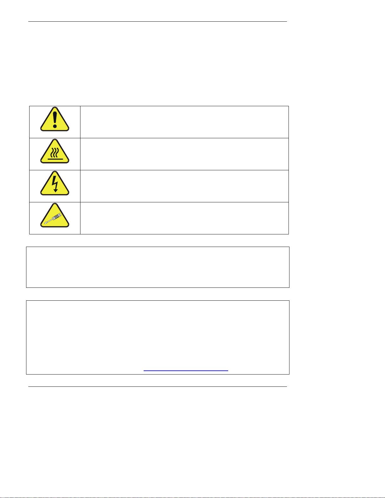
GENERAL SAFETY HAZARD: Refer to the instructions for details on the
specific hazard.
CAUTION: Hot Surface Warning
CAUTION: Electrical Shock Hazard
TECHNICIAN SYMBOL: All operations marked with this symbol are to
be performed by qualified maintenance personnel only.
CAUTION
The analyzer should only be used for the purpose and in the manner described in this
manual. If you use the analyzer in a manner other than that for which it was intended,
unpredictable behavior could ensue with possible hazardous consequences.
NOTE
Technical Assistance regarding the use and maintenance of the Model 6200E UV
Fluorescence H2S Analyzer or any other Teledyne Analytical Instruments product can be
obtained by:
Contacting Teledyne Analytical Instruments’ Customer Service Department at 800-324-
Via the internet at http://www.teledyne-ai.com
2 M6200E Rev: A1
5190
or

Model 6200E Instruction Manual
TABLE OF CONTENTS
1. M6200E DOCUMENTATION ......................................................................................................... 13
1.1. Using This Manual ................................................................................................................. 13
2. SPECIFICATIONS, APPROVALS AND WARRANTY........................................................................ 17
2.1. Specifications........................................................................................................................ 17
2.2. EPA Equivalency Designation...................................................................................................18
2.3. CE Mark Compliance ..............................................................................................................19
2.3.1. Emissions Compliance...................................................................................................... 19
2.3.2. Safety Compliance ..........................................................................................................19
2.4. Warranty..............................................................................................................................19
3. GETTING STARTED ..................................................................................................................... 21
3.1. Unpacking and Initial Setup .................................................................................................... 21
3.1.1. Electrical Connections:..................................................................................................... 23
3.1.1.1. Connecting the Analog Outputs...................................................................................24
3.1.1.2. Connecting the Status Outputs ................................................................................... 24
3.1.1.3. Connecting the Control Inputs .................................................................................... 26
3.1.1.4. Connecting the Serial Ports ........................................................................................ 27
3.1.1.5. Connecting to a LAN or the Internet ............................................................................ 27
3.1.1.6. Connecting to a LAN or the Internet ............................................................................ 27
3.1.2. Pneumatic Connections:................................................................................................... 27
3.1.2.1. Connections with Internal Valve Options Installed.......................................................... 30
3.2. Initial Operation .................................................................................................................... 32
3.2.1. Startup.......................................................................................................................... 32
3.2.2. Warm-Up.......................................................................................................................33
3.2.3. Warning Messages .......................................................................................................... 34
3.2.4. Functional Check.............................................................................................................36
3.3. Initial Calibration................................................................................................................... 38
3.3.1. Basic Calibration Procedure ..............................................................................................38
3.3.2. Interferences for H
4. FREQUENTLY ASKED QUESTIONS & GLOSSARY .......................................................................... 41
4.1. FAQ’s...................................................................................................................................41
4.2. Glossary............................................................................................................................... 42
5. OPTIONAL HARDWARE AND SOFTWARE .................................................................................... 45
5.1. Rack Mount Kits (Options 20a, 20b & 21)..................................................................................45
5.2. Current Loop Analog Outputs (Option 41) .................................................................................45
5.3. Particulate Filter Kit (Option 42A) ............................................................................................ 46
5.4. Calibration Valves Options ...................................................................................................... 46
5.4.1. Zero/Span Valves (Option 50)...........................................................................................46
5.4.2. Internal Zero/Span Gas Generator (Option 51)....................................................................48
5.4.3. IZS Permeation Tubes (Options 53, 55 & 57) ...................................................................... 51
5.4.4. Zero Air Scrubber Maintenance Kit (Option 43)....................................................................51
5.5. Multigas Measurement Option (option 82) .................................................................................52
5.6. Communication Options.......................................................................................................... 52
5.6.1. RS232 Modem Cable (Option 60)....................................................................................... 52
5.6.2. RS-232 Multidrop (Option 62) ........................................................................................... 52
5.6.3. Ethernet (Option 63) .......................................................................................................53
5.7. Additional Manuals................................................................................................................. 55
5.7.1. Printed Manuals (Option 70) ............................................................................................. 55
5.7.2. Manual on CD (Part number 047400200)............................................................................ 55
5.8. Extended Warranty (Options 92 & 93) ...................................................................................... 56
5.9. Special Software Features....................................................................................................... 56
5.9.1. Maintenance Mode Switch ................................................................................................56
5.9.2. Second Language Switch.................................................................................................. 56
5.9.3. Dilution Ratio Option .......................................................................................................56
6. OPERATING INSTRUCTIONS ...................................................................................................... 59
6.1. Overview of Operating modes .................................................................................................59
6.2. Sample Mode........................................................................................................................60
6.2.1. Test Functions ................................................................................................................ 60
6.2.2. Warning Messages .......................................................................................................... 63
S Measurements ................................................................................. 40
2
M6200E Rev: A1 3

Model 6200E Instruction Manual
6.3. Calibration Mode ...................................................................................................................64
6.3.1. SETUP – PASS: Calibration Password Security ..................................................................... 64
6.4. Setup Mode .......................................................................................................................... 66
6.4.1. SETUP Mode Password Security......................................................................................... 67
6.5. SETUP – CFG: Viewing the Analyzer’s Configuration Information ..................................................67
6.6. SETUP – CLK: Setting the Internal Time-of-Day Clock.................................................................68
6.7. SETUP – RNGE: Analog Output Reporting Range Configuration..................................................... 70
6.7.1. Available Analog Output Signals ........................................................................................ 70
6.7.2. Physical Range versus Analog Output Reporting Ranges........................................................ 71
6.7.3. Reporting Range Modes ................................................................................................... 71
6.7.4. Single Range mode (SNGL) .............................................................................................. 73
6.7.5. Independent Range Mode (IND) ........................................................................................ 74
6.7.6. Auto Range Mode (AUTO)................................................................................................. 75
6.7.7. Range Units ................................................................................................................... 76
6.7.8. Dilution Ratio ................................................................................................................. 77
6.8. SETUP – VARS: Using the Internal Variables.............................................................................. 78
6.8.1. Setting the Gas Measurement Mode................................................................................... 80
6.9. SETUP – DIAG: Using the Diagnostics Functions......................................................................... 81
6.9.1. Accessing the Diagnostic Features ..................................................................................... 82
6.9.2. Signal I/O ...................................................................................................................... 82
6.9.3. Analog Output Step Test .................................................................................................. 83
6.9.4. Analog I/O Configuration..................................................................................................84
6.9.4.1. Analog Output Signal Type and Range Span Selection.................................................... 86
6.9.4.2. Analog Output Calibration Mode.................................................................................. 86
6.9.4.3. Manual Analog Output Calibration and Voltage Adjustment ............................................. 89
6.9.4.4. Analog Output Offset Adjustment ................................................................................91
6.9.4.5. Current Loop Output Adjustment................................................................................. 91
6.9.4.6. AIN Calibration......................................................................................................... 93
6.9.5. Optic Test ...................................................................................................................... 95
6.9.6. Electrical Test.................................................................................................................96
6.9.7. Lamp Calibration............................................................................................................. 97
6.9.8. Pressure Calibration ........................................................................................................ 98
6.9.9. Flow Calibration .............................................................................................................. 99
6.9.10. Test Channel Output .................................................................................................... 100
6.10. SETUP – COMM: Setting Up the Analyser’s Communication Ports .............................................. 101
6.10.1. Analyzer ID ................................................................................................................ 101
6.10.2. COM Port Default Settings ............................................................................................ 103
6.10.3. RS-232 COM Port Cable Connections .............................................................................. 103
6.10.4. RS-485 Configuration of COM2 ...................................................................................... 104
6.10.5. DTE and DCE Communication........................................................................................ 106
6.10.6. Ethernet Card Configuration.......................................................................................... 107
6.10.6.1. Ethernet Card COM2 Communication Modes and Baud Rate......................................... 107
6.10.6.2. Configuring the Ethernet Interface Option using DHCP................................................ 107
6.10.6.3. Manually Configuring the Network IP Addresses......................................................... 110
6.10.6.4. Changing the Analyzer’s HOSTNAME ........................................................................ 112
6.10.7. Multidrop RS-232 Set Up .............................................................................................. 113
6.10.8. COM Port Communication Modes ................................................................................... 116
6.10.9. COM Port Baud Rate .................................................................................................... 118
6.10.10. COM Port Testing....................................................................................................... 119
6.11. Using the Data Acquisition System (iDAS) ............................................................................. 119
6.11.1. iDAS Structure............................................................................................................ 120
6.11.1.1. iDAS Channels...................................................................................................... 120
6.11.1.2. iDAS Parameters................................................................................................... 121
6.11.1.3. iDAS Triggering Events .......................................................................................... 122
6.11.2. Default iDAS Channels ................................................................................................. 122
6.11.2.1. Viewing iDAS Data and Settings .............................................................................. 125
6.11.2.2. Editing iDAS Data Channels .................................................................................... 126
6.11.2.3. Trigger Events ...................................................................................................... 128
6.11.2.4. Editing iDAS Parameters ........................................................................................ 128
6.11.2.5. Sample Period and Report Period............................................................................. 130
6.11.2.6. Number of Records ............................................................................................... 132
6.11.2.7. RS-232 Report Function ......................................................................................... 134
4 M6200E Rev: A1

Model 6200E Instruction Manual
6.11.2.8. Compact Report.................................................................................................... 134
6.11.2.9. Starting Date ....................................................................................................... 134
6.11.2.10. Disabling/Enabling Data Channels.......................................................................... 135
6.11.2.11. HOLDOFF Feature................................................................................................ 136
6.11.3. Remote iDAS Configuration........................................................................................... 137
6.12. Remote Operation of the Analyzer ........................................................................................ 139
6.12.1. Remote Operation Using the External Digital I/O.............................................................. 139
6.12.1.1. Status Outputs ..................................................................................................... 139
6.12.1.2. Control Inputs ...................................................................................................... 140
6.12.2. Remote Operation Using the External Serial I/O............................................................... 142
6.12.2.1. Terminal Operating Modes...................................................................................... 142
6.12.2.2. Help Commands in Terminal Mode........................................................................... 142
6.12.2.3. Command Syntax ................................................................................................. 143
6.12.2.4. Data Types .......................................................................................................... 143
6.12.2.5. Status Reporting................................................................................................... 144
6.12.2.6. Remote Access by Modem ...................................................................................... 145
6.12.2.7. COM Port Password Security................................................................................... 146
6.12.2.8. APICOM Remote Control Program............................................................................ 147
6.12.3. Additional Communications Documentation ..................................................................... 148
6.12.4. Using the M6200E with a Hessen Protocol Network........................................................... 149
6.12.4.1. General Overview of Hessen Protocol ....................................................................... 149
6.12.4.2. Hessen COMM Port Configuration ............................................................................ 149
6.12.4.3. Activating Hessen Protocol ..................................................................................... 150
6.12.4.4. Selecting a Hessen Protocol Type ............................................................................ 150
6.12.4.5. Setting The Hessen Protocol Response Mode............................................................. 151
6.12.4.6. Hessen Protocol Gas ID.......................................................................................... 153
6.12.4.7. Setting Hessen Protocol Status Flags ....................................................................... 154
6.12.4.8. Instrument ID Code .............................................................................................. 156
7. CALIBRATION PROCEDURES .....................................................................................................157
7.1. Calibration Preparations ....................................................................................................... 157
7.1.1. Required Equipment, Supplies, and Expendables ............................................................... 157
7.1.2. Zero Air ....................................................................................................................... 158
7.1.3. Gas Standards.............................................................................................................. 158
7.1.4. Permeation Tubes ......................................................................................................... 158
7.1.5. Calibration Gas Traceability ............................................................................................ 159
7.1.6. Data Recording Devices ................................................................................................. 159
7.2. Manual Calibration............................................................................................................... 159
7.3. Manual Calibration Checks .................................................................................................... 163
7.4. Manual Calibration with Zero/Span Valves............................................................................... 164
7.5. Manual Calibration with IZS Option ........................................................................................ 167
7.6. Manual Calibration Checks with IZS or Zero/Span Valves .......................................................... 168
7.7. Manual Calibration in INDEPENDENT or AUTO Reporting Range Modes......................................... 171
7.7.1. Calibration With Remote Contact Closures ........................................................................ 171
7.8. Manual Calibration in Multigas Measurement Mode ................................................................... 172
7.9. Automatic Calibration/Checks (AutoCal).................................................................................. 173
7.9.1. Autocal of instruments in INDEPENDENT or AUTO Reporting Range Modes............................. 176
7.9.2. Autocal of instruments in Multigas Measurement Mode ....................................................... 176
7.10. Calibration Quality ............................................................................................................. 177
8. EPA PROTOCOL CALIBRATION ..................................................................................................179
8.1. Calibration Requirements...................................................................................................... 179
8.1.1. Calibration of Equipment ................................................................................................ 179
8.1.2. Data Recording Device................................................................................................... 181
8.1.3. Recommended Standards for Establishing Traceability ........................................................ 181
8.1.4. EPA Calibration Using Permeation Tubes........................................................................... 181
8.1.5. Calibration Frequency .................................................................................................... 181
8.1.6. Record Keeping ............................................................................................................ 182
8.1.7. Summary of Quality Assurance Checks............................................................................. 182
8.2. Level 1 Calibrations versus Level 2 Checks.............................................................................. 183
8.3. ZERO and SPAN Checks........................................................................................................ 184
8.3.1. Zero/Span Check Procedures .......................................................................................... 184
8.4. Precisions Calibration Procedures and Checks .......................................................................... 184
8.4.1. Precision Calibration ...................................................................................................... 185
M6200E Rev: A1 5

Model 6200E Instruction Manual
8.4.2. Precision Check............................................................................................................. 185
8.5. Dynamic Multipoint Span Calibration ...................................................................................... 185
8.6. Special Calibration Requirements for Independent Range or Auto Range...................................... 186
8.7. References ......................................................................................................................... 187
9. INSTRUMENT MAINTENANCE ....................................................................................................189
9.1. Maintenance Schedule.......................................................................................................... 189
9.2. Predictive Diagnostics .......................................................................................................... 192
9.3. Maintenance Procedures....................................................................................................... 193
9.3.1. Changing the Sample Particulate Filter ............................................................................. 193
9.3.2. Changing the IZS Permeation Tube.................................................................................. 194
9.3.3. Maintaining the SO
9.3.3.1. Predicting When the SO
9.3.3.2. Checking the Function of the SO
9.3.3.3. Changing the SO
9.3.4. Changing the External Zero Air Scrubber .......................................................................... 196
9.3.5. Maintaining the H2S Æ SO
9.3.5.1. Predicting When the Converter Catalyst Should Be Replaced. ........................................ 197
9.3.5.2. Checking the Efficiency of the H2S Æ SO
9.3.5.3. Changing the H2S Æ SO
9.3.6. Cleaning the Sample chamber......................................................................................... 199
9.3.7. Cleaning or Changing Critical Flow Orifices........................................................................ 200
9.3.8. Checking for Light Leaks ................................................................................................ 201
10. THEORY OF OPERATION..........................................................................................................203
10.1. Measurement Principle ....................................................................................................... 203
10.1.1. H2S Conversion .......................................................................................................... 203
10.1.2. SO
10.2. The UV Light Path .............................................................................................................. 206
Ultraviolet Fluorescence ......................................................................................... 204
2
10.2.1. UV Source Lamp ......................................................................................................... 207
10.2.2. The Reference Detector................................................................................................ 208
10.2.3. The PMT..................................................................................................................... 208
10.2.4. Optical Filters ............................................................................................................. 208
10.2.4.1. UV Source Optical Filter ......................................................................................... 208
10.2.4.2. PMT Optical Filter.................................................................................................. 209
10.2.5. Optical Lenses ............................................................................................................ 210
10.2.6. Measurement Interferences .......................................................................................... 210
10.2.6.1. Direct Interference................................................................................................ 211
10.2.6.2. UV Absorption by Ozone ........................................................................................ 211
10.2.6.3. Dilution ............................................................................................................... 211
10.2.6.4. Third Body Quenching............................................................................................ 211
10.2.6.5. Light Pollution ...................................................................................................... 212
10.3. Pneumatic Operation.......................................................................................................... 212
10.3.1. sample gas Flow.......................................................................................................... 213
10.3.2. Multigas Measurement & H2S Æ SO
10.3.3. Flow Rate Control ........................................................................................................ 214
10.3.3.1. Critical Flow Orifice ............................................................................................... 214
10.3.4. Sample Particulate Filter............................................................................................... 215
10.3.5. Hydrocarbon Scrubber (Kicker) ..................................................................................... 215
10.3.6. SO
10.3.7. Pneumatic Sensors ...................................................................................................... 216
Scrubber.............................................................................................................. 216
2
10.3.7.1. Sample Pressure Sensor ........................................................................................ 216
10.3.7.2. Sample Flow Sensor .............................................................................................. 217
10.4. Electronic Operation........................................................................................................... 218
10.4.1. CPU........................................................................................................................... 219
10.4.1.1. Disk On Chip ........................................................................................................ 220
10.4.1.2. Flash Chip............................................................................................................ 220
10.4.2. Sensor Module & Sample chamber ................................................................................. 221
10.4.3. Sample Chamber Heating Circuit ................................................................................... 221
10.4.4. Photo Multiplier Tube (PMT) .......................................................................................... 222
10.4.5. PMT Cooling System. ................................................................................................... 223
10.4.5.1. Thermoelectric Cooler (TEC) ................................................................................... 223
10.4.5.2. TEC Control Board................................................................................................. 224
10.4.6. PMT Preamplifier ......................................................................................................... 224
Scrubber ......................................................................................... 194
2
Scrubber Should Be Replaced. ............................................... 194
2
Scrubber Material .......................................................................... 195
2
Converter .............................................................................. 197
2
Converter Catalyst Material ................................................... 198
2
Scrubber................................................................. 195
2
Converter..................................................... 197
2
Switching Valve. ....................................................... 213
2
6 M6200E Rev: A1

Model 6200E Instruction Manual
10.4.7. Pneumatic Sensor Board............................................................................................... 226
10.4.8. Relay Board................................................................................................................ 226
10.4.8.1. Heater Control...................................................................................................... 226
10.4.8.2. Valve Control ....................................................................................................... 226
10.4.9. Status LEDs & Watch Dog Circuitry ................................................................................ 227
10.4.10. Motherboard ............................................................................................................. 228
10.4.10.1. A to D Conversion ............................................................................................... 228
10.4.10.2. Sensor Inputs..................................................................................................... 228
10.4.10.3. Thermistor Interface............................................................................................ 229
10.4.11. Analog Outputs ......................................................................................................... 229
10.4.12. External Digital I/O.................................................................................................... 230
10.4.13. I
10.4.14. Power up Circuit ........................................................................................................ 230
10.5. Power Supply/ Circuit Breaker ............................................................................................. 230
10.6. Communications Interface .................................................................................................. 231
10.6.1. Front Panel Interface ................................................................................................... 232
10.7. Software Operation ............................................................................................................ 235
10.7.1. Adaptive Filter ............................................................................................................ 236
10.7.2. Calibration - Slope and Offset........................................................................................ 236
10.7.3. Temperature and Pressure Compensation (TPC) Feature ................................................... 237
10.7.4. Internal Data Acquisition System (iDAS)......................................................................... 238
11. TROUBLESHOOTING & REPAIR ...............................................................................................239
11.1. General Troubleshooting ..................................................................................................... 239
11.1.1. Fault Diagnosis with Warning Messages .......................................................................... 240
11.1.2. Fault Diagnosis with Test Functions................................................................................ 242
11.1.3. Using the Diagnostic Signal I/O Function......................................................................... 243
11.1.4. Status LEDs................................................................................................................ 244
11.2. Gas Flow Problems............................................................................................................. 246
11.2.1. Zero or Low Sample Flow ............................................................................................. 247
11.2.2. High Flow................................................................................................................... 247
11.3. Calibration Problems .......................................................................................................... 247
11.3.1. Negative Concentrations............................................................................................... 247
11.3.2. No Response .............................................................................................................. 248
11.3.3. Unstable Zero and Span ............................................................................................... 248
11.3.4. Inability to Span - No SPAN Key .................................................................................... 248
11.3.5. Inability to Zero - No ZERO Key..................................................................................... 249
11.3.6. Non-Linear Response ................................................................................................... 249
11.3.7. Discrepancy Between Analog Output and Display ............................................................. 250
11.4. Other Performance Problems ............................................................................................... 250
11.4.1. Excessive noise........................................................................................................... 250
11.4.2. Slow Response............................................................................................................ 250
11.4.3. The Analyzer Doesn’t Appear on the LAN or Internet ........................................................ 251
11.5. Subsystem Checkout.......................................................................................................... 251
11.5.1. Detailed Pressure Leak Check........................................................................................ 252
11.5.2. Performing a Sample Flow Check................................................................................... 252
11.5.3. AC Power Configuration................................................................................................ 253
11.5.4. DC Power Supply......................................................................................................... 253
11.5.5. I
11.5.6. Keyboard / Display Interface......................................................................................... 254
11.5.7. Relay Board................................................................................................................ 255
11.5.8. Motherboard............................................................................................................... 255
2
C Data Bus ............................................................................................................. 230
10.6.1.1. Analyzer Status LED’s............................................................................................ 233
10.6.1.2. Keyboard............................................................................................................. 233
10.6.1.3. Display................................................................................................................ 233
10.6.1.4. Keyboard/Display Interface Electronics..................................................................... 234
11.1.4.1. Motherboard Status Indicator (Watchdog) ................................................................ 244
11.1.4.2. CPU Status Indicator ............................................................................................. 245
11.1.4.3. Relay Board Status LEDs ........................................................................................ 245
2
C Bus ...................................................................................................................... 254
11.5.8.1. A/D functions ....................................................................................................... 255
11.5.8.2. Analog Output Voltages ......................................................................................... 256
11.5.8.3. Status Outputs ..................................................................................................... 256
11.5.8.4. Control Inputs ...................................................................................................... 257
M6200E Rev: A1 7

Model 6200E Instruction Manual
11.5.9. CPU........................................................................................................................... 257
11.5.10. RS-232 Communication .............................................................................................. 257
11.5.10.1. General RS-232 Troubleshooting ........................................................................... 257
11.5.10.2. Modem or Terminal Operation ............................................................................... 258
11.5.11. PMT Sensor .............................................................................................................. 258
11.5.12. PMT Preamplifier Board .............................................................................................. 259
11.5.13. PMT Temperature Control PCA ..................................................................................... 259
11.5.14. High Voltage Power Supply ......................................................................................... 260
11.5.15. Pneumatic Sensor Assembly........................................................................................ 260
11.5.15.1. Sample Pressure ................................................................................................. 260
11.5.16. IZS Option................................................................................................................ 260
11.5.17. Box Temperature....................................................................................................... 261
11.5.18. PMT Temperature ...................................................................................................... 261
11.6. Repair Procedures.............................................................................................................. 261
11.6.1. Disk-on-Chip Replacement............................................................................................ 261
11.6.2. Flash Chip Replacement or Upgrade ............................................................................... 262
11.6.3. Factory Cal (PMT Sensor, Hardware Calibration) .............................................................. 262
11.7. Technical Assistance .......................................................................................................... 264
12. A PRIMER ON ELECTRO-STATIC DISCHARGE...........................................................................265
12.1. How Static Charges are Created........................................................................................... 265
12.2. How Electro-Static Charges Cause Damage ........................................................................... 266
12.3. Common Myths About ESD Damage ..................................................................................... 267
12.4. Basic Principles of Static Control .......................................................................................... 268
12.4.1. General Rules ............................................................................................................. 268
12.4.2. Basic anti-ESD Procedures for Analyzer Repair and Maintenance ........................................ 270
12.4.2.1. Working at the Instrument Rack.............................................................................. 270
12.4.2.2. Working at a Anti-ESD Work Bench.......................................................................... 270
12.4.2.3. Transferring Components from Rack To Bench and Back............................................. 271
12.4.2.4. Opening Shipments from and Packing Components for Return to Teledyne Analytical
Instruments Customer Service. ............................................................................................
272
LIST OF APPENDICES
APPENDIX A - VERSION SPECIFIC SOFTWARE DOCUMENTATION
APPENDIX A-1: M6200E Software Menu Trees, Revision A.1
APPENDIX A-2: Setup Variables For Serial I/O, Revision A.1
APPENDIX A-3: Warnings and Test Functions, Revision A.1
APPENDIX A-4: M6200E Signal I/O Definitions, Revision A.1
APPENDIX A-5: M6200E iDAS Functions, Revision A.1
APPENDIX A-6: Terminal Command Designators, Revision A.1
APPENDIX B - M6200E SPARE PARTS LIST
APPENDIX C - REPAIR QUESTIONNAIRE - M6200E
APPENDIX D - ELECTRONIC SCHEMATICS
8 M6200E Rev: A1

Model 6200E Instruction Manual
LIST OF FIGURES
Figure 3-1: Location of Shipping Screws .......................................................................... 22
Figure 3-2: Rear Panel Layout........................................................................................ 23
Figure 3-3: Analog Output Connector .............................................................................. 24
Figure 3-4: Status Output Connector............................................................................... 25
Figure 3-5: Control Input Connector................................................................................ 26
Figure 3-6: Pneumatic Connections–Basic Configuration–Using Gas Dilution Calibrator ........... 28
Figure 3-7: Pneumatic Connections–Basic Configuration–Using Bottled Span Gas .................. 28
Figure 3-8: Basic Pneumatic Connections for Units with Valve Options ................................. 30
Figure 3-9: M6200E Layout (with IZS) ............................................................................ 31
Figure 3-10: Front Panel Layout ....................................................................................... 34
Figure 3-11: Pneumatic Diagram of the M6200E Standard Configuration. ............................... 37
Figure 5-1: Current Loop Option Installed on the Motherboard............................................ 46
Figure 5-2: Pneumatic Diagram of the M6200E With Z/S Option Installed. ............................ 47
Figure 5-3: Pneumatic Diagram of the M6200E with IZS Options Installed. ........................... 49
Figure 5-4: M6200E Multidrop Card................................................................................. 53
Figure 5-5: M6200E Ethernet Card.................................................................................. 54
Figure 5-6: M6200E Rear Panel with Ethernet Installed...................................................... 54
Figure 6-1: Front Panel Display ...................................................................................... 59
Figure 6-2 Viewing M6200E TEST Functions .................................................................... 62
Figure 6-3 Viewing and Clearing M6200E WARNING Messages ........................................... 64
Figure 6-4: Analog Output Connector Key........................................................................ 70
Figure 6-5: Setup for Calibrating Analog Outputs .............................................................. 90
Figure 6-6: Setup for Calibrating Current Outputs ............................................................. 92
Figure 6-7: Back Panel connector Pin-Outs for COM1 & COM2 in RS-232 mode.................... 103
Figure 6-8: CPU connector Pin-Outs for COM1 & COM2 in RS-232 mode............................. 104
Figure 6-9: CPU card Locations of RS-232/486 Switches, Connectors and Jumpers .............. 105
Figure 6-10: Back Panel connector Pin-Outs for COM2 in RS-485 mode................................ 106
Figure 6-11: CPU connector Pin-Outs for COM2 in RS-485 mode. ........................................ 106
Figure 6-12: Location of JP2 on RS232-Multidrop PCA (option 62) ...................................... 113
Figure 6-13: RS232-Multidrop PCA Host/Analyzer Interconnect Diagram .............................. 115
Figure 6-14: Default iDAS Channels Setup....................................................................... 124
Figure 6-15: APICOM user interface for configuring the iDAS. ............................................. 137
Figure 6-16: iDAS Configuration Through a Terminal Emulation Program.............................. 138
Figure 6-17: Status Output Connector............................................................................. 139
Figure 6-18: Control Inputs with local 5 V power supply..................................................... 141
Figure 6-19: Control Inputs with external 5 V power supply................................................ 141
Figure 6-20: APICOM Remote Control Program Interface.................................................... 148
Figure 7-1: Setup for Manual Calibration without Z/S valve or IZS Option .......................... 160
Figure 7-2: Setup for Manual Calibration with Z/S Valve Option Installed............................ 164
Figure 7-3: Setup for Manual Calibration Check with Z/S Valve or IZS Option ..................... 169
Figure 7-4: Typical Setup for Manual Calibration of M6200E in Multigas Measurement Mode .. 172
Figure 9-1: Sample Particulate Filter Assembly ............................................................... 193
Figure 9-2: Zero Air Scrubber Assembly ........................................................................ 196
Figure 9-3: H2S Æ SO
Figure 9-4: Critical Flow Orifice Assembly ...................................................................... 201
Figure 10-1: UV Absorption ........................................................................................... 205
Figure 10-2: UV Light Path ............................................................................................ 207
Figure 10-3: Source UV Lamp Construction...................................................................... 208
Figure 10-4: Excitation Lamp UV Spectrum Before/After Filtration....................................... 209
Figure 10-5: PMT Optical Filter Bandwidth........................................................................ 209
Figure 10-6: Effects of Focusing Source UV in Sample Chamber .......................................... 210
Figure 10-7: M6200E Gas Flow and Location of Critical Flow Orifice ..................................... 213
Converter Assembly ................................................................... 199
2
M6200E Rev: A1 9

Model 6200E Instruction Manual
Figure 10-8: Typical Flow Control Assembly with Critical Flow Orifice ................................... 215
Figure 10-9: M6200E Hydrocarbon Scrubber (Kicker) ........................................................ 216
Figure 10-10: M6200E Electronic Block Diagram ................................................................. 218
Figure 10-11: M6200E CPU Board..................................................................................... 220
Figure 10-12: M6200E Sample Chamber............................................................................ 221
Figure 10-13: PMT Assembly ........................................................................................... 222
Figure 10-14: Basic PMT Design ....................................................................................... 223
Figure 10-15: PMT Cooling System ................................................................................... 224
Figure 10-16: PMT Preamp Block Diagram ......................................................................... 225
Figure 10-17: Relay Board Status LED Locations................................................................. 227
Figure 10-18: Power Distribution Block Diagram................................................................. 231
Figure 10-19: Interface Block Diagram.............................................................................. 232
Figure 10-20: M6200E Front Panel Layout ......................................................................... 232
Figure 10-21: Keyboard and Display Interface Block Diagram ............................................... 234
Figure 10-22: Basic Software Operation ............................................................................ 236
Figure 11-1: Viewing and Clearing warning messages........................................................ 240
Figure 11-2: Example of Signal I/O Function .................................................................... 244
Figure 11-3: CPU Status Indicator .................................................................................. 245
Figure 11-4: Pre-Amplifier Board Layout.......................................................................... 263
Figure 12-1: Triboelectric Charging................................................................................. 265
Figure 12-2: Basic anti-ESD Work Station........................................................................ 268
Figure A-1: Basic Sample Display Menu ......................................................................... 275
Figure A-2: Sample Display Menu - Units with Z/S Valve or IZS Option installed.................. 276
Figure A-3: Primary Setup Menu (Except iDAS) .............................................................. 277
Figure A-4: Primary Setup Menu (iDAS)........................................................................ 278
Figure A-5: Secondary Setup Menu (COMM & VARS) ....................................................... 279
Figure A-6: Secondary Setup Menu (COMM Menu with Ethernet Card)................................ 280
Figure A-7: Secondary Setup Menu - HESSEN Submenu................................................. 281
Figure A-8: Secondary Setup Menu (DIAG) .................................................................... 282
LIST OF TABLES
Table 2-1: Model 6200E Basic Unit Specifications .............................................................. 17
Table 3–1: Analog output Pin Outs................................................................................... 24
Table 3-2: Status Output Signals.................................................................................... 25
Table 3-3: Control Input Signals..................................................................................... 26
Table 3-4: Inlet / Outlet Connector Nomenclature............................................................. 27
Table 3-5: NIST-SRM's Available for Traceability of H2S & SO
Table 3-6: Front Panel Display During System Warm-Up.................................................... 34
Table 3-7: Possible Warning Messages at Start-Up............................................................ 35
Table 3-8: H2S – SO
Switching Valve Operating States ..................................................... 37
2
Table 5-1: Zero/Span Valve Operating States.................................................................. 48
Table 5-2: IZS Valve Operating States ........................................................................... 49
Table 5-3: H2S – SO
Switching Valve Operating States ..................................................... 52
2
Table 6-1: Analyzer Operating modes.............................................................................. 60
Table 6-2: Test Functions Defined................................................................................... 61
Table 6-3: List of Warning Messages ............................................................................... 63
Table 6-4: Primary Setup Mode Features and Functions ..................................................... 66
Table 6-5: Secondary Setup Mode Features and Functions ................................................. 66
Table 6-6: Variable Names (VARS) Revision A.1 ............................................................... 78
Table 6-7: M6200E Diagnostic (DIAG) Functions............................................................... 81
Table 6-8: DIAG - Analog I/O Functions........................................................................... 84
Table 6-9: Analog Output Voltage Ranges ........................................................................ 84
Table 6-10: Analog Output Current Loop Range .................................................................. 85
10 M6200E Rev: A1
Calibration Gases .................... 29
2

Model 6200E Instruction Manual M6200E Documentation
Table 6-11: Analog Output Pin Assignments ....................................................................... 85
Table 6-12: Voltage Tolerances for Analog Output Calibration ............................................... 89
Table 6-13: Current Loop Output Calibration with Resistor ................................................... 93
Table 6-14: Test Parameters Available for Analog Output A4 .............................................. 100
Table 6-15: Ethernet Status Indicators............................................................................ 107
Table 6-16: LAN/Internet Configuration Properties............................................................ 108
Table 6-17: Internet Configuration Keypad Functions ........................................................ 113
Table 6-18: COMM Port Communication modes................................................................. 116
Table 6-19: Front Panel LED Status Indicators for iDAS ..................................................... 120
Table 6-20: iDAS Data Channel Properties ....................................................................... 121
Table 6-21: iDAS Data Parameter Functions..................................................................... 122
Table 6-22: Status Output Pin Assignments...................................................................... 140
Table 6-23: Control Input Pin Assignments....................................................................... 141
Table 6-24: Terminal Mode Software Commands .............................................................. 142
Table 6-25: Command Types ......................................................................................... 143
Table 6-26: Serial Interface Documents........................................................................... 148
Table 6-27: RS-232 Communication Parameters for Hessen Protocol ................................... 149
Table 6-28: M6200E Hessen Protocol Response Modes....................................................... 151
Table 6-29: Default Hessen Status Bit Assignments........................................................... 154
Table 7-1: NIST-SRM's Available for Traceability of H2S and SO
Calibration Gases ............... 159
2
Table 7-2: AutoCal Modes............................................................................................ 173
Table 7-3: AutoCal Attribute Setup Parameters............................................................... 173
Table 7-4: Example Auto-Cal Sequence ......................................................................... 174
Table 7-5: Calibration Data Quality Evaluation................................................................ 177
Table 8-1: Activity Matrix for Calibration Equipment & Supplies......................................... 180
Table 8-2: Activity Matrix for Calibration Procedure ......................................................... 180
Table 8-3: Activity Matrix ............................................................................................ 182
Table 8-4: Definition of Level 1 and Level 2 Zero and Span Checks.................................... 183
Table 9-1: M6200E Preventive Maintenance Schedule ...................................................... 190
Table 9-2: Predictive Uses for Test Functions.................................................................. 192
Table 10-1: M6200E Multigas Valve Cycle-Phases ............................................................. 214
Table 10-2: Relay Board Status LED’s ............................................................................. 227
Table 10-3: Front Panel Status LED’s .............................................................................. 233
Table 11-1: Warning Messages - Indicated Failures........................................................... 241
Table 11-2: Test Functions - Possible Causes for Out-Of-Range Values................................. 243
Table 11-3: Relay Board Status LEDs .............................................................................. 246
Table 11-4: DC Power Test Point and Wiring Color Code .................................................... 253
Table 11-5: DC Power Supply Acceptable Levels ............................................................... 254
Table 11-6: Relay Board Control Devices ......................................................................... 255
Table 11-7: Analog Output Test Function - Nominal Values................................................. 256
Table 11-8: Status Outputs Check Pin Out ....................................................................... 256
Table 12-1: Static Generation Voltages for Typical Activities............................................... 266
Table 12-2: Sensitivity of Electronic Devices to Damage by ESD ......................................... 266
Table A-1: M6200E Setup Variables, Revision A.1 ........................................................... 283
Table A-2: M6200E Warning Messages, Revision A.1 ....................................................... 290
Table A-3: M6200E Test Functions, Revision A.1 ............................................................. 291
Table A-4: M6200E Signal I/O Definitions, Revision A.1 ................................................... 292
Table A-5: M6200E DAS Trigger Events, Revision A.1 ...................................................... 296
Table A-6: M6200E iDAS Functions, Revision A.1 ............................................................ 297
Table A-7: Terminal Command Designators, Revision A.1................................................. 298
Table A-8: Terminal Key Assignments, Revision A.1 ........................................................ 299
Table B-1: M6200E Spare Parts List .............................................................................. 301
Table D-1: List of Included Electronic Schematics............................................................ 305
M6200E Rev: A1 11


Model 6200E Instruction Manual M6200E Documentation
1. M6200E DOCUMENTATION
Thank you for purchasing the Model 6200E UV Fluorescence H2S Analyzer!
The documentation for this instrument is available in several different formats:
• Printed format, part number M6200E
• Electronic format on a CD-ROM, part number M6200E_CD
®
The electronic manual is in Adobe
Acrobat Reader
the internet at http://
The electronic version of the manual has many advantages:
• Keyword and phrase search feature
• Figures, tables and internet addresses are linked so that clicking on the item will display
the associated feature or open the website.
• A list of chapters and sections as well as thumbnails of each page are displayed to the left
of the text.
• Entries in the table of contents are linked to the corresponding locations in the manual.
®
software, which is necessary to view these files, can be downloaded for free from
www.adobe.com/.
Systems Inc. “Portable Document Format”. The Adobe®
• Ability to print sections (or all) of the manual
Additional documentation for the Model 6200E UV Fluorescence H
Teledyne Analytical Instruments’ website at http://www.teledyne-api.com/manuals/
• APICOM software manual, part number 03945
• Multi-drop manual, part number 01842
• DAS Manual, part number 02837.
S Analyzer is available from
2
1.1. Using This Manual
This manual has the following data structures:
1.0 Table of Contents:
Outlines the contents of the manual in the order the information is presented. This is a good
overview of the topics covered in the manual. There is also a list of tables, a list of figures and a
list of appendices. In the electronic version of the manual, clicking on a any of these table entries
automatically views that section.
M6200E Rev: A1 13

M6200E Documentation Model 6200E Instruction Manual
2.0 Specifications and Warranty
This section contains a list of the analyzer’s performance specifications, a description of the
conditions and configuration under which EPA equivalency was approved and Teledyne Analytical
Instruments Incorporated warranty statement.
3.0 Getting Started:
A concise set of instructions for setting up, installing and running your analyzer for the first time.
4.0 FAQ:
Answers to the most frequently asked questions about operating the analyzer.
5.0 Optional Hardware & Software
A description of optional equipment to add functionality to your analyzer.
6.0 Operation Instructions
This section includes step by step instructions for operating the analyzer and using its various
features and functions.
7.0 Calibration Procedures
General information and step by step instructions for calibrating your analyzer.
8.0 Instrument Maintenance
Description of certain preventative maintenance procedures that should be regularly performed on
you instrument to keep it in good operating condition. This section also includes information on
using the iDAS to record diagnostic functions useful in predicting possible component failures
before they happen.
9.0 Theory of Operation
An in-depth look at the various principals by which your analyzer operates as well as a description
of how the various electronic, mechanical and pneumatic components of the instrument work and
interact with each other. A close reading of this section is invaluable for understanding the
instrument’s operation.
10.0 Troubleshooting Section:
This section includes pointers and instructions for diagnosing problems with the instrument, such
as excessive noise or drift, as well as instructions on performing repairs of the instrument’s major
subsystems.
11.0 Electro-static Discharge Primer
This section describes how static electricity occurs; why it is a significant concern and; how to
avoid it and avoid allowing ESD to affect the reliable and accurate operation of your analyzer.
14 M6200E Rev: A1

Model 6200E Instruction Manual M6200E Documentation
Appendices:
For easier access and better updating, some information has been separated out of the manual
and placed in a series of appendices at the end of this manual. These include: software menu
trees, warning messages, definitions of iDAS & serial I/O variables, spare parts list, repair
questionnaire, interconnect listing and drawings, and electronic schematics.
NOTE
Throughout this manual, words printed in capital, bold letters, such as SETUP or ENTR
represent messages as they appear on the analyzer’s front panel display.
NOTE
The flowcharts in this manual contain typical representations of the analyzer’s display
during the various operations being described. These representations are not intended
to be exact and may differ slightly from the actual display of your instrument.
User Notes:
M6200E Rev: A1 15


Model 6200E Instruction Manual Specifications, Approvals and Warranty
2. SPECIFICATIONS, APPROVALS AND
WARRANTY
2.1. Specifications
Table 2-1: Model 6200E Basic Unit Specifications
Min/Max Range
(Physical Analog Output)
Measurement Units ppb, ppm, µg/m3, mg/m3 (user selectable)
Zero Noise1 0.2 ppb RMS
Span Noise1 0.2 ppb RMS
Lower Detectable Limit2 0.4 ppb RMS
Zero Drift (24 hours) <0.5 ppb
Zero Drift (7 days) 1 ppb
Span Drift (7 Days) <0.5% FS
Linearity 1% of full scale
Precision 0.5% of reading1
Temperature Coefficient < 0.1% per oC
Voltage Coefficient < 0.05% per V
Rise/Fall Time1 95% in <100 sec
Sample Flow Rate 650cc/min. ±10%
Temperature Range 5-40oC
Humidity Range 0 - 95% RH, non-condensing
Dimensions H x W x D 7" x 17" x 23.5" (178 mm x 432 mm x 597 mm)
Weight, Analyzer
(Basic Configuration)
AC Power Rating 100 V, 50/60 Hz (1.7 A / 2.3 A surge);
Environmental Installation category (over-voltage category) II; Pollution degree 2
Analog Outputs Three (3) Outputs
Analog Output Ranges 100 mV, 1 V, 5 V, 10 V, 2-20 or 4-20 mA isolated current loop.
Analog Output Resolution 1 part in 4096 of selected full-scale voltage
Status Outputs 8 Status outputs from opto-isolators
Control Inputs 6 Control Inputs, 3 defined, 3 spare
Serial I/O One (1) RS-232; One (1) RS-485 (2 connecters in parallel)
Certifications
In 1 ppb increments from 50 ppb to 20 000 ppb, independent ranges or auto
ranging
45 lbs (20.5 kg) w/internal pump
115 V, 60 Hz (1.5 A / 2.0 A surge);
220 – 240 V, 50/60 Hz (.0.75 A \ 1.0 A surge)
All Ranges with 5% Under/Over Range
Baud Rate : 300 – 115200: Optional Ethernet Interface
EN61326 (1997 w/A1: 98) Class A, FCC Part 15 Subpart B Section
15.107 Class A, ICES-003 Class A (ANSI C63.4 1992) & AS/NZS
3548 (w/A1 & A2; 97) Class A
IEC 61010-1:90 + A1:92 + A2:95,
For indoor use at altitudes ≤ 2000m only
1
As defined by the USEPA.
2
Defined as twice the zero noise level by the USEPA.
M6200E Rev: A1 17

Specifications, Approvals and Warranty Model 6200E Instruction Manual
2.2. EPA Equivalency Designation
The Model 6200E Analyzer is designated as Reference Method Number EQOA-XXXX-XXX as per 40
CFR Part 53 when operated under the following conditions:
• Range: Any range from 50 parts per billion (ppb) to 10 parts per million (ppm).
o
• Ambient temperature range of 5
• Line voltage range of 105-125 VAC or 220-240 VAC, at 50 or 60 Hz.
• Sample filter: Equipped with PTFE filter element in the internal filter assembly.
• Sample flow of 650 +/- 65 cc/min.
• Vacuum pump (internal or external) capable of 14"Hg absolute pressure @ 1 slpm or
better.
• Software settings:
Dynamic span OFF
Dynamic zero OFF
Dilution factor OFF
AutoCal ON or OFF
IND range ON or OFF
Auto-range ON or OFF
Temp/Pressure compensation ON
Under the designation, the analyzer may be operated with or without the following optional
equipment:
• Rack mount with or without chassis slides.
C to 40 oC.
• Zero/span valve options.
• Internal zero/span (IZS) option with:
S permeation tube - 0.4ppm at 0.7 liter per minute; certified/uncertified.
• H
2
• H
S permeation tube - 0.8 ppm at 0.7 liter per minute; certified/uncertified. Under the
2
designation, the IZS option cannot be used as the source of calibration.
• 4-20mA isolated analog outputs.
• Status outputs.
• Control inputs.
• RS-232 output.
• Ethernet output.
• Zero air scrubber.
• 4-20mA, isolated output.
18 M6200E Rev: A1

Model 6200E Instruction Manual Specifications, Approvals and Warranty
2.3. CE Mark Compliance
2.3.1. Emissions Compliance
The Teledyne Analytical Instruments UV Fluorescence H2S Analyzer M6200E was tested and found
to be fully compliant with:
EN61326 (1997 w/A1: 98) Class A, FCC Part 15 Subpart B Section 15.107 Class A, ICES-003
Class A (ANSI C63.4 1992) & AS/NZS 3548 (w/A1 & A2; 97) Class A.
Tested on 07-21-03, 2003 at CKC Laboratories, Inc., Report Number CE03-021.
2.3.2. Safety Compliance
The Teledyne Analytical Instrument’s UV Fluorescence H2S Analyzer M6200E was tested and found
to be fully compliant with:
IEC 61010-1:90 + A1:92 + A2:95,
Tested on 04-04-03, 2003 at CKC Laboratories, Inc., Report Number WO 80146.
2.4. Warranty
Warranty Policy (02024)
Prior to shipment, Teledyne Analytical Instruments Incorporated equipment is thoroughly
inspected and tested. Should equipment failure occur, Teledyne Analytical Instruments
Incorporated assures its customers that prompt service and support will be available.
Coverage
After the warranty period and throughout the equipment lifetime, Teledyne Analytical Instruments
Incorporated stands ready to provide on-site or in-plant service at reasonable rates similar to
those of other manufacturers in the industry. All maintenance and the first level of field
troubleshooting is to be performed by the customer.
Non-TAI Manufactured Equipment
Equipment provided but not manufactured by Teledyne Analytical Instruments Incorporated is
warranted and will be repaired to the extent and according to the current terms and conditions of
the respective equipment manufacturers warranty.
General
Teledyne Analytical Instruments Incorporated warrants each product manufactured by Teledyne
Analytical Instruments Incorporated to be free from defects in material and workmanship under
normal use and service for a period of one year from the date of delivery. All replacement parts
and repairs are warranted for 90 days after the purchase.
If a product fails to conform to its specifications within the warranty period, Teledyne Analytical
Instruments Incorporated shall correct such defect by, in Teledyne Analytical Instruments’
discretion, repairing or replacing such defective product or refunding the purchase price of such
product.
M6200E Rev: A1 19

Specifications, Approvals and Warranty Model 6200E Instruction Manual
The warranties set forth in this section shall be of no force or effect with respect to any product:
(i) that has been altered or subjected to misuse, negligence or accident, or (ii) that has been used
in any manner other than in accordance with the instruction provided by Teledyne Analytical
Instruments Incorporated or (iii) not properly maintained.
THE WARRANTIES SET FORTH IN THIS SECTION AND THE REMEDIES THEREFORE ARE
EXCLUSIVE AND IN LIEU OF ANY IMPLIED WARRANTIES OF MERCHANTABILITY, FITNESS FOR
PARTICULAR PURPOSE OR OTHER WARRANTY OF QUALITY, WHETHER EXPRESSED OR IMPLIED.
THE REMEDIES SET FORTH IN THIS SECTION ARE THE EXCLUSIVE REMEDIES FOR BREACH OF
ANY WARRANTY CONTAINED HEREIN. TELEDYNE ANALYTICAL INSTRUMENTS INCORPORATED
SHALL NOT BE LIABLE FOR ANY INCIDENTAL OR CONSEQUENTIAL DAMAGES ARISING OUT OF
OR RELATED TO THIS AGREEMENT OF TELEDYNE ANALYTICAL INSTRUMENTS INCORPORATED'S
PERFORMANCE HEREUNDER, WHETHER FOR BREACH OF WARRANTY OR OTHERWISE.
Terms and Conditions
All units or components returned to Teledyne Analytical Instruments Incorporated should be
properly packed for handling and returned freight prepaid to the nearest designated Service
Center. After the repair, the equipment will be returned, freight prepaid.
User Notes:
20 M6200E Rev: A1
Model 6200E Instruction Manual Getting Started
3. GETTING STARTED
3.1. Unpacking and Initial Setup
CAUTION
To avoid personal injury, always use two persons to lift and carry the
1. Inspect the received packages for external shipping damage. If damaged, please advise the
shipper first, then Teledyne Analytical Instruments.
2. Included with your analyzer is a printed record (Form number 04551) of the final performance
characterization performed on your instrument at the factory. This record is an important
quality assurance and calibration record for this instrument. It should be placed in the quality
records file for this instrument.
3. Carefully remove the top cover of the analyzer and check for internal shipping damage.
• Remove the set screw located in the top, center of the rear panel
• Remove the screws fastening the top cover to the unit (four per side).
• Lift the cover straight up.
Model 6200E.
NOTE
Printed circuit assemblies (PCAs) are static sensitive. Electro-static discharges (ESD),
too small to be felt by the human nervous system, are large enough to destroy sensitive
Before touching PCAs, read Chapter 12 of this manual and follow the procedure
described there for avoiding damage to your instrument due to ESD.
Never disconnect electronic circuit boards, wiring harnesses or
4. Inspect the interior of the instrument to make sure all circuit boards and other components
are in good shape and properly seated.
5. Check the connectors of the various internal wiring harnesses and pneumatic hoses to make
sure they are firmly and properly seated.
M6200E Rev: A1 21
electronic subassemblies while the unit is under power.
circuits.
CAUTION
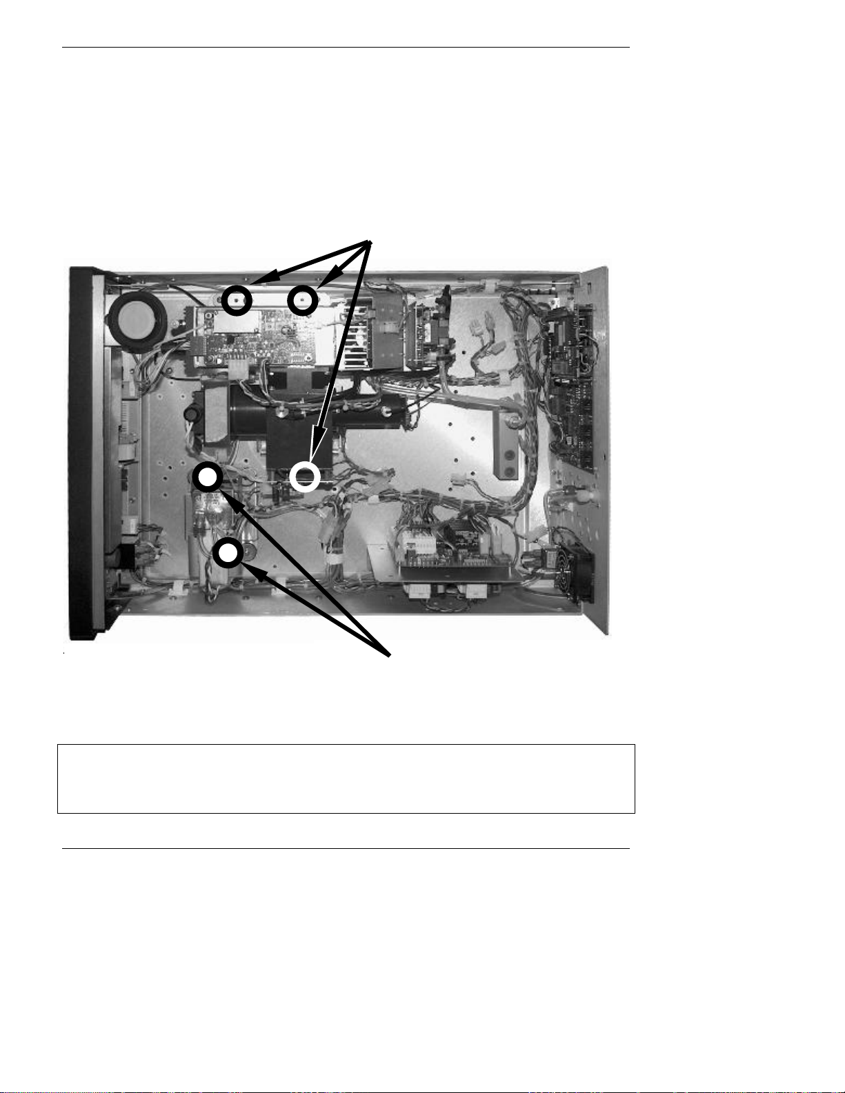
Getting Started Model 6200E Instruction Manual
6. Verify that all of the optional hardware ordered with the unit has been installed. These are
checked on the paperwork (Form 04551) accompanying the analyzer.
7. Once you have determined that no shipping damage exists and the unit includes all expected
hardware options, remove five, RED colored shipping screws from the bottom of the chassis,
shown in Figure 3-1. There are:
• Three locking down the sample chamber sensor housing assembly.,
• Two locking down the internal pump visible from bottom of instrument).
Sensor Housing Shipping Screws
Remove from inside of instrument.
Pump Shipping Screws
Remove from outside, bottom of instrument.
Figure 3-1: Location of Shipping Screws
NOTE
Save these shipping screws and re-install them whenever the unit is shipped.
22 M6200E Rev: A1
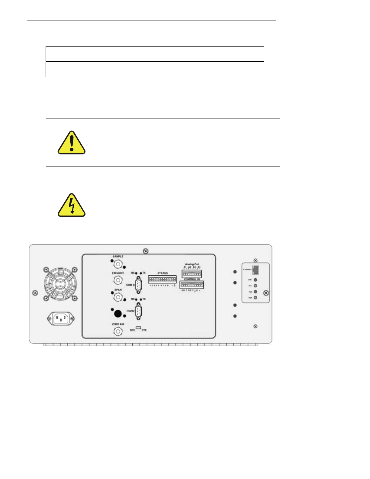
Model 6200E Instruction Manual Getting Started
8. VENTILATION CLEARANCE: Whether the analyzer is set up on a bench or installed into an
instrument rack, be sure to leave sufficient ventilation clearance.
AREA MINIMUM REQUIRED CLEARANCE
Back of the instrument 10 cm / 4 inches
Sides of the instrument 2.5 cm / 1 inch
Above and below the instrument. 2.5 cm / 1 inch
• Various rack mount kits are available for this analyzer. See Chapter 5 of this manual for
more information.
3.1.1. Electrical Connections:
CAUTION
Check the voltage and frequency label on the rear panel of the
instrument (See Figure 3-2) for compatibility with the local
power before plugging the M6200E into line power.
Power connection must have functioning ground connection.
Do not plug in the power cord if the voltage or
frequency is incorrect.
CAUTION
Do not defeat the ground wire on power plug.
Turn off analyzer power before disconnecting or
connecting electrical subassemblies.
Do not operate with cover off.
Figure 3-2: Rear Panel Layout
M6200E Rev: A1 23
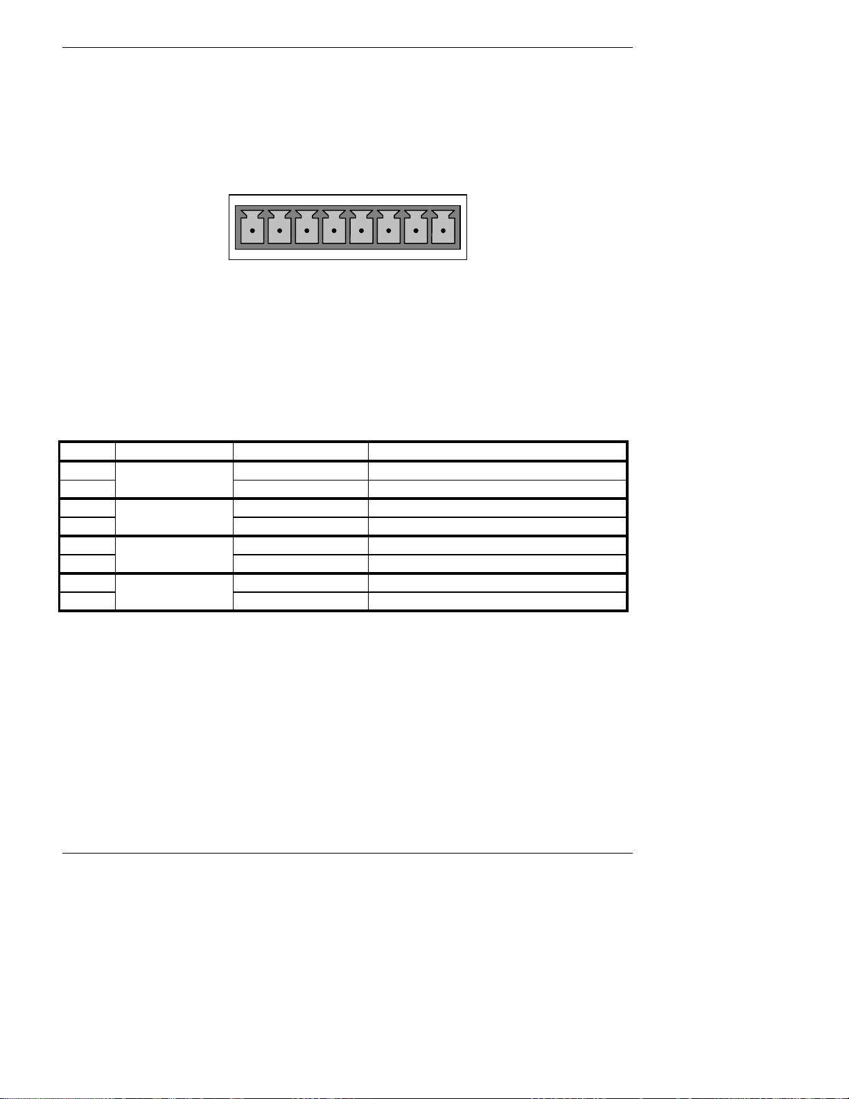
Getting Started Model 6200E Instruction Manual
3.1.1.1. Connecting the Analog Outputs
Attach a strip chart recorder and/or data-logger to the appropriate contacts of the analog output
connecter on the rear panel of the analyzer.
ANALOG OUT
A1 A2 A3 A4
+ - + - + - + -
Figure 3-3: Analog Output Connector
The A1 and A2 channels output a signal that is proportional to the H
S concentration of the
2
sample gas.
The output, labeled A4 is special. It can be set by the user (Section 6.9.10) to output any one of
the parameters accessible through the <TST TST> keys of the units sample display.
Pin-outs for the Analog Output connector at the rear panel of the instrument are:
Table 3–1: Analog output Pin Outs
PIN ANALOG OUTPUT VOLTAGE OUTPUT CURRENT LOOP OPTION
1 V Out I Out +
2
3 V Out I Out +
4
5 Not Available I Out +
6
7 V Out Not Available
8
A1
A2
A3
A4
Ground I Out -
Ground I Out -
Not Available I Out -
Ground Not Available
• The default analog output voltage setting of the M6200E UV Fluorescence H
S Analyzer is 0
2
– 5 VDC with a range of 0 – 500 ppb.
• TO change these settings, see Sections 6.9.4 and 6.7 respectively.
An optional Current Loop output is available for each (See Section 5.2).
3.1.1.2. Connecting the Status Outputs
The analyzer’s status outputs are accessed through a 12 pin connector on the analyzer’s rear
panel labeled STATUS. They are used to interface with a device that accepts closed-contact digital
inputs, such as programmable logic controllers (PLC’s).
24 M6200E Rev: A1
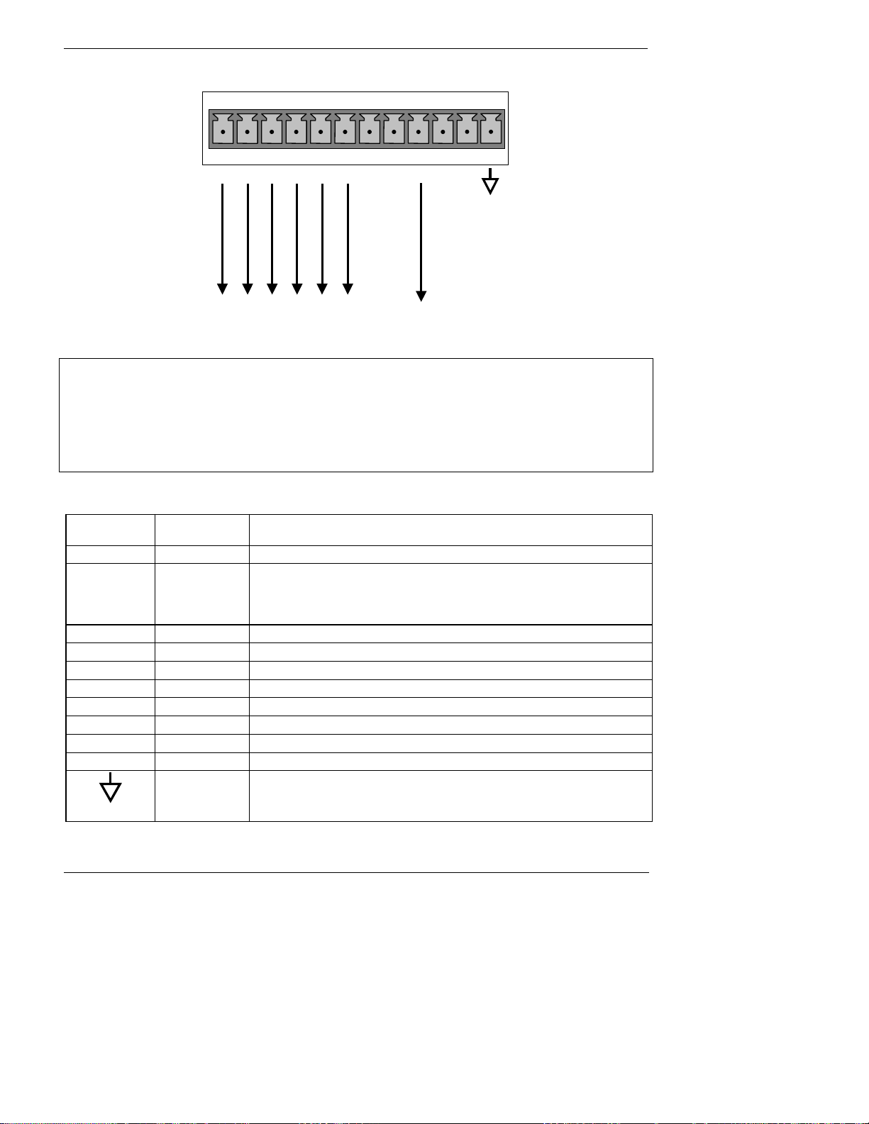
Model 6200E Instruction Manual Getting Started
K
1 2 3 4 5 6 7 8 D +
SYSTEM O
CONC VALID
HIGH RANGE
STATUS
ZERO CAL
SPAN CAL
DIAGNOSTIC MODE
Connect to Internal
Ground of Monitoring
Figure 3-4: Status Output Connector
NOTE
Most PLC’s have internal provisions for limiting the current the input will draw. When
connecting to a unit that does not have this feature, external resistors must be used to
limit the current through the individual transistor outputs to ≤50mA (120 Ω for 5V
supply).
Table 3-2: Status Output Signals
REAR PANEL
LABEL
1 SYSTEM OK ON if no faults are present.
2 CONC VALID
3 HIGH RANGE ON if unit is in high range of the AUTO Range Mode
4 ZERO CAL ON whenever the instrument’s ZERO point is being calibrated.
5 SPAN CAL ON whenever the instrument’s SPAN point is being calibrated.
6 DIAG MODE ON whenever the instrument is in DIAGNOSTIC mode
7 - 8 SPARE
D EMITTER BUS The emitters of the transistors on pins 1-8 are bussed together.
SPARE
+ DC POWER + 5 VDC, 300 mA source (combined rating with Control Output, if used).
STATUS
DEFINITION
Digital
Ground
CONDITION
OFF any time the HOLD OFF feature is active, such as during calibration
or when other faults exist possibly invalidating the current concentration
measurement (example: sample flow rate is outside of acceptable limits).
ON if concentration measurement is valid.
The ground level from the analyzer’s internal DC power supplies
M6200E Rev: A1 25
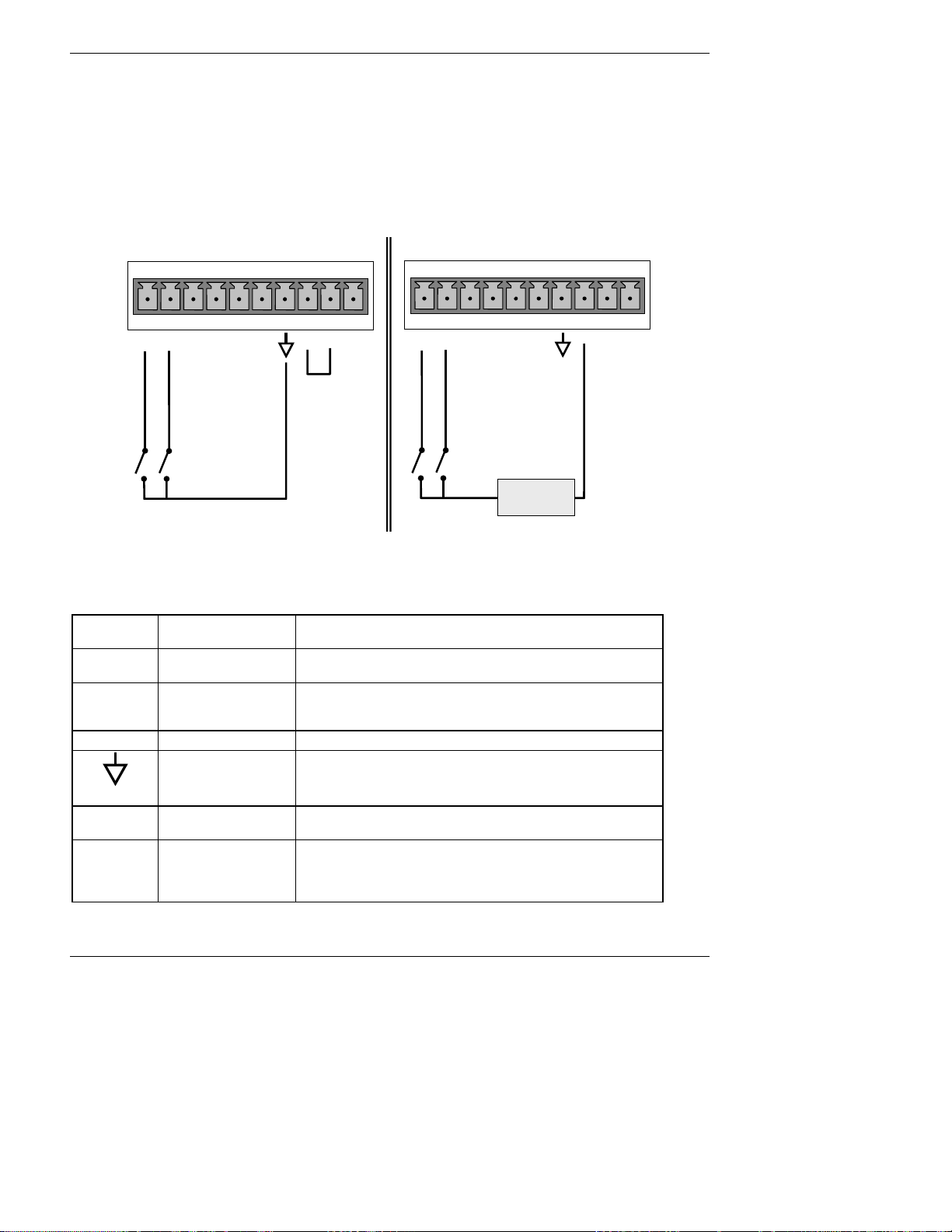
Getting Started Model 6200E Instruction Manual
3.1.1.3. Connecting the Control Inputs
If you wish to use the analyzer to remotely activate the zero and span calibration modes, several
digital control inputs are provided through a 10-pin connector labeled CONTROL IN on the
analyzer’s rear panel.
There are two methods for energizing the control inputs. The internal +5V available from the pin
labeled “+” is the most convenient method. However, if full isolation is required, an external 5
VDC power supply should be used.
CONTROL IN
CONTROL IN
A B C D E F U +
ZERO CAL
SPAN CAL
Local Power Connections
Figure 3-5: Control Input Connector
Table 3-3: Control Input Signals
INPUT #
A
B
C, D, E & F SPARE
STATUS
DEFINITION
REMOTE ZERO CAL
REMOTE
LO SPAN CAL
Digital Ground
A B C D E F U +
ZERO CAL
SPAN CAL
5 VDC Power
Supply
-
External Power Connections
+
ON CONDITION
The analyzer is placed in Zero Calibration mode. The mode
field of the display will read ZERO CAL R.
The analyzer is placed in low span calibration mode as part
of performing a low span (midpoint) calibration. The mode
field of the display will read LO CAL R.
The ground level from the analyzer’s internal DC power
supplies (same as chassis ground)
U External Power
input
+
5 VDC output
Input pin for +5 VDC required to activate pins A – F.
Internally generated 5V DC power. To activate inputs A – F,
place a jumper between this pin and the “U” pin. The
maximum amperage through this port is 300 mA (combined
with the analog output supply, if used).
26 M6200E Rev: A1

Model 6200E Instruction Manual Getting Started
3.1.1.4. Connecting the Serial Ports
If you wish to utilize either of the analyzer’s two serial interfaces, refer to Section 6.10 and 6.12
of this manual for instructions on configuration and usage.
3.1.1.5. Connecting to a LAN or the Internet
If your unit has a Teledyne Analytical Instruments Ethernet card (Option 63), plug one end of the
7’ CAT5 cable supplied with the option into the appropriate place on the back of the analyzer (see
Figure 5-6 in Section 5.6.3) and the other end into any nearby Ethernet access port.
3.1.1.6. Connecting to a LAN or the Internet
If your unit has a Teledyne Analytical Instruments RS-232 multidrop card (Option 62), see
section 10.6.7 fo instructions on setting it up.
3.1.2. Pneumatic Connections:
CAUTION
To prevent dust from getting into the analyzer, it was shipped with small plugs inserted
into each of the pneumatic fittings on the rear panel. Make sure that all dust plugs are
removed before attaching exhaust and supply gas lines.
Sample and calibration gases should only come into contact with PTFE (Teflon) or glass materials.
They should not come in contact with FEP or stainless steel materials.
Figures 3-6 and 3-7 show the most common configurations for gas supply and exhaust lines to the
Model 6200E Analyzer. Figure 3-8 shows the connections for units with valve options installed.
Please refer to Figure 3-2 for pneumatic connections at the rear panel and Table 3-4 for
nomenclature.
Table 3-4: Inlet / Outlet Connector Nomenclature
REAR PANEL LABEL FUNCTION
SAMPLE
EXHAUST Connects the exhaust of the analyzer with the external vacuum pump.
SPAN
ZERO AIR
Connects the sample gas to the analyzer. When operating the analyzer without
zero span option, this is also the inlet for any calibration gases.
On units with zero/span/shutoff valve options installed, connect a gas line to
the source of calibrated span gas here.
On Units with zero/span valve or IZS option installed, this port connects the
zero air gas or the zero air cartridge to the analyzer.
M6200E Rev: A1 27
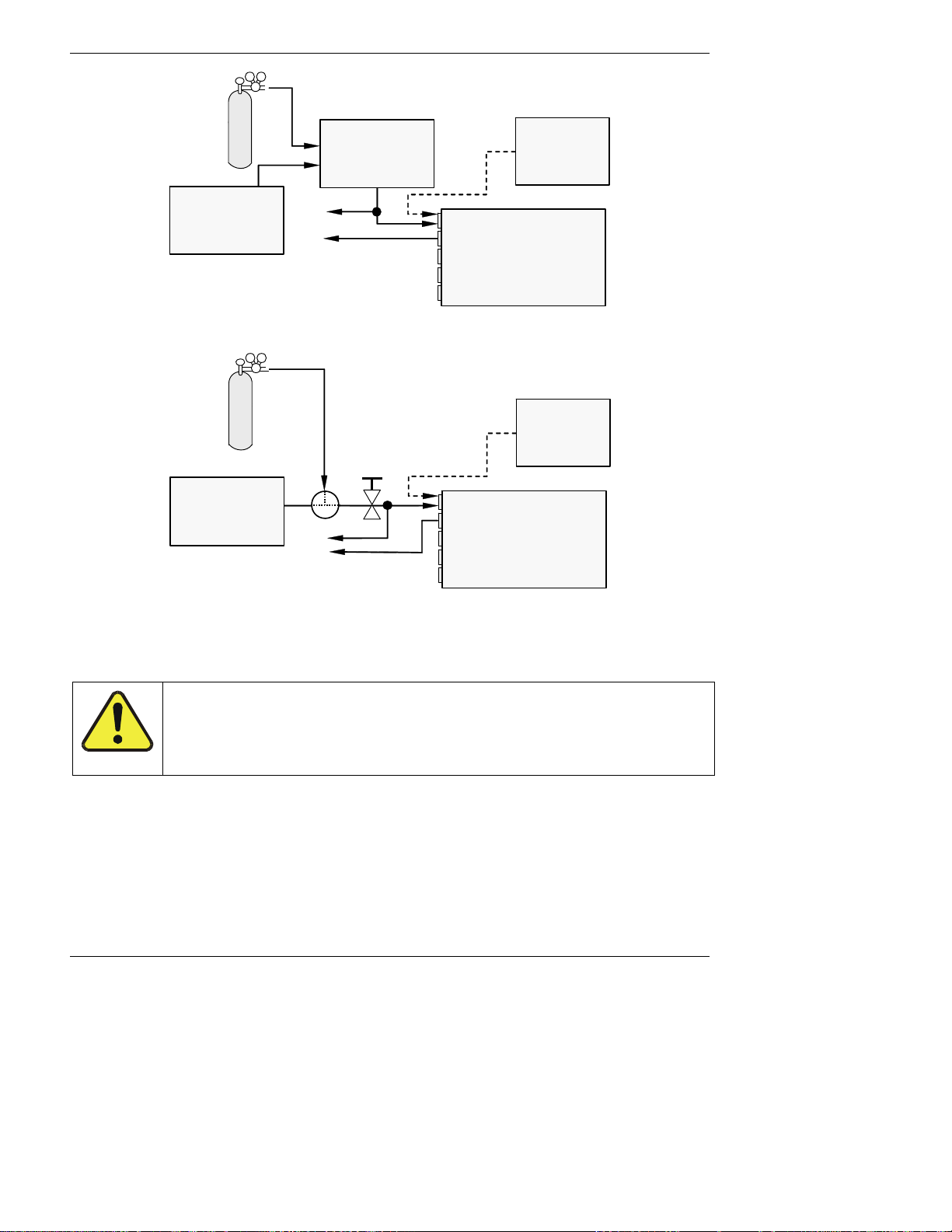
Getting Started Model 6200E Instruction Manual
Calibrated H2S GAS
(At high concentration)
MODEL 700 Gas
Dilution
Calibrator
(with Ozone Bench
Option)
Source of
SAMPLE Gas
Removed
during
Calibration
MODEL 701
Zero Air
Generator
VENT
Sample
Exhaust
Span
Zero Air
MODEL
6200E
Figure 3-6: Pneumatic Connections–Basic Configuration–Using Gas Dilution Calibrator
Calibrated SO2 or H2S GAS
(At span gas concentration)
Needle valve to control flow
MODEL 701
Zero Air
Generator
Valve
VENT
Sample
Exhaust
Span
Zero Air
Figure 3-7: Pneumatic Connections–Basic Configuration–Using Bottled Span Gas
1. Attach the 1/4" exhaust line to the exhaust port of the analyzer and to the inlet port of the
pump.
Source of
SAMPLE Gas
Removed
during
calibration
MODEL
6200E
CAUTION
The exhaust from the external pump needs to be vented outside the
immediate area or shelter surrounding the instrument and conform to all
safety requirements using a maximum of 10 meters of 1/4” PTFE tubing.
2. Attach the sample line to the sample inlet port. Ideally, the pressure of the sample gas should
be equal to ambient atmospheric pressure.
28 M6200E Rev: A1

Model 6200E Instruction Manual Getting Started
NOTE
Maximum pressure of any gas at the sample inlet should not exceed 1.5 in-Hg above
ambient pressure and ideally should equal ambient atmospheric pressure.
In applications where the sample gas is received from a pressurized manifold, a vent
must be provided to equalize the sample gas with ambient atmospheric pressure before
it enters the analyzer. The vented gas needs to be routed outside the immediate area or
shelter surrounding the instrument.
3. Attach zero air and span gas supply lines as appropriate (see Figures 3-6 & 3.7). For this type
of analyzer, zero air and span gas are defined as follows:
Zero air and span gas inlets should supply their respective gases in excess of the 700 cc
3
/min
demand of the analyzer. Supply and vent lines should be of sufficient length and diameter to
prevent back diffusion and pressure effects.
SPAN GAS
• A gas specifically mixed to match the chemical composition of the type of gas being
measured at near full scale of the desired measurement range. In the case of H
2
S,
measurements made with the Teledyne Analytical Instruments Model 6200E UV
Fluorescence H
S Analyzer it is recommended that you use a span gas with a H2S
2
concentration equal to 90% of the measurement range for your application.
EXAMPLE: If the application is to measure between 0 ppb and 500 ppb, an appropriate
span gas concentration would be 450 ppb H
Cylinders of calibrated H
S gas traceable to NIST-Standard Reference Material specifications
2
S in N2.
2
(also referred to as SRM’s or EPA protocol calibration gases) are commercially available. Table
3-5 lists specific NIST-SRM reference numbers for various concentrations of H
2
S.
Some applications, such as EPA monitoring, require a multipoint calibration procedure
where span gases of different concentrations are needed. We recommend using a bottle of
calibrated H
S gas of higher concentration in conjunction with a gas dilution calibrator such
2
as a Teledyne Analytical Instruments Model 700. This type of calibrator precisely mixes a
high concentration gas from zero air (both supplied externally) to accurately produce span
gas of the correct concentration. Linearity profiles can be automated with this model and
run unattended over night.
Table 3-5: NIST-SRM's Available for Traceability of H
NIST-SRM4 TYPE
2730
2731
1693a
1694a
1661a
Hydrogen sulfide in N
Hydrogen sulfide in N2
Sulfur dioxide in N
Sulfur dioxide in N
Sulfur dioxide in N2
2
2
2
S & SO2 Calibration Gases
2
NOMINAL
CONCENTRATION
5000 ppb
20 ppm
50 ppm
100 ppm
500 ppm
M6200E Rev: A1 29
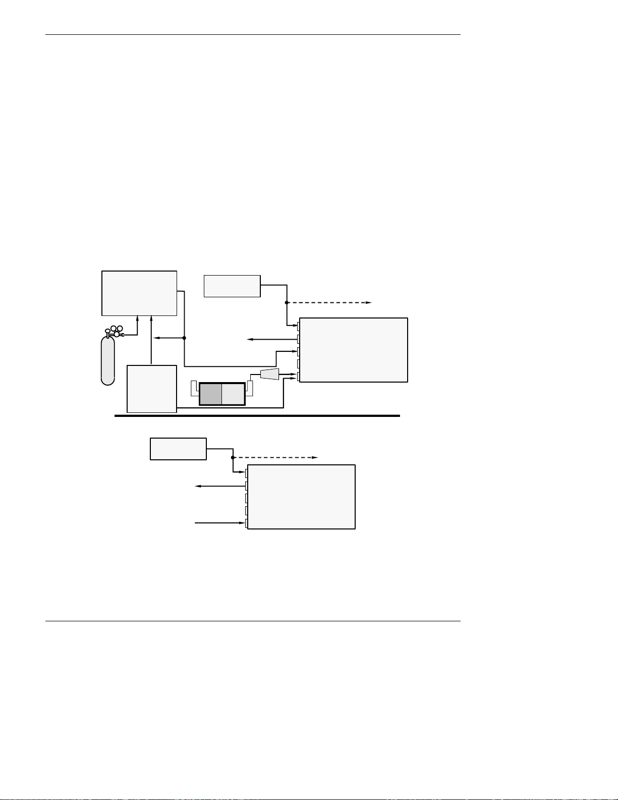
Getting Started Model 6200E Instruction Manual
Span
(
)
ZERO AIR
• A gas that is similar in chemical composition to the earth’s atmosphere but without the gas
being measured by the analyzer, in this case H
S. If your analyzer is equipped with an IZS
2
or external zero air scrubber option, it is capable of creating zero air.
For analyzers without these options, a zero air generator such as the Teledyne Analytical
Instruments Model 701 can be used.
4. Once the appropriate pneumatic connections have been made, check all pneumatic fittings for
leaks using a procedure similar to that defined in Section 11.5.1.
3.1.2.1. Connections with Internal Valve Options Installed
If your analyzer is equiped with either the zero/span valve option (Option 50) or the internal
zero/span option (Option 51), the pneumatic connections should be made as follows:
MODEL 700
Gas Dilution Calibrator
(with O3 generator option)
Source of
SAMPLE Gas
Zero/Span Valves – Option 50
VENT if input is pressurized
VENT
Calibrated SO2 or H2S
gas
At high concentration
MODEL 701
Zero Air
Generator
Sample
Exhaust
External Zero
Air Scrubber
Filter
Zero Air
MODEL
6200E
Internal Zero/Span Option (IZS) – Option 51
Source of
SAMPLE Gas
Ambient
Air
VENT if input is pressurized
Sample
Exhaust
Span
Zero Air
MODEL
6200E
Figure 3-8: Basic Pneumatic Connections for Units with Valve Options
30 M6200E Rev: A1
 Loading...