

Teledyne 4M, 12M, 8M, Falcon2 4M, DALSA Falcon2 4M User Manual
...
3-Feb-12
03-032-20107-01
www.teledynedalsa.com
Falcon2 4M, 8M, and 12M
Camera User’s Manual

2 Falcon2 4M, 8M, and 12M Camera User's Manual
North America
605 McMurray Rd
Waterloo, ON N2V 2E9
Canada
Tel: 519 886 6000
Fax: 519 886 8023
www.teledynedalsa.com
sales.americas@teledynedalsa.com
support@teledynedalsa.com
Europe
Breslauer Str. 34
D-82194 Gröbenzell (Munich)
Germany
Tel: +49 - 8142 – 46770
Fax: +49 - 8142 – 467746
www. teledynedalsa.com
sales.europe@teledynedalsa.com
support@teledynedalsa.com
Asia Pacific
Ikebukuro East 13F
3-4-3 Higashi-Ikebukuro
Toshima-ku, Tokyo 170-0013
Japan
Tel: 81 3 5960 6353
Fax: 81 3 5960 6354 (fax)
www.teledynedalsa.com
sales.asia@teledynedalsa.com
support@teledynedalsa.com
© 2012 Teled yne DALSA, Inc. All information provided in this manual is believed to be accurate and reliable. No responsibility is
assumed by Teledyne DALSA for its use. Teledyne DALSA reserves the right to make changes to this information without notice.
Reproduction of this manual in whole or in part, by any means, is prohibited without prior permission having been obtained from
Teled yne DALSA.
About Teledyne Technologies and Teledyne DALSA, Inc.
Teled yne Technologies is a leading provid er of sophisticated electronic subsystems, instrumentation and communication products,
en gin eered systems, aero sp a ce en gine s, and energy an d p ow er ge nera tio n systems. Teledyn e Techn ologies’ op erations ar e p rimar i ly
located in the United States, the United Kingdom and Mexico. For more information, visit Teled yne Tech nologies’ website a t
www.teledyne.com.
Teled yne DALSA, a Teledyne Technologies company, is an international leader in high performance digital imaging and
semiconductors with approximately 1,000 employees worldwide, headquartered in Waterloo, Ontario, Canad a. Established in 1980,
the company designs, develops, manufactures and markets digital imaging products and solutions, in addition to providing MEMS
products an d serv ices. For mo re information , visit Teled yne DA LSA’s w ebsite at w w w .teled ynedalsa.com.
Support
For further information not included in this manual, or for information on Teledyne DALSA’s extensive lin e of imag e sensing
products, please contact:
03-032-20107-01 Teledyne DALSA

Falcon2 4M, 8M, and 12M Camera User's Manual 3
Contents
1. System Precautions and Cleaning ___________________________________________________________________ 5
Precautions ..................................................................................................................................................... 5
Electrostatic Discharge and the CMOS Sensor ................................................................................................. 5
Protecting Against Dust, Oil, and Scratches .................................................................................................... 5
Cleaning the Sensor Window .......................................................................................................................... 6
2. The Falcon2 Camera ____________________________________________________________________________ 7
Camera Highlights ............................................................................................................................................................. 7
Camera Performance Specifications .................................................................................................................................. 9
Certifications ...................................................................................................................................................................... 10
Supported Industry Standards ........................................................................................................................................... 10
Responsivity ....................................................................................................................................................................... 11
Sensor Cosmetic Specifications........................................................................................................................................... 12
Sensor Block Diagram and Pixel Readout ........................................................................................................................ 13
Mechanicals ........................................................................................................................................................................ 14
3. Software and Hardware Setup______________________________________________________________________ 15
Minimum System Requirements ..................................................................................................................... 15
Setup Steps: Overview ....................................................................................................................................................... 15
1. Install and Configure Frame Grabber, Graphics Card, and GUI................................................................. 15
2. Connect Power and Camera Link Cables .................................................................................................... 15
3. Establish communicating with the camera .................................................................................................. 15
4. Check camera LED, settings and test pattern .............................................................................................. 15
5. Operate the Camera ................................................................................................................................... 15
Step 1. Install and configure the frame grabber, graphics card and GUI ......................................................................... 16
Install Frame Grabber .................................................................................................................................... 16
Install Graphics Card ....................................................................................................................................... 16
Install Sapera LT and CamExpert ................................................................................................................... 16
Step 2. Connect Power, Data, and Trigger Cables ............................................................................................................. 17
Power Connector ............................................................................................................................................. 17
LEDs ................................................................................................................................................................ 18
Data Connector: Camera Link ........................................................................................................................ 18
Camera Link cable quality and length ............................................................................................................ 23
Input Signals, Camera Link ............................................................................................................................ 23
Output Signals, Camera Link Clocking Signals............................................................................................... 23
Step 3. Establish Communication with the Camera ........................................................................................................... 24
Power on the camera ...................................................................................................................................... 24
Connect to the frame grabber ......................................................................................................................... 24
Connect to the camera .................................................................................................................................... 24
Check LED Status ............................................................................................................................................ 24
Software Interface ........................................................................................................................................... 24
Step 4. Check Camera Test Patterns and Set Trigger and Exposure Time ........................................................................ 26
Review a Test Image ....................................................................................................................................... 26
4. Camera Operation ______________________________________________________________________________ 27
Factory Settings ................................................................................................................................................................. 27
Teledyne DALSA 03-032-20107-01

4 Falcon2 4M, 8M, and 12M Camera User's Manual
Check Camera and Sensor Information ............................................................................................................................. 27
Saving and Restoring Camera Settings ............................................................................................................................. 28
Trigger Modes .................................................................................................................................................................... 30
Exposure Controls .............................................................................................................................................................. 30
Exposure Modes in Detail .................................................................................................................................................. 31
Internally Programmable Frame Rate and Internally Programmable Exposure Time (Default) .................. 31
External Frame Rate and External Exposure Time (Trigger Width) ............................................................... 32
External Frame Rate, Programmable Exposure Time .................................................................................... 33
Set Frame Rate .................................................................................................................................................................. 34
Set Exposure Time ............................................................................................................................................................. 35
Hot Pixels and Long Exposure Times .............................................................................................................. 35
Input / Output Control ....................................................................................................................................................... 35
Control Gain and Black Level ............................................................................................................................................ 37
Image Size ......................................................................................................................................................................... 37
Set Baud Rate .................................................................................................................................................................... 38
I / O Opto-couplers ............................................................................................................................................................ 39
Calibrating the Camera: Flat Field Correction .................................................................................................................. 40
File Access Control ............................................................................................................................................................. 44
Appendix A ____________________________________________________________________________________ 45
Defining Multiple Areas of Interest ................................................................................................................................... 45
Revision History _________________________________________________________________________________ 46
Index ________________________________________________________________________________________ 47
03-032-20107-01 Teledyne DALSA

Falcon2 4M, 8M, and 12M Camera User's Manual 5
1. System Precautions and
Cleaning
Precautions
Read these precautions and this manual carefully before using the camera.
Confirm that the cam era’s p ackagin g is und am aged before op en in g it. If th e p ackagin g is damaged p lease
contact the related logistics personnel.
Do not open the housing of the camera. The warranty is voided if the housing is opened.
Keep the camera housing temperature in a range of 10 °C to 50 °C during operation.
Do not operate the camera in the vicinity of strong electromagnetic fields. In addition, avoid electrostatic
charging, violent vibration, and excess moisture.
To clean the device, avoid electrostatic charging by using a dry, clean absorbent cotton cloth dampened
with a small quantity of pure alcohol. Do not use methylated alcohol. To clean the surface of the camera
housing, use a soft, dry cloth. To remove severe stains use a soft cloth dampened with a small quantity of
neutral detergent and then wipe dry. Do not use volatile solvents such as benzene and thinners, as they
can damage the surface finish. Further cleaning instructions are below.
This camera does not support hot plugging. Power down and disconnect power to the camera before you
add or replace system components.
Electrostatic Discharge and the CMOS Sensor
Image sensors and the camera bodies housing are susceptible to damage from electrostatic discharge
(ESD). Electrostatic charge introduced to the sensor window surface can induce charge buildup on the
underside of the window that cannot be readily dissipated by the dry nitrogen gas in the sensor package
cavity. The charge normally dissipates within 24 hours and the sensor returns to normal operation.
Protecting Against Dust, Oil, and Scratches
The sensor window is part of the optical path and should be handled like other optical components, with
extreme care. Dust can obscure pixels, producing dark patches on the sensor response. Du st is most
visible when the illumination is collimated. The dark patches shift position as the angle of illumination
changes. Dust is normally not visible when the sensor is positioned at the exit port of an integrating
sphere, where the illumination is diffuse. Dust can normally be removed by blowing the window surface
using an ionized air gun. Oil is usually introduced during handling. Touching the surface of the window
barehanded will leave oily residues. Using rubber fingercots and rubber gloves can prevent
contamination. However, the friction between rubber and the window may produce electrostatic charge
that may damage the sensor. To avoid ESD damage and to avoid introducing oily residues, avoid
touching the sensor. Scratches diffract incident illumination. When exposed to uniform illumination, a
sensor with a scratched window will normally have brighter pixels adjacent to darker pixels. The location
of these pixels will change with the angle of illumination.
Teledyne DALSA 03-032-20107-01

6 Falcon2 4M, 8M, and 12M Camera User's Manual
Cleaning the Sensor Window
Recommended Equipment
Glass cleaning station with microscope within clean room.
3M ionized air gun 980
(http:/ / solutions.3mcanada.ca/ wps/ portal/ 3M/ en_CA/ WW2/ Country/ )
Ionized air flood system, foot operated.
Swab (HUBY-340CA-003)
(http:/ / www.cleancross.net/ modules/ xfsection/ article.php?articleid=24)
Single drop bottle (FD-2-ESD)
E2 (Eclipse optic cleaning system (w ww.photosol.com)
Procedure
Use localized ionized air flow on to the glass during sensor cleaning.
Blow off mobile contamination using an ionized air gun.
Place the sensor under the microscope at a magnification of 5x to determine the
location of any remaining contamination.
Clean the contamination on the sensor using one drop of E2 on a swab.
Wipe the swab from left to right (or right to left but only in one direction). Do
this in an overlapping pattern, turning the swab after the first wipe and with
each subsequent wipe. Avoid swiping back and forth with the same swab in
order to ensure that particles are removed and not simply transferred to a new
location on the sensor window. This procedure requires you to use multiple
swabs.
Discard the swab after both sides of the swab have been used once.
Repeat until there is no visible contamination present.
03-032-20107-01 Teledyne DALSA

Falcon2 4M, 8M, and 12M Camera User's Manual 7
2. The Falcon2 Camera
Camera Highlights
The new Falcon2 4M, 8M, and 12M are Teledyne DALSA’s new gen eration of area scan cam eras . The
cameras incorporate large resolutions and faster frame rates enabling high speed image capture with
superb spatial resolution. Important features such as global shutter and improved image quality make
these Falcon2 cameras the camera of choice in applications where throughput, resolution, and dynamic
range matter. Global shuttering removes unwanted smear and time displacement artefacts related to
rolling shutter CMOS devices. Inside these Falcon2 cameras is our latest 4, 8 and 12 megapixel CMOS
sensor which has reduced dark noise levels and improved dark offset, FPN (fixed pattern noise) and
PRNU (Pixel Response Non-Uniformity) levels. In addition, region of interest features will offer
opportunities for higher frame rates and new applications.
The cameras are compliant with Cam era Link™ specifications, delivering 8 or 10 bits of data on 8 or 10
taps (frame rates are specified at 8 bits). Further, the M42x1 thread opening allows the use of your lens of
choice.
Key Features
12, 8 and 4 mega pixels
Selectable 4:3 or 1:1 aspect ratios
Global Shutter
Exposure control
Faster frame rates through windowing
Good NIR response
Built-in FPN and PRNU correction
Programmability
Adjustable digital gain and offset
8 or 10 bit selectable output
Adjustable integration time and frame rate
Test patterns and camera diagnostics
Applications
Automated Optical Inspection (AOI)
3D imaging—Laser profiling
Semiconductor wafer inspection
Solar panel inspection
Electronics manufacturing
Surface and bump inspection
3D solder paste inspection
General machine vision
Teledyne DALSA 03-032-20107-01

8 Falcon2 4M, 8M, and 12M Camera User's Manual
Model Number
Description
FA-80-12M1H-00-R
12M pixel monochrome Camera Link.
FA-81-12M1H-00-R
12M pixel color Camera Link.
FA-80-8M100-00-R
8M pixel monochrome Camera Link.
FA-81-8M100-00-R
8M pixel color Camera Link.
FA-80-4M180-00-R
4M pixel monochrome Camera Link.
FA-81-4M180-00-R
4M pixel color Camera Link.
Software
Product Number / Version Number
Camera firmware
Embedded within camera
GenICam™ support (XML camera description file)
Embedded within camera
Sapera LT, including CamExpert GUI application and GenICam
for Camera Link imaging driver
Version 7.2 or later
Models
The camera is available in the following configurations:
Table 1: Camera Models Overview
Table 2: Software
03-032-20107-01 Teledyne DALSA

Falcon2 4M, 8M, and 12M Camera User's Manual 9
Specifications
Performance
Resolution
4 : 3 aspect ratio: 12M—4096 (H) x 3072 (V)
8M—3328 (H) x 2502 (V)
4M—2432 (H) x 1728 (V)
1 : 1 aspect ratio: 8M—2816 (H) x 2816 (V)
4M—2048 (H) x 2048 (V)
Pixel Rate
8 x 76 MHz or 10 x 76 MHz (8 bits only)
Max. Frame Rate
12M—58 fps / 8M—90 fps / 4M—168 fps, 10 taps*
Pixel Size
6 µm x 6 µm
Exposure Time
20 µs minimum
Bit Depth
8 bits or 10 bits
Dynamic Range
57.3 dB, typical (12M, 10 bpp**)
Output Format, Taps
8 or 10 tap interleaved
Operating Temp
0 °C to 50 °C, front plate temperature
Connectors and
Mechanicals
Data Interface
2 x Full or Extended Camera Link—SDR26
Power Connector
Hirose 12-pin circular
Power Supply
+ 12 V to + 24 V DC
Power Dissipation
9.5 W, typical
Mini-USB connector
For diagnostics only
Lens Mount
M42 x 1 (F mount optional)
Size
60 mm (H) x 60 mm (W) x 80.5 mm (D)
Mass
< 300 g
Compliance
Regulatory Compliance
CE and RoHS
Mono Operating Ranges
Units
Notes
Random Noise
DN rms
1.4*
Typical, FFC enabled
Broadband Responsivity
DN/ (nJ/ cm2)
See graph
DC Offset
DN 0 FFC enabled
Antiblooming
>1000 x Saturation
FPN
DN rms
1.1*
Typical, FFC enabled
PRNU
DN rms
2.5*
Typical, FFC enabled
Integral non-linearity
DN
< 2%
Camera Performance Specifications
Table 3: Camera Performance Specifications
* Maximum frame rates are dependent on the aspect ratio used.
**Bits per pixel
*12M, 10 bbp, 8 taps / 10 bits Camera Link
Teledyne DALSA 03-032-20107-01

10 Falcon2 4M, 8M, and 12M Camera User's Manual
Resolution
Aspect
Ratio
Maximum
Column
Maximum
Rows
Frame
Rate
8 BPP*
Frame
Rate
9 BPP*
Frame Rate
10 BPP*
12M
4:3
4096
3072
58
58
58
8M
1:1
2816
2816
90
89
66
8M
4:3
3328
2502
86
86
74
4M
1:1
2048
2048
148
122
91
4M
4:3
2432
1728
168
145
108
Compliance
EN 55011, CISPR 11, EN 55022, CISPR 22, FCC Part 15, and ICES-003 Class A Emissions Requirements.
EN 55024, and EN 61326-1 Immunity to Disturbance.
Table 4: Frame Rates, Aspect Ratio, and Resolution Comparison
* Sensor bits per pixel
Certifications
Supported Industry Standards
GenICam™
Falcon2 cameras implement a superset of the GenICam ™ specification which defines device capabilities.
This description takes the form of an XML device description file respecting the syntax defined by the
GenApi module of the GenICam ™ specification. For more information see www.genicam.org.
03-032-20107-01 Teledyne DALSA
Falcon2 4M, 8M, and 12M Camera User's Manual 11
38.25
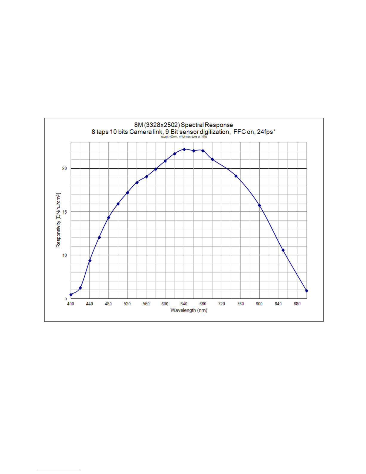
Responsivity
The responsivity graph describes the sensor response to different wavelengths of light (excluding lens
and light source characteristics).
The quantum efficiency (QE) graph describes the fraction of photons at each wavelength that contribute
charge to the pixel.
Figure 1: Spectral Responsivity
Teledyne DALSA 03-032-20107-01

12 Falcon2 4M, 8M, and 12M Camera User's Manual
Feature / Specification
Unit
MIN
TYP
MAX
Notes
Dark Pixel Definition absolute output level
DN
> 500
4 frame average
Dark Pixel Count
max #/ die
50
Light Pixel Definition deviates from frame
average
%
± 30
4 frame average image
for scene & dark correction
Average Frame
Output Level
% SAT
40
50
60
illuminated with diffused
light source on production tester
Tolerated Count
max #/ die
50
Die Cluster Defect
Definition
defects/ kernel
2 / 3x3
≤ 5 / 3x3
Detection Threshold
- Groups of
dark and light
pixels
combined dark & light pixel defects
Tolerated Count
max #/ die
7
based on estimation
algorithm in production tester
Die Spot Defect
Definition
defects/ kernel
6 / 3x3
Detection Threshold
Groups of
dark and light
pixels
combined dark & light pixel defects
Tolerated Count
max #/ die
- 0
Glass Spot Defect
Definition
defects/ kernel
8 / 3x3
8 / 3x3
illuminated with aperture
(collimated) light source on production
tester
Detection Threshold
% of ave.
± 8
4 frame average - any
pixel outside +/ - 8% of average
Tolerated Count
max #/ die
1
1 spot of 9 pixels
allowed; no limit on spots below 9 pixels
Column Defect
Definition
defects/ kernel
> 8 / 1x12
Column Defect Count
max #/ die
0 Row Defect Definition
defects/ kernel
> 8 / 12x1
Row Defect Count
max #/ die
0
Sensor Cosmetic Specifications
The following table lists the current cosmetic specifications for the Teledyne DALSA sensor used in the
Falcon2 series.
Table 5: Sensor Cosmetic Specifications
03-032-20107-01 Teledyne DALSA
Falcon2 4M, 8M, and 12M Camera User's Manual 13
Definition of Blemishes
Dark pixel defect: Pixel whose signal, in dark, exceeds 500 DN.
Light pixel defect: Pixel whose signal, at nominal light (illumination at 50% of the linear range), deviates
more than ±30% from its neighboring pixels.
Cluster defect: A grouping of at most 2 to 5 pixel defects within a sub-area of 3*3 pixels.
Die Spot defect: A grouping of 6 or more pixel defects within a sub-area of 3*3 pixels.
Glass Spot defect: A grouping of 9 pixel defects within a sub-area of 3*3 pixels.
Column defect: A column that has more than 8 defect pixels in a 1*12 kernel.
Row defect: A row that has more than 8 defects in a 12*1 kernel.
Test conditions Temperature: 40°C.
Integration Time: 12ms.
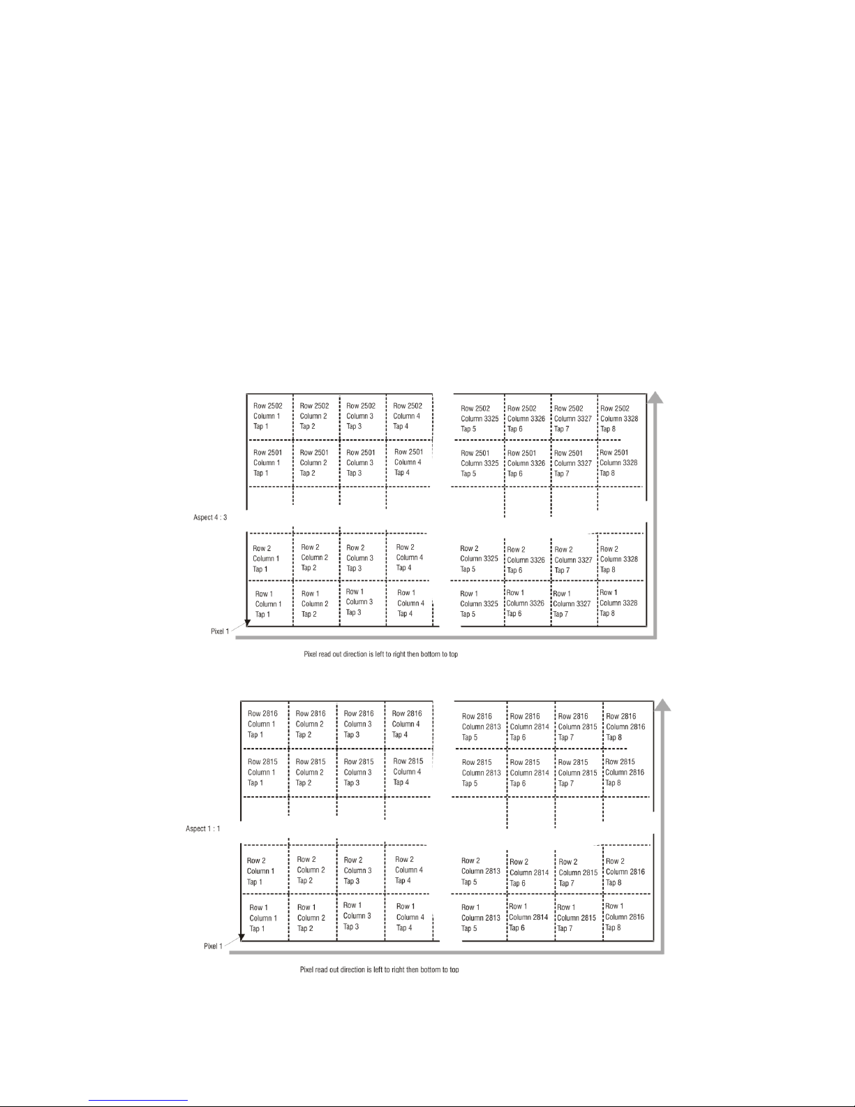
Sensor Block Diagram and Pixel Readout
Figure 2: 8 Tap Camera Link Configuration Sensor Block Diagram. Aspect Ratio 4 : 3.
Figure 3: 8 Tap Camera Link Configuration Sensor Block Diagram. Aspect Ratio 1 : 1.
Teledyne DALSA 03-032-20107-01
14 Falcon2 4M, 8M, and 12M Camera User's Manual
Note: As viewed from the front of the camera without lens.
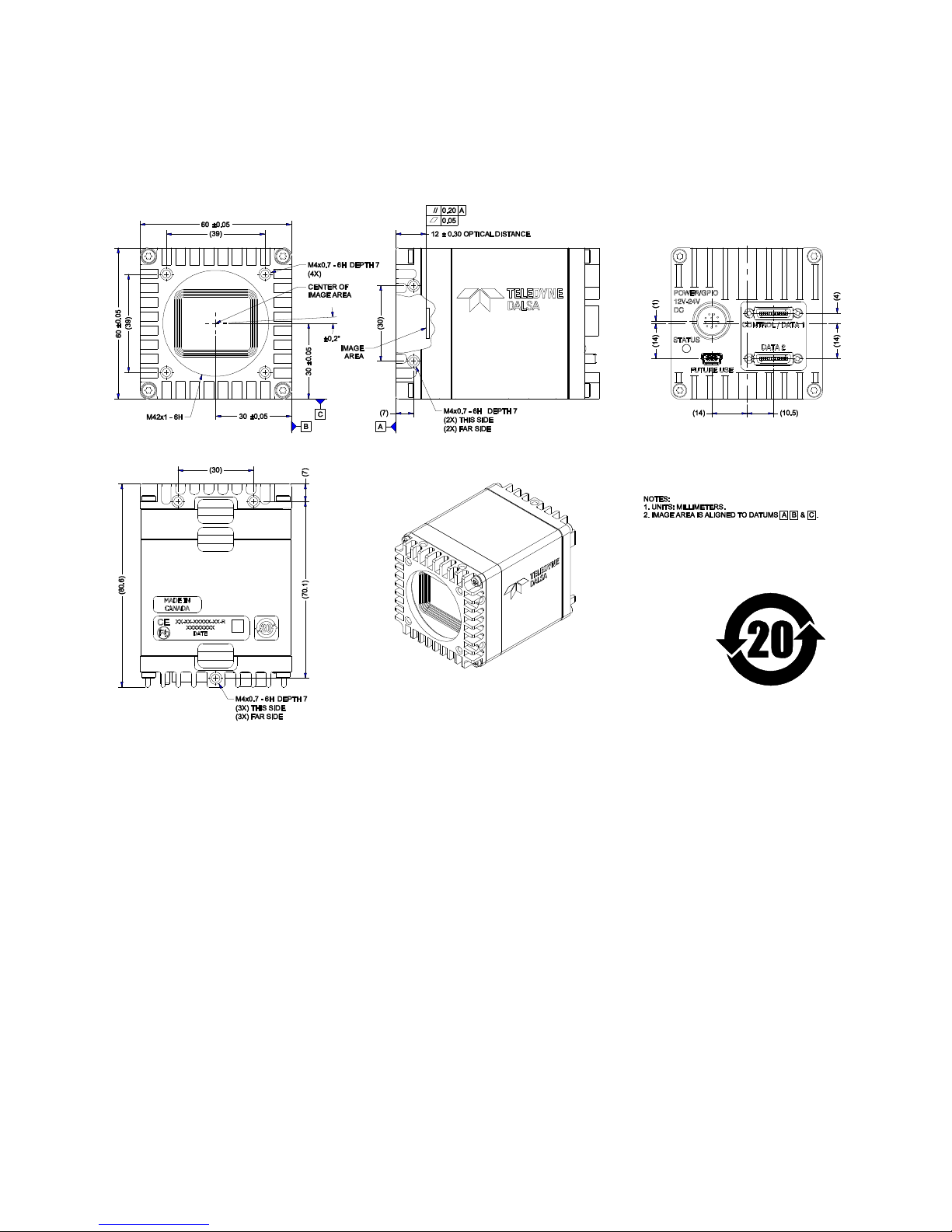
Mechanicals
Figure 4: Camera Mechanical
03-032-20107-01 Teledyne DALSA

Falcon2 4M, 8M, and 12M Camera User's Manual 15
3. Software and Hardware Setup
Minimum System Requirements
To achieve best system performance, the following minimum requirements are recommended:
High bandwidth frame grabber recommended, e.g. DALSA PX8 Full Camera link frame grabber (Part
# OR-X8CO-XPF00).
PCI x8 slot.
Operating system: Windows XP 32-bit.
Setup Steps: Overview
Take the following steps in order to setup and run your camera system. They are described briefly below
and in more detail in the sections that follow.
1. Install and Configure Frame Grabber, Graphics Card, and GUI
If your host computer does not have a PX8 full Camera link frame grabber and supporting PCIe x8
graphics card installed , then you need to install them.
We recommend the X64 Xcelera-CL PX8 frame grabber or equivalent, described in detail on the
teledynedalsa.com site here. Follow the m an u factu rer ’s in stallation in str u ctions.
A Gen ICam™ comp lian t XML d evice description file is em b edd ed w ithin th e Falcon 2 firm w are allowin g
GenICam ™ com p liant ap p lication to k n ow the cam era’s cap abilities imm ed iately after con n ection.
Installing Sap eraLT gives you access to th e Cam Exper t GUI, a GenICa m ™ com pliant ap p lication .
2. Connect Power and Camera Link Cables
Connect a power cable from the camera to a +12 VDC to +24 VDC (± 5%) power supply. Note:
11.6 V minimum.
Connect the Camera link cables from the camera to the computer.
3. Establish communicating with the camera
Start the GUI and establish communication with the camera. Refer to page 17 for a description on
communicating with the camera.
4. Check camera LED, settings and test pattern
Ensure the camera is operating properly by checking the LED, the current, active settings, and by
acquiring a test pattern.
5. Operate the Camera
At this point you will be ready to start operating the camera in order to acquire images, set camera
functions, and save settings.
Teledyne DALSA 03-032-20107-01
 Loading...