


4700 Refrigerated
Sampler
This pocket guide is not intended to replace
the instruction manual. Read the instruction
manual thoroughly before operating the
sampler.
COPYRIGHT © 2003 by
Teledyne Isco, Inc.,
4700 Superior St.,
Lincoln, Nebraska, U.S.A. 68504
Phone: (402) 464-0231
Toll Free: (800) 228-4373
FAX: (402) 465-3022
Part #69-4703-085
Released: January 10, 2007


4700 Refrigerated
Sampler
Table of Contents
1. Introduction
1.1 Features . . . . . . . . . . . . . . . . . . . . . . . 1-1
1.2 Specifications . . . . . . . . . . . . . . . . . . . 1-6
2. Installation
2.1 4700 Sampler Installation Overview 2-1
2.2 Positioning the Sampler . . . . . . . . . . 2-1
2.3 Installing a Bottle Kit . . . . . . . . . . . . 2-5
2.3.1 Installing the Distributor
Arm and Discharge Tube . . . . 2-8
2.3.2 24 Bottles . . . . . . . . . . . . . . . 2-10
2.3.3 4 Bottles . . . . . . . . . . . . . . . . 2-12
2.3.4 2 Bottles . . . . . . . . . . . . . . . . 2-12
2.3.5 1 Bottle . . . . . . . . . . . . . . . . . 2-14
2.4 Attaching the Suction Line . . . . . . . 2-16
2.4.1 Vinyl Suction Line . . . . . . . . 2-17
2.4.2 FEP-lined Suction Line . . . . 2-19
2.5 Attaching a Strainer . . . . . . . . . . . . 2-19
2.5.1 Alternative to Strainers . . . . 2-22
2.5.2 Maximum Unanchored
2.6 Routing the Suction Line and
2.7 Connecting the Sampler to
Depth . . . . . . . . . . . . . . . . . . . 2-22
Strainer . . . . . . . . . . . . . . . . . . . . . . 2-23
External Devices . . . . . . . . . . . . . . . 2-23
2.7.1 Standard Isco Instrument
Connections . . . . . . . . . . . . . . 2-25
2.7.2 Other Device Connections . . 2-25
iii

2.8 Connecting Power . . . . . . . . . . . . . . 2-30
2.9 Configuring and Programming the
Sampler . . . . . . . . . . . . . . . . . . . . . . 2-31
2.10 Locking the Sampler . . . . . . . . . . . . 2-31
3. Programming
3.1 Control Panel Description . . . . . . . . . 3-1
3.2 Getting Started . . . . . . . . . . . . . . . . . 3-3
3.3 Configuring the Sampler . . . . . . . . . . 3-4
3.3.1 Set Clock . . . . . . . . . . . . . . . . . 3-5
3.3.2 Bottle and Sizes . . . . . . . . . . . 3-5
3.3.3 Suction Line . . . . . . . . . . . . . . 3-6
3.3.4 Liquid Detector . . . . . . . . . . . . 3-7
3.3.5 Flow Mode Sampling . . . . . . . 3-9
3.3.6 Enable Pin . . . . . . . . . . . . . . . 3-10
3.3.7 Refrigeration . . . . . . . . . . . . . 3-11
3.3.8 Output Pins . . . . . . . . . . . . . . 3-12
3.3.9 Tubing Life . . . . . . . . . . . . . . 3-14
3.3.10 Program Lock . . . . . . . . . . . . 3-16
3.3.11 Language . . . . . . . . . . . . . . . . 3-17
3.3.12 System IDs . . . . . . . . . . . . . . 3-18
3.3.13 Run Diagnostics . . . . . . . . . . 3-19
3.3.14 Exit Configuration . . . . . . . . 3-19
3.4 Sampling Program Overview . . . . . 3-19
3.5 Programming Steps . . . . . . . . . . . . . 3-26
3.5.1 Pacing . . . . . . . . . . . . . . . . . . 3-26
3.5.2 Sample Every __ Hours,
__ Minutes . . . . . . . . . . . . . . . 3-27
3.5.3 Sample Every __ Pulses . . . . 3-27
3.5.4 __ Bottles per Sample Event 3-31
3.5.5 Switch on Time or Number
of Samples . . . . . . . . . . . . . . . 3-32
3.5.6 Switch Bottles Every
__ Hours, __ Minutes . . . . . . 3-32
3.5.7 First Switch Time . . . . . . . . . 3-32
3.5.8 __Samples per Bottle . . . . . . 3-32
3.5.9 Run Continuously? . . . . . . . . 3-34
3.5.10 Enter Sample Volume
Use Defined Sample . . . . . . . 3-34
iv

Table of Contents
3.5.11 Volumes Dependent
on Flow? . . . . . . . . . . . . . . . . 3-35
3.5.12 Sample Volume __ ml . . . . . . 3-36
3.5.13 Flow Pulses, Analog Input . . 3-36
3.5.14 10 ml for Every __ Pulses . . . 3-36
3.5.15 Sample Volume at
20 mA: __ ml . . . . . . . . . . . . . 3-37
3.5.16 __ Composite Samples . . . . . 3-37
3.5.17 Suction Head . . . . . . . . . . . . . 3-38
3.5.18 No Delay to Start
Set Start Time . . . . . . . . . . . 3-39
3.5.19 First Sample At: . . . . . . . . . . 3-40
3.5.20 Start Flow Count At: . . . . . . 3-40
3.5.21 Maximum Run Time
3.6 Programming Examples . . . . . . . . . 3-41
__ Hours . . . . . . . . . . . . . . . . 3-40
3.6.1 Defining the Sample Volume 3-41
3.6.2 Time Paced Sampling
Program . . . . . . . . . . . . . . . . 3-44
3.6.3 Flow Paced Sampling
Program . . . . . . . . . . . . . . . . 3-47
3.6.4 Flow-proportional Constant
Time Variable Volume
Program . . . . . . . . . . . . . . . . 3-51
4. Operation
4.1 Start a Sampler Program . . . . . . . . . 4-1
4.1.1 Start Time Delay . . . . . . . . . . 4-2
4.1.2 The Run State . . . . . . . . . . . . . 4-3
4.1.3 Completed Program . . . . . . . . 4-4
4.2 Pause or Stop a Running Program . . 4-4
4.3 Post Sampling Activities . . . . . . . . . . 4-5
4.3.1 View the Log . . . . . . . . . . . . . . 4-5
4.3.2 Remove Sample Bottles . . . . 4-10
4.4 Grab Samples . . . . . . . . . . . . . . . . . . 4-11
4.5 Calibrate Sample Volumes . . . . . . . 4-12
4.6 Operate the Pump Manually . . . . . . 4-15
v

5. Maintenance
5.1 Periodic Maintenance Checklist . . . . 5-1
5.1.1 Pump Inspection . . . . . . . . . . . 5-2
5.1.2 Pump Tube Replacement . . . . 5-4
5.1.3 Cleaning the Pump Rollers . . 5-7
5.1.4 Cleaning the Pump Housing . 5-7
5.1.5 Cleaning or Replacing
Wetted Parts . . . . . . . . . . . . . . 5-7
5.1.6 Sampler Cleaning Guidelines 5-9
vi
4700 Refrigerated
Sampler
Section 1 Introduction
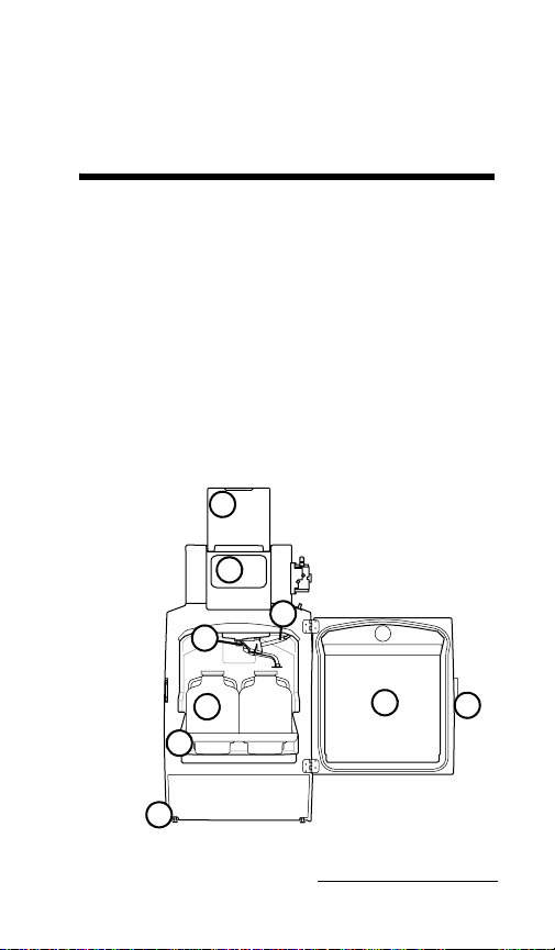
1.1 Features
The 4700 Series sampler features are identified
in Figures 1-1 through 1-3 and described in
Table 1-1.
1
2
3
4
5
6
9
Figure 1-1 4700 Sampler features (Front)
7
8
1-1
4700 Refrigerated Sampler
10
11
11
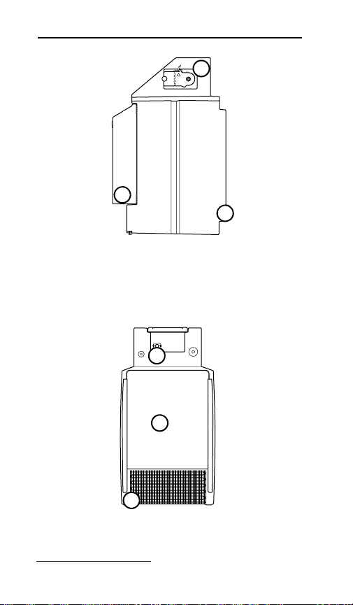
Figure 1-2 4700 Sampler features (Side)
12
13
14
Figure 1-3 4700 Sampler features (Back)
1-2
Section 1 Introduction
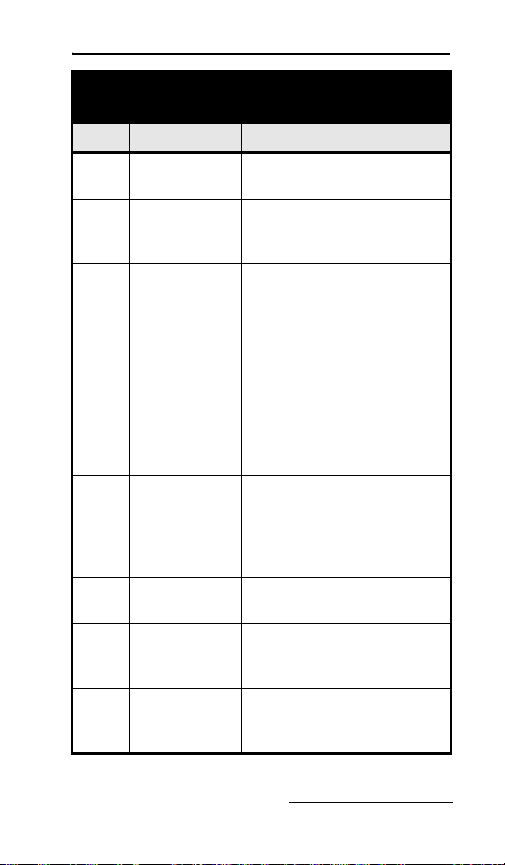
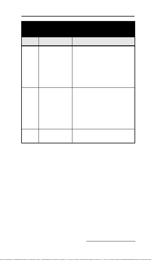
Table 1-1 4700 Sampler Features
Item Name Description
1 Control
Panel Cover
2 Control
Panel
3 Discharge
Tube
4 Distributor
Arm
5 Bottles Hold the collected
6 Bottle
Locator
Rack
7 Refrigerator
Door
Protects the control panel
display and keypad.
Supports user control and
programming of sampler
operation.
Carries liquid to the
sample bottle. For 24, 4, 2,
and 10 liter one-bottle
configurations, the
discharge tube is routed
through the distributor
arm. For the 20 liter
one-bottle configuration
the discharge tube is
routed directly into the
bottle.
Directs collected liquids to
the bottle. Movement of
the distributor is controlled
by user-specified program
settings.
samples.
Positions the bottles under
the distributor.
Protects the collected
samples inside the
refrigerated compartment.
1-3
4700 Refrigerated Sampler
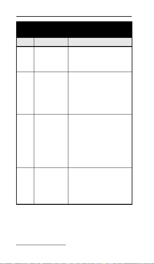
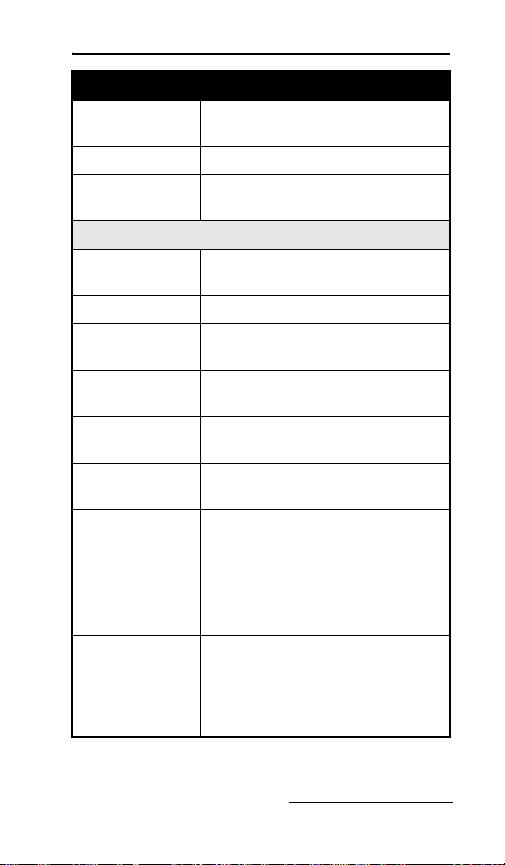
Table 1-1 4700 Sampler Features
(Continued)
Item Name Description
8 Latch Secures the door. The
9Level
Adjustment
Feet
10 Liquid
Detector and
Pump
11 Lift Points If you must lift the sampler,
latch mechanism may be
locked with a
user-supplied padlock.
The sampler includes two
level adjustment feet at the
front of the sampler. Use
these to keep the bottle
rack or locating deck level
inside the refrigerated
compartment.
The non-wetted liquid
detector senses when the
liquid is at the pump to
determine head height
and sample volumes. The
peristaltic pump collects
sample liquid and
performs suction line
rinses.
it can be safely handled at
these points. Lifting must
be done by two people,
one on each side, with the
door closed and latched.
1-4
Section 1 Introduction
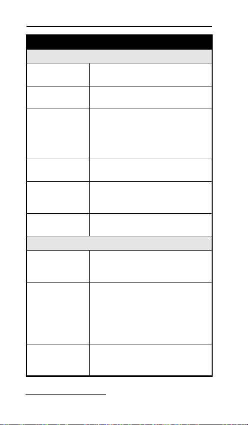
Table 1-1 4700 Sampler Features
(Continued)
Item Name Description
12 External
Device
Connection
13 Refrigeration
Assembly
14 AC Mains
Line Cord
Supports connections to
external devices such as a
flow meter for sample
pacing and enable signals,
and connection to a
personal computer for
data collection.
Modular,
corrosion-resistant
refrigeration assembly
cools the refrigerated
compartment to a
user-selected temperature
of 1 to 9°C (34 to 48°F).
Connects to AC power
source.
1-5

4700 Refrigerated Sampler
1.2 Specifications
Table 1-2 Specifications
General
Size
(H×W×D):
Weight
(empty):
Bottle
Configurations:
Refrigerator
Body:
Powe r
Requirements:
Installation
Category:
Pollution
Degree:
130 × 72 × 84 cm
51 × 28 × 33 in
72 kg
159 lb
12 configurations available:
24, 1-liter PP or 350 ml glass;
4, 10-liter PE or glass;
2, 10-liter PE or glass;
1, 20-liter PE or glass;
1, 10-liter PE or glass;
24 ProPaks, 1-liter wedge;
1 ProPak, 10-liter round
Linear low-density polyethylene
(LLDPE)
100 VAC ±10%, 50 Hz:
Running current 1.4 amperes
Stalled current 21.3 amperes
115 VAC ±10%, 60 Hz:
Running current 1.4 amperes
Stalled current 21.3 amperes
230 VAC ±10%, 50 Hz:
Running current 0.82 amperes
Stalled current 17 amperes
II
3
1-6
Section 1 Introduction
Table 1-2 Specifications (Continued)
Maximum
Altitude:
Humidity: 0 to 100%
Operational
Temperature:
Pump
Intake Suction
Tubing Length:
Material: Vinyl or FEP-lined polyethylene
Inside
Diameter:
Pump Tubing
Life:
Maximum
Suction Lift:
Ty pi c a l
Repeatability:
Typical Line
Velocity at
Head Height:
Liquid
Presence
Detector:
2,000 meters
–29 to 49 °C
–20 to 120 °F
1 to 30 m
3 to 99 feet
9 mm
3
/8 inch
Typically 1,000,000 pump
counts.
8.5 m
28 feet
±5 ml or ±5% of the average
volume in a set.
0.9 m: 0.91 m/s
3.1 m: 0.87 m/s
4.6 m: 0.83 m/s
3 ft: 3.0 ft/s
10 ft: 2.9 ft/s
15 ft: 2.7 ft/s
Non-wetted, non-conductive
sensor detects when liquid
sample reaches the pump to
automatically compensate for
changes in head heights.
1-7
4700 Refrigerated Sampler
Table 1-2 Specifications (Continued)
Controller
Enclosure
Rating:
Program
Memory:
Flow Meter
Signal Inputs:
Digital Alarms: 4 programmable outputs; 5
Number of
Composite
Samples:
Internal Clock
Accuracy:
Software
Sample
Frequency:
Sampling
Modes:
Programmable
Sample
Vol um es:
IP67
NEMA 4X, 6
Non-volatile ROM (Flash)
5 to 15 volt DC pulse or 25
millisecond isolated contact
closure for Isco flow meters.
4-20 mA input for non-Isco flow
meters.
VDC, 100 mA
Programmable from 1 to 999
samples.
1 minute per month, typical
1 minute to 99 hours 59 minutes,
in 1-minute increments. 1 to
9,999 flow pulses.
Constant Time, constant volume
Variable time, constant volume
Constant time, variable volume
(Variable time and variable
volume modes are controlled by
an external flow meter signal)
10 to 9,990 ml in 1 ml
increments.
1-8

Section 1 Introduction
Table 1-2 Specifications (Continued)
Sample
Retries:
Rinse Cycles: Automatic rinsing of suction line
Controller
Diagnostics:
If no sample is detected, up to 3
attempts; user selectable.
up to 3 rinses for each sample
collection.
Tests for RAM, ROM, pump,
display, and electrical
components.
1-9

4700 Refrigerated Sampler
1-10

4700 Refrigerated
Sampler
Section 2 Installation
2.1 4700 Sampler Installation Overview
The following sections provide general
instructions for placing the sampler into
operation. In typical applications, the steps are:
1. Position the sampler. (Section 2.2)
2. Install a bottle kit. (2.3)
3. Attach the suction line. (2.4)
4. Attach a strainer. (2.5)
5. Route the suction line and strainer. (2.6)
6. Connect external instruments. (2.7)
7. Connect power. (2.8)
8. Configure and program the sampler. (2.9)
9. Lock the sampler. (2.10)
2.2 Positioning the Sampler
There are a few considerations when selecting a
site for the sampler. The foremost concern
should be personal safety.
2-1
4700 Refrigerated Sampler
The installation and use of this product may
subject you to dangerous working conditions
that can cause you serious or fatal injuries.
Take any necessary precautions before entering
the worksite. Install and operate this product in
accordance with all applicable safety and
health regulations, and local ordinances.
WAR NING
If this product is used in a manner not specified
in this manual, the protection provided by the
equipment may be impaired.
WAR NING
This product has not been approved for use in
hazardous locations as defined by the National
Electrical Code.
WAR NING
The sampler is heavy. When lifting, use a
two-person lift at the points identified in Table 1-1.
When possible, move the sampler using a
two-wheeled hand cart from the left or right side.
To prevent damage to the refrigeration system, do
not tip the sampler more than 45°.
Dangerous locations – If you must enter a
manhole, confined space, or other dangerous
location to install the suction line and strainer,
observe standard safety precautions. Refer to
2-2

Section 2 Installation
Appendix B of the Installation and Operation
guide for a discussion of safety considerations.
Support – The sampler should be installed on
a surface capable of safely supporting the
sampler, full liquid containers, and personnel.
AC Power – The mains line cord is the
disconnect device should you need to remove
power. Therefore, the electrical power outlet
should be accessible.
Environmental – The sampler is designed for
outdoor use. Refer to Table 1-2 for
environmental specifications. When possible,
avoid subjecting the sampler to chemical
attacks and direct sunlight.
Avoid submersion – Although the control
panel will resist damage (rated NEMA 4x, 6;
IP 67), the refrigerator system and bottle
compartment cannot prevent the liquid from
entering. Liquid entering the refrigeration
system might permanently damage the
sampler; liquid entering the bottle
compartment might contaminate the collected
samples. Liquid entering the electrical
compartment for the refrigeration system
might result in a short circuit and possible
shock hazard.
Liquid sample collection point – It is best to
keep the distance between the sampler pump
and the collection point as short as possible.
The shorter distance will increase pumping
efficiency and pump tubing life. Also, the pump
inlet should be located above the liquid surface.
Gravity will aid suction line rinses and allow
2-3

4700 Refrigerated Sampler
the line to drain, thereby reducing the
possibility of sample cross-contamination. Refer
to Table 1-2 for maximum suction line lengths
and suction head heights.
Security – The location may need to provide
some degree of security to prevent tampering or
vandalism.
Accessibility – The sampler must be installed
in a location where personnel can easily
exchange bottles and perform routine service.
The sampler requires about 2600 square
centimeters (925 in
2
) of floor space. Additional
space must be allowed in front of the sampler,
at its left and right sides, and above the
sampler. Do not block access to these areas.
Obstructions will make routine servicing
activities difficult or impossible.
The back of the sampler may be placed against
a wall as long as air at the bottom of the
refrigerator can flow freely to surrounding air.
Unrestricted air flow behind and around the
sampler will keep the refrigeration system
working efficiently.
Level surface – The sampler should be placed
on a level surface and the feet on the
refrigerator body should be adjusted to prevent
tipping or spills. If the sampler is not level, the
sample liquid may miss the bottle mouth.
To level the sampler, place a bubble level on the
bottle rack or locating base, then adjust the
feet. For one-bottle configurations, place the
bubble level on the side rails of the refrigerated
compartment.
2-4
Section 2 Installation
CAUTION
Do not tip the sampler on its side or back. Tipping
the sampler more than 45° might cause oil to run
into the compressor inlet, which can permanently
damage the sampler.
2.3 Installing a Bottle Kit
The 4700 sampler can hold 1, 2, 4, and 24
bottles. Each of these bottle configurations are
supplied as a kit (see Table 2-1), which is
normally ordered with the sampler or when you
desire to change the bottle configuration.
Table 2-1 Bottle Kits
Part Number Description
68-4700-003 24-bottle Configuration. Includes
68-4700-004 24-bottle Configuration. Includes
68-4700-017 24-Container ProPak
24 polypropylene 1-liter wedge
shaped bottles with caps,
retaining ring, bottle rack and
two discharge tubes.
24 glass 350-ml round bottles
with PTFE lined caps, retaining
rings, bottle rack and two
discharge tubes.
Configuration. Includes 25
holders, 100 bags, retaining
ring, bottle rack and instruction
sheet.
2-5
4700 Refrigerated Sampler
Table 2-1 Bottle Kits (Continued)
Part Number Description
68-4700-005 4-bottle Configuration. Includes
68-4700-006 4-bottle Configuration. Includes
68-4700-007 2-bottle Configuration. Includes
68-4700-008 2-bottle Configuration. Includes
68-4700-009 1-bottle Configuration. Includes
68-4700-010 1-bottle Configuration. Includes
four polyethylene 10-liter round
bottles with caps, locating base
and two discharge tubes.
four glass 10-liter round bottles
with PTFE lined caps, locating
base and two discharge tubes.
two polyethylene 10-liter round
bottles, locating base, caps and
two discharge tubes.
two glass 10-liter round bottles
with PTFE lined caps, locating
base, and two discharge tubes.
one polyethylene 2.5-gallon
(10-liter) round bottle, locating
base, two caps and two
discharge tubes.
on glass 2.5-gallon (10-liter)
round bottle, two PTFE lined
caps, locating base, and two
discharge tubes.
2-6
Section 2 Installation
Table 2-1 Bottle Kits (Continued)
Part Number Description
68-4700-018 Single ProPak Configuration for
68-4700-011 1-bottle Configuration. Includes
68-4700-012 1-bottle Configuration. Includes
If you have selected a multi-bottle kit, first
install the distributor arm and discharge tube
(Section 2.3.1), then refer to the instructions for
your selected bottle configuration:
• 24 Bottle configurations – section 2.3.2
• 4 Bottle configurations – section 2.3.3
• 2 Bottle configurations – section 2.3.4
4700 and 6700 Series FR
Refrigerated Sampler. Includes
one composite ProPak holder
with cap, 100 ProPak bags, two
discharge tubes and an
instruction sheet.
one polyethylene 20-liter round
bottle, two caps and two
discharge tubes.
one glass 20-liter round bottle,
two PTFE lined caps and two
discharge tubes.
If you have selected a single (composite) bottle
kit, refer to the instructions in section 2.3.5.
For first-time use of the sampler, or if you have
changed the bottle kit, be sure to configure the
software for the new bottle kit (section 3.3.2).
2-7
4700 Refrigerated Sampler
2.3.1 Installing the Distributor Arm and
Discharge Tube
The distributor arm ships with the sampler
installed on its mounting shaft inside the
refrigerator (Figure 2-1). It is generally easier
to install the discharge tube with the arm
removed, then you can reinstall the distributor
arm. To do so:
1. Remove the knurled nut that secures the
distributor arm.
Figure 2-1 Installing the distributor arm and
discharge tube
2. Pull the distributor arm downward to
remove it from the keyed shaft.
3. Thread the discharge tube through the body
of the distributor arm.
4. Insert the end of the discharge tube into the
outlet hole on the distributor arm.
2-8
Section 2 Installation
CAUTION
The discharge tube should not extend below the
hole in the distributor arm. This could cause the
distributor to fail if the excess tubing catches a
bottle.
5. Pull on the loose end of the discharge tube
to remove any slack. The tube should follow
the contour of the distributor arm.
6. Push the distributor arm up onto the keyed
shaft and secure it with the knurled nut.
7. Push the loose end of the discharge tube
onto the bulkhead fitting in the top-front
corner of the refrigerator.
8. Inspect the discharge tube:
CAUTION
An incorrectly installed discharge tube can cause
the distributor arm to fail. It can also
cross-contaminate samples. To prevent these
problems, inspect the discharge tube as described
in the following steps.
a. Manually rotate the arm to make sure
that the tube does not obstruct its
movement. If the tube obstructs arm
movement, re-route the discharge
tubing.
b. The discharge tube must slope
downward from the bulkhead fitting to
the arm throughout the range of arm
motion. Otherwise, liquid might pool in
2-9

4700 Refrigerated Sampler
the tube and cross-contaminate samples.
Note that the discharge tube has a
natural curve. Should the tube create a
low spot where liquid can pool, twist the
end of the tube connected to the
bulkhead fitting so that the natural
curve holds the tube in a downward
sloping position. Then, retest the tube at
other arm positions.
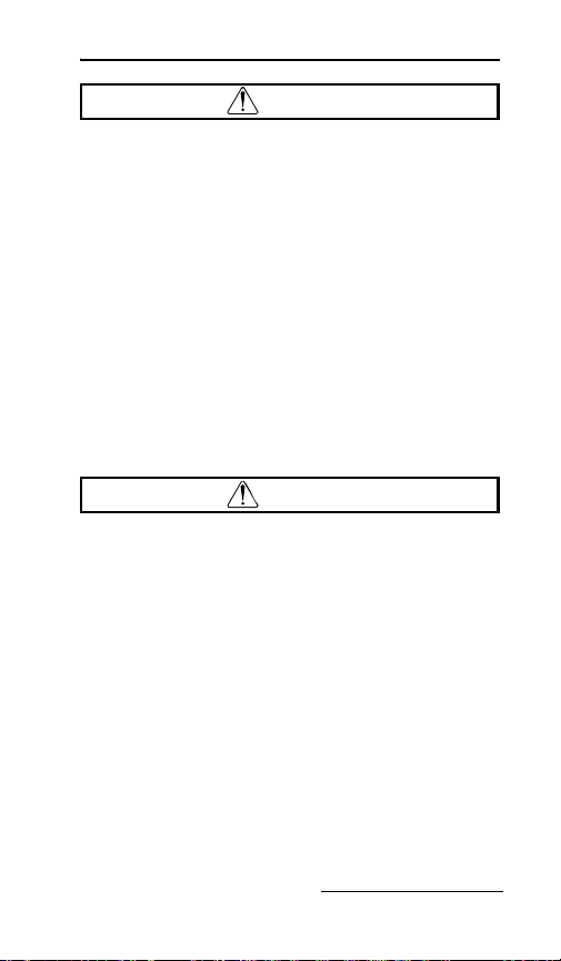
2.3.2 24 Bottles
The 24 bottle configurations use a rack to hold
and align the containers. To install the bottles
in the refrigerator using the rack:
1. Place the uncapped bottles in the rack.
2. If you are using 350 ml glass bottles,
compress the retaining ring and place it in
the center of the bottles. Release the ring
and the outward force of the ring will secure
the bottles. (The polypropylene and
®
ProPak
bottles do not use a retaining ring.)
Note
Bottles caps can be stored in the center of the bottle
rack.
3. Locate the back of the rack (arrow, Figure
2-2). This end has a notch that fits a key on
the rear wall of the refrigerator.
4. Lift and insert the back of the rack into the
refrigerated compartment.
2-10
Section 2 Installation
Figure 2-2 Insert the keyed end first so that it
faces the back of the
refrigerated compartment
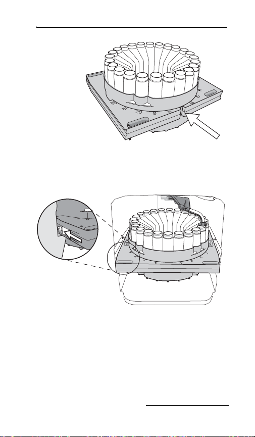
Figure 2-3 The 24-bottle rack is held in place
by a latch on the left side
2-11
4700 Refrigerated Sampler
Note
There are four metal guides along the sidewall of the
refrigerator, two on each side. The front two guides fit
along the left and right sides of the rack. The back two
guides run along the top of the rack to prevent the rack
from tipping forward.
5. Slide the rack along the guides. Push the
rack in until the left-side latch (inset,
Figure 2-3) secures the rack.
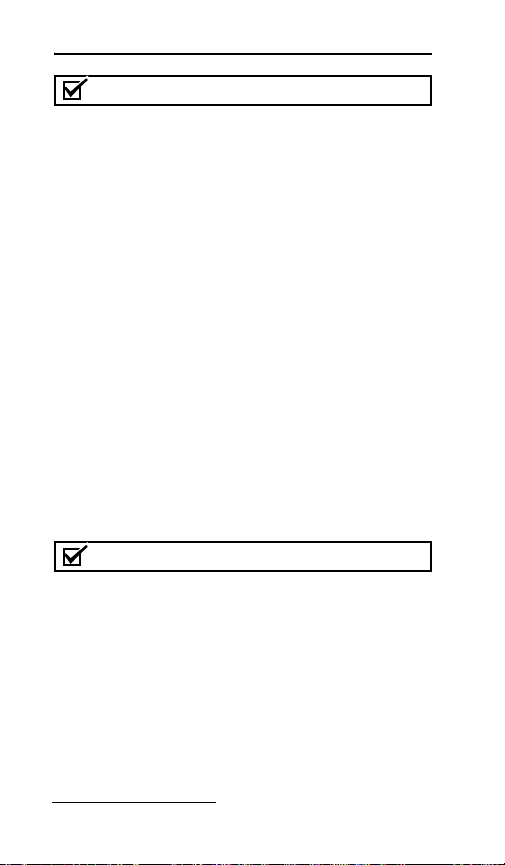
2.3.3 4 Bottles
The four bottle configuration uses a locating
base to hold and align the bottles. To install the
base and bottles:
1. Slide the locating base into the bottom of
the refrigerated compartment (Figure 2-4).
Note that the arrow must be pointing
toward the back of the refrigerator.
2. Insert the four uncapped bottles into the
numbered holes in the locating base.
Note
Bottle caps can be stored between the bottles.
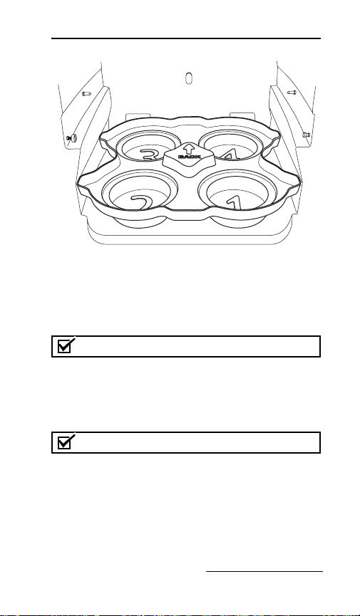
2.3.4 2 Bottles
The two bottle configuration uses a locating
base to hold and align the bottles. To install the
base and bottles:
1. Slide the locating base into the bottom of
the refrigerated compartment (Figure 2-4).
Note that the arrow must be pointing
toward the back of the refrigerator.
2-12
Section 2 Installation
Figure 2-4 Installing the locating base
2. Insert the two uncapped bottles into the
holes numbered “1” and “2” in the locating
base.
Note
When the sampler controller is configured for two
bottles (section 3), samples will only be distributed to
bottles 1 and 2. If you place the bottles in positions 3 or
4 the liquid will miss the bottle.
Note
Bottle caps can be stored between the bottles.
2-13

4700 Refrigerated Sampler
2.3.5 1 Bottle
If your one-bottle configuration has a 10 liter
(2.5 gallon) polyethylene, glass, or ProPak
bottle, use a locating base to hold and align the
bottle. If your one-bottle configuration has a 20
liter (5 gallon) glass or polyethylene bottle,
simply place the bottle in the center of the
refrigerator; no rack or locating base is
required.
Refer to the instructions for your bottle size.
10 liter bottle – To install the locating base
and 10 liter bottle:
1. Slide the locating base into the bottom of
the refrigerated compartment (Figure 2-4).
Note that the arrow must be pointing
toward the back of the refrigerator.
2. Insert the bottle into the hole numbered “1”
in the locating base.
Note
When the sampler controller is configured for a single
10 liter bottle (section 3), samples will only be
distributed to bottle 1. If you place the bottle in any other
position liquid will miss the bottle.
20 liter bottle – To install the 20 liter bottle:
The distributor arm should be removed to
prevent it from being an obstruction while you
replace the bottle. To remove the arm:
1. Remove the knurled nut that secures the
distributor arm.
2. Pull the distributor arm downward to
remove it from the keyed shaft.
2-14

Section 2 Installation
3. Store the arm in a safe location for future
use.
Then install the bottle:
4. Screw the cap with a hole onto the bottle.
5. Place the bottle in the center of the
refrigerator.
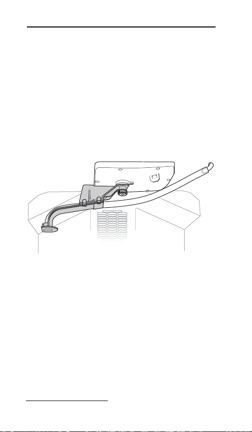
6. Feed the discharge tube into the hole (see
Figure 2-5).
7. Connect the other end of the discharge tube
to the bulkhead fitting at the top-front
corner of the refrigerator.
Figure 2-5 One 20 liter bottle configuration
with discharge tube through
the bottle cap
2-15

4700 Refrigerated Sampler
The discharge tube must slope downward from
the bulkhead fitting to the bottle. Otherwise,
liquid might pool in the tube and
cross-contaminate samples.
Note that the discharge tube has a natural
curve. Should the tube create a low spot where
liquid can pool, twist the end of the tube
connected to the bulkhead fitting so that the
natural curve holds the tube in a downward
sloping position.
2.4 Attaching the Suction Line
The suction line is the tubing from the
sampling point to the pump tube inlet. The
sampler uses a
lengths from 3 to 99 feet. Teledyne Isco offers
vinyl or FEP-lined suction lines. The FEP-lined
tubing has a polyethylene jacket to protect it
from kinks and abrasions.
Note
The vinyl suction line contains a very low parts-permillion level of phenols. If phenol content affects your
sample analysis, use the FEP-lined suction line.
Teledyne Isco ships suction line in standard
lengths of 3.0 m (10 ft) or 7.6 m (25 ft). Either
length should be cut to the shortest length
feasible for the installation. When installed, the
line should run the shortest possible distance
from the collection point to the pump,
preferably with a gradual upward slope. Excess
suction line should be cut, not coiled. Coiled
3
/8-inch ID suction line of
2-16

Section 2 Installation
suction line will hold liquid between sample
events which could cross-contaminate samples
or freeze in cold climates. If the standard
lengths are too short, or if you are cutting
compatible
3
/8-inch ID suction line from a bulk
spool, you can use lengths up to 30 m (99 ft).
When accurate, repeatable sample volumes are
important, use care to cut the suction line to
the correct increments:
• When the sampler is using metric units
of measure, cut the line in 0.1 m
increments. For instance, cut 4.2 m, not
4.26 m.
• When using English units of measure,
cut the line in increments of 1 foot.
Record this cut length. Later, you will enter this
value in the SUCTION LINE configuration
option (section 3).
2.4.1 Vinyl Suction Line
To attach vinyl suction line to the pump tube
(refer to Figure 2-6):
1. Locate the end of the tubing coupler with
the black clamp. Push this end of the
coupler into the upper pump tube (inlet).
2. Secure the tubing coupler by wrapping the
black clamp around the pump tube and
squeezing the finger pads together.
3. Push the vinyl suction line onto the other
end of the tubing coupler.
2-17

4700 Refrigerated Sampler
4. Secure the vinyl suction line connection by
wrapping the white clamp around the tube
and squeezing the finger pads together.
Figure 2-6 Attaching the vinyl suction line
with a tube coupler
Note
Release clamps by sliding the finger pad ends in
opposite directions until the teeth disengage
(Figure 2-7).
Figure 2-7 Releasing a tube coupler clamp
2-18

Section 2 Installation
2.4.2 FEP-lined Suction Line
Inserting a tube coupler into FEP-lined suction
line will damage the thin lining. Instead, refer
to Figure 2-8 and the instructions below to
attach FEP-lined suction line to the pump tube:
1. Slide a suitable clamp over the pump tube
inlet.
2. Push about 20 mm of the FEP-lined suction
line into the end of the pump tube.
3. Slide the clamp over the union and tighten.
Do not overtighten; this might cause the
tubing to collapse or restrict the flow.
A
B
Figure 2-8 Connecting FEP-lined suction line
(A) to pump tube (B)
2.5 Attaching a Strainer
To select the right strainer for your application,
see Table 2-2 and Figure 2-9.
To attach the strainer to the suction line,
carefully screw the strainer’s threaded
connector into the suction line. If attaching the
strainer to an FEP-lined suction line, heat the
end before threading the strainer into the line.
Warming FEP-lined tubing will make it more
pliable to avoid damage.
2-19

4700 Refrigerated Sampler
Weighted
60-9004-367
Figure 2-9 Strainers
Low Flow
69-2903-138
CPVC
60-3704-066
øB
øA
C
2-20

Section 2 Installation
N/A
15 ft
4.5 m
15 ft
4.5 m
Maximum
Unanchored Depth
C
length
B
dia.
A
Table 2-2 Strainers
22 ft
Vinyl FEP-lined
6.7 m
10.5 in
267 mm
1.25 in
32 mm
0.40 in
Routine 10 mm
stainless steel ends,
polypropylene
center
4 ft
22 ft
1.2 m
6.7 m
7.0 in
11.5 in
292 mm
178 mm
1.31 in
33 mm
14 mm
0.562 in
0.40 in
0.40 in
10 mm
Low flow 10 mm
acidic
Stainless Steel
liquids,
metals
Part Number Strainer Application dia.
60-9004-367 Weighted Strainer-
69-2903-138 Low Flow Strainer-
60-3704-066 CPVC Strainer Highly
2-21

4700 Refrigerated Sampler
2.5.1 Alternative to Strainers
When sampling from high velocity streams
with heavy suspended solids, some field
investigations suggest that more
representative samples are obtained without
the strainer. Consider attaching a short piece of
thin walled aluminum tubing to the end of the
suction line; anchor the tubing so that the inlet
opens upstream. The aluminum tubing’s thin
wall will not disturb the flow stream, and most
sample analyses disregard aluminum ions.
Under most conditions, the pre-sample line
rinse removes any debris over the tubing
entrance.
2.5.2 Maximum Unanchored Depth
Table 2-2 lists maximum unanchored depths for
each type of suction line. During a pre- or
post-sample line rinse, the suction line is filled
with air which might cause the suction line and
strainer to float. If the depth of the strainer
exceeds the listed value, securely anchor the
strainer.
Even if the maximum depth is not exceeded, it
is a good idea to anchor the suction line and
strainer when sampling from high velocity or
turbulent flow streams.
2-22

Section 2 Installation
2.6 Routing the Suction Line and Strainer
Route the suction line so that it has a
continuous slope from the liquid source to the
sampler. This helps to drain the line during
pre- and post-sample line rinses. If a suction
line exposed to freezing climates does not fully
drain, there is a risk of liquid in the suction line
becoming frozen. Frozen liquid will cause the
sample collection to fail. A warm sampling
source can usually prevent this, provided there
are no loops in the suction line. Some extreme
situations may require more protective
measures, such as insulating the suction line,
or applying heat tape.
For representative samples, place the strainer
in the main current of the flow stream, not in
an eddy or at the edge of flow. Placing a strainer
at the bottom may produce samples with excess
heavy solids and no floating materials, while
placing it at the top may produce the opposite
conditions.
2.7 Connecting the Sampler to External Devices
You can connect the sampler to an external
instrument (Figure 2-10) for a variety of
reasons. Typical reasons include:
• Receiving flow pulses from a flow meter
device for variable time or variable
volume sample collection.
2-23

4700 Refrigerated Sampler
Figure 2-10 External device connection at
rear of sampler
• Receiving an enable pin signal to enable
sampler operation once site conditions
warrant sample collection.
• Sending a three-second event mark at
the beginning of every sample collection
event.
• Receiving a linear 4-20 mA analog
representation of the flow rate for
variable time or variable volume sample
collection.
• Sending alarm signals when
user-specified sampler events occur.
These types of connections can be categorized
as Standard Isco device connections or other
device connections. Each type is discussed in
sections 2.7.1 and 2.7.2, respectively.
This rear-panel connection may also be used for
communicating with a computer for the
purpose of collecting reports. Please refer to the
2-24

Section 2 Installation
Installation and Operation Guide for more
information about this feature.
2.7.1 Standard Isco Instrument Connections
You can connect the sampler to an Isco 4100
Series flow logger or a 4200 Series flow meter.
With these Isco instruments you can:
• Receive flow pulses for variable time or
variable volume sample collection.
• Receive an enable pin signal to enable
sampler operation once site conditions
warrant sample collection.
• Send a three-second event mark at the
beginning of every sample collection
event.
• Power the flow measurement device.
To connect either of these instruments, use the
optional 7.6 m (25 ft) connect cable,
69-4704-043 (Figure 2-11).
Figure 2-11 4700 Sampler to Isco flow meter
cable
2.7.2 Other Device Connections
You can connect the sampler to receive a 4-20
mA signal from an external device, including
Isco’s 2108 and accQcomm™ analog output
modules. You can also connect the sampler to a
non-Isco device to receive flow pacing and
2-25

4700 Refrigerated Sampler
enable pin signals, to send sample event marks
and alarm signals, or to supply 12 VDC power.
All of these types of connections use the
optional unterminated connect cable, P/N
68-4700-020 (Figure 2-12). This 3 m (10 ft)
cable is unterminated at the device end to allow
wired connections to compatible circuits. Refer
to Table 2-3 for wire identification and
connection details.
Figure 2-12 4700 Sampler unterminated
connect cable
CAUTION
Risk of equipment damage. Only experienced
electronic technicians should make the connections
to an external device using cable 68-4700-020.
To connect the external device, refer to Table
2-3 and select the appropriate wires. Splice the
wires by soldering or using crimped connectors.
Trim back the tinned ends of any unused wires
and provide appropriate electrical insulation.
To complete the connection, be sure to protect it
from the environment. Running the cables
through conduit and making the connections
inside a watertight electrical box generally
provides adequate protection.
2-26

Section 2 Installation
The Isco Quick Disconnect (Q.D.) box, P/N
60-2004-228, can provide a convenient,
watertight connection to wiring from a non-Isco
device. The sealed IP67 (NEMA 4x) enclosure
contains seven terminal blocks and is equipped
with a mounting plate. The hazardous location
rating of Q.D. box does not apply when used
with an Isco sampler.
Table 2-3 Unterminated Connect Cablea
Pin Wire
Color
1 Black 12 VDC
2 White Ground Common ground
3 Green Flow
4 Blue Serial
5 Orange Event
Signal
b
Name
Powe r
Pulse
Data
Mark
Parameters/
Comments
Output: +12.5 VDC, 1
ampere maximum
Input: 25 millisecond
(minimum) pulse, +5
to +15 VDC
Output: For use with
PC connections.
Cable 69-4704-042 is
recommended. See
the Installation and
Operation guide.
Output: 3 second,
+12 VDC pulse at
beginning of sample
collection
2-27

4700 Refrigerated Sampler
Table 2-3 Unterminated Connect Cablea
(Continued)
Pin Wire
Color
6 Red Enable
7 White/Black 12 VDC Output: +12.5 VDC,
8 Red/Black Alarm 1
9 Red/White Alarm 2
10 Orange/
Black
11 Green/Black Alarm 4
12 Green/White Analog
Signal
b
Name
Pin
Parameters/
Comments
Input: Ground this
c
input (short to pin 2)
to disable sampler
operation. Leave this
input open (floating)
to collect samples.
1 ampere maximum
d
Output: 0 to +5 VDC,
100 mA maximum
d
Output: 0 to +5 VDC,
100 mA maximum
d
Alarm 3
Output: 0 to +5 VDC,
100 mA maximum
d
Output: 0 to +5 VDC,
100 mA maximum
Input: Linear current
4-20 mA
(+)
loop signal
representing
minimum flow rate at
4 mA, maximum flow
rate at 20 mA. This
input is paired with
pin 13.
2-28

Section 2 Installation
Table 2-3 Unterminated Connect Cablea
(Continued)
Pin Wire
Color
13 Blue/White Analog
14 Blue/Black Ground Common ground.
15 Black/White N/A Not used
16 Bare N/A Not used
a. All voltage levels are referenced to com-
mon ground on pins 2 and 14.
b. For color pairs, the first named color is the
predominant color; the second named color is the spiral stripe around it.
c. This pin is also used as the Serial Data In-
put for use with PC connections. Cable
69-4704-042 is recommended instead for
a serial data connection. See the Installation and Operation guide.
d. See section 3.3.8 to configure alarm con-
ditions.
Signal
b
Name
4-20 mA
(–)
Parameters/
Comments
Input: See pin 12.
Same as pin 2.
2-29

4700 Refrigerated Sampler
2.8 Connecting Power
WAR NING
Before connecting the sampler to an AC power
source, be familiar with the Electrical
Requirements listed at the front of the Installation
and Operation manual.
The factory assembles the sampler for either
100VAC/50 Hz, 115 VAC/60 Hz, or 230 VAC/50
Hz. The serial number label located inside the
refrigerator identifies the AC power
configuration of your sampler. You cannot
convert the sampler in the field without
purchasing a replacement refrigeration module.
The mains power cord for 115 VAC samplers is
equipped with a NEMA 5-15P plug for standard
North American outlets. The mains power cord
for 230 VAC samplers is equipped with an
EU-16P plug for standard CEE-7 European
outlets. For other types of outlets that supply
compatible AC power, convert the mains power
cord plug with a locally-purchased adapter.
Plug the mains power cord into the outlet. The
sampler control panel will briefly show the
start up displays.
Copyright 2006
TELEDYNE ISCO
2-30
4700 SAMPLER

Section 2 Installation
2.9 Configuring and Programming the Sampler
To complete the installation, the sampler
software should be configured and
programmed. Refer to Section 3 for
instructions.
Configure the sampler to make sure that it
“knows” what bottle configuration is installed,
the length of the suction line, etc. Program the
sampler to specify how and when the sampler
should collect liquid samples.
2.10 Locking the Sampler
Locking the sampler is an optional step that
can prevent tampering with the sampler
operation or collected samples.
To prevent tampering with the sampler
operation, the sampler has a PROGRAM
LOCK. When enabled, this software feature
requires a numeric password to access most of
the control panel functions. Refer to section
3.3.10 to enable this option.
To prevent tampering with the collected
samples, place a padlock on the refrigerator
door latch.
2-31

4700 Refrigerated Sampler
2-32

4700 Refrigerated
Sampler
Section 3 Programming
3.1 Control Panel Description
Figure 3-1 Control Panel Buttons
Table 3-1 Control Buttons
Icon Name Description
Power Places the sampler in the
On or Standby modes.
Note: In either mode,
mains power is always
connected to the
refrigeration system.
3-1

4700 Refrigerated Sampler
Table 3-1 Control Buttons
Icon Name Description
Run
Program
Press this button to start
the sampling program.
Number
Buttons
Pump
Reverse
(Purge)
Pump
Forward
(Fill)
Previous Selects the previous
Next Selects the next menu
Types a number.
At the Main menu, press
this button to run the
pump in the reverse
direction to purge the
suction line. In other
menus, press this button
to type the number 1.
At the Main Menu, press
this button to run the
pump in the forward
direction to fill the suction
line. In other menus,
press this button to type
the number 3.
menu option left or above
the current choice.
option right or below the
current choice.
3-2

Section 3 Programming
Table 3-1 Control Buttons
Icon Name Description
Stop,
Cancel, or
Exit
Calibrate Press this button from the
Grab
Sample
Enter Accepts a menu choice or
Stops the pump or
distributor. Pauses a
running sampling
program. In programming
screens, returns to the
previous programming
level.
Main Menu to enter the
Calibration mode.
Press this button from the
Main Menu or the Paused
state to take a grab
(manual) sample.
number entry and goes to
next screen.
3.2 Getting Started
Apply power to the sampler (see section 2.8).
The start-up screens appear on the LCD
display.
Copyright 2006
TELEDYNE ISCO
4700 SAMPLER
3-3

4700 Refrigerated Sampler
After completing the start-up routine, turn the
sampler on by pressing the Power button. The
control panel displays the Main Menu screen
and waits for your input.
PROGRAM CONFIGURE
VIEW LOG
The Main Menu screen displays three menu
options. The active option blinks. To change the
active option, use the Next and Previous
buttons. Press the Enter button to choose the
blinking active option.
If you have just installed the sampler, you will
first need to configure the sampler (section 3.3).
Next, you will need to program it for operation
(section 3.5). The View Log option (section
4.3.1) will not contain meaningful data until
you have run a sampling program.
3.3 Configuring the Sampler
Before operating the 4700 Sampler, configure
the sampler software. Doing so will set the time
and date, and allow the sampler controller to
correctly use the hardware and external
connections.
To begin from the Main Menu, press the Next
or Previous button until the CONFIGURE
option blinks. Then, press the Enter button.
The sampler displays the first configuration
setting.
You can step through the Configure options
using the Next or Previous buttons. To review
3-4

Section 3 Programming
or change the settings for the displayed option,
press the Enter button.
The sampler will return to the SELECT
OPTION <– –> screen when there are no more
settings for the selected option. To return to the
SELECT OPTION <– –> screen sooner, press
the Stop button. Pressing the Stop button at
any input screen will exit the current screen
without saving changes. You can press the Stop
button again to exit the sampler configuration
screens and return to the Main Menu screen.
3.3.1 Set Clock
Select this option to set the sampler’s internal
clock to your local time and date. The sampler
uses this internal clock to start and stop sample
programs, and to time stamp events in the log.
SELECT OPTION: (<-->)
1.
Press Enter.
2.
Press the Number buttons to type the
hours (using 24-hour format). Then,
press Enter to accept the hours and
move to the minutes. Repeat for all
settings and the display will return to the
SELECT OPTION <– –> screen.
SET CLOCK
ENTER TIME AND DATE:
HH:MM DD-MON-YY
3.3.2 Bottle and Sizes
Select this option to specify the installed bottle
configuration (section 2.3). The sampler uses
this setting to determine available bottle
3-5

4700 Refrigerated Sampler
options and control the operation of the
distributor.
SELECT OPTION: (<-->)
1.
BOTTLES AND SIZES
Select the BOTTLES AND SIZES option
and press Enter.
2.
NUMBER OF BOTTLES:
1 2 4 24
Press the Previous or Next buttons to
highlight the installed bottle
configuration. Press Enter to select it.
3.
BOTTLE VOLUME:
___ ml (300-30000)
Press the Number buttons to enter the
bottle volume in milliliters. For
multi-bottle samplers, enter the bottle
volume of one bottle, not the total volume
of all bottles.
If you enter a non-standard bottle volume, the
sampler will ask “ARE YOU SURE?”. Answer
NO to re-enter a standard volume or answer
YES to confirm the non-standard volume.
3.3.3 Suction Line
Select this option to enter the suction line
length (section 2.4). The sampler uses this
input along with the pump tables it creates to
determine the duration of the pump fill and
purge cycles and to calculate sample volumes.
To set the suction line length:
SELECT OPTION: (<-->)
1.
SUCTION LINE
3-6

Section 3 Programming
Select the SUCTION LINE option and
press Enter.
2.
SUCTION LINE LENGTH:
___ ft (3-99)
Press the Number buttons to enter the
suction line length.
3.
PLEASE WAIT!
CREATING PUMP TABLES
The sampler creates pump tables before
returning to the SELECT OPTION <– –>
screen.
When accurate, repeatable sample volumes are
important, use care to cut the suction line and
enter the correct measurement.
If using English units of measure, cut the
suction line to the nearest whole foot. When
using metric units of measure, cut the suction
line to the nearest 0.1 meter. The sampler
displays units of measure appropriate for the
selected language (see section 3.3.11).
3.3.4 Liquid Detector
Select this option to turn liquid detection on or
off. This setting also allows you to configure
suction line rinses and sample retries.
SELECT OPTION: (<-->)
1.
LIQUID DETECTOR
Select the LIQUID DETECTOR option
and press Enter.
2.
USE LIQUID DETECTOR?
YES NO
3-7

4700 Refrigerated Sampler
Select YES (the factory default) for
improved sample volume accuracy, and
to enable Rinse Cycles and Sampling
Retries. Select NO to turn off all of these
features and return to the SELECT
OPTION <- -> screen.
3.
4.
__ RINSE CYCLES
(0-3)
Press a Number button to specify how
many rinse cycles should be performed
before collecting a sample.
RETRY UP TO ___ TIMES
WHEN SAMPLING (0-3)
If the sampler fails to detect liquid, it can
try again to collect the sample. Press a
Number button to specify how many
retries the sampler should attempt.
For most sampling applications you should use
Liquid Detection. Selecting NO may adversely
affect sample volume repeatability and will
turn off Rinse Cycles and Sampling Retries.
You can use Rinse Cycles to condition the
suction line and strainer before collecting a
sample. Rinse Cycles may also improve sample
volume repeatability by ensuring the suction
line is wetted before each sample. One rinse
cycle draws liquid through the suction line
until it reaches the Liquid Detector. Then, the
pump reverses direction and to clear the
suction line.
Note that Rinse Cycles add to the Pump Counts
(section 3.3.9) and requires more frequent
pump tube changes.
3-8

Section 3 Programming
3.3.5 Flow Mode Sampling
Select this option to indicate whether or not the
sampler should take a sample when the Run
Program button is pressed. The Sample At
Start option is only applicable to Flow Paced
programs.
SELECT OPTION: (<-->)
1.
FLOW MODE SAMPLING
Select the FLOW MODE SAMPLING
option and press Enter.
2.
SAMPLE AT START?
YES NO
Select YES to take the first sample when
the start time is reached. Select NO to
wait until the flow count triggers the first
sample.
If you select YES, when you run the program
the sampler takes the first sample immediately
(if NO DELAY TO START, see section 3.5.18)
and starts counting flow pulses for the next
interval.
3-9

4700 Refrigerated Sampler
3.3.6 Enable Pin
Select this option to specify which actions the
sampler controller should take when the
Enable Pin state changes. The Enable Pin
feature allows an external device (section 2.7)
to control the running programs.
SELECT OPTION: (<-->)
1.
ENABLE PIN
Select the ENABLE PIN option and
press Enter.
2.
REPEATABLE ENABLE?
YES NO
Select YES for unlimited
enable/disables. Select NO to allow only
one enable, after which the sampler will
remain enabled until the end of the
program sequence.
3.
SAMPLE AT ENABLE?
YES NO
If your application requires a sample
when the sampler becomes enabled,
select YES. Otherwise, select NO and
the sampler will take the first sample at
the programmed interval.
4.
RESET SAMPLE
INTERVAL? YES NO
Select YES to reset the time or flow
pacing interval to zero at the moment the
sampler becomes enabled. Select NO
and the sampler will continue with the
current count.
3-10

Section 3 Programming
The sampler controller is disabled when pin 6
of the External Device connector is held at
ground potential. Isco devices do this by
shorting pins 6 (Enable) and 2 (GND) together.
A non-Isco device can disable the sampler by
using a relay contact closure to short these two
pins together. The sampler is enabled when
pins 6 and 2 are no longer shorted, that is, pin 6
is open or allowed to float.
3.3.7 Refrigeration
Select this option to set the target temperature
of the refrigeration system. The sampler will
operate the cooling or heating systems as
needed to maintain this target temperature.
SELECT OPTION: (<-->)
1.
REFRIGERATION
Select the REFRIGERATION option and
press Enter.
2.
TARGET TEMPERATURE
__ C (1-9)
Use the Number buttons to set the target
temperature as degrees Celsius. Press
Enter to save the setting.
3.
QUICK COOL FOR FIRST
DAY? YES NO
Single Bottle Only – Select YES to
enable the Quick Cool mode, NO to
disable it.
Quick Cool lowers the target temperature by
2.5°C for the first 24 hours. This feature can be
3-11

4700 Refrigerated Sampler
quite useful when collecting warm liquids or
larger sample volumes to draw down the
temperature quickly. To prevent the sample
from freezing, Quick Cool will not lower the
target temperature below 0.5°C.
3.3.8 Output Pins
Select this option to configure the four alarm
outputs. An alarm output is based one of the
following events:
• PROGRAM STARTED – This event
occurs when the Start Time is met. For
programs using NO DELAY TO START,
this will occur immediately when you
press the Run Program button. The
alarm output signal lasts three seconds.
• PROGRAM COMPLETED – This event
occurs when a running sampling
program has finished. This alarm output
stays on as long as the run time display
reads PROGRAM COMPLETED.
• PUMP FAILURE – This event occurs
when the sampler has detected a pump
failure. This condition must be corrected
before the sampling program can resume.
This alarm output stays on until the
pump is successfully operated.
• DISTRIBUTOR JAMMED – This event
occurs when the sampler has detected a
distributor failure. This condition must
be corrected before the sampling program
can resume. This alarm output stays on
3-12

Section 3 Programming
until the distributor is successfully
operated.
• 3-WAY VALVE CONTROL – This event
occurs whenever a sample is initiated
and controls the optional Three-way
Valve. This sampler option is useful when
collecting samples from a pressurized
line. For more information about the
optional Three-way valve option and
sampling from pressurized lines, contact
your Isco dealer or the Teledyne Isco
factory.
To configure the alarm output pins:
SELECT OPTION: (<-->)
1.
2.
OUTPUT PINS
Select the OUTPUT PINS option and
press Enter.
SET OUTPUT _: (<-->)
PROGRAM COMPLETED
Press the Previous or Next buttons to
select an event type for the displayed
output channel.
Press the Enter button to select the event
type and advance to the next output
channel. Repeat until all four alarm
outputs are programmed.
Refer to section 2.7 for details on connecting the
alarm output pins to external devices.
3-13

4700 Refrigerated Sampler
3.3.9 Tubing Life
Select this option to view and reset the pump
counts. The Tubing Life feature serves as a
reminder so you can replace the pump tube at
regular intervals before its wall cracks and
ruptures. Several problems may arise from a
weak or ruptured pump tube:
• The sampler will not pump the liquid
•Pump jams
• Inaccurate sample volumes
• Faulty liquid detection
To set the Tubing Life reminder:
SELECT OPTION: (<-->)
1.
TUBING LIFE
Select the TUBING LIFE option and
press Enter.
2.
___ PUMP COUNTS,
WARNING AT __00000
The sampler displays the current pump
count. The display automatically
advances in four seconds or press Enter
to continue.
3.
RESET PUMP COUNTER?
YES NO
If you have replaced the pump tube,
select YES, then press Enter. Otherwise,
select NO.
4.
__00000 PUMP COUNTS
TO WARNING
Type an interval and press Enter. (The
default value is “5.”)
3-14

Section 3 Programming
The sampler counts pump revolutions in both
the forward and reverse cycles with a resettable
counter. When the counter reaches the default
of 500,000 counts, the sampler displays an alert
message, “WARNING! REPLACE PUMP
TUBE.” After replacing the pump tube (see
section 5.1.2), reset the count to zero so the
sampler can begin tallying the pump counts for
the new tube.
Opening the pump housing and replacing the
pump tube will not reset the counter.
The default count of 500,000 represents the
average interval at which the pump tube
should be inspected. Because liquid properties
and site conditions affect the life of the pump
tube, you can change this interval to better suit
your application. If a pump tube inspection
(section 5.1.1) at 500,000 counts reveals little or
no wear, this value can be increased to avoid
needless replacements. Conversely, if an
inspection reveals significant wear at 500,000
counts, this value should be reduced to prevent
a pump tube failure. Pump tubes wear out
sooner when the sampled liquid contains a high
percentage of suspended or abrasive solids.
Pump tubes typically last 1,000,000 counts
when pumping relatively clean liquids at
normal temperatures.
3-15

4700 Refrigerated Sampler
Note
The importance of regular tubing replacement cannot
be overstated. The key is to replace the tube before
failure, not after. When a pump tube ruptures, grit and
other abrasive debris can enter the pump housing. Over
time, this abrasive material may degrade the sample
collection performance.
Failure to maintain the pump tube may result in
permanent damage to the sampler. Check the condition
of the pump tube regularly and if the tube shows signs
of fatigue or wear, replace it immediately. A properly
maintained sampler will provide years of reliable service
that is expected of a Teledyne Isco Sampler.
3.3.10 Program Lock
Select this option to turn the Program Lock
feature on or off, and to change the password.
When this security feature is enabled, the
sampler requires a numeric password before a
user can configure, program, calibrate, run a
program, or grab a sample.
SELECT OPTION: (<-->)
1.
2.
PROGRAM LOCK
Select the PROGRAM LOCK option and
press Enter.
USE PROGRAM LOCK?
YES NO
Select YES to turn on the Program Lock
feature or NO to turn it off, then press
Enter. If YES, the CHANGE
PASSWORD option is displayed.
3-16

Section 3 Programming
3.
CHANGE PASSWORD?
YES NO
Select YES to change the password or
NO to exit and leave the password
unchanged.
4.
ENTER NEW PASSWORD:
____
If YES was selected, enter a numeric
password, up to four characters, then
press Enter.
5.
REENTER PASSWORD:
____
Re-enter the password to confirm it. The
sampler will alert you if the passwords do
not match and allow you to enter them
again.
Should you forget the password, contact
Tel edy ne Isco’s Cu sto mer Service department
for assistance.
3.3.11 Language
Select this option to change the display
language and display units for length
measurements.
SELECT OPTION: (<-->)
1.
LANGUAGE
Select the LANGUAGE option and press
Enter.
3-17

4700 Refrigerated Sampler
SELECT LANGUAGE (<-->)
2.
ENGLISH
Press the Next or Previous buttons to
scroll through the options. Press the
Enter button when the desired option is
displayed.
If you select a language other than
English, the sampler automatically
displays length or distance units as
meters and returns to the SELECT
OPTION <– –> screen. If you select
English, the sampler displays length or
distance units as feet and returns to the
SELECT OPTION <– –> screen.
3.3.12 System IDs
Select this option to view the system IDs. This
function reports the unique ID for the sampler,
and its hardware and software versions. These
IDs are factory set.
SELECT OPTION: (<-->)
1.
SYSTEM IDs
Select the SYSTEM IDs option and
press Enter.
2.
4700 SAMPLER
ID: ___________
The first line lists the Model Number. The
second line lists the unique ID for the
sampler. Press Enter to continue.
3-18

Section 3 Programming
3.
HARDWARE: ___
SOFTWARE: _._
This screen lists the version numbers of
the installed hardware and software.
Press the Enter button to return to the
SELECT OPTION <– –> screen.
3.3.13 Run Diagnostics
Select this option to enter the sampler
diagnostics mode to test the sampler memory,
display, keypad, pump, distributor, and various
inputs and outputs.
For more information about this service-related
feature, refer to the Installation and Operation
guide.
3.3.14 Exit Configuration
Select this option to exit the configuration mode
and return to the Main Menu screen.
3.4 Sampling Program Overview
The sampling program controls how often
sample events occur and what should take
place at each event. A sample event may
happen when:
•you start a flow paced program that is
programmed to Sample at Start (section
3.3.5).
• a time paced program reaches the First
Sample time and date,
• your programmed time interval has
elapsed,
3-19

4700 Refrigerated Sampler
• your programmed number of flow pulses
has been reached, or
• a disabled sampler becomes enabled
(section 3.3.6).
At each event, the sampler:
1. Resets the programmed flow or time pacing
interval.
2. Moves the distributor arm over the next
bottle. (This step does not occur for
samplers configured with the 20 liter
composite bottle.)
3. Rinses the suction line (see section 3.3.4).
4. Sends a three-second event mark signal
that begins at forward pumping. The
sampler deposits the programmed sample
volume into the bottle.
If programmed to deposit a sample volume
in more than one bottle, the sampler:
a. Moves the distributor arm over the next
bottle.
b. Deposits the programmed sample
volume into the bottle.
c. Repeats steps 4a and 4b until the
programmed number of bottles per event
is reached.
5. Rinses the suction line (see section 3.3.4).
3-20

Section 3 Programming
There are four categories of sampling program
instructions that control the above actions in an
event:
• Pacing instructions define what controls
the sample collection interval and its
frequency.
• Distribution instructions define where
the collected liquid sample is placed.
Single-bottle samplers can only distribute
the sample to the composite bottle therefore
skip the steps in this category.
• Volume instructions define how much
liquid is collected at each interval, and
the total volume to collect.
• The Start Time tells the sampler when to
begin operation.
These categories and their related
programming screens are illustrated in Figures
3-2 and 3-3 for time paced sampling programs
and Figures 3-4 and 3-5 for flow paced
sampling programs. Each screen includes a
section number that you can refer to should you
need a detailed explanation of the step.
3-21

4700 Refrigerated Sampler
PROGRAM CONFIGURE
VIEW LOG
TIME PACED
FLOW PACED
3.5.1
SAMPLE EVERY
__ HOURS, __ MINUTES
3.5.2
One Bottle
ENTER SAMPLE VOLUME
USE DEFINED SAMPLE
3.5.10 3.5.11
FLOW PULSES
ANALOG INPUT
3.5.13
Continued
Pacing
Multiple Bottles
SAMPLE EVENT (1-max)
RUN CONTINUOUSLY?
Distribution
__ BOTTLES PER
3.5.4
__ SAMPLES PER
BOTTLE (1-max)
3.5.8
YES NO
3.5.9
Volumes
VOLUMES DEPENDENT
ON FLOW? YES NO
SAMPLE VOLUME:
____ ml (10-max)
3.5.12
10 ml FOR EVERY
___ PULSES (1-9999)
3.5.14
SAMPLE VOLUME AT
20 mA: ____ ml
3.5.15
Figure 3-2 Time paced sampling program
flow chart
3-22

Section 3 Programming
Continued
One Bottle
__ COMPOSITE
SAMPLES (0-max)
3.5.16
SUCTION HEAD:
__ ft (0-max)
3.5.17
NO DELAY TO START
SET START TIME
3.5.18
PROGRAMMING SEQUENCE
COMPLETE…
PROGRAM CONFIGURE
VIEW LOG
Multiple Bottles
If Applicable
FIRST SAMPLE AT:
HH:MM DD-MON
3.5.19
Displayed for 4 seconds
Volumes
Start Time
Figure 3-3 Time paced sampling program
flow chart, continued
3-23

4700 Refrigerated Sampler
PROGRAM CONFIGURE
VIEW LOG
TIME PACED
FLOW PACED
3.5.1
SAMPLE EVERY
__ PULSES (1-9999)
3.5.3
One Bottle
Multiple Bottles
__ BOTTLES PER
SAMPLE EVENT (1-max)
3.5.4
SWITCH ON TIME
NUMBER OF SAMPLES
3.5.5 3.5.6
__ SAMPLES PER
BOTTLE (1-max)
SWITCH BOTTLES EVERY
__ HOURS, __ MINUTES
FIRST SWITCH TIME
AT HH:MM
RUN CONTINUOUSLY?
YES NO
Pacing
Distribution
3.5.7
3.5.93.5.8
Volumes
ENTER SAMPLE VOLUME
USE DEFINED SAMPLE
3.5.10 3.5.12
Continued
SAMPLE VOLUME
___ ml (10-max)
Figure 3-4 Flow paced sampling program
flow chart
3-24

Section 3 Programming
Continued
One Bottle
__ COMPOSITE
SAMPLES (0-max)
3.5.16
SUCTION HEAD:
__ ft (0-max)
3.5.17
NO DELAY TO START
SET START TIME
3.5.18
MAXIMUM RUN TIME
___ HOURS
3.5.21
PROGRAMMING SEQUENCE
COMPLETE…
PROGRAM CONFIGURE
VIEW LOG
Multiple Bottles
if applicable
Start Time
START FLOW COUNT AT:
HH:MM DD-MON
3.5.20
Displayed for 4 seconds
Volumes
Figure 3-5 Flow paced sampling program
flow chart, continued
3-25

4700 Refrigerated Sampler
3.5 Programming Steps
To begin programming from the Main Menu
screen, use the Next or Previous button to
select PROGRAM. Press the Enter button to
display the first programming screen. Refer to
Figures 3-2 through 3-5 and the following
descriptions.
3.5.1 Pacing
There are two pacing methods for sampling
programs:
Time paced sampling programs use the
sampler’s internal clock to collect samples at a
constant time interval. When you program the
sampler for time pacing, the sampler will
prompt you to enter the time between sample
events in hours and minutes.
Flow paced sampling programs require an
electronic signal from a flow measurement
device. This electronic signal is typically a pulse
that indicates some user-programmed volume
interval has passed through the flow channel.
Because each pulse represents a volume
interval, flow pacing rates are proportional to
the volume of water flowing through the
channel. This is sometimes called “Constant
Volume Variable Time (CVVT) sampling.”
When you program the sampler for flow pacing,
the sampler will prompt you to enter the
number of pulses to count before collecting a
sample.
3-26

Section 3 Programming
All Isco flow meters provide a compatible flow
pulse. Non-Isco flow measurement devices may
be used to paced the sampler. Refer to section
2.7, Connecting the Sampler to External Devices
for more details.
Use the Next or Previous buttons to select the
time or flow option, then press the Enter
button.
3.5.2 Sample Every __ Hours, __ Minutes
Time Paced Only – Use the Number buttons to
enter the time interval in hours and minutes.
The sampler collects a sample each time this
interval elapses while the program is running.
3.5.3 Sample Every __ Pulses
Flow Paced Only – Use the Number buttons to
enter the flow interval as a number of pulses.
While the program is running the sampler
counts the flow pulses until this number is
reached. At this time the sampler collects a
sample and resets the interval to begin
counting again.
The volume that each flow pulse represents is
determined by the flow measurement device.
With some instruments this volume is
user-defined; others use a fixed volume. Refer
to the instruction manual of the flow
measurement device.
For example, consider an Isco 4250 Flow Meter
programmed to send a flow pulse every 100
gallons. If you are required to collect a sample
3-27

4700 Refrigerated Sampler
every 10,000 gallons, you would enter 100 flow
pulses.
10,000 gallons ÷ 100 gallons = 100 pulses
If the flow measurement device sends flow rate
data via a 4-20 mA current loop instead of flow
pulses, the sampler converts this analog
current to flow pulses representative of a
volume. The sampler assumes that the current
is linear from 4 mA at zero flow to 20 mA at the
full-scale flow rate. This factory-calibrated
conversion produces one pulse every 12 seconds
(5 flow pulses per minute) at 20 mA and scales
the pulse intervals until there are no pulses at
4 mA. See Table 3-2 for flow pulse intervals at
various currents.
To calculate the number of flow pulses to enter
in this sampler programming screen, follow the
steps below.
1. Determine the full scale flow rate (Q
max
)
that is represented by the flow
measurement device at 20 mA.
2. Divide Q
by a time factor (F
max
time
) to find
the volume represented by a single flow
pulse. The time factor you choose is
determined time unit on which the flow rate
is based:
Time Unit F
seconds (cfs, m3s, etc.) 0.08333
minutes (gpm, l/m, etc.) 5
hours (gph, m3h, etc.) 300
days (mgd, m3d, etc.) 7200
time
Factor
3-28

Section 3 Programming
Table 3-2 Flow Pulse Intervals at
Various Input Currents
Input
Current (mA)
4 ∞ (no pulses) 0
5 192 6.25
69612.5
7 64 18.75
84825
9 38.4 31.25
10 32 37.5
11 27.4 43.75
12 24 50
13 21.3 56.25
14 19.2 62.5
15 17.4 68.75
16 16 75
17 14.8 81.25
18 13.7 87.5
19 12.7 93.75
20 12 100
Seconds
Between
Pulses
% of Full
Scale Flow
Rate
3. Divide the sample interval (I
samp
) by the
result of step 2. The final value is the
number of pulses you enter in this screen.
3-29

4700 Refrigerated Sampler
The steps can be summarized in the equation
below.
I
samp
÷ (Q
max
÷ F
) = Number of pulses
time
Note
The equation requires similar units for Q
That is, the volume and flow rate units must use the
same basic unit (cubic feet and cubic feet per second,
gallons and gallons per minute, etc.). If they are
dissimilar, convert the units before applying them to the
equation.
Example 1 – Consider a flow meter
programmed to output 20 mA at 1,000 liters per
minute, the peak flow rate of the channel. If
you are required to collect a sample every
10,000 liters, you would enter 50 flow pulses
according the equation.
10000 liters ÷ (1000 liters/min ÷ 5) = 50 pulses
Example 2 – Consider a flow meter
programmed to output 20 mA at 20 cubic feet
per second. If you are required to collect a
sample every 2400 cubic feet, you would enter
10 flow pulses according the equation.
2400 cu ft ÷ (20 cfs ÷ 0.08333) = 10 pulses
max
and I
samp
.
Example 3 – Consider a flow meter
programmed to output 20 mA at 8 mgd (million
gallons per day) and you are required to collect
a sample every 10,000 gallons. Because the
base units are dissimilar, you first must convert
3-30

Section 3 Programming
either the flow rate to gallons per day or your
sample interval to millions of gallons. (The
example below shows the flow rate converted to
gallons per day.) After completing the equation
you would enter 9 flow pulses.
10000 gal ÷ (8000000 gal/day ÷ 7200) = 9 pulses
3.5.4 __ Bottles per Sample Event
Multiple Bottles Only – The sampler places a
sample volume in one bottle or sets of bottles at
each sample event. Use this screen to enter the
number of bottles to repeat the sample volume
at each sample event. The effect of this number
is illustrated below.
Distribution scheme with
one bottle per sample
event. Sample events are
numbered.
1
3456
2
Distribution scheme with
two bottles per sample
event.
1
1
2233
Distribution scheme with
three bottles per sample
event.
1
1
1222
3-31

4700 Refrigerated Sampler
3.5.5 Switch on Time or Number of Samples
Flow Paced, Multiple Bottles Only – The
sampler can switch bottles at regular time
intervals or switch after a specified number of
samples. Use the Next or Previous buttons to
select your choice.
3.5.6 Switch Bottles Every __ Hours, __ Minutes
Flow Paced, Multiple Bottles Only – If you
selected Switch on Time (section 3.5.5), use the
Number buttons to enter the desired time
interval for bottle or bottle set switches.
3.5.7 First Switch Time
Flow Paced, Multiple Bottles Only – If you are
switching bottles by time intervals, use this
screen to specify the first switch time. All other
bottle or bottle set switches will be relative to
this time. Press the Number buttons to enter
the time of day in 24-hour format.
3.5.8 __Samples per Bottle
Multiple Bottles Only – The sampler places a
sample volume from one or more sample events
in a bottle. Use this screen to enter the number
of sample volumes to place in a bottle. The
3-32

Section 3 Programming
following diagrams illustrate the effect of this
number.
Distribution scheme with
one sample per bottle.
Sample events are
numbered.
1
3456
2
Distribution scheme with
two samples per bottle.
4
2
1
6 8 10 12
3
57911
Distribution scheme with
three samples per bottle.
6
3
2
1
9121518
5
8111417
4
7101316
This Samples per Bottle feature can be
combined with the Bottles per Sample Event
(section 3.5.4) to build more complex
distribution schemes, sometimes known as
multiple bottle compositing. An example is
illustrated below.
Distribution scheme with
three bottles per sample
event and three samples
per bottle. Sample events
are numbered.
3
3
2
1
3666
2
2555
1
1444
3-33

4700 Refrigerated Sampler
3.5.9 Run Continuously?
Multiple Bottles Only – Sample programs can
run indefinitely by selecting YES at the RUN
CONTINUOUSLY? screen. Continuous
sampling resets the distribution when the
distribution sequence is complete. That is,
when the last bottle/set is reached, the next
bottle/set is the first bottle/set.
In this mode, the sampler assumes that any
filled bottles are replaced and ready to receive
samples while the program is running, thus the
pacing interval is never interrupted.
If you select NO, the sampler will run until it
completes the distribution sequence, at which
time it stops the program and reports
PROGRAM DONE. The sampler will wait in
this state until the bottles have been emptied
and the program is restarted.
If your sampler is configured for composite
sampling, refer to section 3.5.16 for instructions
on continuous sampling.
3.5.10 Enter Sample Volume Use Defined Sample
At this screen you have the option to enter a
sample volume (factory default is 200 ml) or use
a manually defined sample volume based on
pump counts.
If you choose ENTER SAMPLE VOLUME, the
programming displays will step through a
series of screens that let you enter the sample
volume. When running a program, the sampler
3-34

Section 3 Programming
will use these settings and vary the sample
collection cycle to deliver the entered sample
volume at any suction head height.
To view or change the entered sample volume,
use the Next or Previous button to select
ENTER SAMPLE VOLUME. Then, press the
Enter button to advance to the next screen
(section 3.5.12).
If you choose USE DEFINED SAMPLE, the
sample collection cycle is always a fixed number
of pump counts. This option can be beneficial
when collecting samples from pressurized lines
whenever exceptional sampling conditions
make it difficult to detect liquids and collect
accurate sample volumes. To USE DEFINED
SAMPLE, press the Next or Previous button to
select this option. Then, press the Enter button.
Note
When using defined samples, be sure to DEFINE
SAMPLE using the calibrate button. See section 3.6.1.
Note
Selecting USE DEFINED SAMPLE will disable bottle
overflow detection.
3.5.11 Volumes Dependent on Flow?
Time Paced Only – The sampler can vary the
sample volume according to an input from an
external flow rate measurement device, or use a
fixed volume at every time interval. To use
variable sample volumes, sometimes called
Constant Time Variable Volume (CTVV)
3-35

4700 Refrigerated Sampler
sampling, select YES. To use fixed sample
volumes, select NO.
3.5.12 Sample Volume __ ml
This screen displays the defined sample
volume. Use the Number buttons to enter the
sample volume. Press the Enter button to
accept the displayed value.
3.5.13 Flow Pulses, Analog Input
Time Paced Only – If you are collecting sample
volumes dependent on flow (section 3.5.11),
select which type of flow rate input is provided
by the external flow measurement device (see
section 2.7).
3.5.14 10 ml for Every __ Pulses
Time Paced Only – If you selected FLOW
PULSES to determine the sample volume
(section 3.5.13), use the Number buttons to
enter the number of pulses required to deliver
10 ml of liquid. This value establishes the ratio
of flow rate to the sample volume at each event.
For example, consider a time-paced sampler
programmed to collect a sample every hour and
you entered “10 ml for every 5 pulses.” If the
sampler records 100 pulses over the hour, it will
collect a 200 ml sample (100 pulses ÷ 5 pulses ×
10 ml = 200 ml).
3-36

Section 3 Programming
3.5.15 Sample Volume at 20 mA: __ ml
Time Paced Only – If you selected ANALOG
INPUT to determine the sample volume
(section 3.5.13), use the Number buttons to
enter the sample volume to be collected at the
maximum flow rate, 20 mA. The sampler will
linearly scale sample volumes at flow rates less
than maximum.
3.5.16 __ Composite Samples
Single Bottle Only – Use the Number buttons to
type the number of composite samples to take.
Press the Enter button to accept the value.
The sampler calculates the maximum possible
number of samples by dividing the configured
bottle size (section 3.3.2) by the size of each
sample volume (section 3.5.12).
If you enter zero, the sampler collects samples
without regard for the total number of samples.
If you enter zero, keep in mind that the sampler
might overfill the bottle.
3-37

4700 Refrigerated Sampler
3.5.17 Suction Head
This screen is displayed only if the liquid
detector is turned off (section 3.3.4). Use the
Number buttons to type the suction head
height. Press the Enter button to accept the
value.
Suction head height is the vertical distance
from the liquid surface to the pump inlet. To
measure the suction head height, refer to
Figure 3-6.
For most applications, Teledyne Isco
recommends that you turn on the liquid
detector (section 3.3.4). The sampler will
automatically calculate the suction head
height, typically resulting in more accurate and
repeatable sample volumes.
Figure 3-6 Suction Head Height
3-38

Section 3 Programming
Applications that collect samples from a
pressurized line are an exception. Teledyne Isco
offers a pressurized line option for the sampler.
Contact the factory for more information.
When using Teledyne Isco’s pressurized line
option, disable liquid detection and enter “1” at
the suction head screen. Sample volumes
should use the DEFINED SAMPLE option.
Refer to section 3.5.10.
3.5.18 No Delay to Start Set Start Time
At this screen you have the option to start the
sampling program immediately when you press
the green Run Program button, or delay the
sampling program until user-defined start time
is met.
To program the sampler to start immediately,
use the Next and Previous buttons to select the
NO DELAY TO START option and press the
Enter button.
To set a start time and date, use the Next and
Previous buttons to select the SET START
TIME option. Then, press the Enter button to
advance to the next screen (section 3.5.20).
If you enter a “First Sample At” or Start Flow
Count At” month less than the current month,
the sampler interprets the start time as next
year’s date.
3-39

4700 Refrigerated Sampler
3.5.19 First Sample At:
Time Paced Only – Use the Number buttons to
set the start time hours. Press the Enter button
to accept the value and advance to the minutes.
Repeat to complete the minutes, date, and
month.
3.5.20 Start Flow Count At:
Flow Paced Only – Use the Number buttons to
set the start time hours. Press the Enter button
to accept the value and advance to the minutes.
Repeat to complete the minutes, date, and
month.
3.5.21 Maximum Run Time __ Hours
Flow Paced Only – Use the Number buttons to
set the maximum run time. The sampler will
stop the running sampling program when this
time has elapsed.
This feature is useful for applications that
require the collection of a total sample volume
proportional to the flow volume over a specific
duration. An example of this would be a
flow-weighted composite sample representative
of the total daily flow volume (24 hours). If your
application does not limit the sample collection
to a specific duration, enter zero.
3-40

Section 3 Programming
3.6 Programming Examples
Sections 3.6.1 through 3.6.4 provide
programming examples.
3.6.1 Defining the Sample Volume
If you have programmed the sampler to USE
DEFINED SAMPLE (section 3.5.10), follow the
steps in this example to define the volume
using pump counts.
1.
PROGRAM CONFIGURE
VIEW LOG
At the Main Menu display, press the
Calibrate button.
2.
CALIBRATE VOLUME
DEFINE SAMPLE
The sampler displays the Calibrate
Volume or Define Sample option screen.
Use the Next or Previous buttons to
select DEFINE SAMPLE. Then press the
Enter button.
3.
___ COUNT PRE-PURGE
HOLD '1' TO PURGE
The sampler displays the pre-purge
screen to define number of counts
needed to purge the suction line. To
simply review the pump count values,
press the Next button to advance
through the screens.
3-41

4700 Refrigerated Sampler
To change the pump counts, use the
Number buttons to type the pre-purge
counts. Or, press and hold the “1” button
to reset the count to zero and start the
pump in reverse to purge the line. Hold
the 1 button until the line is sufficiently
purged.
When you release the 1 button the
sampler reports the number of purge
counts that elapsed while you held down
the button. Press the Enter button to
save the value and continue.
4.
___ COUNT SAMPLE
HOLD '3' TO PUMP
The sampler displays a screen to define
number of counts needed to deliver the
desired volume. Use the Number buttons
to type the sample counts. Or, press and
hold the “3” button to reset the count to
zero and start the pump. The pump will
draw the liquid through the suction line
and pump, then deposit it into the bottle.
To measure the delivered volume, you
can replace the bottle with a graduated
cylinder for this step.
Release the button when the desired
volume has been collected. Press the
Enter button to save the value and
continue.
3-42

Section 3 Programming
5.
___ COUNT POSTPURGE
HOLD '1' TO PURGE
The sampler displays the post-purge
screen to define number of counts
needed to purge the suction line. Use the
Number buttons to type the post-purge
counts. Or, press and hold the “1” button
to reset the count to zero and start the
pump in reverse to purge the line. Hold
the 1 button until the line is sufficiently
purged.
When you release the 1 button the
sampler reports the number of purge
counts that elapsed while you held down
the button. Press the Enter button to
save the value and finish defining the
sample.
___ COUNT POSTPURGE
PROGRAM CONFIGURE
VIEW LOG
Repeat these steps as needed until the
desired sample volume is collected.
You may find it easiest to press and hold
the 1 and 3 buttons the first time through
to roughly define the sample volume.
Then, repeat these steps and enter the
pump count values to finely adjust the
sample volume. You can check the
defined sample volume using the Grab
Sample feature (section 4.4) and
selecting USE DEFINED SAMPLE.
3-43

4700 Refrigerated Sampler
3.6.2 Time Paced Sampling Program
This example shows how to program the
sampler to collect a 500 ml sample every hour
for twenty-four hours. The sampler will place
each discrete sample in a separate bottle. The
sampling program should take the first sample
at 8:00 am on the current day.
This program example assumes that the
sampler has been configured with 24 bottles
(sections 2.3.2 and 3.3.2) and the liquid detector
is turned on. It also assumes that the current
time is before 8:00 am.
3-44
1.
PROGRAM CONFIGURE
VIEW LOG
Begin programming by selecting the
PROGRAM option from the Main Menu
screen.
2.
TIME PACED
FLOW PACED
The sampler displays the Time or Flow
pacing option screen. Use the Next or
Previous buttons to select TIME. Then
press the Enter button.
3.
SAMPLE EVERY
___ HOURS, ___ MINUTES
The sampler displays the pacing interval
screen. Use the Number buttons to type
the pacing interval in hours and minutes
(1 hour, 0 minutes). Press the Enter
button.

Section 3 Programming
4.
___ BOTTLES PER
SAMPLE EVENT (1-max)
The sampler displays the Bottles Per
Sample Event screen. Because our
program requires one bottle for each
sample event, type “1” using the Number
button and press Enter.
5.
___ SAMPLES PER
BOTTLE (1-max)
The sampler displays the Samples Per
Bottle screen. Our program requires
discrete samples in each bottle.
Therefore, type “1” using the Number
button and press Enter.
6.
RUN CONTINUOUSLY?
YES NO
The sampler displays the Run
Continuously screen. Select NO to stop
the sampling program after the last
bottle.
7.
ENTER SAMPLE VOLUME
USE DEFINED SAMPLE
The sampler displays the option to enter
a sample volume or use the defined
volume. Select ENTER SAMPLE
VOLUME and press Enter.
8.
VOLUMES DEPENDENT
ON FLOW? YES NO
The sampler displays the Volume
Dependent On Flow screen. Select NO
using the Next or Previous buttons and
press Enter.
3-45

4700 Refrigerated Sampler
9.
SAMPLE VOLUME:
___ ml (10-max)
The sampler displays the Sample
Volume input screen. Type “500” using
the Number buttons and press Enter.
10.
NO DELAY TO START
SET START TIME
The sampler displays the Start Time
option screen. Select SET START TIME
and press Enter.
11.
FIRST SAMPLE AT:
HH:MM DD-MON
The sampler displays the First Sample At
screen. Type the hours “08” using the
Number buttons and press the Enter
button. Type the minutes “00” and press
Enter. Then, type the number for today’s
day and press Enter. Finally, type the
number(s) that correspond to the current
month.
12.
PROGRAMMING SEQUENCE
COMPLETE...
PROGRAM CONFIGURE
VIEW LOG
The sampler displays the Programming
Sequence Complete screen for four
seconds, then advances to the Main
Menu screen.
To run the sampling program, press the
green Run Program button.
3-46

Section 3 Programming
3.6.3 Flow Paced Sampling Program
This example shows how to program the
sampler to collect a 100 ml sample every 10,000
gallons of liquid that has passed the sampling
point. The sampler will composite the samples
in one of its two 10-liter bottles. The sampling
program should begin counting the elapsed flow
at midnight and run continuously.
Because the program runs continuously, the
sampler will fill one bottle in a day, then fill the
other bottle the next day. Daily, an operator
would only need to exchange the completed
bottle with an empty one and the program
could run indefinitely. However, service
intervals should be planned to replace worn
pump tubes.
This example assumes that the sampler has
been configured with 2 bottles (sections 2.3.4
and 3.3.2). It also assumes the flow meter
connected to the sampler (sections 2.7) sends a
flow pulse every 1,000 gallons.
1.
2.
PROGRAM CONFIGURE
VIEW LOG
Begin programming by selecting the
PROGRAM option from the Main Menu
screen.
TIME PACED
FLOW PACED
The sampler displays the Time or Flow
pacing option screen. Use the Next or
Previous button to select FLOW PACED.
Then press the Enter button.
3-47

4700 Refrigerated Sampler
3.
SAMPLE EVERY
___ PULSES (1-9999)
The sampler displays the pacing interval
screen. Type “10” using the Number
buttons. Given that the flow meter sends
one flow pulse every 1,000 gallons, this
would equate to a sample event every
10,000 gallons. Press the Enter button.
4.
___ BOTTLES PER
SAMPLE EVENT (1-max)
The sampler displays the Bottles Per
Sample Event screen. Because our
program requires one bottle for each
sample event, type “1” using the Number
button and press Enter.
5.
SWITCH ON TIME
NUMBER OF SAMPLES
The sampler displays the Bottle Switch
screen. Our program requires a bottle
switch every 24 hours. Select SWITCH
ON TIME and press Enter.
6.
SWITCH BOTTLES EVERY
___ HOURS, ___ MINUTES
The sampler displays the Switch Bottles
Every screen. Type “24” for the hours
and press Enter. Then, type “0” for the
minutes and press Enter.
3-48

Section 3 Programming
7.
FIRST SWITCH TIME
AT HH:MM
The sampler displays the First Switch
Time screen. Our program must switch
bottles at midnight. Type “0” for the hours
and press Enter. Then, type “0” for the
minutes and press Enter.
8.
RUN CONTINUOUSLY?
YES NO
The sampler displays the Run
Continuously screen. Select YES.
9.
ENTER SAMPLE VOLUME
USE DEFINED SAMPLE
The sampler displays the option to enter
a sample volume or use the defined
volume. Select ENTER SAMPLE
VOLUME and press Enter.
10.
SAMPLE VOLUME:
___ ml (10-max)
The sampler displays the Sample
Volume input screen. Type “100” using
the Number buttons and press Enter.
11.
NO DELAY TO START
SET START TIME
The sampler displays the Start Time
option screen. Select SET START TIME
and press Enter.
3-49

4700 Refrigerated Sampler
12.
START FLOW COUNT AT:
HH:MM DD-MON
The sampler displays the Start Flow
Count screen. Type “00” and press
Enter, then type “00” and press Enter
again (12:00 am in 24-hour time format).
Type the number for tomorrow’s day and
press Enter. Repeat for the current
month.
13.
MAXIMUM RUN TIME:
___ HOURS
The sampler displays the Maximum Run
Time screen. Type “0” using the Number
buttons.
14.
PROGRAMMING SEQUENCE
COMPLETE...
PROGRAM CONFIGURE
VIEW LOG
The sampler displays the Programming
Sequence Complete screen for four
seconds, then advances to the Main
Menu screen.
To run the sampling program, press the
green Run Program button.
3-50

Section 3 Programming
3.6.4 Flow-proportional Constant Time Variable Volume Program
This example shows how to program the
sampler to collect flow-proportional samples
volumes at fixed time intervals. This program
will collect a sample every 15 minutes. The
sample volume will be dependent on a 4-20 mA
flow rate input signal, which will collect a
100 ml sample at 1.0 m
3
s. The sampler will
collect the samples over a 24-hour period and
place them in a single bottle.
This example assumes that the sampler has
been configured with a single 10 liter bottle
(sections 2.3.5 and 3.3.2). It also assumes a
20 mA signal represents the channel’s
maximum flow rate of 1.0 m
3
s.
When determining the sample volume, you
must consider the bottle capacity and the peak
and average flow rates. Note that in this
example flow at the maximum rate over a full
day would yield a composite sample of
9600 ml— nearly the capacity of the bottle.
However, flow rates at the collection point
average 60% of the maximum which would
result in a bottle roughly 60% full.
1.
PROGRAM CONFIGURE
VIEW LOG
Begin programming by selecting the
PROGRAM option from the Main Menu
screen.
3-51

4700 Refrigerated Sampler
2.
TIME PACED
FLOW PACED
The sampler displays the Time or Flow
pacing option screen. Use the Next or
Previous button to select TIME PACED.
Then press the Enter button.
3.
SAMPLE EVERY
___ HOURS, ___ MINUTES
The sampler displays the pacing interval
screen. Use the Number buttons to type
the pacing interval in hours and minutes
(0 hours, 15 minutes). Press the Enter
button.
4.
ENTER SAMPLE VOLUME
USE DEFINED SAMPLE
The sampler displays the option to enter
a sample volume or use the defined
volume. Select ENTER SAMPLE
VOLUME and press Enter.
5.
VOLUMES DEPENDENT
ON FLOW? YES NO
The sampler displays the Volume
Dependent On Flow screen. Select YES
and press Enter.
6.
FLOW PULSES
ANALOG INPUT
The sampler displays a screen to select
the flow rate input. Our sampler is
connected to a 4-20 mA input signal.
Therefore, select ANALOG INPUT and
press Enter.
3-52
 Loading...