

Page 1

PRINT DATE: 19 February 2009
INSTRUCTION MANUAL
MODEL 460L
Nema Ozone Monitor
9480 CARROLL PARK DRIVE
SAN DIEGO, CA 92121-5201
USA
Toll-free Phone:
Phone:
Fax:
Email:
Website:
800-324-5190
858-657-9800
858-657-9816
api-sales@teledyne.com
http://www.teledyne-api.com/
05012 REV. D
DCN 5164
© 2008 T-API 22 January 2009
Page 2

TELEDYNE INSTRUMENTS
HIGHLIGHTS Model 460L – NEMA Ozone Monitor Instruction Manual
THIS PAGE IS INTENTIONALLY LEFT BLANK
H-ii 05012 Rev D
22 January 2009 PRINTED DOCUMENTS ARE UNCONTROLLED DCN 5164
Page 3
TELEDYNE INSTRUMENTS
460L Instruction Manual Safety Messages
SAFETY MESSAGES
Your safety and the safety of others is very important. We have provided many important safety
messages in this manual. Please read these messages carefully.
A safety message alerts you to potential hazards that could hurt you or others. Each safety
message is associated with a safety alert symbol. These symbols may be found in the manual and
inside the monitor. The definition of these symbols is described below:
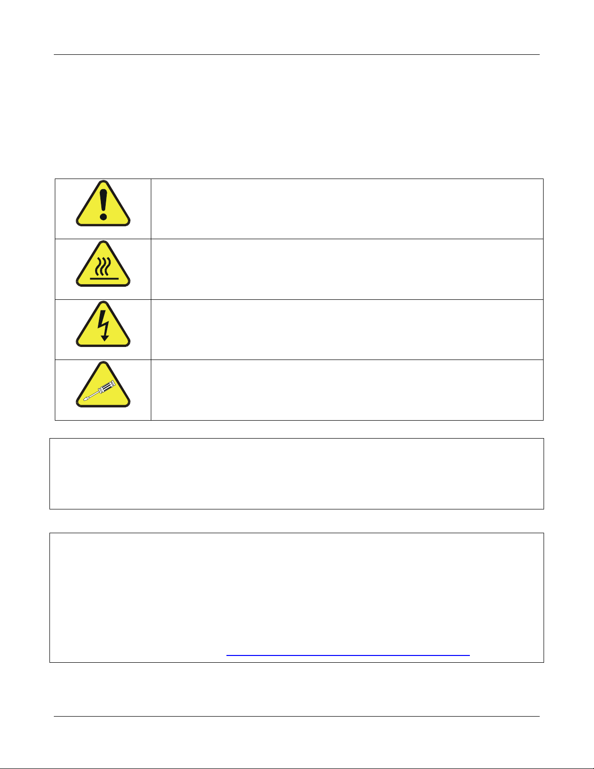
GENERAL SAFETY HAZARD: Refer to the instructions for details on the
specific hazard.
CAUTION: Hot Surface Warning
CAUTION: Electrical Shock Hazard
TECHNICIAN SYMBOL: All operations marked with this symbol are to
be performed by qualified maintenance personnel only.
CAUTION
The monitor should only be used for the purpose and in the manner described in this
manual. If you use the monitor in a manner other than that for which it was intended,
unpredictable behavior could ensue with possible hazardous consequences.
NOTE
Technical Assistance regarding the use and maintenance of the Model 460L Nema Ozone
Monitor or any other Teledyne Instruments product can be obtained by:
Contacting Teledyne Instruments’ Customer Service Department at 800-324-5190
or
Via the internet at http://www.teledyne-api.com/inquiries.asp
05228 Rev B i
DCN 5164 PRINTED DOCUMENTS ARE UNCONTROLLED
Page 4

TELEDYNE INSTRUMENTS
Safety Messages 460L Instruction Manual
THIS PAGE IS INTENTIONALLY LEFT BLANK
ii 05228 Rev B
PRINTED DOCUMENTS ARE UNCONTROLLED DCN 5164
Page 5

TELEDYNE INSTRUMENTS
460L Instruction Manual Table of Contents
TABLE OF CONTENTS
1. INTRODUCTION ........................................................................................................................... 1
1.1. Preface ..................................................................................................................................1
1.2. 460L Documentation................................................................................................................1
1.3. Using This Manual ...................................................................................................................2
2. SPECIFICATIONS AND WARRANTY .............................................................................................. 5
2.1. Specifications .........................................................................................................................5
2.2. Warranty................................................................................................................................6
3. GETTING STARTED....................................................................................................................... 7
3.1. Unpacking ..............................................................................................................................7
3.2. Mechanical Installation .............................................................................................................9
3.3. Pneumatic Connections ..........................................................................................................10
3.4. Electrical Connections ............................................................................................................ 12
3.4.1. AC Power Connection.......................................................................................................12
3.5. Signal I/O Connections........................................................................................................... 13
3.5.1. Analog Output ................................................................................................................13
3.5.2. Digital Status Outputs......................................................................................................14
3.5.3. Control Inputs ................................................................................................................ 15
3.5.4. Relay Outputs.................................................................................................................15
3.6. Initial Startup .......................................................................................................................17
3.7. Setting up the Serial Communications Port................................................................................ 17
3.7.1. Physical Serial Port Configuration ......................................................................................18
3.7.2. Software Setup for Serial Port Communications ...................................................................19
4. FREQUENTLY ASKED QUESTIONS................................................................................................21
5. OPTIONAL HARDWARE AND SOFTWARE .....................................................................................23
5.1. Sample Conditioning System................................................................................................... 23
5.2. Current Loop Analog Output.................................................................................................... 23
5.3. Ozone Destruct Option ...........................................................................................................23
6. OPERATING INSTRUCTIONS .......................................................................................................25
6.1. Front Panel Display................................................................................................................ 25
6.1.1. O
6.1.2. Zero Point Calibration ...................................................................................................... 25
6.1.3. Status LED’s...................................................................................................................25
6.2. Concentration Alarms............................................................................................................. 26
6.2.1.1. Concentration Alarm Configuration.............................................................................. 26
6.2.1.2. Remotely Sensing the Status of the Alarm.................................................................... 26
6.2.1.3. Clearing Alarms........................................................................................................ 26
7. SERIAL COMMUNICATIONS.........................................................................................................27
7.1. Serial Port Command Syntax...................................................................................................27
7.2. Serial Port Command Summary............................................................................................... 28
7.3. Serial Port Command Reference .............................................................................................. 29
7.3.1. ALMACK.........................................................................................................................29
7.3.2. ALMSTAT .......................................................................................................................30
7.3.3. CZERO ..........................................................................................................................31
7.3.4. DACSTEP .......................................................................................................................32
7.3.5. O
7.3.6. SETADDR.......................................................................................................................34
7.3.7. TDUMP ..........................................................................................................................35
7.3.8. TLIST ............................................................................................................................ 36
7.3.9. VGET ............................................................................................................................37
7.3.10. VLIST ..........................................................................................................................38
7.3.11. VSET ........................................................................................................................... 39
8. CALIBRATION .............................................................................................................................41
8.1. Zero Point calibration............................................................................................................. 41
8.2. Span Point Calibration............................................................................................................ 41
8.3. Adjusting the Optional Current Loop Output .............................................................................. 43
9. MAINTENANCE:...........................................................................................................................45
9.1. Replacing the Particulate Filter Element .................................................................................... 45
readout ....................................................................................................................25
3
.................................................................................................................................33
3
05228 Rev B iii
DCN 5164 PRINTED DOCUMENTS ARE UNCONTROLLED
Page 6

TELEDYNE INSTRUMENTS
Table of Contents 460L Instruction Manual
9.1.1. Filter Replacement Procedure............................................................................................45
9.1.2. Mounting the Particulate Filter Externally............................................................................ 46
9.2. Maintaining the Optional H
9.2.1. Draining the Optional Coalescing Filter ...............................................................................47
9.2.2. Replacing the Coalescing Membrane ..................................................................................48
9.3. UV Lamp Replacement ........................................................................................................... 49
9.4. Cleaning Exterior Surfaces of the 460L ..................................................................................... 50
9.5. Degree of Protection ..............................................................................................................50
10. THEORY OF OPERATION............................................................................................................51
10.1. Basic O
Measurement Principle .............................................................................................51
3
10.1.1. (Beer’s Law)................................................................................................................. 51
10.1.2. The Absorption Path ...................................................................................................... 52
10.1.3. The Reference / Measurement Cycle ................................................................................53
10.1.4. Digital Noise Filter ......................................................................................................... 54
10.2. Pneumatic Theory of Operation.............................................................................................. 55
10.2.1. Basic Pneumatic Flow And Flow Control ............................................................................55
10.2.2. Internal Pump and Flow Control.......................................................................................55
10.2.3. Optional Sample Conditioning .........................................................................................56
10.2.3.1. H
10.2.3.2. H
O Coalescing Filter ............................................................................................... 56
2
O Vapor Dryer..................................................................................................... 56
2
10.2.3.3. Ozone Destruct Scrubber ......................................................................................... 57
10.3. Electronic Theory of Operation............................................................................................... 58
10.3.1. Main Board................................................................................................................... 58
10.3.2. O
10.3.2.1. O
Sensor Module.......................................................................................................... 59
3
Sensor Components ............................................................................................ 59
3
10.3.2.2. Sensor Module PCA .................................................................................................60
10.3.3. CPU Board....................................................................................................................61
10.3.3.1. I/O Functions ......................................................................................................... 61
10.3.3.2. Status and Alarm Functions...................................................................................... 61
10.3.4. Display Driver and Keyboard Assembly............................................................................. 62
10.3.4.1. Keyboard............................................................................................................... 62
10.3.4.2. Display.................................................................................................................. 62
10.3.4.3. Display Driver ........................................................................................................62
10.3.5. Power Distribution ......................................................................................................... 63
11. TROUBLESHOOTING..................................................................................................................65
11.1. Status Output Summary .......................................................................................................65
11.2. Troubleshooting Using Status Outputs .................................................................................... 65
11.2.1. Sensor OK.................................................................................................................... 65
11.2.2. Invalid Reading............................................................................................................. 66
11.2.3. Lamp Low .................................................................................................................... 66
11.2.4. Status LED / Status Output Troubleshooting Summary .......................................................66
11.3. Concentration Alarm Outputs.................................................................................................67
11.4. Technical Assistance ............................................................................................................68
12. A PRIMER ON ELECTRO-STATIC DISCHARGE.............................................................................69
12.1. How Static Charges are Created.............................................................................................69
12.2. How Electro-Static Charges Cause Damage .............................................................................70
12.3. Common Myths About ESD Damage ....................................................................................... 71
12.4. Basic Principles of Static Control ............................................................................................ 72
12.4.1. General Rules ...............................................................................................................72
12.4.2. Basic anti-ESD Procedures for Analyzer Repair and Maintenance ..........................................73
12.4.2.1. Working at the Instrument Rack................................................................................73
12.4.2.2. Working at an Anti-ESD Work Bench.......................................................................... 73
12.4.2.3. Transferring Components from Rack to Bench and Back................................................74
12.4.2.4. Opening Shipments from Teledyne Instruments’ Customer Service.................................75
12.4.2.5. Packing Components for Return to Teledyne Instruments Customer Service ...................76
O Coalescing Filter ........................................................................... 47
2
iv 05228 Rev B
PRINTED DOCUMENTS ARE UNCONTROLLED DCN 5164
Page 7

TELEDYNE INSTRUMENTS
460L Instruction Manual Table of Contents
List of Figures
Figure 3-1 M460L Front Cover Layout .............................................................................7
Figure 3-2 460L Layout ................................................................................................8
Figure 3-3 460L Sensor Module Layout ........................................................................... 9
Figure 3-4 460L Mounting Hole Locations and Dimensions ............................................... 10
Figure 3-5 460L Pneumatic Connections........................................................................ 11
Figure 3-6 Location of Electrical Connectors................................................................... 12
Figure 3-7 Signal I/O Connector Pin Assignments........................................................... 13
Figure 3-8 Digital Status Output Connections................................................................. 14
Figure 3-9 Control Input Connections ........................................................................... 15
Figure 3-10 Alarm Output Relays................................................................................... 16
Figure 3-11 RS-232/RS-485 Jumper Location and Settings................................................ 18
Figure 3-12 Typical RS-232 and RS-485 Connections........................................................ 19
Figure 8-1 Setup for Measuring Current Output Signal Level ............................................ 43
Figure 8-2 Location Current Output Adjustment Potentiometers ....................................... 44
Figure 9-1 Changing the Particulate Filter...................................................................... 45
Figure 9-2 Changing the Particulate Filter...................................................................... 46
Figure 9-3 Draining the Optional H2O Coalescing filter..................................................... 47
Figure 9-4 Replacing the Membrane of the Optional H2O Coalescing filter........................... 48
Figure 9-5 UV Lamp Set Screws and Calibration Test Points............................................. 49
Figure 10-1 O3 Absorption Path ..................................................................................... 53
Figure 10-2 Reference / Measurement Gas Cycle ............................................................. 53
Figure 10-3 460L Internal Pneumatic Diagram – Basic Configuration................................... 55
Figure 10-4 460L Internal Pneumatic Diagram with Optional Sample Conditioning ................ 56
Figure 10-5 460L Electronic Block Diagram ..................................................................... 58
Figure 10-6 460L Power Distribution Block Diagram ......................................................... 63
Figure 12-1 Triboelectric Charging ................................................................................. 69
Figure 12-2 Basic anti-ESD Workbench........................................................................... 72
LIST OF TABLES
Table 2-1 460L Specifications....................................................................................... 5
Table 3-1 460L Ventilation Clearances ......................................................................... 10
Table 3-2 Digital Status Output Descriptions................................................................. 14
Table 3-3 Control Inputs............................................................................................ 15
Table 3-4 Relay Output Operation............................................................................... 16
Table 3-5 Serial I/O Port Connection ........................................................................... 17
Table 3-6 Serial Port Configuration.............................................................................. 20
Table 6-1 Status LED’s .............................................................................................. 25
Table 6-2 Concentration Alarm Default Settings ............................................................ 26
Table 7-1 Serial Port Command Summary.................................................................... 28
Table 7-2 VAR_INDEX List for VGET Command ............................................................. 37
Table 7-3 VAR_INDEX List for VSET Command.............................................................. 39
Table 10-1 Measurement / Reference Cycle.................................................................... 54
Table 11-1 Digital Status Outputs Definitions ................................................................. 65
Table 11-2 Status LED / Output Trouble shooting Truth Table........................................... 67
Table 11-3 Alarm Output Troubleshooting...................................................................... 67
Table 12-1 Static Generation Voltages for Typical Activities .............................................. 70
Table 12-2 Sensitivity of Electronic Devices to Damage by ESD......................................... 70
05228 Rev B v
DCN 5164 PRINTED DOCUMENTS ARE UNCONTROLLED
Page 8

TELEDYNE INSTRUMENTS
Table of Contents 460L Instruction Manual
LIST OF APPENDICES
Appendix A – Spare Parts List
Appendix B – List of Schematics
vi 05228 Rev B
PRINTED DOCUMENTS ARE UNCONTROLLED DCN 5164
Page 9

TELEDYNE INSTRUMENTS
460L Instruction Manual Introduction
1. INTRODUCTION
1.1. Preface
Teledyne Instruments is pleased that you have purchased the Model 460L NEMA Ozone Monitor.
Included is a full one-year warranty (see Section 2.2) and we at Teledyne Instruments will be
pleased to provide you with any support required so that you may utilize our equipment to the
fullest extent.
The Model 460L is a microprocessor based low range ozone monitor for safety monitoring of ozone
levels in a variety of applications such as water treatment, food processing, and research. The
design has been specifically optimized for applications requiring the measurement of ozone at the
typically low concentration levels encountered when tracking ambient conditions. The Model 460L
has been designed to give accurate and stable readings over long time periods with little or no
maintenance or calibration.
The flexibility of the software as well as the analog and digital I/O allow the Model 460L to
interface with a broad range of devices for process control and data logging.
We hope you will not experience any problems with the Teledyne Instruments Model 460L but if
you do, our full time customer service department is always available to answer your questions.
1.2. 460L Documentation
The documentation for this monitor is available in several different formats:
Printed format, part number 050120100
Electronic format on a CD-ROM, part number 050120200
The electronic manual is in Adobe
Acrobat Reader
the Internet at http://www.adobe.com/.
The electronic version of the manual has many
Keyword and phrase search feature
Figures, tables and internet addresses are linked so that clicking on the item will display
the associated feature or open the website.
®
software, which is necessary to view these files, can be downloaded for free from
®
Systems Inc. “Portable Document Format”. The Adobe®
advantages:
A list of chapters and sections as well as thumbnails of each page are displayed to the left
of the text.
Entries in the table of contents are linked to the corresponding locations in the manual.
Ability to print sections (or all) of the manual
05228 Rev B 1
DCN 5164 PRINTED DOCUMENTS ARE UNCONTROLLED
Page 10

TELEDYNE INSTRUMENTS
Introduction 460L Instruction Manual
1.3. Using This Manual
This manual has the following data structures:
1.0 Table of Contents:
Outlines the contents of the manual in the order the information is presented. This is a good
overview of the topics covered in the manual. There is also a list of tables, a list of figures and a
list of appendices. In the electronic version of the manual, clicking on any of these table entries
automatically views that section.
2.0 Specifications and Warranty
This section contains a list of the monitor’s performance specifications, a description of the
conditions and configuration under which Teledyne Instruments Incorporated warranty statement
applies.
3.0 Getting Started:
A concise set of instructions for setting up, installing and starting your monitor for the first time.
This includes unpacking; mechanical installation; attaching all pneumatic lines; attaching all
electrical and electronic connections and the physical configuration the RS-232/RS-485 port.
4.0 FAQ:
Answers to the most frequently asked questions about operating the monitor.
5.0 Optional Hardware & Software
A description of optional equipment to add functionality to your monitor.
6.0 Operation Instructions
Instructions for operating the monitor and using its basic features and functions.
7.0 Serial Communications
Information regarding the syntax and command definitions for the monitor’s serial I/O interface.
8.0 Calibration Procedures
General information and step-by-step instructions for manually calibrating your monitor.
9.0 Monitor Maintenance
Description of certain preventative maintenance procedures that should be regularly performed on
your monitor to keep it in good operating condition.
10.0 Theory of Operation
An in-depth look at the various principals by which your monitor operates as well as a description
of how the various electronic, mechanical and pneumatic components of the monitor work and
2 05228 Rev B
PRINTED DOCUMENTS ARE UNCONTROLLED DCN 5164
Page 11

TELEDYNE INSTRUMENTS
460L Instruction Manual Introduction
interact with each other. A close reading of this section is invaluable for understanding the
monitor’s operation.
11.0 Troubleshooting Section:
This section includes pointers and instructions for diagnosing problems with the monitor, such as
excessive noise or drift, as well as instructions on performing repairs of the monitor’s major
subsystems.
12.0 Electro-Static Discharge (ESD) Primer:
This section describes how static electricity occurs; why it is a significant concern and how to
avoid it and; how to avoid allowing ESD to affect the reliable and accurate operation of your
monitor.
USER NOTES:
05228 Rev B 3
DCN 5164 PRINTED DOCUMENTS ARE UNCONTROLLED
Page 12

TELEDYNE INSTRUMENTS
Introduction 460L Instruction Manual
USER NOTES:
4 05228 Rev B
PRINTED DOCUMENTS ARE UNCONTROLLED DCN 5164
Page 13

TELEDYNE INSTRUMENTS
460L Instruction Manual Specifications and Warranty
2. SPECIFICATIONS AND WARRANTY
2.1. Specifications
Table 2-1 460L Specifications
Measurement Principle UV Absorption (Beer Lambert Law)
Ranges 1ppm to 500 ppm: User selectable
Measurement Units ppm; ppb
Accuracy 1% of Full Scale
Zero Noise < 0.0015 ppm (rms)
Span Noise < 0.5% of reading (rms) (above 0.1 ppm)
Lower Detectable Limit < 0.003 ppm (rms)
Linearity Better than 1% of selected range
Response Time (95%) <30 sec
Repeatability 0.5% of selected range
Display Resolution 0001 ppm, 1 ppb
Gas Flow Rate 1.0-2.0 LPM
Compensation Pressure, Temperature (NTP = 273.15K, 760mmHg)
Gas Inlet Pressure Range 11.0 – 16.0 psia
Temperature Range 5-45 ˚C
Humidity Range 10-90% RH, Non-Condensing
Dimensions (H x W x D) 12.64" x 11.19" x 6.08"
(321mm x 284mm x 154mm)
Weight 9.40lb (4.27kg)
Power 110-240V~, 50/60Hz, 200 VA
Environmental Conditions Installation Category (Over Voltage Category) II
Pollution Degree 2
Maximum Operating Altitude 2000 meters
Analog Voltage Output Single output: 0-5V,
Option available converting voltage output to 4-20mA output
with maximum voltage between outputs and ground 60V peak
Relay Outputs 3 relay outputs: Sensor OK and two concentration alarms (HI &
Hi-Hi)
Relay type & Output Rating SPDT: 250V AC, 3A
Degree of Protection (IP Code) IP65 (NEMA 4X)
05228 Rev B 5
DCN 5164 PRINTED DOCUMENTS ARE UNCONTROLLED
Page 14

TELEDYNE INSTRUMENTS
Specifications and Warranty 460L Instruction Manual
2.2. Warranty
WARRANTY POLICY (02024D)
Prior to shipment, T-API equipment is thoroughly inspected and tested. Should equipment failure
occur, T-API assures its customers that prompt service and support will be available.
COVERAGE
After the warranty period and throughout the equipment lifetime, T-API stands ready to provide
on-site or in-plant service at reasonable rates similar to those of other manufacturers in the
industry. All maintenance and the first level of field troubleshooting is to be performed by the
customer.
NON-API MANUFACTURED EQUIPMENT
Equipment provided but not manufactured by T-API is warranted and will be repaired to the
extent and according to the current terms and conditions of the respective equipment
manufacturers warranty.
GENERAL
During the warranty period, T-API warrants each Product manufactured by T-API to be free from
defects in material and workmanship under normal use and service. Expendable parts are
excluded.
If a Product fails to conform to its specifications within the warranty period, API shall correct such
defect by, in API's discretion, repairing or replacing such defective Product or refunding the
purchase price of such Product.
The warranties set forth in this section shall be of no force or effect with respect to any Product:
(i) that has been altered or subjected to misuse, negligence or accident, or (ii) that has been used
in any manner other than in accordance with the instruction provided by T-API, or (iii) not
properly maintained.
THE WARRANTIES SET FORTH IN THIS SECTION AND THE REMEDIES THEREFORE ARE
EXCLUSIVE AND IN LIEU OF ANY IMPLIED WARRANTIES OF MERCHANTABILITY, FITNESS FOR
PARTICULAR PURPOSE OR OTHER WARRANTY OF QUALITY, WHETHER EXPRESSED OR IMPLIED.
THE REMEDIES SET FORTH IN THIS SECTION ARE THE EXCLUSIVE REMEDIES FOR BREACH OF
ANY WARRANTY CONTAINED HEREIN. API SHALL NOT BE LIABLE FOR ANY INCIDENTAL OR
CONSEQUENTIAL DAMAGES ARISING OUT OF OR RELATED TO THIS AGREEMENT OF T-API'S
PERFORMANCE HEREUNDER, WHETHER FOR BREACH OF WARRANTY OR OTHERWISE
6 05228 Rev B
PRINTED DOCUMENTS ARE UNCONTROLLED DCN 5164
Page 15
TELEDYNE INSTRUMENTS
460L Instruction Manual Getting Started
3. GETTING STARTED
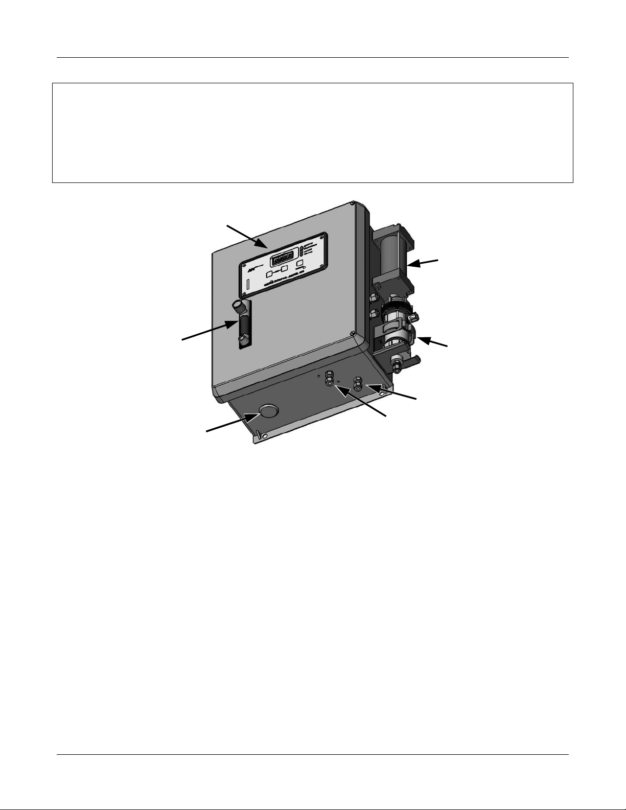
3.1. Unpacking
1. Inspect the received packages for external shipping damage. If damaged, please advise
the shipper first, then Teledyne Instruments.
2. Loosen the 2 setscrews located in the top and bottom left corners of the front and swing
open the cover.
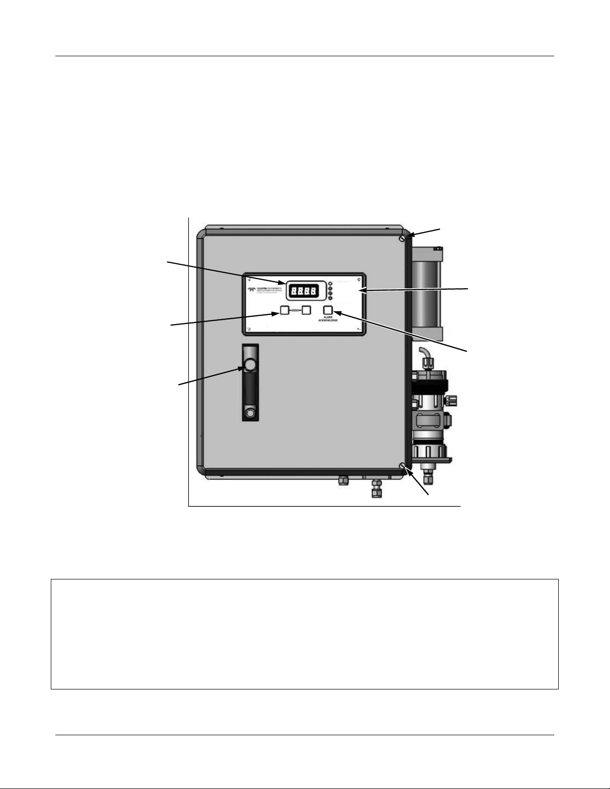
O3 Concentration
Display
SYSTEM OK
INVALID READING
LAMP LOW
ALARM ACTIVE
Set Screw
Status
LED’s
ZERO
Buttons
Gas
Ozone Monitor – Model 460L
Alarm
Acknowledge
Key
Flowmeter
&
Control
Set Screw
Figure 3-1 M460L Front Cover Layout
3. Inspect the interior of the monitor to make sure all circuit boards and other components
are in good shape and properly seated.
NOTE
Printed circuit assemblies (PCAs) are static sensitive. Electro-static discharges (ESD),
too small to be felt by the human nervous system, are large enough to destroy sensitive
circuits.
Before touching PCAs, read Chapter 12 of this manual and follow the procedure
described there for avoiding damage to your monitor due to ESD.
05228 Rev B 7
DCN 5164 PRINTED DOCUMENTS ARE UNCONTROLLED
Page 16
TELEDYNE INSTRUMENTS
Getting Started 460L Instruction Manual
CAUTION
Never disconnect electronic circuit boards, wiring harnesses or
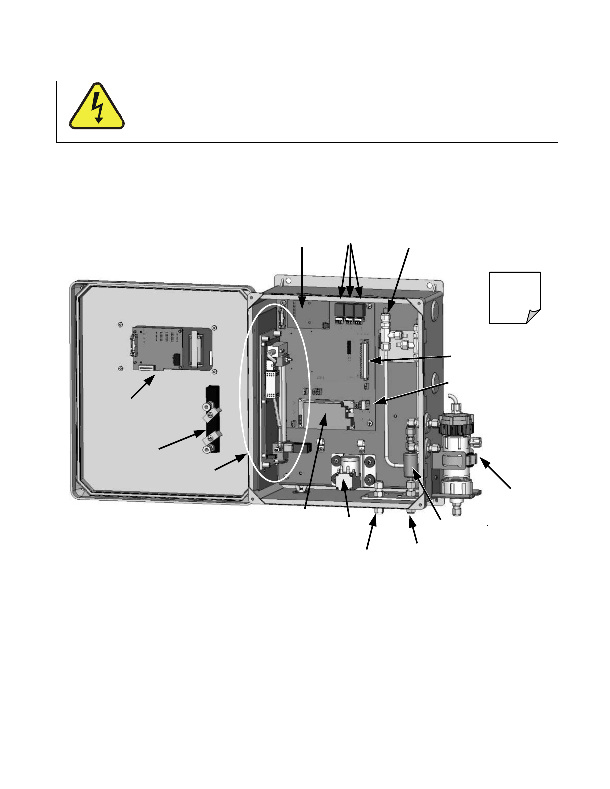
4. Check the connectors of the various internal wiring harnesses and pneumatic hoses to
make sure they are firmly and properly seated (see Figure 3-2).
5. Verify that all of the optional hardware ordered with the unit has been installed. These are
listed on the paperwork accompanying the monitor.
electronic subassemblies while the unit is under power.
Analog Relay
CPU
Board
Outputs
O Vapor Dryer
H
2
(optional)
Scrubber
Not Shown
Optional
Ozone
Display
Board
Flow Meter
Sensor Module
Main
Board
Main
Power
Supply
Pump
Exhaust
Outlet
Figure 3-2 460L Layout
Particulate
Filter
Ozone
Inlet
Signal I/O
Connector
AC Power
Input
Connector
H2O
Coalescing
Filter
(optional)
8 05228 Rev B
PRINTED DOCUMENTS ARE UNCONTROLLED DCN 5164
Page 17
TELEDYNE INSTRUMENTS
A
460L Instruction Manual Getting Started
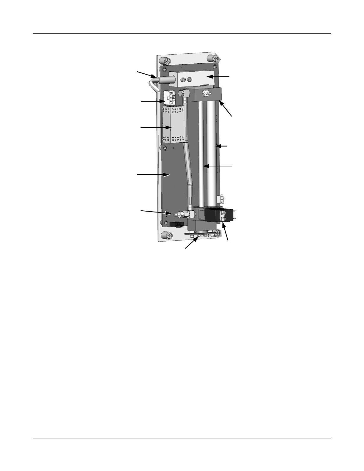
UV
Lamp
UV Lamp
Power Connector
UV Lamp
Power Supply
Sensor
Module PCA
UV Lamp
Housing
Ozone Outlet
Manifold
Reference
Scrubber
bsorption
Tube
Ozone Intlet
Manifold
UV
Detector
Measure / Reference
Valve
Figure 3-3 460L Sensor Module Layout
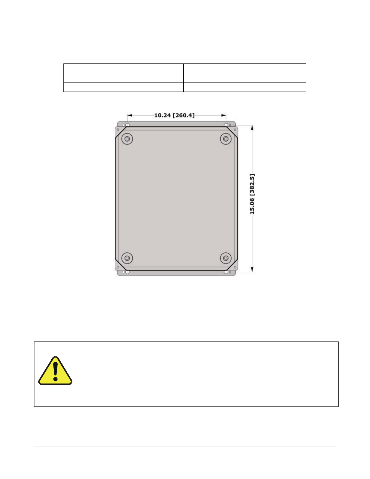
3.2. Mechanical Installation
Mount the enclosure securely to a vertical surface.
Figure 3-4 below shows the locations of the four mounting holes.
All four mounting holes should be used to secure the monitor.
Use stainless steel, 5/16” diameter bolts.
VENTILATION CLEARANCE:
When installing the monitor be sure to leave sufficient ventilation clearance.
05228 Rev B 9
DCN 5164 PRINTED DOCUMENTS ARE UNCONTROLLED
Page 18
TELEDYNE INSTRUMENTS
Getting Started 460L Instruction Manual
Table 3-1 460L Ventilation Clearances
AREA MINIMUM REQUIRED CLEARANCE
Sides of the monitor 1 inch
Above and below the monitor. 1 inch
Figure 3-4 460L Mounting Hole Locations and Dimensions
3.3. Pneumatic Connections
1. Connect a ¼” exhaust line to the fitting labeled ‘Exhaust.’
CAUTION
If using the 460L to measure O3 levels that are ≥100 ppb exhaust gas
from the MODEL 460L may contain dangerous levels of ozone!
2. Connect the ozone delivery line to the ¼” inlet fitting labeled “Ozone Inlet” on the bottom
face of the enclosure (See Figure 3-5.)
10 05228 Rev B
PRINTED DOCUMENTS ARE UNCONTROLLED DCN 5164
The optional ozone destruct (see Section 5.3) should be installed
and
Make sure that the exhaust line is vented to an outside area.
Page 19
TELEDYNE INSTRUMENTS
460L Instruction Manual Getting Started
NOTE
The ozone delivery pressure should be at ambient pressure +/- 5 PSIG.
All tubing used should be made of ozone resistant material such as Stainless Steel, PTFE
(Teflon) or FEP. API can supply appropriate tubing for connecting the ozone supply
line.
Display
Ozone
Scrubber
(optional)
Gas
Flowmeter
&
Control
Coalescence
Filter
(optional)
OZONE INLET
Install AC
Power Cord
Through Here
EXHAUST
OUTLET
Figure 3-5 460L Pneumatic Connections
The gas flow rate through the monitor should be established between 1.0 and 2.0 L/min.
05228 Rev B 11
DCN 5164 PRINTED DOCUMENTS ARE UNCONTROLLED
Page 20
TELEDYNE INSTRUMENTS
Getting Started 460L Instruction Manual
3.4. Electrical Connections
NOTE
It is recommended that if multi-strand wires are used for the following electrical
connections. To ensure a reliable connection the wires should be:
“Tinned” with solder or;
Terminated with insulated crimped ferrules, such as Entrelec
(18 gauge) or 304.558.10 (22 gauge)
3.4.1. AC Power Connection
CAUTION
Disconnect power to the AC mains before making or removing any
electrical connections to the 460L.
®
P/N 304.456.02
CAUTION
A proper earth ground connection must be made to the receptacle
labeled “Earth Ground” on the 3-pin AC connector. Failure to do so may
result in a shock hazard and malfunction of the monitor
Connect AC power to the monitor.
3. Install a ½” conduit fitting for routing the electrical wiring into the monitor through the
hole provided (see Figure 3-5). In order to maintain the IP (NEMA4X) rating of the
enclosure, an appropriate sealed conduit connector should be used.
4. Attach the leads of the power line to the AC power connector (see Figure 3-6)
Analog and
Digital I/O
Connector
Relay
Outputs &
Connectors
Ground
AC Line
AC Neutral
AC POWER
Connector
Figure 3-6 Location of Electrical Connectors
12 05228 Rev B
PRINTED DOCUMENTS ARE UNCONTROLLED DCN 5164
Page 21
TELEDYNE INSTRUMENTS
460L Instruction Manual Getting Started
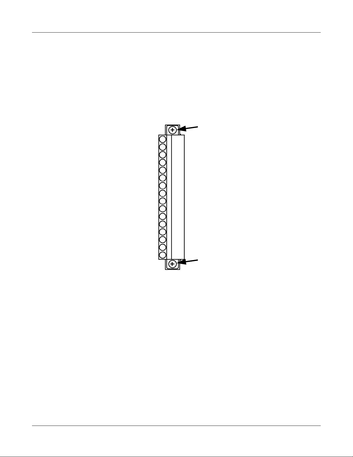
3.5. Signal I/O Connections
All digital and analog signal I/O connections are made via a 16-pin connector on the main board
(See Figure 3-6 for the location of the connector.)
This connector can be unplugged from the header on the main board for easier access when
wiring. To disconnect from main board, loosen the two retaining screws at either end of the
connector.
Retaining Screw
Analog Out +
Analog Out -
Zero Input
Aux Input
Gnd
Status Out 1
Status Out 2
Status Out 3
Status Out 4
Status Com
Serial TX
Serial RX
Serial GND
Status Out 5
Status Out 6
Retaining Screw
Figure 3-7 Signal I/O Connector Pin Assignments
3.5.1. Analog Output
The 460L is equipped with one analog output that is factory configurable as either a 0-5 VDC
signal or a 4-20 mA signal. You may verify how your 460L is set up by checking the information
on the
The analog output requires two connections: ANALOG +, the signal line, and ANALOG–, the
ground connection. See Figure 3-7 for the locations of the ANALOG OUT + and ANALOG OUT–
pins.
monitor’s serial number tag.
05228 Rev B 13
DCN 5164 PRINTED DOCUMENTS ARE UNCONTROLLED
Page 22
TELEDYNE INSTRUMENTS
Getting Started 460L Instruction Manual
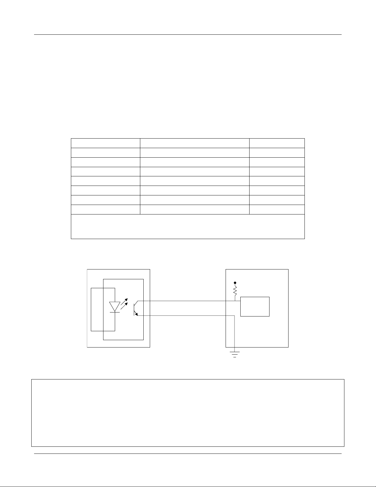
3.5.2. Digital Status Outputs
The 460L has six assigned digital status outputs for indicating error and operational status
conditions of the monitor as well as the status of its O
These outputs are in the form of opto-isolated open-collector transistors. They can be used to
drive status LED’s on a display panel or interface to a digital device such as a Programmable Logic
Controller (PLC). Several of the status outputs are useful tools for diagnosing sensor and system
level malfunctions (see Section 11.2 for more information).
Table 3-2 Digital Status Output Descriptions
concentration alarms (see Table 3-2).
3
LABEL
STATUS OUT 1
STATUS OUT 2
STATUS OUT 3
1
2
2
2
NAME OPERATION
Sensor O.K. Normally On
Invalid Reading Normally Off
Lamp Low Normally Off
STATUS OUT 4 Alarm Active Normally Off
STATUS OUT 5 HI Alarm Status Normally Off
STATUS OUT 6 HI-HI Alarm Status Normally Off
STATUS COM Common Pin for all Status Outputs N/A
1
See Figure 3-7 for pin locations of the these output lines on the monitor’s 16-pin I/O
connector
2
See Section 11-2 for definitions and interpretations of these output.
Figure 3-8 shows the most common way of connecting the digital outputs to an external device
such as PLC.
460M
Status Outputs 1-6 (C ollector)
STATUS COM (Emitter)
PLC OR OTHER DEVICE
+5V
Digital Input
Opto-Isolator
Ground
Connection
Provided by PLC
Figure 3-8 Digital Status Output Connections
Note
Most devices, such as PLC’s, have internal provision for limiting the current that the
input will draw from an external device.
When connecting to a unit that does not have this feature, external dropping-resistors
must be used to limit the current through the transistor output to 50mA or less.
At 50 mA, the transistor will drop approximately 0.2V from its collector to emitter.
14 05228 Rev B
PRINTED DOCUMENTS ARE UNCONTROLLED DCN 5164
Page 23
TELEDYNE INSTRUMENTS
g
460L Instruction Manual Getting Started
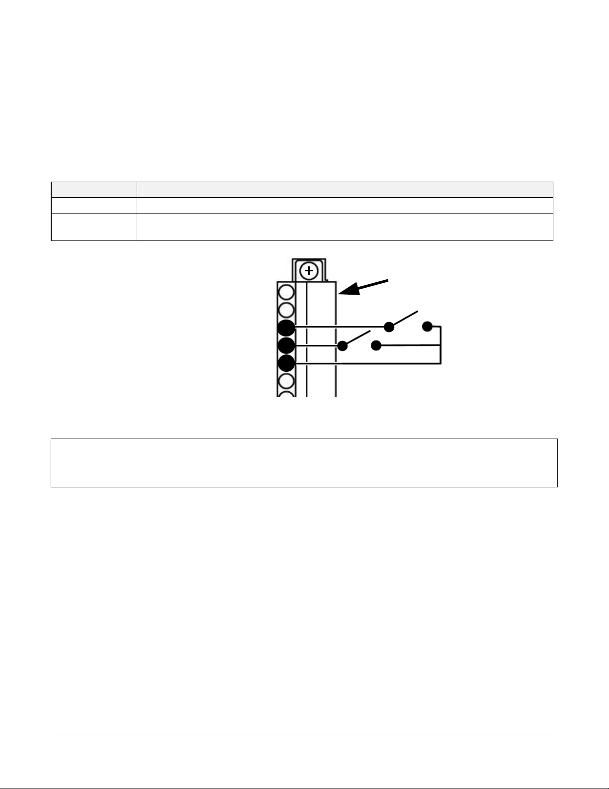
3.5.3. Control Inputs
Two digital control inputs are also available for use on the 460L. The control inputs are used for
remote control of the 460L by a device such as a PLC. They are labeled ZERO INPUT and AUX
INPUT (see Figure 3-9).
Table 3-
INPUT DESCRIPTION
ZERO INPUT This input performs exactly the same function as the ‘Zero’ buttons on the front panel.
AUX INPUT This input can be used to clear active concentration alarms in similar fashion as the serial
communications ALMACK.
3 Contro
l Inputs
Signal I/O
Connector
Analog Out +
Analo
Out -
Zero Input
Aux Input (AlmAck)
Gnd
Figure 3-9 Control Input Connections
NOTE:
Never connect a voltage level output from another device to these contacts.
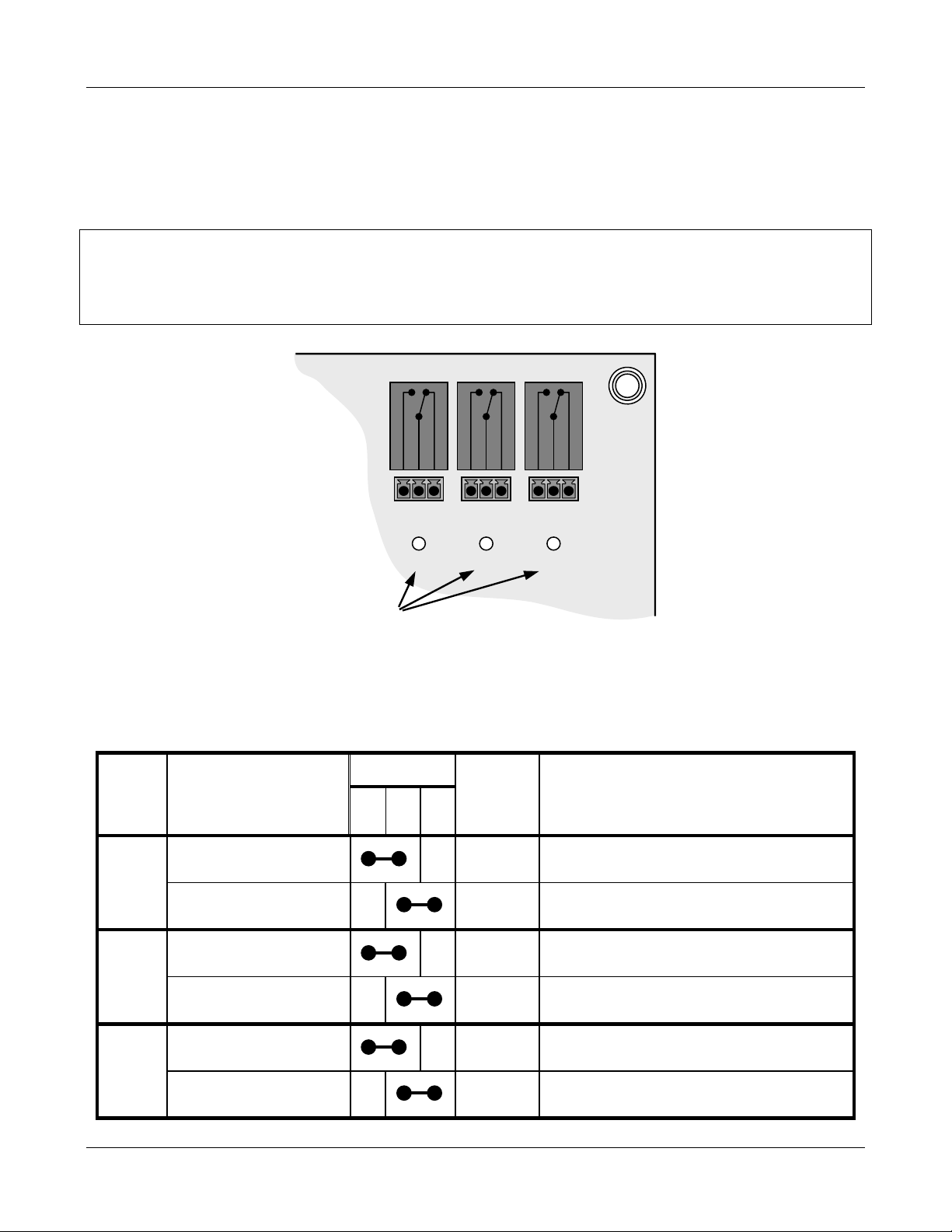
3.5.4. Relay Outputs
The 460L is equipped with three SPDT relays. They are located at the top right hand side of the
main board and are labeled RELAY 1, RELAY 2 & RELAY 3.
RELAY 1 corresponds to the Sensor OK status output and LED;
RELAY 2 corresponds to the HI concentration alarm, and;
RELAY 3 corresponds to the HI-HI concentration alarm
See Section 11.2.1 for more information on the Sensor OK status output.
See Section 6.2 for more information on these alarms.
05228 Rev B 15
DCN 5164 PRINTED DOCUMENTS ARE UNCONTROLLED
Page 24
TELEDYNE INSTRUMENTS
Getting Started 460L Instruction Manual
Below each relay is a 3-pin connector that allows the relay to be connected for either
normally open or normally closed operation.
Table 3-4 describes how to connect the alarm relays.
NOTE
The relay contacts are rated to 3A at 240VAC. Do not exceed these ratings when
connecting equipment to the instrument.
RELAY FUNCTION
STATUS LEDS
RELAY 1
N.O.
COM
D6
RELAY 2
N.C.
N.O.
D7
RELAY 3
N.C.
COM
N.O.
Figure 3-10 Alarm Output Relays
Table 3-4 Relay Output Operation
RELAY PIN
N.
O.
STATE
C
O
M
2
N.
C.
STATUS
1
LED
N.C.
COM
D8
COMMENTS
SENSOR OK ON
D6 ON 460L is operating normally
1
SENSOR OK OFF
HI Alarm ON
D6 OFF
D7 ON O3 concentration > HI alarm limit
Problem with the O
See Section 11.2.
sensor module.
3
2
HI Alarm OFF
HI-HI Alarm ON
D7 OFF O3 concentration < HI alarm limit
D8 ON O3 concentration > HI-HI alarm limit
3
HI-HI Alarm OFF
16 05228 Rev B
PRINTED DOCUMENTS ARE UNCONTROLLED DCN 5164
D8 OFF O3 concentration < HI-HI alarm limit
Page 25

TELEDYNE INSTRUMENTS
460L Instruction Manual Getting Started
1
Located just below each relay connector (see Figure 3-10)
2
N.O. = Normally Open operation.
N.C. = Normally Closed operation.
3.6. Initial Startup
Perform the following steps when initially starting up the 460L or when bringing the monitor back
into service it has been shut down for repair or maintenance.
1. Turn on power to the monitor.
The display will briefly display the “API” logo followed by the software version.
The display will then begin showing ozone concentration.
2. Establish a flow of ozone to the monitor.
Flow rate through the monitor should be between 0.5 – 2.0 LPM (Liters per minute.)
Adjust as needed using the needle valve of the flow meter on the front panel
(see Figure 3-1).
3. Let the monitor warm up for a minimum of 5 minutes.
4. Check Status LED’s on front panel;
Sensor OK LED should be ON.
All other LED’s should be OFF.
If the Status LED’s are not in this state, refer to Chapter 11 for troubleshooting
information.
5. Observe the monitor for several more minutes at zero to ensure that it is stable.
THE MONITOR IS NOW READY TO MEASURE OZONE.
3.7. Setting up the Serial Communications Port
The 460L’s bi-directional RS-232/485 Serial Port Interface allows the user to communicate with
the monitor via a computer over that computer’s serial communications port (COM port). A
terminal emulation program such as HyperTerminal is required to be installed and running on the
host computer.
The following three pins are provided on the I/O connector for serial communications (see Figure
3-12).
Table 3-
LABEL DESCRIPTION
SERIAL TX Serial Transmit (RS-485 – A)
SERIAL RX Serial Receive (RS-485 – B)
SERIAL GND Serial Ground (RS-232 Only)
5 Serial I/O Port C
onnection
05228 Rev B 17
DCN 5164 PRINTED DOCUMENTS ARE UNCONTROLLED
Page 26
TELEDYNE INSTRUMENTS
Getting Started 460L Instruction Manual
While the standard factory configuration is for RS-232, the monitor’s serial port can be configured
for either RS-232 or RS-485 (see Section 3.7.1 for the procedure).
Use RS-232 for direct connection to a nearby (no more than 6-8 feet cable length) PC or
Laptop, RS-232 should be used.
Use RS-485 for permanent connection to continuously operating data acquisition systems
or connections over greater distances.
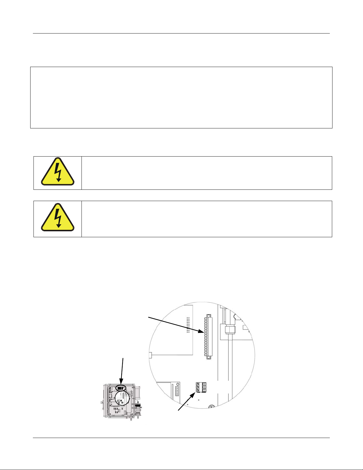
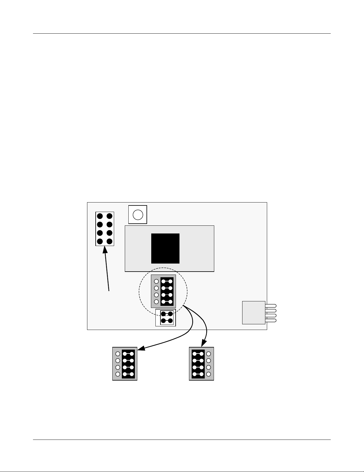
3.7.1. Physical Serial Port Configuration
6. To configure the com port for RS-232 or RS-485, move the 4 shunts on JP3 of the CPU PCA
(P/N #03492) to the proper position as shown in below.
The jumpers may already be in this position but this still needs to be verified.
Also make sure that JP1 is jumpered. It may be hanging off of one pin, make sure it is
jumpered together as in Figure 3-11.
JP2 can either be jumpered or not as it is already shorted on the board.
Reset Button
Micro-Controller
Connector for
Optional 4-20 mA
output
JP2
JP1
JP3
JP3 set for RS-232 JP3 set for RS-485
Figure 3-11 RS-232/RS-485 Jumper Location and Settings
18 05228 Rev B
PRINTED DOCUMENTS ARE UNCONTROLLED DCN 5164
Page 27
TELEDYNE INSTRUMENTS
A
460L Instruction Manual Getting Started
7. Connect the appropriate type of cable to the 16 pin Signal I/O connector inside the
analyzer.
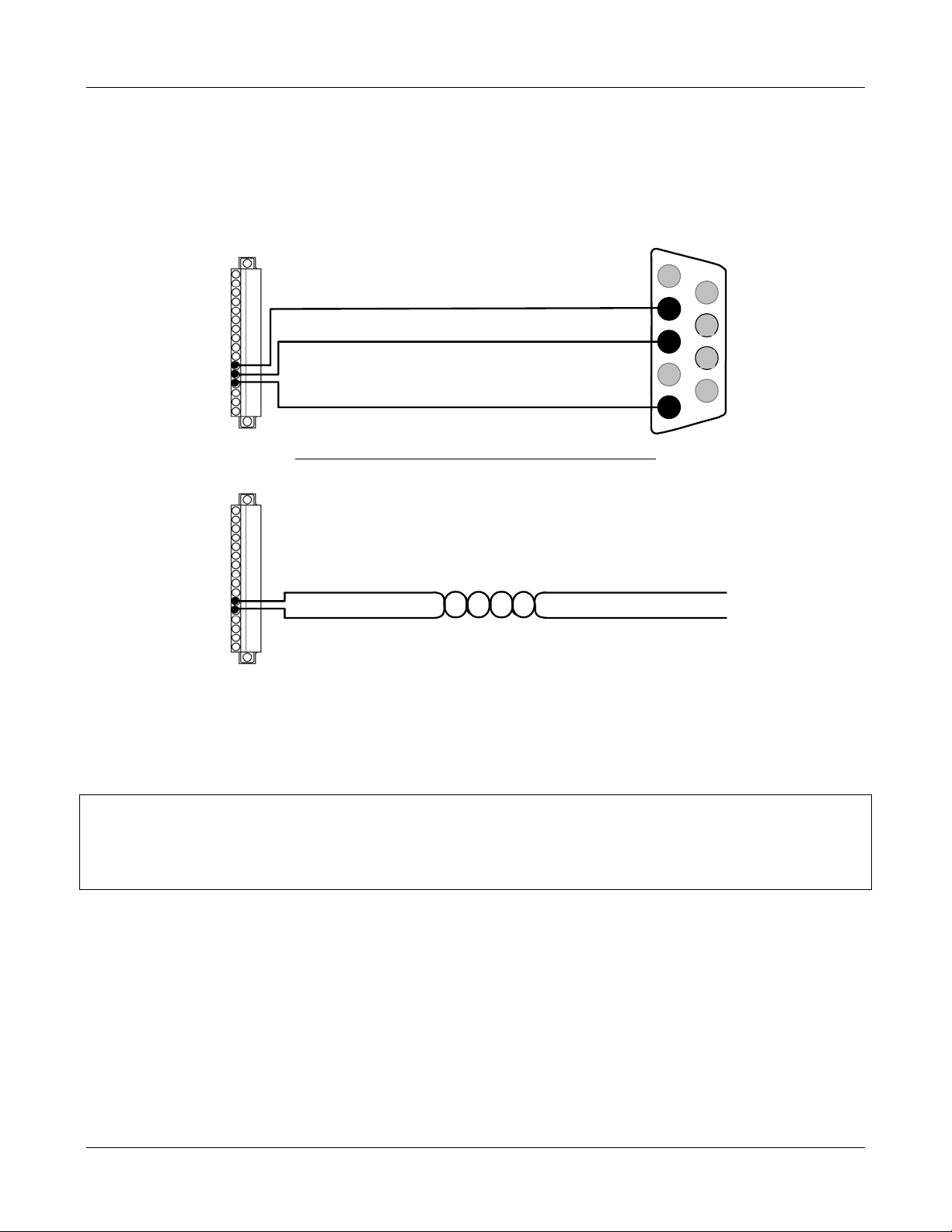
8. A cable may be included with you instrument. If not, Figure 3-12 below illustrates how to
construct wiring for both RS-232 and RS-485
RS-232
Serial TXD
Serial RXD
Serial GND
connections.
DB9 Female
1
6
2
7
3
8
4
9
5
RS-485
Serial TXD
Serial RXD
Twisted Pair
RS-485-
RS-485-B
Figure 3-12 Typical RS-232 and RS-485 Connections
3.7.2. Software Setup for Serial Port Communications
NOTE
This section refers to various serial communication commands for the M460M. For
detailed information regarding these commands see Chapter 7.
1. Connect the other end of the cable to your serial Com port on your computer
2. Open up Hyper-terminal or another terminal program and set up a connection with the
settings below. Your com port is most likely COM1.
05228 Rev B 19
DCN 5164 PRINTED DOCUMENTS ARE UNCONTROLLED
Page 28

TELEDYNE INSTRUMENTS
Getting Started 460L Instruction Manual
The Serial Port of the device being used to communicate with the 460L should be
configured as follows:
Table 3-6 Serial Port Configuration
PARAMETER VALUE
Baud Rate 9600 bps
Data Bits 8
Stop Bits 1
Parity None
3. Find the address of the 460L.
This can be accomplished by repeating the O3 command (see Section 7.3.5) for each
possible ad
EXAMPLE: 0O3<CR>
dress (0-9) until the M4
1O3<CR>
2O3<CR>
…
9O3<<CR>
60M responds:
When the instrument responds record the first number in the response line
This is the address of the analyzer.
4. To determine if the M460L is operating correctly type:
1TLIST<CR>
This analyzer will respond with a list of the current values of its test functions. See Section
7.3.8 for a list of the nominal values for these functions
5. C
heck the analyzer’s operation variables (VARS). These describe certain application
ic conditions such as units of measure, measurement ranges, etc.
specif
To check the current state of the VARS, type:
1VLIST<CR>
This analyzer will respond with a list of the current values of its VARS. See Section 7.3.10
for a l
ist of the nomi
6. If you need to change one of the VARS settings, see the VSET command (see Table 7-3 of
Section 7.3.11)
7. After viewing the data
After changing the value of any of the VARS return the analyzer to normal operation.
The simplest way to do this is to turn the analyzer off and back on. User Notes:
nal values for these functions
you can return the analyzer to normal operation.
USER NOTES:
20 05228 Rev B
PRINTED DOCUMENTS ARE UNCONTROLLED DCN 5164
Page 29

TELEDYNE INSTRUMENTS
460L Instruction Manual Frequently Asked Questions
4. FREQUENTLY ASKED QUESTIONS
Q: What do I do if I smell Ozone and suspect a leak?
A: Ensure that all the fittings are tight. If the fittings are tight and ozone is still detected send
the monitor back for repair to Teledyne Instruments’ customer service for repair.
Q: What do I do if my CPU status light stops flashing?
A: The CPU has stopped working. This is a major malfunction of the monitor. Return it to
Teledyne Instruments’ customer service for repair.
Q: What do I do if the Status OK light turns off or doesn't turn on after 30 min.?
A: If the status ok light is off and the Lamp low light is on then the monitor’s UV lamp needs to
be adjusted.
If the status ok light is off and the Lamp Low light is off then most likely the UV lamp output
has drifted to >5000mv and needs to be adjusted.
Q: What does it mean if the Invalid Reading light turns on?
A: This will happen if the:
Ozone supply pressure exceeds 14.9 psia.
Ozone concentration exceeds the Range of the monitor then this light will turn on.
Ozone concentration goes excessively negative.
Q: What do I do if my Lamp Low light turns on?
A: If the Lamp Low light turns on and the Status OK light is ON, the UV reference value has
dropped to < 1000mv. The monitor will continue to run with no problems until the UV
reference drops below 500mv.
If the Lamp low light turns on and the Status OK light is OFF, the UV reference has dropped
below acceptable limits and will have to be adjusted.
Q: When should I change the Particulate Filter and how do I change it?
A: The Particulate filter should be changed monthly. See Section 9.1 for instructions on
performing this replacement.
05228 Rev B 21
DCN 5164 PRINTED DOCUMENTS ARE UNCONTROLLED
Page 30

TELEDYNE INSTRUMENTS
Frequently Asked Questions 460L Instruction Manual
USER NOTES:
22 05228 Rev B
PRINTED DOCUMENTS ARE UNCONTROLLED DCN 5164
Page 31

TELEDYNE INSTRUMENTS
460L Instruction Manual Optional Hardware and Software
5. OPTIONAL HARDWARE AND SOFTWARE
This section includes descriptions of the hardware and software options available for the 460L
monitor. For assistance with ordering these options please contact the sales department of
Teledyne Instruments at:
TOLL-FREE: 800-324-5190
TEL: +1 858-657-9800
FAX: +1 858-657-9816
E-MAIL: apisales@teledyne.com
WEB SITE: http://www.teledyne-api.com/
5.1. Sample Conditioning System
This option is required for 460L’s that will be used in applications where the sample gas includes
liquid or vaporous water. This option includes two major components:
A coalescing water drop-out filter, and;
A permeation tube dryer.
5.2. Current Loop Analog Output
This option adds isolated, voltage-to-current conversion circuitry to the monitor’s CPU card. This
option be installed at the factory or added later. Call Teledyne Instruments sales for pricing and
availability.
The standard configuration of the current loop option is 4 – 20 mA. 0-20 mA is also available.
5.3. Ozone Destruct Option
An externally mounted scrubber (see Figure 3-5) is available for the 460L monitor for use when
measuring O
components of the monitor downstream of the sensor module such as the flow meter and the
pump. High levels of O
levels that are ≥100 ppb. Ozone levels this high will damage several of the
3
are hazardous and should be removed from the gas stream exhaust.
3
CAUTION
05228 Rev B 23
DCN 5164 PRINTED DOCUMENTS ARE UNCONTROLLED
Make sure that the exhaust line is vented to an outside area.
Page 32

TELEDYNE INSTRUMENTS
Optional Hardware and Software 460L Instruction Manual
USER NOTES:
24 05228 Rev B
PRINTED DOCUMENTS ARE UNCONTROLLED DCN 5164
Page 33

TELEDYNE INSTRUMENTS
460L Instruction Manual Operating Instructions
6. OPERATING INSTRUCTIONS
The 460L has been designed for simple and trouble-free operation. The sections below detail the
operational features of the 460L.
6.1. Front Panel Display
6.1.1. O
The current ozone concentration is displayed in the 4-digit readout in the center of the display.
The concentration is displayed in the currently selected units either: wt%, g/Nm3 or ppm, ppb.
readout
3
6.1.2. Zero Point Calibration
The 460L needs little or no calibration in the field; however sometimes minor measurement
offsets can occur. To compensate for this a zero point calibration can be initiated by using the
two ZERO buttons. See Section 8.1 for more information.
6.1.3. Status LED’s
The four status LED’s to the right of the display indicate the general status of the 460L Monitor.
During normal operation, after the monitor has warmed up, the green ‘Sensor OK’ LED should be
on and all other Status LED’s should be off. For information on troubleshooting using the Status
LED’s, see Sections 11.2.4.
Table 6-1 Status LED’s
NAME ON STATE OFF STATE
OFF when
SENSOR O.K. Normal State is STEADY GLOW
Reference or Measure > 4995mV;
Reference < 1000mV
STEADY GLOW if:
INVALID
READING
LAMP LOW
ALARM
ACTIVE
Definitions for these four LED’s correspond to the definitions of the monitor’s four digital status
outputs with identical names. See Sections 11.2 and 11.3 for more detailed information.
05228 Rev B 25
DCN 5164 PRINTED DOCUMENTS ARE UNCONTROLLED
Ozone Pressure > 14.9 psia,
Negative Ozone Concentration,
Concentration Over-Range
STEADY GLOW if Reference
Detector<2500mV
BLINKS whenever the measured O3
concentration exceeds either the alarm
limits.
Normal State
Normal State
Normal State
Page 34

TELEDYNE INSTRUMENTS
Operating Instructions 460L Instruction Manual
6.2. Concentration Alarms
There are two O3 concentration alarms, HI and HI-HI. Both alarms are triggered when the
measured O
HI alarm must always be a lower value than that of the HI-HI alarm. If the O
between the HI limit and the HI-HI limit, the HI alarm will be active, but the HI-HI alarm will be
inactive.
When either the HI or the HI-HI alarms are active the ALARM ACTIVE status LED on the front
panel (see Figure 3-1) will blink. In addition when the HI alarm is active alarm trigger LED D7 (on
the main PCA, see Figure 3-12) will glow and when the HI-HI alarm is active alarm trigger LED
D8 will glow.
6.2.1.1. Concentration Alarm Configuration
Either of the concentration alarms can be independently configured via the 460L’s serial
communication port (see Section 7.3.11).
The user can set the alarms to operate in either the latching or non-latching as well as
independently adjust the trigger levels of the alarm limits.
concentration equals or rises above the set limit for that alarm. The set limit for
3
concentration is
3
In non-latching mode, the alarms will be triggered when O
associated limit is reached and will automatically return to an inactive state if the O
concentration equals or exceeds the
3
concentration
3
falls below the limit level. In latching mode once an alarm is triggered it will stay active until
cleared by the user regardless of how the O
concentration measurement changes.
3
6.2.1.2. Remotely Sensing the Status of the Alarm
Besides the LEDs located on the front panel and on the monitor’s main PCA, the status of each
alarm can be sensed externally via a single-pull, double-throw relay (see Section 3.5.4) or
determined from a remote locati
on via the monitor’s serial communication port (See Chapter 7).
6.2.1.3. Clearing Alarms
When set for non-latching mode the alarms will only clear when the alarm condition disappears
and will do so automatically. When in latching mode, the concentration alarms may be cleared in
several ways:
FRONT PANEL: Pressing the ALARM ACKNOWLEDGE key on the monitor’s front panel
will clear all active alarms.
SERIAL COMMUNICATION PORT: The ALMACK command to clear all active alarms (see
Section 7.3.1)
Table 6-2 Concentration Alarm Default Settings
ALARM CONDITION MODE TRIGGER LIMIT
HI 100 ppb
HI-HI
Enabled Latching
300 ppb
26 05228 Rev B
PRINTED DOCUMENTS ARE UNCONTROLLED DCN 5164
Page 35

TELEDYNE INSTRUMENTS
460L Instruction Manual Serial Communications
7. SERIAL COMMUNICATIONS
The 460L comes equipped with a powerful digital Serial Communications Port that can be used for
Data Acquisition and for changing the monitor’s configuration. This port can be configured for
either RS-232 or RS-485 (half-duplex) operation. See Section 3.7.1 for details on configuring the
and connect
port
7.1. Serial Port Command Syntax
All characters sent and received are standard ASCII characters and all numbers are decimal
numbers converted to ASCII text.
All commands are sent using the following syntax:
<address><command>:<data1>,<data2>#<checksum (optional)><CR>
Where:
ing it to a computer or data acquisition system.
address is the monitor address (default =1)
command is the command string being sent
: (colon) is the data separator and is only included if data is being sent as part of the
command (See Command Details below to see if a command requires data or
not)
data1 is the first data parameter, if required.
data2 is the second data parameter, if required.
# is the Checksum separator, sent only if optional checksum is included
The checksum is an ASCII checksum of all characters up to the # character.
The checksum is optional. Commands sent without the checksum (and
checksum separator,) are also valid.
CR is a carriage return, ASCII 13.
Examples
Valid Commands with no data:
Checksum Included: 1ALMACK#474<CR>
No Checksum: 1ALMACK<CR>
Valid Commands with data:
Checksum Included: 1VSET:1,20#620<CR>
No Checksum: 1VSET:1,20<CR>
05228 Rev B 27
DCN 5164 PRINTED DOCUMENTS ARE UNCONTROLLED
Page 36

TELEDYNE INSTRUMENTS
Serial Communications 460L Instruction Manual
7.2. Serial Port Command Summary
Table 7-1 below lists the commands available and a summary of their function.
Table 7-1 Serial Port Command Summary
COMMAND DESCRIPTION
ALMACK Acknowledges and clears any active concentration
alarms
ALMSTAT Returns the current state of the concentration
alarms
CZERO Perform a manual zero calibration. The CZERO
does not
therefore the calibration is calculated based on the
current ozone content of the measurement cell.
DACSTEP Analog Output Test Mode, Step Function
O3 Returns O3 concentration currently being
measured
activate the zero-gas solenoid valve,
SETADDR Sets communication address for this 460L to a
specific value
TDUMP Returns the current values of a set of
measurement parameters as a single data string
TLIST Returns list of measurement parameters and their
current values as a formatted list.
VGET Returns the current value of a single VAR
VLIST Lists all VARS and their current values
VSET Sets value of internal VAR
28 05228 Rev B
PRINTED DOCUMENTS ARE UNCONTROLLED DCN 5164
Page 37

TELEDYNE INSTRUMENTS
460L Instruction Manual Serial Communications
7.3. Serial Port Command Reference
7.3.1. ALMACK
SYNTAX
<address>ALMACK<CR>
DESCRIPTION
Acknowledges any active concentration alarm and clears them if possible For more information
see Section 6.2.
DATA PARAMETERS SENT
None
RESPONSE
<address>:<success_flag>#<checksum><CR>
EXAMPLE
Command:
1ALMACK<CR>
Response:
1:OK#261<CR> - Command successfully received. All alarms capable of being cleared
have been.
NOTE
The alarm(s) will only clear if the condition causing the alarm no longer exists,
EXAMPLE
If the current O
both alarms will activate. If the O
is still above the HI limit, the ALMACK command will only clear the HI-HI alarm.
concentration rises above the trigger levels for both the HI and HI-HI alarms,
3
level falls below the HI-HI alarm limit, but is still above the
3
05228 Rev B 29
DCN 5164 PRINTED DOCUMENTS ARE UNCONTROLLED
Page 38

TELEDYNE INSTRUMENTS
Serial Communications 460L Instruction Manual
7.3.2. ALMSTAT
SYNTAX
<address>ALSTAT<CR>
DESCRIPTION
Returns the current status of both of the concentration alarms.
0= Inactive
1= Active
DATA PARAMETERS SENT
None
RESPONSE
<address>:<HI alarm state>,<HI-HI alarm state>#<checksum><CR>
EXAMPLE
Command:
1ALMSTAT<CR>
Response:
1:0,0#247<CR> - Both concentration alarms are INACTIVE
1:1,0#248<CR> - The HI alarm is ACTIVE and the HI-HI alarm is INACTIVE
1:1,1#249<CR> - Both concentration alarms are ACTIVE
30 05228 Rev B
PRINTED DOCUMENTS ARE UNCONTROLLED DCN 5164
Page 39

TELEDYNE INSTRUMENTS
460L Instruction Manual Serial Communications
7.3.3. CZERO
SYNTAX
<address>CZERO<CR>
DESCRIPTION
Performs a zero calibration using gas sourced from the ozone gas inlet.
DATA PARAMETERS SENT
None
RESPONSE
<address>:<success_flag>#<checksum><CR>
EXAMPLE
Command:
1CZERO<CR>
Response:
1:OK#261<CR> - Calibration Successful
1:FAIL#391<CR> - Calibration Failed
NOTE
Once the CZERO function is activated the monitor will briefly display dashes
(‘----‘) after which
the concentration should quickly go to zero.
The CZERO does not activate the zero-gas solenoid valve, therefore the gas flowing through the
monitor is sourced from the ozone inlet and the zero calibration is calculated based on the current
ozone content of that gas source.
Care must be taken to ensure that all ozone is purged from the monitor before activating the
CZERO function. Before activating the CZERO function, disconnect the O
monitor and allow room air to flow through the
monitor for several minutes.
supply line from the
3
Use a shutoff valve to make sure that the O
source does not continue to feed O3 into the supply
3
line while it is disconnected
05228 Rev B 31
DCN 5164 PRINTED DOCUMENTS ARE UNCONTROLLED
Page 40

TELEDYNE INSTRUMENTS
Serial Communications 460L Instruction Manual
7.3.4. DACSTEP
SYNTAX
<address>DACSTEP<CR>
DESCRIPTION
Puts the monitor into Analog Output setup mode. The Analog Output steps from zero to full-scale
in 25% increments, pausing for 10 seconds at each level. This repeats 5 times, after which the
monitor returns to normal operation. This mode is useful for testing the Analog Output and the
operation of any equipment measuring the Analog Output.
DATA PARAMETERS SENT
None
RESPONSE
<address>:<success_flag>#<checksum><CR>
EXAMPLE
Command:
1DACSTEP<CR>
Response:
1:OK#261<CR> - DACSTEP command acknowledged and initiated
NOTES
The DACSTEP function takes some time to complete.
When the command is sent to the monitor, it will immediately respond with the <address> and
colon ‘:’ as an acknowledgement that the message was received. After the function is complete
the rest of the response will be sent.
No additional commands should be issued to the monitor until the function completes.
32 05228 Rev B
PRINTED DOCUMENTS ARE UNCONTROLLED DCN 5164
Page 41

TELEDYNE INSTRUMENTS
460L Instruction Manual Serial Communications
7.3.5. O
SYNTAX
<address>O3<CR>
DESCRIPTION
Returns the current ozone concentration measured by the monitor.
DATA PARAMETERS SENT
None
RESPONSE
<address>:<o3_conc>#<checksum><CR>
EXAMPLE
Command:
1O3<CR>
3
Response:
1:250.1898#522<CR> - Current O3 Concentration (reading 250.2 ppb)
NOTES
While the concentration value returned shows more digits after the decimal than the front panel
(in the example above, 250.1898) display it is only valid to 4 significant digits (in the example
above, 250.2).
The returned value will be in whichever units of measure for which the monitor is set.
05228 Rev B 33
DCN 5164 PRINTED DOCUMENTS ARE UNCONTROLLED
Page 42

TELEDYNE INSTRUMENTS
Serial Communications 460L Instruction Manual
7.3.6. SETADDR
SYNTAX
<address>SETADDR:<new_address><CR>
DESCRIPTION
Changes the communications address to a new value.
DATA PARAMETERS SENT
new_address is the new address for the monitor; Range for new_address is 1-9.
RESPONSE
<address>:<success_flag>#<checksum><CR>
EXAMPLE
Command:
1SETADDR:2<CR> - Change address from 1 to 2
Response:
1:OK#261<CR> - Change Address Successful
1:FAIL#391<CR> - Change Address Failed
NOTES
The monitor response is from the previous address (1 in the example shown above), but any
further commands must be at new address (2 in the example shown above).
If the address change was successful, after sending back the OK response, the monitor will no
longer respond to commands with address 1.
34 05228 Rev B
PRINTED DOCUMENTS ARE UNCONTROLLED DCN 5164
Page 43

TELEDYNE INSTRUMENTS
460L Instruction Manual Serial Communications
7.3.7. TDUMP
SYNTAX
<address>TDUMP<CR>
DESCRIPTION
This command is best used if the response is intended as input for a database program or data
acquisition system
It returns a string made up of the current values of the following parameters in the following
order: O3 Concentration, Cell Pressure (psia), Cell Temperature (K,) Lamp Temperature (K,)
Measure Detector (mV,) Calibrated Reference Detector (mV,) Reference Detector (mV).
DATA PARAMETERS SENT
None
RESPONSE
<address>:<o3_conc>,<pressure>,<cell_temp>,<lamp_temp>,<measure>,<cal_ref>,<referenc
e>,<al-hi-stat>,<al-hi-hi-stat>#<checksum><CR>
EXAMPLE
Command:
1TDUMP<CR>
Response:
1:0.0282144,14.77461,300.7179,324.7713,2881.437,2940.903,4412.52,1,0#3413
<CR>
NOTES
While the concentration value returned shows more digits after the decimal than the front panel
display (in the example above, 0.0282144), it is only valid to 4 significant digits (in the example
above, 0.028).
05228 Rev B 35
DCN 5164 PRINTED DOCUMENTS ARE UNCONTROLLED
Page 44

TELEDYNE INSTRUMENTS
Serial Communications 460L Instruction Manual
7.3.8. TLIST
SYNTAX
<address>TLIST<CR>
DESCRIPTION
Returns a formatted, easy to read list of the parameters by name with the current values for
each.
DATA PARAMETERS SENT
None
RESPONSE
Test Parameter List (See Below)
EXAMPLE
Command:
1TLIST<CR>
Response:
O3 = 0.0226168
Press = 14.7753
Cell Temp = 300.7116
Lamp Temp = 324.7965
Ref = 2881.52
Meas = 2941.092
Raw Ref = 4412.646
HI Alarm = ON
HI-HI Alarm = OFF
NOTES
The set of parameters is not the same as those returned by the TDUMP command.
While the concentration value returned shows more digits after the decimal than the front panel
display (in the example above, 0.0226168), it is only valid to 4 significant digits (in the example
above, 0.022).
No checksum is sent in the response to the TLIST command.
36 05228 Rev B
PRINTED DOCUMENTS ARE UNCONTROLLED DCN 5164
Page 45

TELEDYNE INSTRUMENTS
460L Instruction Manual Serial Communications
7.3.9. VGET
SYNTAX
<address>VGET:<var_index><CR>
DESCRIPTION
Returns value of an internal configuration variable (VAR.)
DATA PARAMETERS SENT
var_index is index number for internal VAR as follows:
Table 7-2 VAR_INDEX List for VGET Command
var_index Name Description
0
1
2
3
4
5
6
7
8
NOTE: Only one yar_index is allowed per iteration of the VGET command
RESPONSE
ANALOG_RANGE Full-Scale concentration range for Analog Output scaling
ALARM_ENABLE
ALARM_MODE
CARRIER_WEIGHT
COMM_MODE Not Used
IIR_FILT
CONC_UNITS
HI_ALARM_LEVEL Sets the trigger limit of the HI alarm
HI-HI_ALARM_LEVEL Sets the trigger limit of the HI-HI alarm
0 = disabled
1 = enabled
0 = latching
1 =non-latching
Molecular weight of carrier gas(e.g. 32.0 = O2). Only used by
460L’s with ppmw capability
The sensitivity of the software filter used by the monitor to reduce
noise and hysteresis in the reported O
2 =ppb
3 = ppm
concentration reading.
3
<address>:<var_value>#<checksum><CR>
EXAMPLE
Command:
1VGET:8<CR> - Request limit value for HI concentration Alarm
Response:
1:300.0#348<CR> - HI alarm limit is 300.0 ppb
NOTE
Response is in units of measure for which the monitor is set.
05228 Rev B 37
DCN 5164 PRINTED DOCUMENTS ARE UNCONTROLLED
Page 46

TELEDYNE INSTRUMENTS
Serial Communications 460L Instruction Manual
7.3.10. VLIST
SYNTAX
<address>VLIST<CR>
DESCRIPTION
Returns a formatted, easy to read list of an internal configuration variables (VAR’s) and their
current values.
DATA PARAMETERS SENT
None
RESPONSE
VAR List (See Below)
EXAMPLE
Command:
1VLIST<CR>
Response:
#0 analog_range = 1000.0
#1 alarm_enable = 1.0
#2 alarm_mode = 0.0
#3 carrier_weight =32.0
#4 comm_mode = 0.0
#5 iir_filt = 0.25
#6 conc_units = 2.0
#7 hi_al_level = 100.0
#8 hihi_al_level = 300.0
NOTES
No checksum is sent in the response to the VLIST command.
The 460L does not use the comm_mode VAR, so its value will always be 0.
hi_al_level and hihi_al_level are returned in the units of measure for which the monitor is set.
38 05228 Rev B
PRINTED DOCUMENTS ARE UNCONTROLLED DCN 5164
Page 47

TELEDYNE INSTRUMENTS
460L Instruction Manual Serial Communications
7.3.11. VSET
SYNTAX
<address>VSET:<var_index>,<new_value><CR>
DESCRIPTION
Sets value of an internal configuration variable (VAR.)
DATA PARAMETERS SENT
var_index index number for internal VAR (See VGET for index list)
new_value new value for VAR.
RESPONSE
<address>:<var_value>#<checksum><CR>
Table 7-3 VAR_INDEX List for VSET Command
var_index Name Description Allowable Range
0
1
2
3
4
5
6
7
8
NOTE: Only one yar_index is allowed per iteration of the VSET command
ANALOG_RANGE
ALARM_ENABLE Enables or disables the Concentration alarms
ALARM_MODE
CARRIER_WEIGHT
COMM_MODE Not Used N/A
IIR_FILT
CONC_UNITS O3 concentration measurement units
HI_AL_LEVEL Sets the trigger limit of the HI alarm
HIHI_AL_LEVEL Sets the trigger limit of the HI-HI alarm
Sets the full-scale concentration range for
Analog Output scaling
Selects latching mode or non-latching mode for
both alarms.
Sets the molecular weight of carrier gas for
wt% calculations (e.g. 32.0 = O2)
Sets the sensitivity of the software filter used
by the monitor to reduce noise and hysteresis
in the reported O
concentration reading.
3
EXAMPLE1
Command:
1VSET:8,275.0<CR> - Set HI-HI concentration alarm to 275.0 ppb
Response:
1:OK#261<CR> - VSET Successful
1:FAIL#391<CR> - VSET Failed
1 ppb – 1000 ppb
0.001 ppm – 1.000 ppm
0 = disabled
1 = enabled
0 = latching
1 =non-latching
27.0 – 32.0
0.05 – 1.0
2 =ppb
3 = ppm
10 ppb < x < 1000 ppb
0.010 ppm < x < 1.000 ppm
10 ppb < x < 1000 ppb
0.010 ppm < x < 1.000 ppm
05228 Rev B 39
DCN 5164 PRINTED DOCUMENTS ARE UNCONTROLLED
Page 48

TELEDYNE INSTRUMENTS
Serial Communications 460L Instruction Manual
EXAMPLE2
Command:
1VSET:6,1<CR> - Set CONC_UNITS VAR to ppm
Response:
1:OK#261<CR> - VSET Successful
1:FAIL#391<CR> - VSET Failed
NOTES
ANALOG_RANGE: Setting is in whatever units selected by the CONC_UNITS VAR
ALARM_ENABLE: The concentration alarms cannot be enable/disabled independently.
ALARM_MODE: The mode of the concentration alarms cannot be set independently.
CARRIER_WEIGHT: This variable is only used by 460L’s with ppm by weight capability (ppmw).
The molecular weight of pure O
The nominal molecular weight of ambient air is 28.96
COM_MODE: The 460L does not use the comm_mode VAR, so its value will always be 0.
IIR_FILT: The lower the setting value the more significant the effect of the filter; 1.0 = No
filtering; 0.05 = Maximum filtering. 0.0 is not allowed.
HIHI_AL_LEVEL must be greater than HI_AL_LEVEL. New_value should be in the units of
measure the monitor for which the monitor is set.
EXAMPLE:
1VSET:8,275.0<CR> - Set HI-HI concentration alarm to 275.0 ppb
1VSET:8,0.275<CR> - Set HI-HI concentration alarm to 0.275 ppm
is 32.
2
USER NOTES:
40 05228 Rev B
PRINTED DOCUMENTS ARE UNCONTROLLED DCN 5164
Page 49

TELEDYNE INSTRUMENTS
460L Instruction Manual Calibration
8. CALIBRATION
8.1. Zero Point calibration
Variations in ambient conditions, most notably changes in ambient humidity, and minor changes
in the performance of certain electronic components over time may cause slight offsets in the zero
point measurement of the monitor. To check for and compensate for these minor offsets use the
following procedure.
1. Supply zero air to the monitor by inserting a O
the ozone supply gas line just before it enters the monitor.
A scrubber of this type is available from Teledyne Instruments
(Carbon Filter, DAU, 000 Grade; P/N FL0000020).
NOTE
Since variations in humidity is a common cause of these types of offsets, use of bottled
O2, which is extremely dry, as zero air is not recommended particularly in areas where
the ambient humidity is high.
2. Once the scrubber is installed, allow the monitor to operate until the O3 reading stabilizes.
This may take approximately 15 minutes
3. Check the O
If the reading is within the repeatability specification of the monitor (see Section 2.1),
no adjustment is needed.
If the reading is higher than the repeatability specification of the monitor but still
relatively minor (10 to 20 ppb for example), press the two ZERO keys on the front
panel and hold them for 3 seconds.
If the offset is greater than 30 ppb or pressing the zero key has no effect, contact
Teledyne Instruments’ customer service department.
reading.
3
scrubber filled with activated charcoal into
3
8.2. Span Point Calibration
1. Connect the M40M to a computer running a terminal emulation program such as Hyperterminal. See Section 3.7 for instructions.
2. Flow zero air, or pure O
3. After the analyzer has stabilized, perform a zero calibration by pressing both zero buttons
on the front panel at the same time.
4. Type:
<address>LOGIN:929<CR>
05228 Rev B 41
DCN 5164 PRINTED DOCUMENTS ARE UNCONTROLLED
through the analyzer and wait 15minutes.
2
Page 50

TELEDYNE INSTRUMENTS
Calibration 460L Instruction Manual
Where
<address> is the network address of the M460M being calibrated.
929 is a special password allowing you to calibrate the analyzer.
5. List the current values of the M460M’s VARS. Type:
<address>VLIST<CR>
Look through the list for one with the a special VARS named either O3 SLOPE, or O3
SPAN SLOPE. This VAR is only available using the 929 password.
Record both the slope value and the VAR Number it corresponds with.
6. Make sure your ozone standard and analyzer are both reading the same span gas or ozone
concentration.
7. Calculate the slope using the following equations:
Equation 8-1
(O3 concentration on analyzer) ÷ (O3 Slope) = (True O3 value of analyzer
(O3 concentration on standard) ÷ (True O3 value of analyzer
EXAMPLE
Where:
Slope of analyzer = 1.013
Current O3 reading of analyzer = 8.70%
Current O3 reading of standard = 9.00%
a) (O3 concentration on analyzer) ÷ (O3 Slope) = (True O3 value of analyzer
8.70% ÷ 1.013 = 8.59%
b) (O3 concentration on standard) ÷ (True O3 value of analyzer
9.00% ÷ 8.59%
1.048 would be the New Slope Value that needs to be entered in the next step.
= 1.048
) = (New slope)
) = (New slope)
)
Equation 8-2
42 05228 Rev B
PRINTED DOCUMENTS ARE UNCONTROLLED DCN 5164
Page 51

TELEDYNE INSTRUMENTS
f
460L Instruction Manual Calibration
8. Enter the New Slope into the M460M’s memory enter it in. Type:
<address>VSET:<VAR Number>,<New Slope Value><CR>
EXAMPLE
3VSET:16,1.048<CR>
Where:
The address of the M460M is 3
The O3 SLOPE VAR is number 16
The New Slope is = 1.013
8.3. Adjusting the Optional Current Loop Output
If your monitor includes the option current loop output you may need to check or adjust the
actual current levels of the output to ensure that it matches the input requirements of your
recording device. See Section 3.5.1 for details on making connections to the 4-20mA output.
To manually adjust the zero and span points of the 4-20mA analog output:
1. Disconnect the monitor from AC power.
2. Connect current measuring meter in series with the 4-20mA output. For best results, the
4-20mA output should be calibrated with the actual load (measuring device) attached. If
this cannot be done, then a 250 – 500 ohm resistor should be placed in series with the
current meter to simulate a load.
See Figure 3-6 for
pin assignments o
the signal I/O
connector on the
rear panel.
ANALOG OUT
ANALOG OUT -
Monitor
mA
IN OUT
I IN +
I IN -
Recording
Device
Figure 8-1 Setup for Measuring Current Output Signal Level
3. While reconnecting the monitor to AC power, press and hold
the “Alarm Reset” button on
the front panel. This will cause the monitor to enter the analog output step mode. The
display on the monitor will display “A 0” indicating that it is in the analog output step
mode and at the 0% point (see Section 7.3.4).
4. At
this point th
e analog output should read somewhere near 4.0mA. Adjust the “Zero”
potentiometer on the 4-20mA PCA (See Figure 8-2) as necessary.
05228 Rev B 43
DCN 5164 PRINTED DOCUMENTS ARE UNCONTROLLED
Page 52

TELEDYNE INSTRUMENTS
Calibration 460L Instruction Manual
5. The monitor will automatically generate the nominal signal level by producing a 25%
increment output level on the current loop.
EXAMPLE
OUTPUT LEVEL NOMINAL SIGNAL
LEVEL
0% 4mA
25% 8mA
50% 12mA
75% 16mA
100% 20mA
6. The display will then show “A100” (four times). Adjust the “Span” potentiometer (See
Figure 8.2) as necessary.
Pot.
Span
Figure 8-2 Location Current Output Adjustment Potentiometers
7. Note that the zero and span adjustments are not completely independent and adjusting
one point may slightly affect on the other. Therefore steps 4-6 may need to be repeated
several times in order to properly adjusted both points.
8. When the adjustment process is complete, the monitor will automatically restart in
standard measurement after 5 cycles.
Pot.
Zero
USER NOTES:
44 05228 Rev B
PRINTED DOCUMENTS ARE UNCONTROLLED DCN 5164
Page 53

TELEDYNE INSTRUMENTS
460L Instruction Manual Maintenance
9. MAINTENANCE:
9.1. Replacing the Particulate Filter Element
The 460L is equipped with a particulate filter on the ozone inlet. Only Teledyne Instruments filter
elements should be used. When the monitor is first installed, the sample filters should be checked
at least once a week for particulate loading and replaced if necessary. Once the replacement
frequency is determined, a regular schedule for filter replacement should be instituted.
For replacement filter, please contact Teledyne Instruments’ sales department and request part
number 05017.
9.1.1. Filter Replacement Procedure
1. Turn the Monitor off and ensure that the gas delivery line is not under pressure
2. Purge the gas delivery line of ozone.
3. Unscrew the pressure fitting at the top of the filter (Fitting B in Figure 9-1) from the union
fitting.
4. Unscrew the pressure fitting at the bottom of the filter (Fitting C in Figure 9-1) from the
ozone Inlet.
5. Discard the filter.
6. Attach the new filter using the fittings supplied with it.
7. After reassembly, the gas line should be pressurized with oxygen or dry air and checked
for leaks using a bubble solution.
Pressure Fitting A
Pressure
Fitting B
Pressure
Fitting C
Union
Fitting
Filter
Ozone Inlet
Figure 9-1 Changing the Particulate Filter
05228 Rev B 45
DCN 5164 PRINTED DOCUMENTS ARE UNCONTROLLED
Page 54

TELEDYNE INSTRUMENTS
Maintenance 460L Instruction Manual
9.1.2. Mounting the Particulate Filter Externally
In applications where the 460L is sampling ambient air at its own location and no inlet gas line is
being used, the particulate filter can be mounted on the outside of the instrument so that it may
be replaced without turning off the monitor or opening the case.
To mount the particulate filter outside the monitor enclosure:
1. Turn the monitor off and ensure that the gas delivery line is not under pressure
2. Purge the gas delivery line of ozone.
3. Unscrew the pressure attached to the internal gas line (Fitting A in Figure 9-2) from the
union fitting.
4. Unscrew the union fitting from the fitting at the top of the filter (fitting B in Figure 9-2).
Although the union fitting is no longer needed, save it in case you wish to return the
particulate filter to the inside of the monitor at a later date.
5. Unscrew the pressure fitting at the bottom of the filter (Fitting C in Figure 9-2) from the
ozone inlet.
6. Reattach the filter to the external side of the ozone inlet.
7. Attach the internal gas line to the internal side of the ozone inlet using Fitting A.
8. After reassembly, the gas line should be pressurized with oxygen or dry air and checked
for leaks using a bubble solution.
AFTER
Pressure
Fitting A
Pressure
Fitting B
Pressure
Fitting B
Pressure
Fitting C
BEFORE
Pressure
Fitting A
Union
Fitting
Filter
Ozone Inlet
Ozone Inlet
Filter
Inlet Gas Line
No Inlet Gas Line
Pressure
Fitting C
Figure 9-2 Changing the Particulate Filter
46 05228 Rev B
PRINTED DOCUMENTS ARE UNCONTROLLED DCN 5164
Page 55

TELEDYNE INSTRUMENTS
460L Instruction Manual Maintenance
9.2. Maintaining the Optional H
O Coalescing Filter
2
9.2.1. Draining the Optional Coalescing Filter
The coalescing filter component of the optional sample conditioning system may accumulate with
water (see Figure 9-3 for filter location). It must be checked periodically and drained.
It is recommended that the filter be checked every 2 hours for the first several days of the
monitor’s operation to determine the fill rate of the filter’s reservoir.
To drain the filter:
1. Disconnect ozone supply line from monitor and shut off flow to the monitor using needle
valve on front panel.
2. Remove the cap from the fitting on the bottom of the coalescing filter and allow the filter to
drain.
3. Replace cap.
4. Reconnect the O
5. Open the flow meter valve and adjust the gas flow to the appropriate rate.
supply line and adjust flow to the monitor.
3
Coalescence
Filter
(optional)
Coalescence
Filter Drain
Figure 9-3 Draining the Optional H
O Coalescing filter
2
05228 Rev B 47
DCN 5164 PRINTED DOCUMENTS ARE UNCONTROLLED
Page 56

TELEDYNE INSTRUMENTS
Maintenance 460L Instruction Manual
9.2.2. Replacing the Coalescing Membrane
The coalescing filter contains a replaceable Teflon® coalescing membrane. Under normal
operating conditions, this membrane should last for a long time, however a significant reduction in
the gas pressure measured in the O3 cell might indicate that this membrane needs replacement.
To replace the filter membrane:
1. Disconnect ozone supply line from the monitor and shut off flow to the monitor using
needle valve on front panel.
2. Remove inlet and exit fittings from scrubber body and cap.
3. Remove the orange cap from the top of the coalescing filter.
4. Remove the old membrane. It is located on the underside of the cap assembly
(see Figure 9-4).
5. Insert the new membrane into the cap assembly.
6. Tightly secure the cap back on the filter.
7. Reconnect the O
supply line adjust flow to the monitor.
3
8. Open the flowmeter valve and adjust the gas flow to the appropriate rate.
Figure 9-4 Replacing the Membrane of the Optional H
O Coalescing filter
2
Replacement filter elements can be ordered from TAPI (P/N 036750000).
48 05228 Rev B
PRINTED DOCUMENTS ARE UNCONTROLLED DCN 5164
Page 57

TELEDYNE INSTRUMENTS
460L Instruction Manual Maintenance
9.3. UV Lamp Replacement
1. Disconnect power from the monitor and open cover.
2. Loosen, but do not remove, the two lamp set-screws (see Figure 9-5 below).
3. Unplug lamp from the UV lamp power connector on Sensor Module PCA.
4. Remove lamp from lamp housing. Dispose of lamp in accordance with local regulations
regarding disposal of Mercury containing waste.
5. Install new lamp in housing and plug into the UV lamp power connector.
6. Connect the ground lead of a voltmeter to TP4.
7. Connect the positive lead of voltmeter to TP10.
8. Reconnect power to the monitor.
9. The voltage on TP10 must read between –0.6 and –1.6Vdc. If this voltage is outside that
range, slowly rotate the lamp until the proper voltage is achieved, then tighten the lamp
set-screws.
10. Connect the positive lead of a voltmeter to TP11 (Measure Detector Voltage).
11. Adjust R26 until the voltage on TP11 is as high as possible within the range of 0.60 –1.00
volts.
UV Lamp Set Screws
UV Lamp
UV Lamp
Power
Connector
Test Point
Test Point
Reset
button
4
11
Test Point
10
R26
Figure 9-5 UV Lamp Set Screws and Calibration Test Points
05228 Rev B 49
DCN 5164 PRINTED DOCUMENTS ARE UNCONTROLLED
Page 58

TELEDYNE INSTRUMENTS
Maintenance 460L Instruction Manual
9.4. Cleaning Exterior Surfaces of the 460L
If necessary, the exterior surfaces of the 460L can be cleaned with a damp cloth. Do not attempt
to clean any of the other surfaces of the monitor. Do not submerge any part of the monitor in
water or cleaning solution.
9.5. Degree of Protection
The Model 460L has a water ingress rating of IP65 which indicates that it can withstand strong
jets of water and is totally protected against dust.
USER NOTES:
50 05228 Rev B
PRINTED DOCUMENTS ARE UNCONTROLLED DCN 5164
Page 59

TELEDYNE INSTRUMENTS
460L Instruction Manual Theory of Operation
10. THEORY OF OPERATION
10.1. Basic O
Measurement Principle
3
10.1.1. (Beer’s Law)
The detection of ozone molecules in a gas is based on the principle that ozone is a very strong
absorber of UV light with a wavelength of 254 nm. If the distance that this light travels through
the gas is always the same, the more ozone present in a gas, the more UV light is absorbed. If
the distance the light travels through the gas, the intensity of light passing through the ozone
containing gas, as well as the intensity of the light which does not pass through the gas are all
known, the amount of ozone present can be calculated according to the following equation, called
Beer’s Law (also referred to as the Beer-Lambert equation).
-
LC
I=IO e
Where:
Equation 10-1
I
is the intensity of the light if there was no absorption.
o
I is the intensity with absorption.
L is the absorption path, or the distance the light travels as it is being absorbed. This
distance determines how many molecules are present in the column of gas in the
absorption cell.
C is the concentration of the absorbing gas. In the case of the Model 460L, Ozone (O
3
).
α is the absorption coefficient absorption coefficient, a number that reflects the inherent
ability of ozone to absorb 254 nm light. Most current measurements place this value at
308 cm-1 atm-1 at Standard Temperature and Pressure (STP). The value of this
number reflects the fact that ozone is a very efficient absorber of UV radiation which is
why stratospheric ozone protects the life forms lower in the atmosphere from the
harmful effects from solar UV radiation.
05228 Rev B 51
DCN 5164 PRINTED DOCUMENTS ARE UNCONTROLLED
Page 60

TELEDYNE INSTRUMENTS
Theory of Operation 460L Instruction Manual
To solve this equation for C, the concentration of the absorbing gas (in this case O
application of a little algebra is required to rearrange the equation as follows:
1
LI
I
C
ln
o
Unfortunately, both ambient temperature and pressure influence the density of the sample gas
and therefore the number of ozone molecules present in the absorption path thus changing the
amount of light absorbed.
In order to account for this effect the following addition is made to the equation:
1
L
Where:
I
I
o
lnC
Τ
273
o
), the
3
Equation 10-2
psi695.14
Ρ
Equation 10-3
T = sample ambient temperature in degrees Kelvin
P = ambient pressure in pound per square inch (psi),
Finally, to convert the result into Parts per Million (PPM), the following change is made:
6
L
273
psi695.14
Equation 10-4
o
10
I
I
o
lnC
10.1.2. The Absorption Path
In the most basic terms, the Model 460L uses a high energy, mercury vapor lamp to generate a
beam of UV light. This beam passes through a window of material specifically chosen to be both
non-reactive to O
with Sample Gas.
and transparent to UV radiation at 254nm and into an absorption tube filled
3
Because ozone is a very efficient absorber of UV radiation the Absorption Path Length required to
create a measurable decrease in UV intensity is short enough (approximately 16 cm) that the light
52 05228 Rev B
PRINTED DOCUMENTS ARE UNCONTROLLED DCN 5164
Page 61

TELEDYNE INSTRUMENTS
460L Instruction Manual Theory of Operation
beam is only required to make pass through the Absorption Tube. Therefore no complex mirror
system is needed to lengthen the effective path by bouncing the beam back and forth.
Finally, the UV then passes through a similar window at the other end of the Absorption Tube and
is detected by a specially designed vacuum diode that only detects radiation at or very near a
wavelength of 254nm. The specificity of the detector is high enough that no extra optical filtering
of the UV light is needed.
The detector reacts to the UV light and outputs a voltage that varies in direct relationship with
the light’s intensity. This voltage is digitized and sent to the instrument’s CPU to be used in
computing the concentration of O
in the absorption tube.
3
Window
Window
UV Detector
ABSORPTION TUBE
UV
Source
Samp le Gas IN Sam ple Gas OUT
Absorption Path Length = 16 cm
Figure 10-1 O
Absorption Path
3
10.1.3. The Reference / Measurement Cycle
In order to solve the Beer-Lambert equation it is necessary to know the intensity of the light
passing through the absorption path both when O
accomplishes this by alternately passing the sample gas through a chemical scrubber that
removes any O
present and sending it directly to the absorption tube.
3
is present and when it is not. The Model 460L
3
From Sample
Port
To Exhaust
Port
Particulate
Filter
PUMP
Measure Path
(I)
O3
Scrubber
Reference Path
(I0)
Valve switches
every 3 seconds
ABSORPTION TUBE
Reference/
Measure
Valve
Figure 10-2 Reference / Measurement Gas Cycle
05228 Rev B 53
DCN 5164 PRINTED DOCUMENTS ARE UNCONTROLLED
Page 62

TELEDYNE INSTRUMENTS
Theory of Operation 460L Instruction Manual
The Measurement / Reference Cycle consists of:
Table 10-1 Measurement / Reference Cycle
CYCLE
STATUS
MEASURE
PERIOD
REFERENCE
PERIOD
1 min 30 sec TOTAL CYCLE TIME
DURATION ACTIVITY
- - Measure/Reference Valve Opens to the Measure Path.
0.50 sec.
0.15 sec.
- - Measure/Reference Valve Opens to the Reference Path.
0.50 sec.
0.15 sec.
Wait Period. Ensures that the Absorption tube has been adequately
flushed of any previously present gasses.
Analyzer measures the average UV light intensity of O
Sample Gas (I) during this period.
Wait Period. Ensures that the Absorption tube has been adequately
flushed of O
Analyzer measures the average UV light intensity of Non-O
Sample Gas (I
bearing gas.
3
) during this period.
0
bearing
3
bearing
3
VALVE STATE
(FIG. 10-3)
1 3
2 3
10.1.4. Digital Noise Filter
The 460L software processes sample gas concentration data through a noise filter that stabilizes
the concentration value reported to the display and via the monitor’s analog outputs.
54 05228 Rev B
PRINTED DOCUMENTS ARE UNCONTROLLED DCN 5164
Page 63

TELEDYNE INSTRUMENTS
460L Instruction Manual Theory of Operation
10.2. Pneumatic Theory of Operation
10.2.1. Basic Pneumatic Flow And Flow Control
Exhaust
Monitor Enclosure
Out
O3 IN
Particulate Filter
PUMP
O
Measurement Cell
3
Reference Cycle Gas Path
Measure Cycle Gas Path
O3
Scrubber
MEASURE
REFERENCE
VALVE
3
2
1
Gas
Pressure Sensor
DESTRUCT
(Optional)
Flow Meter Valve
ABSORPTION TUBE
O3
Figure 10-3 460L Internal Pneumatic Diagram – Basic Configuration
Flow Meter
10.2.2. Internal Pump and Flow Control
Air flow through the M460L O3 Monitor is supplied by a single-diaphragm, brushless DC pump that
pulls air though the monitor. Since diaphragm pumps necessarily heat and compress the air they
are pumping and since both temperature and pressure fluctuations can effect the O
measurement, the pump is placed down stream from the measurement cell to avoid any
inadvertent effects resulting from the pumping action.
An adjustable needle-restrictor valve and flow gauge, located on the front panel of the monitor
allow the user to manually adjust the gas flow rate through the monitor.
Particulate Filter
To remove particles in the sample gas which might clog airways or foul the measurement cell
optics, the monitor is equipped with a glass-fiber membrane filter of 25 mm diameter with a pore
size of 1.5 microns. The filter is located inside the black housing on the bottom of the monitor.
See Section 9.1 for location and instruction for replacing the filter element.
05228 Rev B 55
DCN 5164 PRINTED DOCUMENTS ARE UNCONTROLLED
3
Page 64

TELEDYNE INSTRUMENTS
Theory of Operation 460L Instruction Manual
10.2.3. Optional Sample Conditioning
The source air measured by the 460L needs to be as dry as possible. Significant amounts of liquid
or vaporous water present in the source gas can foul the measurement cell optics. Also, water
absorbs O
To counteract this problem, several optional components can be added to the 460L.
and interferes with the 460L’s ability to accurately measure the O3 in the source gas.
3
Monitor Enclosure
Exhaust
Out
O3 IN
PUMP
O3Measurement Cell
(Optional)
Particulate Filter
H
O
2
Coalescing
Filter
(Optional)
Vapor
Dryer
Purge
Line
O Vapor Dryer
2
H
O3
Scrubber
MEASURE
REFERENCE
Flow Meter Valve
VALVE
3
2
1
Gas
Pressure Sensor
O3
DESTRUCT
(Optional)
Flow Meter
ABSORPTION TUBE
Figure 10-4 460L Internal Pneumatic Diagram with Optional Sample Conditioning
10.2.3.1. H
The first step of this drying process is to remove any liquid water from the source gas. The 460L
uses a Teflon
O Coalescing Filter
2
®
membrane, coalescing filter to accomplish this. This filter works in two ways. First,
droplets of water that are large enough to precipitate out of the air on their own simply fall to the
bottom of the filters container. Second, smaller droplets, small enough to stay combined and
bourn along with the air encounter the Teflon
at the top of the filter, and because Teflon
collect along the Teflon
®
fibers combining and growing until they are large enough to drip down
®
membrane (47 mm diameter; 20 micron pore size)
®
is inherently water repellent, these tiny droplets
into the reservoir.
10.2.3.2. H
O Vapor Dryer
2
Once all of the liquid water is removed from the source gas, a separate, Perma Pure® single tube
permeation tube dryer removes any vaporous water still present. The dryer consists of a single
tube of Nafion
chemicals. The Nafion
through the inner Nafion
®
, a co-polymer similar to Teflon® that absorbs water very well but not other
®
tube is mounted within an outer, flexible plastic tube. As gas flows
®
tube, water vapor is absorbed into the membrane walls. The absorbed
water is transported through the membrane wall and evaporates into the dry purge gas flowing
through the outer tube, countercurrent to the gas in the inner tube. This process is called
pervaporation and is driven by the humidity gradient between the inner and outer tubes as well as
the flow rates and pressure difference between inner and outer tubing.
56 05228 Rev B
PRINTED DOCUMENTS ARE UNCONTROLLED DCN 5164
Page 65

TELEDYNE INSTRUMENTS
460L Instruction Manual Theory of Operation
®
To provide a dry purge gas for the outer side of the Nafion
free air from the measurement cell and O
destruct to the outer tube (see Figure 10-4). When the
3
tube, the 460L returns the dried O3
monitor is first started, the humidity gradient between the inner and outer tubes is not very large
and the dryer’s efficiency is low at first but improves as this cycle reduces the moisture in the
sample gas and settles at a minimum humidity.
10.2.3.3. Ozone Destruct Scrubber
The ozone destruct scrubber removes O3 from the exhaust gas stream of the monitor after it exits
the instrument’s absorption tube but before it can damage the 460L’s flow meter and pump. It
also prevents hazardously high levels of O
from exiting the monitors exhaust outlet.
3
When installed, the O
scrubber is located outside the monitor’s NEMA housing, on the right side
3
at the top (see Figure 3-5). It is filled with a special catalytic ozone scrubbing material that
removes all of the O
from the sample gas exiting the sensor module’s absorption tube. The
3
catalyst used in the scrubber only converts ozone to oxygen and does not produce any toxic or
hazardous gases.
The catalyst is 100% efficient at scrubbing ozone at room temperature. It is a true catalytic
converter, therefore there are no maintenance requirements such as changing the scrubbing
material as is required for charcoal-based scrubbers.
05228 Rev B 57
DCN 5164 PRINTED DOCUMENTS ARE UNCONTROLLED
Page 66

TELEDYNE INSTRUMENTS
Theory of Operation 460L Instruction Manual
10.3. Electronic Theory of Operation
Front Panel
Status LED’s
Sensor OK
Invalid Reading
Lamp Low
Alarm Active
Display
Driver
Board
I2C Bus
Keyboard
LED Display
Sensor OK
Relay
HI Alarm Relay
HI-HI Alarm
Relay
Main Board
Control
Inputs
Sensor Module
RS-485
Micro-processor
Low
Resolution
A/D
Control
Outputs
M/R Valve
Control
Circuitry
High
Resolution
Amplifier
CPU
RS-232 / RS-485
Port
Status
Output
Drivers
Status
Output
Analog and Digital I/O Connector
Serial I/O
CPU Board
Analog
Ouput
Optional 4-20 mA
outpt
Analog
Outputs
Figure 10-5 460L Electronic Block Diagram
A/D
UV Lamp
Power
Supply
I2C Bus
Amp
M/R Valve
Relay
Pre
UV Lamp
Lamp
Temperature
Sensor
Measurement
Cell
Temperature
Sensor
Detector Assy
Measurement
Detector
Sample Gas
Pressure
Sensor
M/R Valve
UV Lamp
Heater
Electronically, the 460L is of modular design (see Figure 10-5). Each Sub-module performs a
specific set of functions as described in Sections 10.3.1 through 10.3.5.
10.3.1. Main Board
This printed circuit assembly provides interconnection between the monitor’s other electronic
modules; some opto-isolated signal buffers for the digital status outputs and control inputs and is
the location of the three solid state output relays (see Section 3.5.5).
The monitor’s main power supply (see Section 10.3.5) is also located on this assembly.
58 05228 Rev B
PRINTED DOCUMENTS ARE UNCONTROLLED DCN 5164
Page 67

TELEDYNE INSTRUMENTS
460L Instruction Manual Theory of Operation
10.3.2. O
Sensor Module
3
The heart of the 460 Monitor is the O3 sensor module. This electromechanical assembly located at
the left hand side of the enclosure includes all of the pneumatic, mechanical and electronic
components needed to gather the data required to calculate the O
10.3.2.1. O
Sensor Components
3
content of the source gas.
3
UV Lamp: The ultraviolet light needed to detect O3 is supplied by a mercury-vapor UV
lamp. This lamp is coated in a material that optically screens the UV radiation output to
remove the O
producing 185nm radiation. Only light at 254nm is emitted.
3
UV Lamp Heater : to operate efficiently the UV lamp must be kept at a temperature of
52˚C or higher. While the heat created by the lamp itself is usually sufficient to cause this,
under some ambient conditions additional heating is required. This additional heat is
provided by a DC heater, controlled by the sensor microprocessor.
Temperature Sensors: Two solid state temperature sensors are located in the O
sensor
3
module. They are:
Measurement Cell Temperature Sensor
inside the measurement cell. This information is used by the CPU as part of the O
: This sensor detects the temperature of the gas
3
concentration calculation (see Formula 10-3 in Section 10.1).
UV Lamp Temperature Sensor
: This sensor, attached to the UV lamp reports the
current temperature of the Lamp to the sensor microprocessor via the sensor module
A/D converter.
Both Sensors have built-in A/D converters and send digitized data directly to the monitors
CPU.
UV detector: A UV detector measures the two primary variables, I and I
10.1.1) needed to compute the O
concentration of the source gas. They are:
3
(See Section
0
The first measurement (I) is taken during the measure period of the measure/
reference cycle (see Table 10-1) and records the intensity of the UV light passing
through the O
The second measurement (I
records the intensity of the light passing though gas from which the O
bearing source gas.
3
) occurs during the reference period of the cycle and
0
has been
3
removed.
This detector is a specially designed vacuum diode that only reacts to radiation at or very
near a wavelength of 254nm and outputs a voltage that varies in direct relationship with
the light’s intensity. The wavelength specificity of the detector is high enough that no extra
optical filtering of the UV light is needed.
Two stages of the preamplifier are used to amplify the output signals of the detector to a
level readable by the A/D Converter circuitry of the monitor’s sensor module. The first
stage of amplification is located on the PCA’s on which the detector itself is mounted. The
second stage of amplification is located on the sensor module PCA.
05228 Rev B 59
DCN 5164 PRINTED DOCUMENTS ARE UNCONTROLLED
Page 68

TELEDYNE INSTRUMENTS
Theory of Operation 460L Instruction Manual
Gas Pressure Sensor: This absolute pressure sensor measures the gas pressure in the
measurement cell upstream of the Pump. The sample pressure is used by the CPU to
calculate O
analog signal to the sensor microprocessor.
Concentration (see Formula 10-3 in Section 10.1). This sensor outputs an
3
Measure / Reference Valve: This valve alternates the O
path to the absorption tube and a path that first passes it the O
gas stream between a direct
3
scrubber. The state of this
3
valve is the Sensor Module PCA (see Section 10.3.2.2).
10.3.2.2. Sensor Module PCA
The sensor module PCA performs the real work of operating the O3 sensor module. It gathers the
various measurements used to calculate the O
related to determining the O
concentration of the source gas.
3
It includes:
Sensor Signal A/D Conversion: The output of the monitor’s O
sensor are converted into digital signals that the CPU can understand by two analog to
digital converters (A/D) located on the sensor PCA.
LOW RESOLUTION A/D
: A 12-bit, SAR converter that digitizes the output of the
monitors pressure sensor.
HIGH RESOLUTION A/D
: This component digitizes the signal output by the UV detector
of the monitor’s measurement detector. Since the reference detector output requires a
large dynamic range and superior noise rejection, a Delta-Sigma type A/D Converter is
used here.
Sensor Microprocessor: This IC provides two important functions.
concentration and performs all basic computations
3
sensor and the pressure
3
A/D Converter Signal Selection
: The A/D converter can only convert one signal at a time.
The sensor microprocessor selects which of the sensor inputs is to be converted(pressure
sensor or measurement detector), starts the conversion process, stops it and extracts the
digital data.
Data Output
: The sensor microprocessor collects data from the various digital sensors as
well as the data converted by its internal A/D and sends it to the main CPU via an internal
RS-485 serial data bus.
UV Lamp Heater Control
: The sensor microprocessor also provides direct control of the UV
lamp heater by turning it on and off via a transistor using high frequency pulse width
modulation. The output of the UV Lamp sensor is converted by the micrprocessor’s A/D
converter. Based on this digital value the sensor microprocessor sends out pulses that
turn the heater ON/OFF. The more heat needed the longer the width of the ON (logic high)
pulse and the shorter the width of the OFF (logic low) portion of the pulse.
Measure / Reference Valve Control: The Measure/Reference valve is actuated by a 12
VDC solenoid valve driver that is controlled by timing circuitry built into the sensor module
board.
60 05228 Rev B
PRINTED DOCUMENTS ARE UNCONTROLLED DCN 5164
Page 69

TELEDYNE INSTRUMENTS
460L Instruction Manual Theory of Operation
10.3.3. CPU Board
In addition to being responsible for all I/O functions and managing the state of the monitors
various status indicators and alarms (see below), the 460L’s CPU also calculates the monitor’s
offset during zero point calibration (see Section 8.1) and converts O
units into ppm units if necessary.
10.3.3.1. I/O Functions
concentration data from ppb
3
Display Data: Two-way communications between the CPU and the Display driver module
is handled via an
I2C interface. I
2
C is a two-wire, clocked, bi-directional, digital serial I/O
bus that is used widely in commercial and consumer electronic systems.
Keyboard Input: The three keys/buttons on the front panel (two zero keys and the
Alarm Resert key) are sensed directly by the CPU as simple digital contact closures.
Analog Output: The 460L is equipped with one analog output which reports the current
concentration currently being measured by the monitor. During auto zero operation the
O
3
last valid concentration value is held until the auto zero procedure is completed. This
output is factory configurable as either a 0-5 VDC signal or a 4-20 mA signal.
Serial I/O: A standard RS-232 or RS-485 serial communications port. Section 3.5.4
describes how to configure and make connections to this port. Chapter 7 describes the
syntax and commands available for use.
Control Inputs: These inputs are used to initiate certain operations. (see Table 3-3).
They are triggered by providing a contact closure or low impedance current path between
the input and the ground pin (GND – see Figure 3-9). This can be done by using a
mechanical switch or isolated transistor output from another device, such as a PLC.
10.3.3.2. Status and Alarm Functions
Relay Outputs: The 460L is equipped with three relay three SPDT relay. They are located
at the top right hand side of the main board and are labeled RELAY 1, RELAY 2 & RELAY 3.
RELAY 1 corresponds to the Sensor OK status output and LED;
RELAY 2 corresponds to the HI concentration alarm, and;
RELAY 3 corresponds to the HI-HI concentration alarm
Status LED’s: Based on data received from the sensor module, it activates and
deactivates the four status LED’s located on the monitor’s front panel (see Section 11.2.4).
Status Outputs: Logic-Level voltages are output via optically isolated NPN transistors,
which sink up to 50 mA of DC current. They are accessed through connector J2 on the
main board. Several of these outputs convey good/bad information about key monitor
operational conditions (see Section 11.2). Others reflect the status of the monitors O
3
concentration alarms.
These outputs can be used to interface with devices that accept logic-level digital inputs,
such as programmable logic controllers (PLC’s). Each Status bit is an open collector output
that can withstand up to 40 VDC. All of the emitters of these transistors are tied together
05228 Rev B 61
DCN 5164 PRINTED DOCUMENTS ARE UNCONTROLLED
Page 70

TELEDYNE INSTRUMENTS
Theory of Operation 460L Instruction Manual
and available at the STATUS COM pin of J2 on the main board (see Figure 3-7). This pin is
normally connected to the input ground of the external device.
NOTE
Most PLC’s have internal provisions for limiting the current that the input will
draw from an external device. When connecting to a unit that does not have this
feature, an external dropping resistor must be used to limit the current through
the transistor output to less than 50 mA. At 50 mA, the transistor will drop
approximately 1.2V from its collector to emitter.
10.3.4. Display Driver and Keyboard Assembly
10.3.4.1. Keyboard
The keyboard of the M460L is comprised of 3 contact closure button/keys that are directly sensed
by the monitor’s CPU. These Switches are:
Zero Switches: When pressed simultaneously, these switches activate the monitor’s auto
zero calibration feature (see Section 8.1). Activating either switch independently has no
affect on the monitor’s’ operation.
Pressure Switch: Pressing and holding this switch causes the monitor to display the
current gas pressure of the source gas as measured by the gas pressure sensor located on
the measurement cell. Pressure is displayed in units of psia (pounds per square inch
absolute).
10.3.4.2. Display
The main display of the monitor is a 4-digit, 7-segment LED display with decimal point. Under
normal operation it displays the current O
momentarily display the gas pressure of the source gas.
concentration of the source gas. It can also
3
10.3.4.3. Display Driver
The circuitry on the display has driver several functions.
Signal levels from the three front panel key/buttons are passed through the driver
unaltered, directly to the CPU.
Under command of the CPU a control chip located on this assembly turns the four status
LED’s(see Section 112 & 11.3) ON/OFF
bipolar integrated circuit decodes the serial data sent by the CPU via an I
A
individual segments of the display ON/OFF. The clock signal used to decode this data is
supplied by the monitor’s main CPU.
The four digits on the display are controlled by multiplexing between two pairs of 2 digits each.
The display is operated in static mode. Each value sent by the CPU is held on the LED display
until a new value is sent.
62 05228 Rev B
PRINTED DOCUMENTS ARE UNCONTROLLED DCN 5164
2
C bus and the
Page 71

TELEDYNE INSTRUMENTS
V
460L Instruction Manual Theory of Operation
10.3.5. Power Distribution
The 460L operates on 90 to 260 VAC power at either 50Hz or 60Hz. As illustrated in Figure 10-6
below, power enters the monitor via a standard 3-conductor power cord through a hole provided
in the bottom of the casing. In order to maintain the IP (NEMA4X) rating of the enclosure, an
appropriate sealed conduit connector should be used.
Status LEDS
Sensor OK
Invalid Reading
Lamp Low
Cell Dirty
Status I/O
Keyboard
VAC IN
acuum
Pump
LED Display
Serial I/O
Port
CPU
Board
Main Power Supply
Main Power Supply
+ 5 VDC
+ 15 VDC
+ 12 VDC
Display
Driver
Board
Analog
Outputs
Output
Relays
Drivers
Output
Relays
Sensor Assembly
Power Supply
± 9 VDC
+5 VDC
+ 12 VDC
UV Lamp
Heater
M / R Valve
Measurement
Detector
Pressure
Sensor
UV LAMP
TEMPERATURE
SENSOR
MEASUREMENT CELL
TEMPERATURE
SENSOR
UV Lamp
Power Supply
200VAC 3kHz
(1000VAC Peak)
UV LAMP
O
3
Sensor Module
Figure 10-6 460L Power Distribution Block Diagram
MAIN POWER SUPPLY: AC line power is converted and stepped down to several DC
voltages by the main power supply:
+12 VDC: Powers the vacuum pump, the display driver and the alarm relay outputs.
+5 VDC: The basic voltage on which the CPU and logic level circuitry operates.
+15 VDC: Source voltage for the keyboard (where it is regulated down to +5 VDC),
the UV lamp heater; the measure / reference valve a secondary power supply located
on the sensor module assembly.
SENSOR MODULE POWER SUPPLY: Using +15 VDC from the main power supply, this
circuitry generates the +5, +12 & ±9 VDC supplies needed to operate its own on-board
logic devices and the various components of the O
sensor module.
3
05228 Rev B 63
DCN 5164 PRINTED DOCUMENTS ARE UNCONTROLLED
Page 72

TELEDYNE INSTRUMENTS
Theory of Operation 460L Instruction Manual
UV LAMP POWER SUPPLY: Using +12 VDC supplied by the main power supply, this
assembly generates the 30 kHz AC voltage for the monitor’s mercury vapor UV lamp. The
output of this power supply is variable. At startup voltage level of this output can reach as
high a 1000 VAC. Once the lamp is warmed up and operating at peak efficiency, the
output should be around 200 VAC.
The 460L has no onboard ON/OFF switch. A hardwired 2 Amp fuse is located on the main power
supply assembly to provide over voltage/current protection.
USER NOTES:
64 05228 Rev B
PRINTED DOCUMENTS ARE UNCONTROLLED DCN 5164
Page 73

TELEDYNE INSTRUMENTS
460L Instruction Manual Troubleshooting
11. TROUBLESHOOTING
This chapter gives guidelines for diagnosing system and sensor malfunctions using the five digital
Status Outputs provided by the 460L. All troubleshooting should be done after the 460L has been
turned on and allowed to warm up for at least 15 minutes.
11.1. Status Output Summary
Table 11-1 below gives a summary of the operation of the Status Outputs on the 460L. See
Section 3.5.2 Digital Status Outputs for information on connecting these outputs.
Table 11-1 Digital Status Outputs Definitions
OUTPUT
#
1
2
3 Lamp Low
4
5 HI Alarm
6
NAME ON STATE OFF STATE
Measure > 1230mV;
Sensor
O.K.
Invalid
Reading
Alarm
Active
HI-HI
Alarm
Normal State
Pressure > 14.9 psia;
Pressure < 9 psia;
Negative Ozone Concentration;
Concentration Over-Range
Reference <375 mV
Either the HI or the HI-HI O3
concentration alarm is active
Measured O3 concentration is ≥
than the HI alarm set point
Measured O3 concentration ≥ the
HI-HI alarm set point
No O
Reference > 1230mV;
UV Lamp Off (Reference < 250 mV);
No data from The O
sensor
3
Normal State
Normal State
Concentrati0on alarms are active
3
Normal State
Normal State
11.2. Troubleshooting Using Status Outputs
11.2.1. Sensor OK
LED on
FRONT
PANEL
YES
YES
YES
YES
NO
NO
The normal state for the Sensor OK output in ON. During the warm-up period on start-up this
output will stay off until the UV lamp reaches a minimum intensity. If this output remains OFF
after the 15 minute warm-up period, or goes off during normal operation the 460L is in need of
servicing.
If the Sensor OK output turns OFF
One of the analog voltages output by the sensor module (reference / measure) is too high.
This could mean that the lamp output has drifted high
The reference voltage output by the sensor module (reference / measure) is too low. This
could mean that the lamp intensity has drifted very low or the lamp is completely off.
05228 Rev B 65
DCN 5164 PRINTED DOCUMENTS ARE UNCONTROLLED
Page 74

TELEDYNE INSTRUMENTS
Troubleshooting 460L Instruction Manual
The O3 sensor is not responding to CPU requests for data. This could represent a variety
of electronic problems with the sensor module or internal communication between the CPU
and the sensor module.
11.2.2. Invalid Reading
The normal state for the Invalid Reading output is OFF. When this output turns ON, the 460L is
still operational, but a system fault or calibration fault exists that may make the current ozone
reading invalid.
The Invalid Reading output is turned ON for any of the following conditions:
The measured pressure in the measurement cell exceeds too high indicating that the O
supply is under pressure.
The measured pressure in the measurement cell exceeds too low indicating that there
could be a blockage in the monitor’s internal pneumatic lines.
The measured concentration has exceeded the measurement range selected for the
monitor.
The measured concentration is an excessively negative reading (less than -0.10 ppm or –
10.0 ppb).
3
11.2.3. Lamp Low
The normal state for the lamp low output is OFF. This output turns on when the UV lamp intensity
as measured by the reference detector has dropped below 375mV. This could mean that the lamp
has drifted has started to drift low and that the lamp output should be adjusted.
11.2.4. Status LED / Status Output Troubleshooting Summary
Table 11-2 below is a logic truth table summarizing the recommended actions based on the states
of the four status front panel status LED’s. A ‘1’ indicates the LED is ON, a ‘0’ indicates the LED is
OFF, and ‘X’ indicates the LED can be in either state.
66 05228 Rev B
PRINTED DOCUMENTS ARE UNCONTROLLED DCN 5164
Page 75

TELEDYNE INSTRUMENTS
460L Instruction Manual Troubleshooting
Table 11-2 Status LED / Output Trouble shooting Truth Table
SENSOR
OK
INVALID
READING
LAMP
LOW
1 0 0
0 0 0
1 X 1
0 X 1
X 1 X
ACTIONS
Normal operation, no action required.
The Lamp intensity has drifted and is too high for proper operation.
Adjust the lamp.
The O
UV Lamp output is starting to drift low.
The UV lamp is either completely off or its intensity has drifted so low
O3 reading is above the upper limit of the range selected for the
O
Possible Internal blockage.
O
sensor is not responding to request from the CPU for data.
3
Adjust the lamp output.
that the monitor can not reliable measure O
Replace the UV lamp (see Section 9.3).
monitor.
Check or change the range setting (see Sections 7.3.9 to 7.3.11).
reading is too negative.
3
Calibrate zero point (see Section 8.1).
check or replace the filter (see Section 9.1.1).
supply under high pressure.
3
Check gas lines from O
source.
3
3
.
11.3. Concentration Alarm Outputs
Table 11-3 Alarm Output Troubleshooting
FAULT CONDITION POSSIBLE CAUSES
Pressing ALARM ACKNOWLEDGE button does
not clear alarm or turn off Alarm Active LED.
Using the ALMACK command over the serial
port does not clear alarm or turn off Alarm
Alarm Active LED doesn’t blink when one or
Alarm does not activate at expected O3
Alarm Active Status Output OFF when HI alarm
Hi alarm or HI-HI alarm status output is OFF
when O
concentration is ≥ related set point
3
Active LED.
both Alarms are active
concentration
or HI-HI Alarm is active
value
Alarm mode is set for Non-Latching and Concentration value is ≥
relevant alarm set point.
ALARM ACKNOWLEDGE button is bad.
Alarm mode is set for Non-Latching and Concentration value is ≥
relevant alarm set point.
LED has Failed.
Display driver PCA malfunction
Set point for alarm is set incorrectly
Electronic failure of Alarm Active status output.
Electronic failure of status output.
05228 Rev B 67
DCN 5164 PRINTED DOCUMENTS ARE UNCONTROLLED
Page 76

TELEDYNE INSTRUMENTS
Troubleshooting 460L Instruction Manual
11.4. Technical Assistance
If this addendum and its trouble-shooting / repair sections do not solve your problems, technical
assistance may be obtained from:
Teledyne Instruments
Advanced Pollution Instrumentation Division
(TAPI)
Customer Service
9480 Carroll Park Drive
San Diego, California 92121-5201USA
Toll-free Phone:
Phone:
Fax:
Email:
Website:
Before you contact Teledyne Instruments’ Customer service, fill out the problem report form in
Appendix C, which is also available online for electronic submission at http://www.Teledyne-
API.com/forms/p-fmapicom.asp.
800-324-5190
858-657-9800
858-657-9816
API-CustomerService@Teledyne.com
http://www.Teledyne-API.com
USER NOTES:
68 05228 Rev B
PRINTED DOCUMENTS ARE UNCONTROLLED DCN 5164
Page 77

TELEDYNE INSTRUMENTS
460L Instruction Manual A Primer on Electro-Static Discharge
12. A PRIMER ON ELECTRO-STATIC DISCHARGE
Teledyne Instruments considers the prevention of damage caused by the discharge of static
electricity to be extremely important part of making sure that your analyzer continues to provide
reliable service for a long time. This section describes how static electricity occurs, why it is so
dangerous to electronic components and assemblies as well as how to prevent that damage from
occurring.
12.1. How Static Charges are Created
Modern electronic devices such as the types used in the various electronic assemblies of your
analyzer, are very small, require very little power and operate very quickly. Unfortunately, the
same characteristics that allow them to do these things also make them very susceptible to
damage from the discharge of static electricity. Controlling electrostatic discharge begins with
understanding how electro-static charges occur in the first place.
Static electricity is the result of something called triboelectric charging which happens whenever
the atoms of the surface layers of two materials rub against each other. As the atoms of the two
surfaces move together and separate, some electrons from one surface are retained by the other.
+
PROTONS = 3
E
LECTRONS = 3
ET CHARGE = 0
N
Materials
Makes
Contact
+
P
ROTONS = 3
E
LECTRONS = 3
ET CHARGE = 0
N
+
PROTONS = 3
LECTRONS = 2
E
ET CHARGE = -1
N
Materials
Separate
+
PROTONS = 3
E
LECTRONS = 4
ET CHARGE = +1
N
Figure 12-1 Triboelectric Charging
If one of the surfaces is a poor conductor or even a good conductor that is not grounded, the
resulting positive or negative charge cannot bleed off and becomes trapped in place, or static.
The most common example of triboelectric charging happens when someone wearing leather or
rubber soled shoes walks across a nylon carpet or linoleum tiled floor. With each step, electrons
change places and the resulting electro-static charge builds up, quickly reaching significant levels.
Pushing an epoxy printed circuit board across a workbench, using a plastic handled screwdriver
or even the constant jostling of Styrofoam
TM
pellets during shipment can also build hefty static
charges.
05228 Rev B 69
DCN 5164 PRINTED DOCUMENTS ARE UNCONTROLLED
Page 78

TELEDYNE INSTRUMENTS
A Primer on Electro-Static Discharge 460L Instruction Manual
Table 12-1 Static Generation Voltages for Typical Activities
MEANS OF GENERATION 65-90% RH 10-25% RH
Walking across nylon carpet 1,500V 35,000V
Walking across vinyl tile 250V 12,000V
Worker at bench 100V 6,000V
Poly bag picked up from
bench
Moving around in a chair
padded with urethane foam
1,200V 20,000V
1,500V 18,000V
12.2. How Electro-Static Charges Cause Damage
Damage to components occurs when these static charges come into contact with an electronic
device. Current flows as the charge moves along the conductive circuitry of the device and the
typically very high voltage levels of the charge overheat the delicate traces of the integrated
circuits, melting them or even vaporizing parts of them. When examined by microscope the
damage caused by electro-static discharge looks a lot like tiny bomb craters littered across the
landscape of the component’s circuitry.
A quick comparison of the values in Table 12-1 with the those shown in Table 12-2, listing device
sceptibility
su
levels, shows why Semiconductor Reliability News estimates that approximately
60% of device failures are the result of damage due to electro-static discharge.
Table 12-2 Sensitivity of Electronic Devices to Damage by ESD
DAMAGE SUSCEPTIBILITY
DEVICE
MOSFET 10 100
VMOS 30 1800
NMOS 60 100
GaAsFET 60 2000
EPROM 100 100
JFET 140 7000
SAW 150 500
Op-AMP 190 2500
CMOS 200 3000
Schottky Diodes 300 2500
Film Resistors 300 3000
This Film
Resistors
ECL 500 500
SCR 500 1000
Schottky TTL 500 2500
DAMAGE BEGINS
OCCURRING AT
300 7000
VOLTAGE RANGE
CATASTROPHIC
DAMAGE AT
Potentially damaging electro-static discharges can occur:
70 05228 Rev B
PRINTED DOCUMENTS ARE UNCONTROLLED DCN 5164
Page 79

TELEDYNE INSTRUMENTS
460L Instruction Manual A Primer on Electro-Static Discharge
Any time a charged surface (including the human body) discharges to a device. Even
simple contact of a finger to the leads of a sensitive device or assembly can allow enough
discharge to cause damage. A similar discharge can occur from a charged conductive
object, such as a metallic tool or fixture.
When static charges accumulated on a sensitive device discharges from the device to
another surface such as packaging materials, work surfaces, machine surfaces or other
device. In some cases, charged device discharges can be the most destructive.
A typical example of this is the simple act of installing an electronic assembly into the
connector or wiring harness of the equipment in which it is to function. If the assembly is
carrying a static charge, as it is connected to ground a discharge will occur.
Whenever a sensitive device is moved into the field of an existing electro-static field, a
charge may be induced on the device in effect discharging the field onto the device. If the
device is then momentarily grounded while within the electrostatic field or removed from
the region of the electrostatic field and grounded somewhere else, a second discharge will
occur as the charge is transferred from the device to ground.
12.3. Common Myths About ESD Damage
I didn’t feel a shock so there was no electro-static discharge: The human nervous
system isn’t able to feel a static discharge of less than 3500 volts. Most devices are
damaged by discharge levels much lower than that.
I didn’t touch it so there was no electro-static discharge: Electro Static charges are
fields whose lines of force can extend several inches or sometimes even feet away from the
surface bearing the charge.
It still works so there was no damage: Sometimes the damaged caused by electro-static
discharge can completely sever a circuit trace causing the device to fail immediately. More
likely, the trace will be only partially occluded by the damage causing degraded
performance of the device or worse, weakening the trace. This weakened circuit may seem
to function fine for a short time, but even the very low voltage and current levels of the
device’s normal operating levels will eat away at the defect over time causing the device to
fail well before its designed lifetime is reached.
These latent failures are often the most costly since the failure of the equipment in which
the damaged device is installed causes down time, lost data, lost productivity, as well as
possible failure and damage to other pieces of equipment or property.
Static Charges can’t build up on a conductive surface: There are two errors in this
statement.
Conductive devices can build static charges if they are not grounded. The charge will be
equalized across the entire device, but without access to earth ground, they are still
trapped and can still build to high enough levels to cause damage when they are
discharged.
A charge can be induced onto the conductive surface and/or discharge triggered in the
presence of a charged field such as a large static charge clinging to the surface of a nylon
jacket of someone walking up to a workbench.
As long as my analyzer is properly installed, it is safe from damage caused by static
discharges: It is true that when properly installed the chassis ground of your analyzer is
tied to earth ground and its electronic components are prevented from building static
electric charges themselves. This does not prevent discharges from static fields built up on
05228 Rev B 71
DCN 5164 PRINTED DOCUMENTS ARE UNCONTROLLED
Page 80

TELEDYNE INSTRUMENTS
a
A Primer on Electro-Static Discharge 460L Instruction Manual
other things, like you and your clothing, from discharging through the instrument and
damaging it.
12.4. Basic Principles of Static Control
It is impossible to stop the creation of instantaneous static electric charges. It is not, however
difficult to prevent those charges from building to dangerous levels or prevent damage due to
electro-static discharge from occurring.
12.4.1. General Rules
Only handle or work on all electronic assemblies at a properly set up ESD station. Setting up an
ESD safe workstation need not be complicated. A protective mat properly tied to ground and a
wrist strap are all that is needed to create a basic anti-ESD workstation.
Ground Point
Protective Mat
Wrist Str
Figure 12-2 Basic anti-ESD Workbench
For technicians that work in the field, special lightweight and portable anti-ESD kits are available
from most suppliers of ESD protection gear. These include everything needed to create a
temporary anti-ESD work area anywhere.
Always wear an Anti-ESD wrist strap when working on the electronic assemblies of
your analyzer. An anti-ESD wrist strap keeps the person wearing it at or near the same
potential as other grounded objects in the work area and allows static charges to dissipate
before they can build to dangerous levels. Anti-ESD wrist straps terminated with alligator
clips are available for use in work areas where there is no available grounded plug.
Also, anti-ESD wrist straps include a current limiting resistor (usually around one meg-ohm)
that protects you should you accidentally short yourself to the instrument’s power supply.
Simply touching a grounded piece of metal is insufficient. While this may temporarily
bleed off static charges present at the time, once you stop touching the grounded metal
new static charges will immediately begin to re-build. In some conditions, a charge large
enough to damage a component can rebuild in just a few seconds.
Always store sensitive components and assemblies in anti-ESD storage bags or bins:
Even when you are not working on them, store all devices and assemblies in a closed anti-
Static bag or bin. This will prevent induced charges from building up on the device or
assembly and nearby static fields from discharging through it.
Use metallic anti-ESD bags for storing and shipping ESD sensitive components and
assemblies rather than pink-poly bags. The famous, pink-poly bags are made of a
plastic that is impregnated with a liquid (similar to liquid laundry detergent) which very
slowly sweats onto the surface of the plastic creating a slightly conductive layer over the
surface of the bag.
72 05228 Rev B
PRINTED DOCUMENTS ARE UNCONTROLLED DCN 5164
Page 81

TELEDYNE INSTRUMENTS
460L Instruction Manual A Primer on Electro-Static Discharge
While this layer may equalizes any charges that occur across the whole bag, it does not
prevent the build-up of static charges. If laying on a conductive, grounded surface, these
bags will allow charges to bleed away but the very charges that build up on the surface of
the bag itself can be transferred through the bag by induction onto the circuits of your ESD
sensitive device. Also, the liquid impregnating the plastic is eventually used up after which
the bag is as useless for preventing damage from ESD as any ordinary plastic bag.
Anti-Static bags made of plastic impregnated with metal (usually silvery in color) provide all
of the charge equalizing abilities of the pink-poly bags but also, when properly sealed,
create a Faraday cage that completely isolates the contents from discharges and the
inductive transfer of static charges.
Storage bins made of plastic impregnated with carbon (usually black in color) are also
excellent at dissipating static charges and isolating their contents from field effects and
discharges.
Never use ordinary plastic adhesive tape near an ESD sensitive device or to close an
anti-ESD bag. The act of pulling a piece of standard plastic adhesive tape, such as
Scotch
thousands of volts on the tape itself and an associated field effect that can discharge
through or be induced upon items up to a foot away.
®
tape, from its roll will generate a static charge of several thousand or even tens of
12.4.2. Basic anti-ESD Procedures for Analyzer Repair and
Maintenance
12.4.2.1. Working at the Instrument Rack
When working on the analyzer while it is in the instrument rack and plugged into a properly
grounded power supply
1. Attach you anti-ESD wrist strap to ground before doing anything else.
Use a wrist strap terminated with an alligator clip and attach it to a bare metal portion of
the instrument chassis.
This will safely connect you to the same ground level to which the instrument and all of its
components are connected.
2. Pause for a second or two to allow any static charges to bleed away.
3. Open the casing of the analyzer and begin work. Up to this point, the closed metal casing
of your analyzer has isolated the components and assemblies inside from any conducted
or induced static charges.
4. If you must remove a component from the instrument, do not lay it down on a non-ESD
preventative surface where static charges may lie in wait.
5. Only disconnect your wrist strap after you have finished work and closed the case of the
analyzer.
12.4.2.2. Working at an Anti-ESD Work Bench.
When working on an instrument of an electronic assembly while it is resting on a anti-ESD
workbench
1. Plug your anti-ESD wrist strap into the grounded receptacle of the work station before
touching any items on the work station and while standing at least a foot or so away.
05228 Rev B 73
DCN 5164 PRINTED DOCUMENTS ARE UNCONTROLLED
Page 82

TELEDYNE INSTRUMENTS
A Primer on Electro-Static Discharge 460L Instruction Manual
This will allow any charges you are carrying to bleed away through the ground connection
of the workstation and prevent discharges due to field effects and induction from
occurring.
2. Pause for a second or two to allow any static charges to bleed away.
3. Only open any anti-ESD storage bins or bags containing sensitive devices or assemblies
after you have plugged your wrist strap into the workstation.
Lay the bag or bin on the workbench surface.
Before opening the container, wait several seconds for any static charges on the
outside surface of the container to be bled away by the workstation’s grounded
protective mat.
4. Do not pick up tools that may be carrying static charges while also touching or holding an
ESD sensitive Device.
5. Only lay tools or ESD-sensitive devices and assemblies on the conductive surface of your
workstation. Never lay them down on any non-ESD preventative surface.
6. Place any static sensitive devices or assemblies in anti-static storage bags or bins and
close the bag or bin before unplugging your wrist strap.
7. Disconnecting your wrist strap is always the last action taken before leaving the
workbench.
12.4.2.3. Transferring Components from Rack to Bench and Back
When transferring a sensitive device from an installed Teledyne Instruments analyzer to an AntiESD workbench or back:
1. Follow the instructions listed above for working at the instrument rack and workstation.
2. Never carry the component or assembly without placing it in an anti-ESD bag or bin.
3. Before using the bag or container allow any surface charges on it to dissipate:
If you are at the instrument rack, hold the bag in one hand while your wrist strap is
connected to a ground point.
If you are at an anti-ESD workbench, lay the container down on the conductive work
surface.
In either case wait several seconds.
4. Place the item in the container.
74 05228 Rev B
PRINTED DOCUMENTS ARE UNCONTROLLED DCN 5164
Page 83

TELEDYNE INSTRUMENTS
460L Instruction Manual A Primer on Electro-Static Discharge
5. Seal the container. If using a bag, fold the end over and fastening it with anti-ESD tape.
Folding the open end over isolates the component(s) inside from the effects of static
fields.
Leaving the bag open or simply stapling it shut without folding it closed prevents the
bag from forming a complete protective envelope around the device.
6. Once you have arrived at your destination, allow any surface charges that may have built
up on the bag or bin during travel to dissipate:
7. Connect your wrist strap to ground.
If you are at the instrument rack, hold the bag in one hand while your wrist strap is
connected to a ground point.
If you are at a anti-ESD workbench, lay the container down on the conductive work
surface.
In either case wait several seconds.
8. Open the container.
12.4.2.4. Opening Shipments from Teledyne Instruments’ Customer
Service.
Packing materials such as bubble pack and Styrofoam pellets are extremely efficient generators of
static electric charges. To prevent damage from ESD, Teledyne Instruments ships all electronic
components and assemblies in properly sealed ant-ESD containers.
Static charges will build up on the outer surface of the anti-ESD container during shipping as the
packing materials vibrate and rub against each other. To prevent these static charges from
damaging the components or assemblies being shipped make sure that you:
1. Always unpack shipments from Teledyne Instruments Customer Service by.
2. Open the outer shipping box away from the anti-ESD work area.
3. Carry the still sealed ant-ESD bag, tube or bin to the anti-ESD work area.
4. Follow steps 6 and 7 of Section 12.4.2.3 above when opening the anti-ESD container at the
work stati
5. Reserve the anti-ESD container or bag to use when packing electronic components or
assemblies to be returned to Teledyne Instruments.
on.
05228 Rev B 75
DCN 5164 PRINTED DOCUMENTS ARE UNCONTROLLED
Page 84

TELEDYNE INSTRUMENTS
A Primer on Electro-Static Discharge 460L Instruction Manual
12.4.2.5. Packing Components for Return to Teledyne Instruments
Customer Service
Always pack electronic components and assemblies to be sent to Teledyne Instruments Customer
Service in anti-ESD bins, tubes or bags.
CAUTION
ESD Hazard
DO NOT use pink-poly bags.
NEVER allow any standard plastic packaging materials to touch the
electronic component/assembly directly
This includes
peanuts, open cell foam, closed cell foam, and adhesive tape
DO NOT use standard adhesive tape as a sealer. Use ONLY anti-ESD
tape
1. Never carry the component or assembly without placing it in an anti-ESD bag or bin.
2. Before using the bag or container allow any surface charges on it to dissipate:
If you are at the instrument rack, hold the bag in one hand while your wrist strap is
connected to a ground point.
If you are at an anti-ESD workbench, lay the container down on the conductive work
surface.
In either case wait several seconds.
3. Place the item in the container.
, but is not limited to, plastic bubble-pack, Styrofoam
76 05228 Rev B
PRINTED DOCUMENTS ARE UNCONTROLLED DCN 5164
Page 85

TELEDYNE INSTRUMENTS
460L Instruction Manual A Primer on Electro-Static Discharge
4. Seal the container. If using a bag, fold the end over and fastening it with anti-ESD tape.
Folding the open end over isolates the component(s) inside from the effects of static
fields.
Leaving the bag open or simply stapling it shut without folding it closed prevents the
bag from forming a complete protective envelope around the device.
NOTE
If you do not already have an adequate supply of anti-ESD gags or containers available,
Teledyne Instruments’ Customer Service department will supply them
(see Section 11.4 for contact information).
Follow the instructions listed above for working at the instrument rack and workstation.
05228 Rev B 77
DCN 5164 PRINTED DOCUMENTS ARE UNCONTROLLED
Page 86

TELEDYNE INSTRUMENTS
460L Instruction Manual Spare Parts List
USER NOTES:
78 05228 Rev B
PRINTED DOCUMENTS ARE UNCONTROLLED DCN 5164
Page 87

M460L Instruction Manual Appendix A - Spare Parts list
Appendix A - Spare Parts list
• 05128 – Spare Parts List M460L
05229 Rev B A-1
Page 88

Appendix A - Spare Parts list M460L Instruction Manual
A-2 05229 Rev B
Page 89

M460L Spare Parts List
Part Number Description
025710100 PCA, UV DETECTOR PREAMP, M454/M460
030500400 OVERLAY, FRONT PANEL, O3 SENSOR, M460L
031680100 PCA, FRONT PANEL, M454 PRODUCTS
034920000 PCA, EXPANSION BD, M554/M460X/03/CAL
036280000 ASSY, WATER DROP OUT FILTER, PFA, M450
036750000 AKIT, ELEMENTS, 47MM, 30 MICRON (10 PCS)
037420000 ASSY, UV LAMP (BIR) M452/454/460X/465L *
037490100 ASSY, FLOWMETER, 0-2.5L, M460M/L
040530000 CBL, PS AC IN, M454 NEMA
040540100 CBL, DC POWER, M460L NEMA
041980000 CBL ASSY, GROUND STRAP, 4.5"
046170000 ABSORPTION TUBE, M460L
046740000 ASSY, PUMP, 12VDC, M460M/M700E
047110000 ASSY, VALVE, M460L
048490100 PCA, O3 BENCH, M460L/M465L
049680000 ASSY, SENSOR, HI-CONC, M460L/M465L
049910100 PCA, MAINBOARD, M460L
050120000 MANUAL, OPERATORS, M460L
050170000 ASSY, DFU SAMPLE FILTER
050300000 ASSY, REF SCRUBBER, HI-CONC, M460L/M465L
053010000 AKIT, EXP KIT, CARULITE 200
CN0000350 CONNECTOR, 16 PIN, W/SCREW FLANGE
DR0000006 DRYER, 24", 1/4" SS FITTINGS
HW0000120 SHOCKMOUNT, GROMMET ISOLATOR
OP0000031 WINDOW, QUARTZ, 1/2"DIA, .063" THICK (KB
OR0000039 ORING, BENCH
OR0000050 ORING, BENCH
OR0000098 ORING, BENCH
OR0000099 ORING, WATER DROP OUT FILTER
PS0000035 EOS SWITCHING PS, 15V, 40W
05128C M460L- SPL.xls DCN5164 Page 1 of 1 02/18//09
Page 90

THIS PAGE IS INTENTIONALLY LEFT BLANK
Page 91

460L Instruction Manual Appendix B – Electronic Schematics
Appendix B – Electronic Schematics
Table B-1 M460L List of Electronic Schematics
DOCUMENT # DESCRIPTION
03169 PCA, FRONT PANEL DISPLAY
04992 PCA, MAINBOARD
03493 PCA, CPU
05230 Rev A B-1
Page 92

Appendix B – Electronic Schematics 460L Instruction Manual
B-2 05230 Rev A
 Loading...