

Page 1

INSTRUCTION MANUAL
MODEL 460H NEMA
OZONE MONITOR
© Teledyne Instruments
Advanced Pollution Instrumentation Division
(T-API)
6565 Nancy Ridge Drive
San Diego, CA 92121-2251
TOLL-FREE: 800-324-5190
TEL: 858-657-9800
FAX: 858-657-9816
EMAIL:
WEB SITE: www.teledyne-api.com
api-sales@teledyne.com
03662
Rev. D
1/8/04
Page 2
SAFETY MESSAGES
Your safety and the safety of others is very important. We have provided many
important safety messages in this manual. Please read these messages carefully.
A safety message alerts you to potential hazards that could hurt you or others. Each
safety message is associated with a safety alert symbol. These symbols are found in the
manual and inside the instrument. The definition of these symbols is described below:
General Warning/Caution: Refer to the instructions for details on the specific
danger.
Caution: Hot Surface
Caution:
Technician Symbol
performed by qualified maintenance personnel only.
was intended, unpredictable behavior could ensue with possibly
Electrical Shock Hazard
: All operations marked with this symbol are to be
CAUTION
The monitor should only be used for the purpose and in the
manner described in this manual.
If you use the monitor in a manner other than that for which it
hazardous consequences.
P/N 03662D Teledyne API Model 460H O3 Monitor Operator Manual - Page ii
Page 3

TABLE OF CONTENTS
SAFETY MESSAGES....................................................................................................................................II
TABLE
FIGURES........................................................................................................................................................
TABLES........................................................................................................................................................
I. 0 INTRODUCTION..................................................................................................................................7
1.
1.2
1.3
1.4
2.0 INSTALLATION.................................................................................................................................11
2.1
2.2
2.3
2.4 E
3.0 STARTUP..............................................................................................................................................18
4.0 OPERATION.........................................................................................................................................19
OF CONTENTS ...............................................................................................................................III
1 PREFACE....................................................................................................................................................7
WARRANTY POLICY............................................................................................................................8
PRINCIPLE OF OPERATION .........................................................................................................................9
SPECIFICATIONS ......................................................................................................................................10
MECHANICAL INSTALLATION...................................................................................................................11
PNEUMATIC CONNECTIONS ......................................................................................................................12
AC POWER CONNECTION .........................................................................................................................13
LECTRICAL I/O CONNECTIONS.......................................................................................................14
2.4.1 Analog Output.......................................................................................................................14
2.4.2 Digital Status Outputs ...........................................................................................................15
2.4.3 Control Inputs .......................................................................................................................16
2.4.4 RS232/RS485 Serial Communications Port ..........................................................................17
V
VI
FRONT PANEL DISPLAY............................................................................................................................19
4.1
4.1.1 O3 readout.......................................................................................................................................19
4.1.2 Pressure Display .............................................................................................................................19
4.1.3 Zero Calibration..............................................................................................................................19
4.1.4 Status LED’s....................................................................................................................................19
AUTO-ZERO OPERATION (OPTIONAL)......................................................................................................20
4.2
4.2.1 Auto-Zero Installation.....................................................................................................................20
4.2.2 Auto-Zero Function.........................................................................................................................20
4.2.3 Auto Zero Error...............................................................................................................................20
5.0 SERIAL COMMUNICATIONS..........................................................................................................21
SERIAL PORT CONFIGURATION.................................................................................................................21
5.1
COMMAND SYNTAX .................................................................................................................................21
5.2
COMMAND SUMMARY..............................................................................................................................22
5.3
COMMAND REFERENCE............................................................................................................................23
5.4
5.4.1 CAUTO............................................................................................................................................23
5.4.2 CZERO ............................................................................................................................................24
5.4.3 DACSTEP........................................................................................................................................25
5.4.4 O3....................................................................................................................................................26
5.4.5 SETADDR........................................................................................................................................27
5.4.6 TDUMP...........................................................................................................................................28
5.4.7 TLIST...............................................................................................................................................29
5.4.8 VGET...............................................................................................................................................30
5.4.9 VLIST...............................................................................................................................................31
5.4.10 VSET..............................................................................................................................................32
6.0 MAINTENANCE..................................................................................................................................33
REPLACING THE GAS FILTER ELEMENT (OPTIONAL)..................................................................................33
6.1
P/N 03662D Teledyne API Model 460H O3 Monitor Operator Manual - Page iii
Page 4

6.2
CLEANING EXTERIOR SURFACES OF THE M460H .....................................................................................33
DEGREE OF PROTECTION ..........................................................................................................................33
6.3
7.0 SENSOR AND SYSTEM TROUBLESHOOTING............................................................................34
7.1
STATUS OUTPUT SUMMARY .....................................................................................................................34
SENSOR OK..............................................................................................................................................34
7.2
INVALID READING ....................................................................................................................................35
7.3
LAMP LOW ...............................................................................................................................................35
7.4
CELL DIRTY..............................................................................................................................................35
7.5
STATUS OUTPUT SUMMARY TABLE..........................................................................................................36
7.6
APPENDIX A – SERIAL PORT CONFIGURATION............................................................................37
P/N 03662D Teledyne API Model 460H O3 Monitor Operator Manual - Page iv
Page 5

FIGURES
Figure 2-1 Mounting Hole Locations........................................................................................................11
Figure 2-2 Pneumatic Connections...........................................................................................................12
Figure 2-3 Electrical Connections.............................................................................................................14
Figure 2-4 Digital Output Connections....................................................................................................15
Figure 2-5 Typical RS232 and RS485 Connections.................................................................................17
Figure A-1 RS232/RS485 Jumpers (Controller PCA#03492) ................................................................37
P/N 03662D Teledyne API Model 460H O3 Monitor Operator Manual - Page v
Page 6

TABLES
Table 2-1 Digital Status Output Pins........................................................................................................15
Table 2-2 Control Inputs.............................................................................................................................16
Table 2-3 Serial Port Pins...........................................................................................................................17
Table 4-1 Auto-Zero Function....................................................................................................................20
Table 5-1 Serial Port Configuration ..........................................................................................................21
Table 5-2 Serial Port Command Summary...............................................................................................22
Table 7-1 Digital Status Outputs...............................................................................................................34
Table 7-2 Status Output Truth Table.......................................................................................................36
P/N 03662D Teledyne API Model 460H O3 Monitor Operator Manual - Page vi
Page 7

I.0 INTRODUCTION
1.1 Preface
Teledyne API is pleased that you have purchased the Model 460H NEMA. Included is a
full one-year warranty (see Section 1.2) and we at Teledyne API will be pleased to
provide you with any support required so that you may utilize our equipment to the
fullest extent.
The Model 460H is a microprocessor based high concentration ozone monitor for
monitoring process streams in water treatment, food processing, and research
applications. The Model 460H has been designed to give accurate and stable readings
over long time periods with little or no maintenance or calibration.
The flexibility of the software as well as the analog and digital I/O allow the Model 460H
to interface with a broad range of devices for process control and data logging.
We hope you will not experience any problems with the Teledyne API Model 460H but if
you do, our full time customer service department is always available to answer your
questions.
P/N 03662D Teledyne API Model 460H O3 Monitor Operator Manual - Page 7
Page 8

1.2 WARRANTY POLICY
ADVANCED POLLUTION INSTRUMENTATION DIVISION
02024c
Prior to shipment, Teled yne API equipment is thoroughly inspected and tested. Should equipment
failure occur, Teledyne API assures its customers that prompt service and support will be available.
COVERAGE
After the warranty period and throughout the equipment lifetime, Teledyne API stands ready to
provide on-site or in-plant service at reasonable rates similar to those of other manufacturers in the
industry. All maintenance and the first level of field troubleshooting are to be performed by the
customer.
NON- TELEDYNE API MANUFACTURED EQUIPMENT
Equipment provided but not manufactured by Teled yn e API is warranted and will be repaired to the
extent and according to the current terms and conditions of the respective equipment manufacturers
warranty.
GENERAL
Teledyne API warrants each Product manufactured by Teledyne API to be free from defects in
material and workmanship under normal use and service for a period of one year from the date of
delivery. All replacement parts and repairs are warranted for 90 days after the purchase.
If a Product fails to conform to its specifications within the warranty period, Teledyne API shall
correct such defect by, in Tele d y n e API's discretion, repairing or replacing such defective Product or
refunding the purchase price of such Product.
The warranties set forth in this section shall be of no force or effect with respect to any Product:
(i) that has been altered or subjected to misuse, negligence or accident, or (ii) that has been used in
any manner other than in accordance with the instruction provided by Teledyne API or (iii) not
properly maintained.
THE WARRANTIES SET FORTH IN THIS SECTION AND THE REMEDIES
THEREFORE ARE EXCLUSIVE AND IN LIEU OF ANY IMPLIED WARRANTIES
OF MERCHANTABILITY, FITNESS FOR PARTICULAR PURPOSE OR OTHER
WARRANTY OF QUALITY, WHETHER EXPRESSED OR IMPLIED. THE
REMEDIES SET FORTH IN THIS SECTION ARE THE EXCLUSIVE REMEDIES
FOR BREACH OF ANY WARRANTY CONTAINED HEREIN.
SHALL NOT BE LIABLE FOR ANY INCIDENTAL OR CONSEQUENTIAL
DAMAGES ARISING OUT OF OR RELATED TO THIS AGREEMENT OF
TELEDYNE API'S PERFORMANCE HEREUNDER, WHETHER FOR BREACH OF
WARRANTY OR OTHERWISE.
TERMS AND CONDITIONS
All units or components returned to API should be properly packed for handling and
returned freight prepaid to the nearest designated Service Center. After the repair, the
equipment will be return e d , frei g h t p r e p a i d .
TELEDYNE API
P/N 03662D Teledyne API Model 460H O3 Monitor Operator Manual - Page 8
Page 9

1.3 Principle of Operation
α
C
T
P
The detection of ozone molecules is based on absorption of 254 nm UV light due to an
internal electronic resonance of the O3 molecule. The Model 460H uses a mercury lamp
constructed so that a large majority of the light emitted is at the 254nm wavelength. Light
from the lamp shines through an absorption cell through which the sample gas being
measured is passed. The ratio of the intensity of light passing through the gas to a
reference measurement which does not pass through the gas forms the ratio I/Io. This
ratio forms the basis for the calculation of the ozone concentration.
The Beer-Lambert equation, shown below, calculates the concentration of ozone from the
ratio of light intensities.
6
C
O
3
=−
α
10
l
×
Where:
I = Intensity of light passed through the sample
I
= Intensity of light through sample free of ozone
o
= absorption coefficient
l = path length
= concentration of ozone in parts per million
O
3
= sample temperature in degrees Kelvin
= pressure in pounds per square inch (absolute)
As can be seen the concentration of ozone depends on more than the intensity ratio.
Temperature and pressure influence the density of the sample. The density of the gas
changes the number of ozone molecules in the absorption cell which impacts the amount
of light removed from the light beam. These effects are addressed by directly measuring
temperature and pressure and including their actual values in the calculation. The
absorption coefficient is a number that reflects the inherent ability of ozone to absorb 254
nm light. Most current measurements place this value at 308 cm-1 atm-1 at STP. The
value of this number reflects the fact that ozone is a very efficient absorber of UV
radiation which is why stratospheric ozone protects the life forms lower in the
atmosphere from the harmful effects from solar UV radiation. Lastly, the absorption path
length determines how many molecules are present in the column of gas in the absorption
cell.
The intensity of light is converted into a voltage by the detector/preamp module. The
voltage is converted into a number by a voltage-to-frequency (V/F) converter capable of
80,000 count resolution. The digitized signal, along with the other variables, are used by
the CPU to compute the concentration using the above formula.
Τ
×× ×
o
Κ
273
.
14 695
Ρ
psi
Ι
l
n
Ι
o
P/N 03662D Teledyne API Model 460H O3 Monitor Operator Manual - Page 9
Page 10

1.4 Specifications
Measurement Principle UV Absorption (Beer Lambert Law)
Ranges 0-5%, 0-10%, 0-15% w/w, 0-20% w/w
Measurement Units wt%, g/Nm
Accuracy
Precision/Repeatability
Resolution 0.1 % w/w or .01 g/Nm
Response Time (95%) <5 sec to 95%
Compensation Pressure, Temperature (NTP = 273.15K,
Gas Inlet Pressure Range 3.0 – 30.0 psig
Gas Flow Rate 0.2 – 2.0 LPM
Temperature Range 5-45oC
Dimensions (H x W x D) 12.64" x 11.19" x 6.08"
Weight 9.40lb (4.27kg)
Power 110-240V~, 50/60Hz, 2.5A
Environmental Conditions Installation Category (Overvoltage Category) II
Maximum Operating Altitude 2000 meters
Analog Output Voltage 0-5V, 4-20mA (Optional)
Isolated Analog Output 4-20mA
Mode*
Degree of Protection (IP Code) IPX65
*Optional
0-100 g/Nm
400g/ Nm
3
, 0-200 g/Nm3, 0-300 g/Nm3, 0-
3
3
± 1% of Full Scale
±0.5% of Full Scale Range
3
760mmHg)
(321mm x 284mm x 154mm)
Pollution Degree 2
Maximum voltage between outputs and ground
60V peak
P/N 03662D Teledyne API Model 460H O3 Monitor Operator Manual - Page 10
Page 11

2.0 Installation
Upon receiving the Model 460H please verify that there is no apparent shipping damage.
(If damage has occurred please advise shipper first, then Teledyne API.)
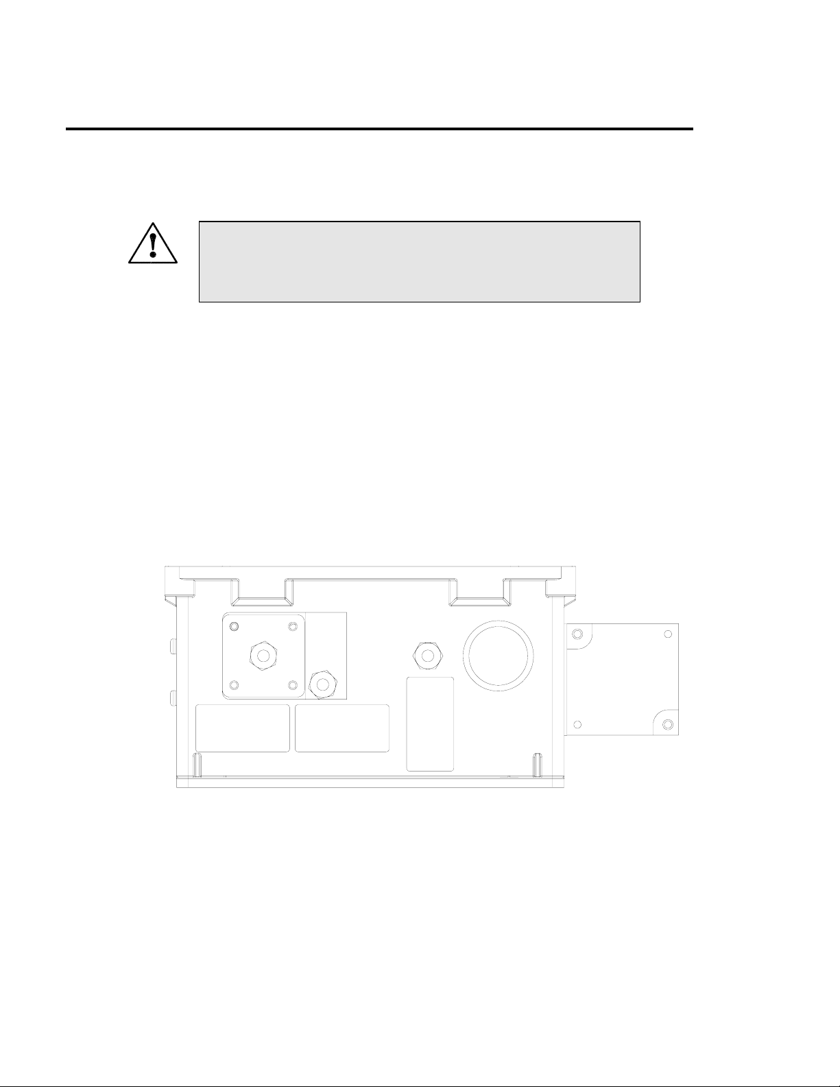
2.1 Mechanical Installation
1. Mount the enclosure securely to a vertical surface. Figure 2-1 below shows the
locations of the four mounting holes. All four mounting holes should be used to
secure the monitor.
6.050 [153.67]
10.700 [271.78]
Figure 2-1 Mounting Hole Locations
P/N 03662D Teledyne API Model 460H O3 Monitor Operator Manual - Page 11
Page 12
2.2 Pneumatic Connections
1. Connect a ¼” exhaust line to the fitting labeled ‘Exhaust.’ This line should be vented
to an outside area, since the exhaust gas may still contain trace levels of ozone that may
not be completely removed by the built-in the ozone scrubber.
CAUTION
Exhaust gas from the M460H may contain dangerous levels of
2. Connect the ozone delivery line to the ¼” inlet fitting labeled “Ozone Inlet” on the
bottom face of the enclosure (See Figure 2-2.) The ozone delivery should be
regulated to no more than 30psig. All tubing used should be made of ozone resistant
material such as PTFE(Teflon™) or FEP. API can supply appropriate tubing for
connecting the ozone supply line.
3. Connect the oxygen or other zero gas source to the ¼” tube fitting labeled ‘Zero Gas
Inlet.’ Zero Gas supply pressure should be regulated between 5 and 30 psig.
4. The gas flow rate through the monitor should be established between 0.5 and 2.0
L/min.
ozone!
OZONE INLET
WARNING - DO NOT EXCEED
30 PSIG GAS DELIVERY
PRESSURE
ZERO GAS INLET
WARNING - DO NOT EXCEED
30 PSIG GAS DELIVERY
PRESSURE
OF OZONE
EXHAUST
WARNING - THIS GAS MAY
CONTAIN HARMFUL LEVELS
Figure 2-2 Pneumatic Connections
P/N 03662D Teledyne API Model 460H O3 Monitor Operator Manual - Page 12
Page 13

2.3AC Power Connection
Connect AC power to the instrument. A hole is provided on the bottom face of the
enclosure for installing a ½” conduit fitting for routing the electrical wiring into the
instrument. In order to maintain the IP (NEMA4X) rating of the enclosure, an
appropriate sealed conduit connector should be used. Figure 2-3 below shows the
location of the three terminal connector for the AC power. It is recommended that if
multi-strand wires are used to make the AC connections, the wire ends should first be
“tinned” with solder to ensure that the screw terminals can make a reliable connection to
the wires.
CAUTION!
Disconnect power to the AC mains before making any electrical
connections to the Model 460H.
IMPORTANT!
A proper earth ground connection must be made to the receptacle
labeled “Earth Ground” on the 3 pin AC connector. Failure to do
so may result in a shock hazard and malfunction of the
instrument.
P/N 03662D Teledyne API Model 460H O3 Monitor Operator Manual - Page 13
Page 14

EARTH GROUND
AC LINE
AC NEUTRAL
I/O CONNECTOR
AC POWER CONNECTOR
Figure 2-3 Electrical Connections
2.4 Electrical I/O Connections
All user I/O connections are available on the 16 pin connector on the mainboard (See
Figure 2-3 for location.) This connector can be unplugged from the header on the
mainboard for easier access when wiring. To disconnect from mainboard, loosen the two
retaining screws at either end of the connector.
When connecting multi-strand wire to this connector, the wire ends should be “tinned”
with solder to ensure a reliable connection. This is not necessary if solid-core wire is
used.
2.4.1 Analog Output
The analog output is located on the two pins labeled ‘Analog Out +’ and ‘Analog Out –‘
The analog output can be configured for voltage or current output. The standard output is
a 0-5 volt output. The analog output can also be optionally configured for a 4-20mA
Current output. Check the serial number tag on the instrument to determine Analog
Output configuration.
P/N 03662D Teledyne API Model 460H O3 Monitor Operator Manual - Page 14
Page 15

2.4.2 Digital Status Outputs
The M460H has four digital status outputs for indicating error and operational status
conditions. These outputs are in the form of opto-isolated open-collector transistors.
They can be used to drive status LED’s on a display panel or interface to a digital device
such as a Programmable Logic Controller (PLC).
Figure 2-4 shows the most common way of connecting the digital outputs to an external
device such as PLC. Note: Most devices, such as PLC’s, have internal provision for
limiting the current that the input will draw from an external device. When connecting to
a unit that does not have this feature, external dropping resistors must be used to limit the
current through the transistor output to 50mA or less.
See Chapter 7 for details on using the Status Outputs for diagnosing sensor and systemlevel malfunctions.
Table 2-1 below describes the function of the status outputs.
Table 2-1 Digital Status Output Pins
Label Name Operation
STATUS OUT 1 Sensor O.K. Normally On
STATUS OUT 2 Invalid Reading Normally Off
STATUS OUT 3 Lamp Low Normally Off
STATUS OUT 4 Cell Dirty Normally Off
STATUS OUT 5 Auto-Zero Error Normally Off
STATUS OUT 6 Spare Undefined
STATUS COM Common Pin for
all Status Outputs
N/A
Programmable Logic
Controller or other devi ce
+5V
Digital
Input
Opto-Isolator
M454
Digital Output #1-4 (Collector)
Digital Output Common (Emmiter)
Ground Provided
by PLC
Figure 2-4 Digital Output Connections
P/N 03662D Teledyne API Model 460H O3 Monitor Operator Manual - Page 15
Page 16

2.4.3 Control Inputs
There are 2 digital control inputs on the I/O connector; they are labeled ‘Zero Input’ and
‘Aux Input.’ The control inputs are used for remote control of the M460H by a device
such as a PLC. These inputs are triggered by providing a contact closure or low
impedance current path between the Input and the Gnd pin. This can be done by using a
mechanical switch or isolated transistor type output from another device, such as a PLC.
Never connect a voltage level output from another device to these contacts. The
functions of the control inputs is summarized below in Table 2-2:
Table 2-2 Control Inputs
Input Description
Zero Input Zero Calibration
Aux Input Pressure Display
Zero Calibration Input:
The zero calibration input is used to initiate zero calibration from an external device.
This input performs exactly the same function as the ‘Zero’ buttons on the front panel.
Pressure Display Input:
The pressure display input is used to display the pressure on the front panel. This input
performs exactly the same function as the ‘Pressure’ buttons on the front panel.
P/N 03662D Teledyne API Model 460H O3 Monitor Operator Manual - Page 16
Page 17

2.4.4 RS232/RS485 Serial Communications Port
A bi-directional RS232/485 Serial Port Interface is provided that can be used for data
acquisition and instrument control. All that is required to use this interface is a computer
with a serial communications port (COM port) and terminal software. Three pins are
provided on the I/O connector for serial communications as shown in Table 2-3.
Table 2-3 Serial Port Pins
Label Description
SERIAL TX Serial Transmit (RS485 – A)
SERIAL RX Serial Receive (RS485 – B)
SERIAL GND Serial Ground (RS232 Only)
The Serial Port can be configured for either RS232 or RS485. The standard factory
configuration is RS232. For direct connection to a PC or Laptop, RS232 should be used.
For a permanent connection into a data acquisition system, RS485 is recommended
because it has better noise immunity and is more reliable when communicating over
longer distances. See Appendix A for details on changing the Serial Port configuration.
Figure 2-5 below shows typical connections using RS232 and RS485. Note that the
RS485 connection does not use the SERIAL GND pin.
DB9-FEMALE
SERIAL GND
SERIAL RX
SERIAL TX
RS232
SERIAL TX
SERIAL RX
RS485-A
RS485-B
RS485
Figure 2-5 Typical RS232 and RS485 Connections
See Chapter 5 for information on the Serial Communications protocol used by the
M460H.
P/N 03662D Teledyne API Model 460H O3 Monitor Operator Manual - Page 17
Page 18

3.0 Startup
Perform the following steps when fist installing the M460H ozone monitor or when
bringing the monitor back into service.
1. Turn on power to the monitor. The display will briefly display the “API” logo
followed by the software version. The display will then begin showing ozone
concentration.
2. Establish a flow of zero gas to the monitor. Zero gas can be oxygen or clean, dry air.
If monitor cannot be disconnected from an ozone generator, then establish flow
through the generator and monitor with the generator turned off. Flow rate through
monitor should be between 0.5 – 2.0 LPM (Liters per minute.)
3. Let monitor warm up and purge for a minimum of 5 minutes. Zero the monitor by
simultaneously pressing the Zero buttons on the front panel. The display should
momentarily show dashes (‘----‘) after which the display should go quickly to zero.
4. Check Status LED’s on front panel; Sensor OK led should be ON, all other LED’s
should be OFF. If the Status LED’s are not in this state, refer to Chapter 7 for
troubleshooting information.
5. Observe the monitor for several more minutes at zero to ensure that it is stable.
6. The monitor is now ready to measure ozone.
P/N 03662D Teledyne API Model 460H O3 Monitor Operator Manual - Page 18
Page 19

4.0 Operation
The M460H has been designed for simple and trouble-free operation. The Sections
below detail the operational features of the M460H.
4.1 Front Panel Display
4.1.1 O3 readout
The current ozone concentration is displayed in the 4 digit readout in the center of the
display. The concentration is displayed in the currently selected units, either wt% or
g/Nm3.
4.1.2 Pressure Display
The pressure inside the measurement cell can be displayed on the readout by pressing and
holding the ‘Pressure’ key on the front panel. The pressure is displayed in units of psia
(pounds per square inch absolute.) The normal ambient pressure at sea level is about
14.7psia. Ambient pressure at higher elevations will be somewhat less.
The M460H can accurately measure ozone at cell pressures of 12 - 20psia. Care should
be taken in setting up the monitor to avoid over-pressurizing the cell, as this will result in
erroneous readings.
4.1.3 Zero Calibration
A Zero Calibration can be performed on the monitor at any time by simultaneously
pressing the two ‘Zero’ buttons on the front panel. The monitor will briefly display
dashes (‘----‘) after which the concentration should quickly go to zero.
The Zero Calibration is calculated based on the current measurement in the cell; so care
must be taken to ensure that all ozone is purged from the cell before pressing the ‘Zero’
buttons.
If the Auto-Zero option is not used, API recommends performing a manual Zero
Calibration on the monitor once a week.
4.1.4 Status LED’s
The four status LED’s to the right of the display indicate the general status of the Model
460H Monitor. During normal operation, after the monitor has warmed up, the green
‘Sensor OK’ LED should be on and all other Status LED’s should be off. For
information on troubleshooting using the Status LED’s, see Chapter 7.
P/N 03662D Teledyne API Model 460H O3 Monitor Operator Manual - Page 19
Page 20

4.2 Auto-Zero Operation
The Auto-Zero feature allows the monitor to operate unattended for extended periods of
time. This feature automatically performs a Zero Calibration at specific intervals (default
interval is 12hrs.) The monitor does this by opening a solenoid valve to allow externally
supplied Zero Gas to purge the monitor and then automatically performs a Zero
Calibration.
4.2.1 Auto-Zero Installation
In order for this feature to function properly, external, pressurized zero gas must be
supplied to the monitor as detailed in Section 2.2.
4.2.2 Auto-Zero Function
When the Auto-Zero function is triggered, the monitor performs the steps outlined in
Table 4-1 below.
Table 4-1 Auto-Zero Function
Step Function Display Reads
1 Switch Auto-Zero valve on N/A
2 Purge cell for 20 seconds Holds and Flashes Concentration Value
3 Perform Zero Calibration Dashes: ‘----‘
4 Switch Auto-Zero valve off Dashes: ‘----‘
5 Hold-Off for 3 sec to return
Measurement Gas to cell
6 Return to Measurement Mode Normal Concentration Display
4.2.3 Auto Zero Error
Dashes: ‘----‘
When performing an Auto-Zero Calibration, the monitor checks to make sure the ozone
concentration is near zero before calibration. If the ozone concentration is above 0.5wt%
or 5.0 g/Nm3, the monitor will not perform the calibration and will display a “ZERO
ERR” message on the display. The monitor will also turn on the Auto-Zero Error status
signal (See Section 2.4.2 Digital Status Outputs.) This Status Signal will remain on until
another Auto-Zero Calibration is successfully performed or a Manual Zero Calibration is
performed.
If an Auto-Zero error is detected, a manual Zero Calibration should be performed (See
Section 4.1.3 Zero Calibration.)
P/N 03662D Teledyne API Model 460H O3 Monitor Operator Manual - Page 20
Page 21

5.0 Serial Communications
The M460H comes equipped with a powerful digital Serial Communications Port that
can be used for Data Acquisition and for changing instrument configuration. This port
can be configured for either RS232 or RS485(half-duplex) operation. See Section 2.4.4
for details on connecting the port to a computer or Data Acquisition system.
5.1 Serial Port Configuration
The Serial Port of the device being used to communicate with the M460H should be
configured as follows:
Table 5-1 Serial Port Configuration
Parameter Value
Baud Rate 9600 bps
Data Bits 8
Stop Bits 1
Parity None
5.2 Command Syntax
All characters sent and received are standard Ascii characters and all numbers are
decimal numbers converted to Ascii text.
All commands are sent using the following syntax:
<address><command>:<data1>,<data2>#<checksum><CR>
Where:
address is the instrument address(default =1)
command is the command string being sent
: (colon) is the data separator and is only included if data is being sent as part of the
command (See Command Details below to see if a command requires data or
not)
data1 is the first data parameter, if required.
data2 is the second data parameter, if required.
# is the Checksum separator, sent only if optional checksum is included
checksum is an Ascii checksum of all characters up to the # character. The checksum is
optional, commands sent without the checksum(and checksum separator,) are
also valid.
CR is a carriage return, Ascii 13.
P/N 03662D Teledyne API Model 460H O3 Monitor Operator Manual - Page 21
Page 22

Examples of valid Commands with no data:
Checksum Included:
1O3#179<CR>
No Checksum:
1O3<CR>
Examples of valid Commands with data:
Checksum Included:
1VSET:1,20#620<CR>
No Checksum:
1VSET:1,20<CR>
5.3 Command Summary
Table 5-2 below lists the commands available and a summary of their function.
Table 5-2 Serial Port Command Summary
Command Description
CAUTO Perform an Auto-Zero Calibration (if option is installed)
CZERO Perform a manual zero calibration (zero calibration is
computed based on current O3 reading in cell)
DACSTEP Analog Output Test Mode, Step Function
O3 Returns current O3 concentration
SETADDR Set communications address
TDUMP Returns a compact list of current measurement parameters
TLIST Returns all current measurement parameters
VGET Get Single VAR value
VLIST Lists all internal VARS
VSET Sets value of internal VAR
P/N 03662D Teledyne API Model 460H O3 Monitor Operator Manual - Page 22
Page 23

5.4 Command Reference
5.4.1 CAUTO
Syntax
<address>CAUTO<CR>
Description
Perform an Auto-Zero Calibration. Valid only if Auto-Zero option is installed in
monitor.
Data Parameters Sent
None
Response <address>:<success_flag>#<checksum><CR>
Example
Command:
1CAUTO<CR>
Response:
1:OK#261<CR> - Calibration Successful
1:FAIL#391<CR> - Calibration Failed
P/N 03662D Teledyne API Model 460H O3 Monitor Operator Manual - Page 23
Page 24

5.4.2 CZERO
Syntax
<address>CZERO<CR>
Description
Perform a Zero Calibration. Note that calibration is performed based on concentration
currently in measurement cell. Instrument should be sufficiently purged with zero gas
before issuing this command.
Data Parameters Sent
None
Response <address>:<success_flag>#<checksum><CR>
Example
Command:
1CZERO<CR>
Response:
1:OK#261<CR> - Calibration Successful
1:FAIL#391<CR> - Calibration Failed
P/N 03662D Teledyne API Model 460H O3 Monitor Operator Manual - Page 24
Page 25

5.4.3 DACSTEP
Syntax
<address>DACSTEP<CR>
Description
Puts instrument in the Analog Output setup mode. The Analog Output steps from zero to
full-scale in 20% increments, pausing for 4 seconds at each level. This repeats 5 times,
after which the instrument returns to normal operation. This mode is useful for testing
the Analog Output and the operation of any equipment measuring the Analog Output.
Data Parameters Sent
None
Response <address>:<success_flag>#<checksum><CR>
Example
Command:
1DACSTEP<CR>
Response:
1:OK#261<CR> - Calibration Successful
1:FAIL#391<CR> - Calibration Failed
Notes
Note that the DACSTEP function takes some time to complete. When the command is
sent to the monitor, it will immediately respond with the <address> and colon ‘:’ as an
acknowledgement that the message was received. After the function is complete the rest
of the response will be sent. No additional commands should be issued to the monitor
until the function completes.
P/N 03662D Teledyne API Model 460H O3 Monitor Operator Manual - Page 25
Page 26

5.4.4 O3
Syntax
<address>O3<CR>
Description
Returns the current ozone concentration measured by the monitor.
Data Parameters Sent
None
Response <address>:<o3_conc>#<checksum><CR>
Example
Command:
1O3<CR>
Response:
1:12.01898#518<CR> - Current O3 Concentration (reading 12.02 wt%)
Notes
Note that the concentration value returned shows more digits after the decimal than the
front panel display. Concentration values should only be considered valid to 4 significant
digits.
P/N 03662D Teledyne API Model 460H O3 Monitor Operator Manual - Page 26
Page 27

5.4.5 SETADDR
Syntax <address>SETADDR:<new_address><CR>
Description
Changes the communications address to a new value.
Data Parameters Sent
new_address is the new address for the monitor; Range for new_address is 1-9.
Response <address>:<success_flag>#<checksum><CR>
Example
Command:
1SETADDR:2<CR> - Change address from 1 to 2
Response:
1:OK#261<CR> - Change Address Successful
1:FAIL#391<CR> - Change Address Failed
Notes
Note that monitor response is from previous address, but any further commands must be
at new address. In the example above, after sending back the OK response, the monitor
will no longer respond to commands with address 1.
P/N 03662D Teledyne API Model 460H O3 Monitor Operator Manual - Page 27
Page 28

5.4.6 TDUMP
Syntax
<address>TDUMP<CR>
Description
Returns the current measured parameters: O3 Concentration, Cell Pressure(psia,) Cell
Temperature (K,) Lamp Temperature (K,) Measure Detector (mV,) Calibrated
Refererence Detector (mV,) Reference Detector (mV)
Data Parameters Sent
None
Response
<address>:<o3_conc>,<pressure>,<cell_temp>,<lamp_temp>,<measure>,<cal_ref>,<ref
erence>#<checksum><CR>
Example
Command:
1TDUMP<CR>
Response:
1:0.0282144,14.77461,300.7179,324.7713,2881.437,2940.903,4412.52#3228
<CR>
Notes
Note that the concentration value returned shows more digits after the decimal than the
front panel display. Concentration values should only be considered valid to 4 significant
digits.
P/N 03662D Teledyne API Model 460H O3 Monitor Operator Manual - Page 28
Page 29

5.4.7 TLIST
Syntax
<address>TLIST<CR>
Description
Returns a verbose list of the current measured parameters with labels for each parameter:
O3 Concentration, Cell Pressure(psia,) Cell Temperature (K,) Lamp Temperature (K,)
Measure Detector (mV,) Calibrated Reference Detector (mV,) Reference Detector (mV)
Data Parameters Sent
None
Response
Test Parameter List (See Below)
Example
Command:
1TLIST<CR>
Response:
O3 = 0.0226168
Press = 14.7753
Cell Temp = 300.7116
Lamp Temp = 324.7965
Ref = 2881.52
Meas = 2941.092
Raw Ref = 4412.646
Notes
Note that the concentration value returned shows more digits after the decimal than the
front panel display. Concentration values should only be considered valid to 4 significant
digits.
Also, note that no checksum is sent in the response to the TLIST command.
P/N 03662D Teledyne API Model 460H O3 Monitor Operator Manual - Page 29
Page 30

5.4.8 VGET
Syntax <address>VGET:<var_index><CR>
Description
Returns value of an internal configuration variable (VAR.)
Data Parameters Sent
var_index is index number for internal VAR as follows:
Var
Index
0 analog_range Full-Scale concentration
1 azero_enable Auto-Zero Enable VAR.
2 azero_period Period for Auto-Zero
3 carrier_weight Mol weight of carrier gas
4 comm_mode Not Used N/A
5 iir_filt Digital Concentration
Name Description Allowable Range
5.0 – 400.0 (Units are
range for Analog Output
scaling
current unit of measure,
wt% or g/Nm3)
0 = Off
(only valid if Auto-Zero
1 = On
hardware is installed)
5.0 - 86400.0 Seconds
Calibration timer
27.0 – 32.0 mol weight
for wt% calculations (32.0
= O2)
0.05 – 1.0
filter
(1.0 = No Filtering, lower
values increases filtering)
6 conc_units O3 Concentration
measurement units
0 = wt%
1 = g/Nm3
Response <address>:<var_value>#<checksum><CR>
Example
Command:
1VGET:0<CR> - Request analog_range value
Response:
1:15.0#303 - analog_range returned as 15.0 (wt%)
P/N 03662D Teledyne API Model 460H O3 Monitor Operator Manual - Page 30
Page 31

5.4.9 VLIST
Syntax
<address>VLIST<CR>
Description
Returns a verbose list of an internal configuration variables (VARs.)
Data Parameters Sent
None
Response
Var List (See Below)
Example
Command:
1VLIST<CR>
Response:
#0 analog_range = 15.0
#1 azero_enable = 0.0
#2 azero_period = 720.0
#3 carrier_weight =32.0
#4 comm_mode = 0.0
#5 iir_filt = 0.4
#6 conc_units = 0.0
Notes
Note that no checksum is sent in the response to the VLIST command.
P/N 03662D Teledyne API Model 460H O3 Monitor Operator Manual - Page 31
Page 32

5.4.10 VSET
Syntax <address>VSET:<var_index>,<new_value><CR>
Description
Sets value of an internal configuration variable (VAR.)
Data Parameters Sent
var_index is index number for internal VAR (See VGET for index list)
new_value new value for VAR.
Response <address>:<var_value>#<checksum><CR>
Example
Command:
1VSET:0,15.0<CR> - Set analog_range VAR to 15.0 (wt%)
Response:
1:OK#261<CR> - VSET Successful
1:FAIL#391<CR> - VSET Failed
P/N 03662D Teledyne API Model 460H O3 Monitor Operator Manual - Page 32
Page 33

6.0 Maintenance
6.1 Replacing the gas filter element
The Model 460H is equipped with a gas filter on the ozone inlet. These filters accept
25mm diameter glass fiber elements. Only filter elements of borosilicate glass or quartz
fibers should be used. When the instrument is first installed, the sample filters should be
checked at least once a week for particulate loading and replaced if necessary. Once the
replacement frequency is determined, a regular schedule for filter replacement should be
instituted.
For replacement 25mm filter elements, please contact API’s sales department and request
part number 02851.
Filter Replacement Procedure:
1. First ensure that the gas delivery line is not under pressure and has been purged of
ozone.
2. Remove the four screws securing the gas filter assembly.
3. Remove the bottom half of the filter housing
4. Examine the internal sealing o-ring and replace if necessary.
5. Pull out the stainless steel screen securing the filter element.
6. The element can now be removed and replaced. When re-assembling filter, make
sure that the top stainless steel screen is pushed into the filter cavity, securing the
element in place.
7. After re-assembly, the gas line should be pressurized with oxygen or dry air and
checked for leaks using a bubble solution.
6.2 Cleaning Exterior Surfaces of the M460H
If necessary, the exterior surfaces of M454H can be cleaned with a damp cloth. Do not
attempt to clean any of the other surfaces of the instrument. Do not submerge any part of
the instrument in water or cleaning solution.
6.3 Degree of Protection
The Model 460NEMA has a water ingress rating of IPX65 which indicates that it can
withstand strong jets of water and is totally protected against dust.
P/N 03662D Teledyne API Model 460H O3 Monitor Operator Manual - Page 33
Page 34

7.0 Sensor and System Troubleshooting
This chapter gives guidelines for diagnosing system and sensor malfunctions using the
five digital Status Outputs provided by the M460H. All troubleshooting should be done
after the M460H has been turned on and allowed to warm up for at least 15 minutes.
7.1 Status Output Summary
Table 7-1 below gives a summary of the operation of the five Status Outputs on the
M454H. See 2.4.2 Digital Status Outputs for information on connecting these outputs.
Table 7-1: Digital Status Outputs
Output
#
1 Sensor O.K. Normal State Reference or
2 Invalid Reading Pressure > 45 psia,
3 Lamp Low Reference
4 Cell Dirty Measure/Reference
5 Auto-Zero Error Auto-Zero Failed Normal State
Name On State Off state
Measure > 4995mV;
Reference < 1000mV
Normal State
Negative Ozone
Concentration,
Concentration Over-
Range
Normal State
Detector<2500mV
Normal State
ratio < 0.5 (zero gas)
7.2 Sensor OK
The normal state for the Sensor OK output in ON. During the warm-up period on startup this output will stay off until the UV lamp reaches a minimum intensity. If this output
remains off after the 15 minute warm-up period, or goes off during normal operation,
then the M460H is in need of servicing.
If the Sensor O.K. output turns off AND the Lamp Low output is on, this indicates that
the lamp intensity has below the minimum level required for proper operation.
If the Sensor O.K. output turns off and the Lamp Low output is also off, then one of the
analog voltages in the sensor has exceeded the range of the internal A/D converter.
Adjustment by qualified service personnel is required.
P/N 03662D Teledyne API Model 460H O3 Monitor Operator Manual - Page 34
Page 35

7.3 Invalid Reading
The normal state for the Invalid Reading output is OFF. If this output turns on, this
indicates that the M460H is still operational, but a system fault or calibration fault exists
that may make the current ozone reading invalid.
The Invalid Reading output is turned on for any of the following conditions:
1. When the measured pressure in the measurement cell exceeds 45 psia.
2. When the measured concentration has exceeded the full-scale concentration
range of the sensor. Check the serial number tag for the full-scale concentration
range.
3. The sensor is indicating an excessive negative reading.
7.4 Lamp Low
The normal state for the Lamp Low output is OFF. If this output turns on, this indicates
that the UV lamp intensity as measured by the reference detector has dropped below
2500mV.
If the Lamp Low output turns ON and the Sensor O.K. output is ON, this indicates that
the lamp intensity is still adequate for measurement, but adjustment should be made
when possible.
If the Lamp Low output turns ON and the Sensor O.K. output is OFF, this indicates a
failure condition and measurement is no longer possible.
7.5 Cell Dirty
The normal state for the Cell Dirty output is OFF. If this output turns on, then the ratio
of the measure detector to the reference detector (at zero) is < 0.5. This value is
calculated when the zero calibration is performed.
When this output is on, it indicates a loss of optical transmission through the windows in
the absorption cell or a calibration fault.
P/N 03662D Teledyne API Model 460H O3 Monitor Operator Manual - Page 35
Page 36

7.6 Status Output Summary Table
Table 7-2 below is a logic truth table summarizing the recommended actions based on the
states of the four status outputs. A ‘1’ indicates the output is ON, a ‘0’ indicates the
output is OFF, and ‘X’ indicates the output is in either state.
Table 7-2: Status Output Truth Table
Sensor
OK
1 0 0 0 Normal operation, no action
0 X X X Service required
1 1 X X Check Pressure > 45 psia
1 X 1 X Lamp adjustment useful,
1 X X 1 Calibrate at zero
Invalid
Reading
Lamp
Low
Cell
Dirty
Actions
required
Verify that concentration has
not exceeded full scale range
of sensor.
Calibrate at Zero.
though not required
Clean Cell
P/N 03662D Teledyne API Model 460H O3 Monitor Operator Manual - Page 36
Page 37

Appendix A – Serial Port Configuration
To configure the com port for RS232 or RS485, move the 4 shunts on JP3 of the
Controller PCA (#03492) to the proper position as shown in Figure A-1.
RS232 RS485
Figure A-1 RS232/RS485 Jumpers (Controller PCA#03492)
P/N 03662D Teledyne API Model 460H O3 Monitor Operator Manual - Page 37
Page 38

Appendix B – Pneumatic Diagram
O3 Gas In
Zero Gas In
Exhaust Out
Filter
Azero Valve
Flow Control
Orifice
O3
Measurement
Cell
Flow-Meter
O3 Destruct
P/N 03662D Teledyne API Model 460H O3 Monitor Operator Manual - Page 38
 Loading...