

Page 1
4220 Submerged Probe
Flow Meter
Installation and Operation Guide
Part #60-3223-130 of Assembly #60-3224-052
Copyright © 2001. All rights reserved, Teledyne Isco, Inc.
Revision T, March 6, 2006
Page 2

Page 3

Foreword
This instruction manual is designed to help you gain a thorough understanding of the
operation of the equipment. Teledyne Isco recommends that you read this manual
completely before placing the equipment in service.
Although Teledyne Isco designs reliability into all equipment, there is always the possibility of a malfunction. This manual may help in diagnosing and repairing the malfunction.
If the problem persists, call or e-mail the Teledyne Isco Technical Service Department
for assistance. Simple difficulties can often be diagnosed over the phone.
If it is necessary to return the equipment to the factory for service, please follow the
shipping instructions provided by the Customer Service Department, including the
use of the Return Authorization Number specified. Be sure to include a note
describing the malfunction. This will aid in the prompt repair and return of the
equipment.
Teledyne Isco welcomes suggestions that would improve the information presented in
this manual or enhance the operation of the equipment itself.
Teledyne Isco is continually improving its products and reserves the right to
change product specifications, replacement parts, schematics, and instructions without notice.
Customer Service
Phone: (800) 228-4373 (USA, Canada, Mexico)
Fax: (402) 465-3022
Email: IscoCSR@teledyne.com
Technical Service
Phone: (800) 775-2965 (Analytical)
Email: IscoService@teledyne.com
Return equipment to: 4700 Superior Street, Lincoln, NE 68504-1398
Other Correspondence
Mail to: P.O. Box 82531, Lincoln, NE 68501-2531
Email: IscoInfo@teledyne.com
Web site: www.isco.com
Contact Information
(402) 464-0231 (Outside North America)
(800) 228-4373 (Samplers and Flow Meters)
Revised September 15, 2005
Page 4

Page 5
4220 Flow Meter
Safety
4220 Flow Meter
Safety
General Warnings Before installing, operating, or maintaining this equipment, it is
imperative that all hazards and preventive measures are fully
understood. While specific hazards may vary according to
location and application, take heed in the following general
warnings:
WARNING
Liquids associated with this instrument may be classified
as carcinogenic, biohazard, flammable, or radioactive.
Should these liquids be used, it is highly recommended that
this application be accomplished in an isolated
environment designed for these types of materials in
accordance with federal, state, and local regulatory laws,
and in compliance with your company’s chemical/hygiene
plan in the event of a spill.
WARNING
Avoid hazardous practices! If you use this instrument in
any way not specified in this manual, the protection
provided by the instrument may be impaired.
WARNING
If this system uses flammable organic solvents, Isco
recommends that you place this system in a well-ventilated
environment, designed for these types of materials. This
environment should be constructed in accordance with
federal, state, and local regulations. It should also comply
with your organization’s plan concerning chemical and
hygiene mishaps. In all cases use good laboratory
practices and standard safety procedures.
Hazard Severity Levels This manual applies Hazard Severity Levels to the safety alerts,
These three levels are described in the sample alerts below.
CAUTION
Cautions identify a potential hazard, which if not avoided, may
result in minor or moderate injury. This category can also warn
you of unsafe practices, or conditions that may cause property
damage.
WARNING
Warnings identify a potentially hazardous condition, which
if not avoided, could result in death or serious injury.
Page 6
4220 Flow Meter
Safety
Hazard Symbols The equipment and this manual use symbols used to warn of
Warnings and Cautions
DANGER
DANGER – limited to the most extreme situations
to identify an imminent hazard, which if not
avoided, will result in death or serious injury.
hazards. The symbols are explained below.
Hazard Symbols
The exclamation point within the triangle is a warning sign alerting you of
important instructions in the instrument’s technical reference manual.
The lightning flash and arrowhead within the triangle is a warning sign alerting you of “dangerous voltage” inside the product.
Symboles de sécurité
Warnungen und Vorsichtshinweise
Advertencias y Precauciones
Ce symbole signale l’existence d’instructions importantes relatives au produit dans ce manuel.
Ce symbole signale la présence d’un danger d’électocution.
Das Ausrufezeichen in Dreieck ist ein Warnzeichen, das Sie darauf
aufmerksam macht, daß wichtige Anleitungen zu diesem Handbuch
gehören.
Der gepfeilte Blitz im Dreieck ist ein Warnzeichen, das Sei vor “gefährlichen
Spannungen” im Inneren des Produkts warnt.
Esta señal le advierte sobre la importancia de las instrucciones del manual
que acompañan a este producto.
Esta señal alerta sobre la presencia de alto voltaje en el interior del
producto.
Page 7

4220 Flow Meter
Safety
IMPORTANT – PLEASE READ
WARNING
The installation and use of this product may require you to work in locations where
you could be seriously injured or even
killed.
sary to ensure your safety before entering the installation.
pervised. Install and operate this product in accordance with all applicable safety and
health regulations, as well as any appropriate local ordinances.
This product is often installed in confined spaces. Examples of confined spaces are manholes, pipelines,
digesters, and storage tanks. These places can be dangerous or fatal if you are not suitably prepared. The
primary hazards are the presence of poisoned air, the lack of ventilation, and the possibility of falls. Other
hazards may be present, as well. Work in such places is governed by OSHA 1910.146, and may require a
permit before entering.
Material Safety Data Sheets (MSDS) for chemical agents supplied or recommended for use with this
product are in the MSDS Appendix. These sheets provide information about possible hazards from the
chemicals. Additional MSDS, covering various proprietary agents (name-branded or trademarked mix-
tures) that can also be used with this product, are available from the manufacturers of those agents.
Take whatever precautions are neces-
Never
work alone or unsu-
NOTE
FLOWLINK is a registered trademarks of Isco Inc. All other brand or product names used in this manual are trademarks
or registered trademarks of their respective companies and/or organizations.
This manual uses the following notations to set
apart hazard warnings and notes:
DANGER
DANGER describes situations which if not
will
avoided,
result in loss of life or serious
personal injury. The emphasis is on a clear
and immediate threat to your life or safety.
WARNING
WARNING describes situations which if not
result in loss of life or serious per-
avoided,
sonal injury. The emphasis here is on the
tial
could
poten-
for a serious accident.
CAUTION describes situations which if not avoided,
may result in moderate personal injuries, property
damage, or damage to the equipment.
NOTES draw your attention to specific features, practices, or other information useful in setting up or
installing the product.
CAUTION
NOTE
Page 8

4220 Flow Meter
Safety
Page 9

4220 Flow Meter
Table of Contents
Section 1 Introduction
1.1 Description. . . . . . . . . . . . . . . . . . . . . . . . . . . . . . . . . . . . . . . . . . . . . . . . . . . . . . . . . 1-1
1.2 Compatible Equipment . . . . . . . . . . . . . . . . . . . . . . . . . . . . . . . . . . . . . . . . . . . . . . . 1-1
1.3 Operating Principles . . . . . . . . . . . . . . . . . . . . . . . . . . . . . . . . . . . . . . . . . . . . . . . . . 1-2
1.3.1 Submerged Probe Operation . . . . . . . . . . . . . . . . . . . . . . . . . . . . . . . . . . . . . 1-3
1.3.2 Transducer Operation . . . . . . . . . . . . . . . . . . . . . . . . . . . . . . . . . . . . . . . . . . 1-3
1.3.3 Two Probes Available . . . . . . . . . . . . . . . . . . . . . . . . . . . . . . . . . . . . . . . . . . 1-4
1.4 Software Upgrades . . . . . . . . . . . . . . . . . . . . . . . . . . . . . . . . . . . . . . . . . . . . . . . . . . 1-4
1.5 Controls, Indicators, and Connectors. . . . . . . . . . . . . . . . . . . . . . . . . . . . . . . . . . . . 1-4
1.6 Technical Specifications . . . . . . . . . . . . . . . . . . . . . . . . . . . . . . . . . . . . . . . . . . . . . . 1-8
1.7 How to Make Battery Calculations . . . . . . . . . . . . . . . . . . . . . . . . . . . . . . . . . . . . 1-10
1.7.1 Current Draw . . . . . . . . . . . . . . . . . . . . . . . . . . . . . . . . . . . . . . . . . . . . . . . . 1-12
Section 2 Programming
2.1 Getting Started . . . . . . . . . . . . . . . . . . . . . . . . . . . . . . . . . . . . . . . . . . . . . . . . . . . . . 2-1
2.1.1 Operation of the Display . . . . . . . . . . . . . . . . . . . . . . . . . . . . . . . . . . . . . . . . 2-1
2.1.2 Keypad Functions . . . . . . . . . . . . . . . . . . . . . . . . . . . . . . . . . . . . . . . . . . . . . 2-2
2.2 Programming Procedure . . . . . . . . . . . . . . . . . . . . . . . . . . . . . . . . . . . . . . . . . . . . . . 2-3
2.3 Description of Program Steps. . . . . . . . . . . . . . . . . . . . . . . . . . . . . . . . . . . . . . . . . . 2-5
2.3.1 Step 1, Operating Mode . . . . . . . . . . . . . . . . . . . . . . . . . . . . . . . . . . . . . . . . . 2-5
2.3.2 Step 2, Flow Conversion Type . . . . . . . . . . . . . . . . . . . . . . . . . . . . . . . . . . . . 2-6
2.3.3 Step 3 - Adjust Level, Parameters . . . . . . . . . . . . . . . . . . . . . . . . . . . . . . . . 2-7
2.3.4 Step 4 - Reset Totalizer . . . . . . . . . . . . . . . . . . . . . . . . . . . . . . . . . . . . . . . . . 2-8
2.3.5 Step 5 - Sampler Pacing . . . . . . . . . . . . . . . . . . . . . . . . . . . . . . . . . . . . . . . . 2-8
2.3.6 Step 6 - Sampler Enable . . . . . . . . . . . . . . . . . . . . . . . . . . . . . . . . . . . . . . . . 2-9
2.3.7 Step 7 - Alarm Dialout Mode . . . . . . . . . . . . . . . . . . . . . . . . . . . . . . . . . . . . 2-10
2.3.8 Step 8 - Printer . . . . . . . . . . . . . . . . . . . . . . . . . . . . . . . . . . . . . . . . . . . . . . 2-10
2.3.9 Step 9 - Reports/History . . . . . . . . . . . . . . . . . . . . . . . . . . . . . . . . . . . . . . . 2-10
2.4 Interpreting the Program Screens . . . . . . . . . . . . . . . . . . . . . . . . . . . . . . . . . . . . . 2-11
2.4.1 Operating Mode . . . . . . . . . . . . . . . . . . . . . . . . . . . . . . . . . . . . . . . . . . . . . . 2-11
2.4.2 Optional Outputs . . . . . . . . . . . . . . . . . . . . . . . . . . . . . . . . . . . . . . . . . . . . . 2-15
2.4.3 Step 1 - Program . . . . . . . . . . . . . . . . . . . . . . . . . . . . . . . . . . . . . . . . . . . . . 2-24
2.4.4 Step 2 - Flow Conversion (Level-to-Flow Rate . . . . . . . . . . . . . . . . . . . . . . 2-29
2.4.5 Step 3 - Parameter to Adjust . . . . . . . . . . . . . . . . . . . . . . . . . . . . . . . . . . . . 2-36
2.4.6 Step 4 - Reset Totalizer . . . . . . . . . . . . . . . . . . . . . . . . . . . . . . . . . . . . . . . . 2-42
2.4.7 Step 5 - Sampler Pacing . . . . . . . . . . . . . . . . . . . . . . . . . . . . . . . . . . . . . . . 2-42
2.4.8 Step 6 - Sampler Enable . . . . . . . . . . . . . . . . . . . . . . . . . . . . . . . . . . . . . . . 2-44
2.4.9 Step 7 - Alarm Dialout Mode . . . . . . . . . . . . . . . . . . . . . . . . . . . . . . . . . . . . 2-47
2.4.10 Step 8 - Printer . . . . . . . . . . . . . . . . . . . . . . . . . . . . . . . . . . . . . . . . . . . . . 2-50
2.4.11 Step 9 - Reports/History . . . . . . . . . . . . . . . . . . . . . . . . . . . . . . . . . . . . . . 2-52
Section 3 Installation
3.1 Introduction . . . . . . . . . . . . . . . . . . . . . . . . . . . . . . . . . . . . . . . . . . . . . . . . . . . . . . . . 3-1
3.1.1 Preparation for Use . . . . . . . . . . . . . . . . . . . . . . . . . . . . . . . . . . . . . . . . . . . . 3-1
3.1.2 Installing the Desiccant Canister . . . . . . . . . . . . . . . . . . . . . . . . . . . . . . . . . 3-1
3.1.3 Installing the External Desiccant Cartridge . . . . . . . . . . . . . . . . . . . . . . . . 3-1
3.1.4 Opening the Case . . . . . . . . . . . . . . . . . . . . . . . . . . . . . . . . . . . . . . . . . . . . . . 3-3
3.2 Connection to a Power Source . . . . . . . . . . . . . . . . . . . . . . . . . . . . . . . . . . . . . . . . . 3-3
i
Page 10

3.2.1 Low Power Indication . . . . . . . . . . . . . . . . . . . . . . . . . . . . . . . . . . . . . . . . . . 3-3
3.2.2 Isco Sampler . . . . . . . . . . . . . . . . . . . . . . . . . . . . . . . . . . . . . . . . . . . . . . . . . . 3-3
3.2.3 Isco Nickel-Cadmium Battery . . . . . . . . . . . . . . . . . . . . . . . . . . . . . . . . . . . . 3-4
3.2.4 Attaching the Nickel-Cadmium Battery . . . . . . . . . . . . . . . . . . . . . . . . . . . 3-4
3.2.5 Isco Lead-Acid Battery . . . . . . . . . . . . . . . . . . . . . . . . . . . . . . . . . . . . . . . . . 3-5
3.2.6 Attaching the Isco Lead-Acid Battery . . . . . . . . . . . . . . . . . . . . . . . . . . . . . 3-5
3.2.7 AC Power Supplies . . . . . . . . . . . . . . . . . . . . . . . . . . . . . . . . . . . . . . . . . . . . 3-5
3.2.8 Attaching the Power Supply . . . . . . . . . . . . . . . . . . . . . . . . . . . . . . . . . . . . . 3-6
3.2.9 External 12 Volt DC Power . . . . . . . . . . . . . . . . . . . . . . . . . . . . . . . . . . . . . . 3-6
3.3 Flow Meter Mounting and Installation Procedures . . . . . . . . . . . . . . . . . . . . . . . . 3-7
3.3.1 Carrying Handle . . . . . . . . . . . . . . . . . . . . . . . . . . . . . . . . . . . . . . . . . . . . . . 3-7
3.3.2 Location of the Flow Meter . . . . . . . . . . . . . . . . . . . . . . . . . . . . . . . . . . . . . . 3-8
3.3.3 Mounting the 4220 . . . . . . . . . . . . . . . . . . . . . . . . . . . . . . . . . . . . . . . . . . . . . 3-8
3.3.4 Suspension Above the Flow Stream . . . . . . . . . . . . . . . . . . . . . . . . . . . . . . . 3-8
3.4 Quick-Disconnect Box . . . . . . . . . . . . . . . . . . . . . . . . . . . . . . . . . . . . . . . . . . . . . . . . 3-8
3.5 Extension Cables. . . . . . . . . . . . . . . . . . . . . . . . . . . . . . . . . . . . . . . . . . . . . . . . . . . 3-10
3.6 Safety Considerations. . . . . . . . . . . . . . . . . . . . . . . . . . . . . . . . . . . . . . . . . . . . . . . 3-10
3.7 Isco Sampler Interface . . . . . . . . . . . . . . . . . . . . . . . . . . . . . . . . . . . . . . . . . . . . . . 3-11
Section 4 Submerged Probe Installation
4.1 General Mounting Considerations . . . . . . . . . . . . . . . . . . . . . . . . . . . . . . . . . . . . . . 4-1
4.1.1 Functionality Under Solids . . . . . . . . . . . . . . . . . . . . . . . . . . . . . . . . . . . . . . 4-2
4.1.2 Minimum Reliable Detection Level . . . . . . . . . . . . . . . . . . . . . . . . . . . . . . . 4-2
4.2 Submerged Probe Nose Sections . . . . . . . . . . . . . . . . . . . . . . . . . . . . . . . . . . . . . . . 4-2
4.3 Mounting Rings . . . . . . . . . . . . . . . . . . . . . . . . . . . . . . . . . . . . . . . . . . . . . . . . . . . . . 4-3
4.3.1 Spring Rings . . . . . . . . . . . . . . . . . . . . . . . . . . . . . . . . . . . . . . . . . . . . . . . . . . 4-3
4.3.2 Universal Mounting Rings . . . . . . . . . . . . . . . . . . . . . . . . . . . . . . . . . . . . . . 4-6
U-Channel or Invert Mounting . . . . . . . . . . . . . . . . . . . . . . . . . . . . 4-9
4.3.3
4.3.4 Power-Actuated Stud Gun . . . . . . . . . . . . . . . . . . . . . . . . . . . . . . . . . . . . . . . 4-9
4.3.5 Completing the Probe Installation . . . . . . . . . . . . . . . . . . . . . . . . . . . . . . . 4-10
4.4 Other Mounting Techniques. . . . . . . . . . . . . . . . . . . . . . . . . . . . . . . . . . . . . . . . . . 4-10
4.4.1 Rectangular Pipes and Channels . . . . . . . . . . . . . . . . . . . . . . . . . . . . . . . . 4-10
4.4.2 Stilling Wells or Streams with Very Low Velocity . . . . . . . . . . . . . . . . . . . 4-10
4.4.3 Weirs and Flumes . . . . . . . . . . . . . . . . . . . . . . . . . . . . . . . . . . . . . . . . . . . . 4-10
4.4.4 Securing Probe with a Weighted Plate . . . . . . . . . . . . . . . . . . . . . . . . . . . . 4-14
4.4.5 Completing the Probe Installation . . . . . . . . . . . . . . . . . . . . . . . . . . . . . . . 4-14
Section 5 Options and Accessories
5.1 4200T Modem . . . . . . . . . . . . . . . . . . . . . . . . . . . . . . . . . . . . . . . . . . . . . . . . . . . . . . 5-1
5.1.1 How it Works . . . . . . . . . . . . . . . . . . . . . . . . . . . . . . . . . . . . . . . . . . . . . . . . . 5-1
5.1.2 Modems and Flowlink Software . . . . . . . . . . . . . . . . . . . . . . . . . . . . . . . . . . 5-2
5.1.3 Connection to a Telephone Line . . . . . . . . . . . . . . . . . . . . . . . . . . . . . . . . . . 5-2
5.1.4 Types of Service . . . . . . . . . . . . . . . . . . . . . . . . . . . . . . . . . . . . . . . . . . . . . . . 5-3
5.2 Connection to External Serial Device . . . . . . . . . . . . . . . . . . . . . . . . . . . . . . . . . . . 5-4
5.3 4-20 mA Analog Outputs: External and Internal . . . . . . . . . . . . . . . . . . . . . . . . . . 5-4
5.3.1 External Analog Output Interface . . . . . . . . . . . . . . . . . . . . . . . . . . . . . . . . 5-5
5.3.2 Internal Multiple Analog Output Board . . . . . . . . . . . . . . . . . . . . . . . . . . . . 5-6
5.4 Tipping Bucket Rain Gauge . . . . . . . . . . . . . . . . . . . . . . . . . . . . . . . . . . . . . . . . . . . 5-7
5.5 Isco Flowlink Software . . . . . . . . . . . . . . . . . . . . . . . . . . . . . . . . . . . . . . . . . . . . . . . 5-8
5.6 High-Low Alarm Relay Box . . . . . . . . . . . . . . . . . . . . . . . . . . . . . . . . . . . . . . . . . . . 5-8
5.6.1 Installation . . . . . . . . . . . . . . . . . . . . . . . . . . . . . . . . . . . . . . . . . . . . . . . . . . . 5-9
5.6.2 Wiring to a 4200 Series Flow Meter . . . . . . . . . . . . . . . . . . . . . . . . . . . . . . . 5-9
5.7 Parameter Sensing with Isco 4200 Series Flow Meters . . . . . . . . . . . . . . . . . . . . 5-10
5.7.1 Installation of Parameter Probes . . . . . . . . . . . . . . . . . . . . . . . . . . . . . . . . 5-10
5.8 The Temperature Probe . . . . . . . . . . . . . . . . . . . . . . . . . . . . . . . . . . . . . . . . . . . . . 5-11
5.9 The pH Probe. . . . . . . . . . . . . . . . . . . . . . . . . . . . . . . . . . . . . . . . . . . . . . . . . . . . . . 5-11
ii
Page 11

5.9.1 pH Probe Calibration . . . . . . . . . . . . . . . . . . . . . . . . . . . . . . . . . . . . . . . . . . 5-13
5.9.2 pH Probe Installation Guidelines . . . . . . . . . . . . . . . . . . . . . . . . . . . . . . . . 5-14
5.9.3 Storage and Maintenance of pH Probes . . . . . . . . . . . . . . . . . . . . . . . . . . . 5-17
5.10 The Dissolved Oxygen (D.O.) Probe . . . . . . . . . . . . . . . . . . . . . . . . . . . . . . . . . . . 5-18
5.10.1 How the D.O. Probe Works . . . . . . . . . . . . . . . . . . . . . . . . . . . . . . . . . . . . 5-19
5.10.2 Probe Preparation . . . . . . . . . . . . . . . . . . . . . . . . . . . . . . . . . . . . . . . . . . . 5-19
5.10.3 Membrane Thicknesses . . . . . . . . . . . . . . . . . . . . . . . . . . . . . . . . . . . . . . . 5-20
5.10.4 Probe Installation . . . . . . . . . . . . . . . . . . . . . . . . . . . . . . . . . . . . . . . . . . . 5-20
5.10.5 Probe Operation and Precautions . . . . . . . . . . . . . . . . . . . . . . . . . . . . . . . 5-20
5.10.6 Calibrating the D.O. Probe with a Flow Meter . . . . . . . . . . . . . . . . . . . . 5-22
5.11 Installation of Parameter Probes in Mounting Rings . . . . . . . . . . . . . . . . . . . . . 5-23
5.12 The YSI 600 Multiple Parameter Sonde . . . . . . . . . . . . . . . . . . . . . . . . . . . . . . . 5-24
5.13 Mechanical Totalizer. . . . . . . . . . . . . . . . . . . . . . . . . . . . . . . . . . . . . . . . . . . . . . . 5-26
Section 6 Maintenance and Service
6.1 Routine Maintenance and Minor Service . . . . . . . . . . . . . . . . . . . . . . . . . . . . . . . . 6-1
6.1.1 Care of the Flow Meter Case . . . . . . . . . . . . . . . . . . . . . . . . . . . . . . . . . . . . . 6-1
6.1.2 Care of the Case Seal . . . . . . . . . . . . . . . . . . . . . . . . . . . . . . . . . . . . . . . . . . . 6-1
6.1.3 Preventing Moisture Damage . . . . . . . . . . . . . . . . . . . . . . . . . . . . . . . . . . . . 6-1
6.2 Reactivation of the Desiccators . . . . . . . . . . . . . . . . . . . . . . . . . . . . . . . . . . . . . . . . 6-2
6.2.1 Regenerating the Internal Case Desiccant . . . . . . . . . . . . . . . . . . . . . . . . . . 6-2
6.2.2 Regenerating the External Desiccant Cartridge . . . . . . . . . . . . . . . . . . . . . 6-3
6.3 Care of the Submerged Probe and Cables . . . . . . . . . . . . . . . . . . . . . . . . . . . . . . . . 6-4
6.3.1 Low Maintenance . . . . . . . . . . . . . . . . . . . . . . . . . . . . . . . . . . . . . . . . . . . . . . 6-4
6.3.2 Cleaning the Submerged Probe Without Disassembly . . . . . . . . . . . . . . . . 6-5
6.3.3 Disassembling the Probe for Cleaning . . . . . . . . . . . . . . . . . . . . . . . . . . . . . 6-5
6.3.4 Cable Inspection . . . . . . . . . . . . . . . . . . . . . . . . . . . . . . . . . . . . . . . . . . . . . . 6-6
6.4 Maintenance of the Printer. . . . . . . . . . . . . . . . . . . . . . . . . . . . . . . . . . . . . . . . . . . . 6-7
6.4.1 Changing the Roll of Paper . . . . . . . . . . . . . . . . . . . . . . . . . . . . . . . . . . . . . . 6-7
6.4.2 Ink Ribbon Replacement . . . . . . . . . . . . . . . . . . . . . . . . . . . . . . . . . . . . . . . . 6-9
6.4.3 Do Not Disassemble or Lubricate the Printer . . . . . . . . . . . . . . . . . . . . . . 6-10
6.5 Servicing And Troubleshooting . . . . . . . . . . . . . . . . . . . . . . . . . . . . . . . . . . . . . . . 6-10
6.5.1 Disassembling the Flow Meter . . . . . . . . . . . . . . . . . . . . . . . . . . . . . . . . . . 6-10
6.5.2 Fuse Replacement . . . . . . . . . . . . . . . . . . . . . . . . . . . . . . . . . . . . . . . . . . . . 6-11
6.5.3 Display Warnings . . . . . . . . . . . . . . . . . . . . . . . . . . . . . . . . . . . . . . . . . . . . 6-12
6.5.4 System Reset . . . . . . . . . . . . . . . . . . . . . . . . . . . . . . . . . . . . . . . . . . . . . . . . 6-12
6.6 Preliminary Troubleshooting Steps . . . . . . . . . . . . . . . . . . . . . . . . . . . . . . . . . . . . 6-13
6.6.1 If Serious Problems Occur . . . . . . . . . . . . . . . . . . . . . . . . . . . . . . . . . . . . . . 6-13
6.6.2 Inspection Protocol . . . . . . . . . . . . . . . . . . . . . . . . . . . . . . . . . . . . . . . . . . . . 6-14
6.7 Precautions for Servicing CMOS Circuitry . . . . . . . . . . . . . . . . . . . . . . . . . . . . . . 6-15
6.7.1 Hazard of Static Electricity . . . . . . . . . . . . . . . . . . . . . . . . . . . . . . . . . . . . . 6-15
6.8 Using FLASH UPDATE . . . . . . . . . . . . . . . . . . . . . . . . . . . . . . . . . . . . . . . . . . . . . 6-16
6.8.1 Getting Started . . . . . . . . . . . . . . . . . . . . . . . . . . . . . . . . . . . . . . . . . . . . . . 6-16
6.8.2 Before Running FLASH UPDATE . . . . . . . . . . . . . . . . . . . . . . . . . . . . . . . 6-17
6.8.3 Running FLASH UPDATE . . . . . . . . . . . . . . . . . . . . . . . . . . . . . . . . . . . . . 6-18
6.8.4 About Preferences . . . . . . . . . . . . . . . . . . . . . . . . . . . . . . . . . . . . . . . . . . . . 6-18
Appendix A Replacement Parts
Appendix B Accessories List
Appendix C Programming Worksheets
C.1 Setup . . . . . . . . . . . . . . . . . . . . . . . . . . . . . . . . . . . . . . . . . . . . . . . . . . . . . . . . . . . . .C-1
C.2 Flow Conversion: Level-to-Flow Rate . . . . . . . . . . . . . . . . . . . . . . . . . . . . . . . . . . . C-3
iii
Page 12

C.3 Parameter to Adjust . . . . . . . . . . . . . . . . . . . . . . . . . . . . . . . . . . . . . . . . . . . . . . . . . C-4
C.4 Reset Totalizer . . . . . . . . . . . . . . . . . . . . . . . . . . . . . . . . . . . . . . . . . . . . . . . . . . . . . C-5
C.5 Sampler Pacing . . . . . . . . . . . . . . . . . . . . . . . . . . . . . . . . . . . . . . . . . . . . . . . . . . . . . C-5
C.6 Sampler Enable . . . . . . . . . . . . . . . . . . . . . . . . . . . . . . . . . . . . . . . . . . . . . . . . . . . . C-5
C.7 Alarm Dialout Mode . . . . . . . . . . . . . . . . . . . . . . . . . . . . . . . . . . . . . . . . . . . . . . . . . C-6
C.8 Printer . . . . . . . . . . . . . . . . . . . . . . . . . . . . . . . . . . . . . . . . . . . . . . . . . . . . . . . . . . . .C-6
C.9 Reports/History. . . . . . . . . . . . . . . . . . . . . . . . . . . . . . . . . . . . . . . . . . . . . . . . . . . . . C-6
Appendix D General Safety Procedures
D.1 Practical Safety Precautions . . . . . . . . . . . . . . . . . . . . . . . . . . . . . . . . . . . . . . . . . . D-1
D.2 Lethal Atmospheres in Sewers . . . . . . . . . . . . . . . . . . . . . . . . . . . . . . . . . . . . . . . . D-4
D.3 Hazardous Gases . . . . . . . . . . . . . . . . . . . . . . . . . . . . . . . . . . . . . . . . . . . . . . . . . . . D-6
Appendix E Material Safety Data Sheets
E.1 Overview . . . . . . . . . . . . . . . . . . . . . . . . . . . . . . . . . . . . . . . . . . . . . . . . . . . . . . . . . . E-1
List of Illustrations
1-1 Submerged Probe Level Sensor with Standard Tip . . . . . . . . . . . . . . . . . . . . . . . . 1-4
1-2 4220 Controls and Indicators . . . . . . . . . . . . . . . . . . . . . . . . . . . . . . . . . . . . . . . . . . 1-5
1-3 4220 Side View Showing Connectors and Pin Functions . . . . . . . . . . . . . . . . . . . . 1-6
1-4 Measuring the Flow Meter Current . . . . . . . . . . . . . . . . . . . . . . . . . . . . . . . . . . . 1-13
2-1 The YSI 600 Sonde . . . . . . . . . . . . . . . . . . . . . . . . . . . . . . . . . . . . . . . . . . . . . . . . . . 2-8
2-2 Measuring Level in Round Pipes . . . . . . . . . . . . . . . . . . . . . . . . . . . . . . . . . . . . . . 2-36
2-3 YSI 600 Sonde Calibration Flow Chart . . . . . . . . . . . . . . . . . . . . . . . . . . . . . . . . . 2-41
3-1 Nickel-Cadmium Battery Installed on a Flow Meter . . . . . . . . . . . . . . . . . . . . . . . 3-4
3-2 Power Pack Installed on a Flow Meter . . . . . . . . . . . . . . . . . . . . . . . . . . . . . . . . . . 3-6
3-3 4220 Flow Meter Suspended by the Handle (handles may vary) . . . . . . . . . . . . . 3-7
3-4 Quick-Disconnect Box for the Submerged Probe (Cover Removed) . . . . . . . . . . . . 3-9
4-1 Sensor Installed on a Spring Ring . . . . . . . . . . . . . . . . . . . . . . . . . . . . . . . . . . . . . . 4-4
4-2 Spring Ring Preparation . . . . . . . . . . . . . . . . . . . . . . . . . . . . . . . . . . . . . . . . . . . . . 4-5
4-3 Mounting Ring in a Round Pipe . . . . . . . . . . . . . . . . . . . . . . . . . . . . . . . . . . . . . . . 4-5
4-4 Universal Mounting Ring Parts . . . . . . . . . . . . . . . . . . . . . . . . . . . . . . . . . . . . . . . 4-8
4-5 Universal Mounting Ring Adjustment . . . . . . . . . . . . . . . . . . . . . . . . . . . . . . . . . . 4-9
4-6 Submerged Probe Dimensions . . . . . . . . . . . . . . . . . . . . . . . . . . . . . . . . . . . . . . . . 4-12
4-7 Typical Primary Device Installations . . . . . . . . . . . . . . . . . . . . . . . . . . . . . . . . . . 4-13
5-1 674 Tipping Bucket Rain Gauge . . . . . . . . . . . . . . . . . . . . . . . . . . . . . . . . . . . . . . . 5-8
5-2 Temperature Probe . . . . . . . . . . . . . . . . . . . . . . . . . . . . . . . . . . . . . . . . . . . . . . . . 5-11
5-3 pH Probe (with protective cap) . . . . . . . . . . . . . . . . . . . . . . . . . . . . . . . . . . . . . . . 5-12
5-4 pH Parameter Module . . . . . . . . . . . . . . . . . . . . . . . . . . . . . . . . . . . . . . . . . . . . . . 5-16
5-5 The D.O. Probe . . . . . . . . . . . . . . . . . . . . . . . . . . . . . . . . . . . . . . . . . . . . . . . . . . . . 5-18
5-6 D.O. Parameter Module . . . . . . . . . . . . . . . . . . . . . . . . . . . . . . . . . . . . . . . . . . . . . 5-22
5-7 Mounting of Four Foot Probe Extension . . . . . . . . . . . . . . . . . . . . . . . . . . . . . . . . 5-24
5-8 The YSI 600 Multiple Sensor Sonde . . . . . . . . . . . . . . . . . . . . . . . . . . . . . . . . . . . 5-24
6-1 Location of the Desiccant Canister . . . . . . . . . . . . . . . . . . . . . . . . . . . . . . . . . . . . . 6-2
6-2 Warning Disk Inside Probe . . . . . . . . . . . . . . . . . . . . . . . . . . . . . . . . . . . . . . . . . . . 6-5
6-3 Alignment of Grounding Point . . . . . . . . . . . . . . . . . . . . . . . . . . . . . . . . . . . . . . . . 6-6
6-4 Changing the Chart Paper . . . . . . . . . . . . . . . . . . . . . . . . . . . . . . . . . . . . . . . . . . . . 6-7
6-5 Changing the Ink Ribbon . . . . . . . . . . . . . . . . . . . . . . . . . . . . . . . . . . . . . . . . . . . . . 6-9
6-6 Lifting the Flow Meter from the Case . . . . . . . . . . . . . . . . . . . . . . . . . . . . . . . . . . 6-11
6-7 Location of the Three Fuses . . . . . . . . . . . . . . . . . . . . . . . . . . . . . . . . . . . . . . . . . . 6-12
6-8 Update File Menu . . . . . . . . . . . . . . . . . . . . . . . . . . . . . . . . . . . . . . . . . . . . . . . . . . 6-18
6-9 Options Menu . . . . . . . . . . . . . . . . . . . . . . . . . . . . . . . . . . . . . . . . . . . . . . . . . . . . . 6-19
6-10 Preferences Window . . . . . . . . . . . . . . . . . . . . . . . . . . . . . . . . . . . . . . . . . . . . . . 6-19
iv
Page 13

List of Tables
1-1 Controls, Indicators, and Connectors . . . . . . . . . . . . . . . . . . . . . . . . . . . . . . . . . . . 1-7
1-2 Technical Specifications for the 4220 Flow Meter . . . . . . . . . . . . . . . . . . . . . . . . . 1-8
1-3 Technical Specifications for the 3222 Submerged Probe . . . . . . . . . . . . . . . . . . . . 1-9
1-4 Chart Longevity . . . . . . . . . . . . . . . . . . . . . . . . . . . . . . . . . . . . . . . . . . . . . . . . . . . 1-10
1-5 Battery Life Expectancy1 . . . . . . . . . . . . . . . . . . . . . . . . . . . . . . . . . . . . . . . . . . . . 1-10
2-1 ASCII Output Codes . . . . . . . . . . . . . . . . . . . . . . . . . . . . . . . . . . . . . . . . . . . . . . . . 2-18
4-1 Locating the Head-Measuring Point . . . . . . . . . . . . . . . . . . . . . . . . . . . . . . . . . . . 4-11
5-1 4-20 mA Output Interface Specifications . . . . . . . . . . . . . . . . . . . . . . . . . . . . . . . . 5-5
5-2 Multiple Analog Output Board Specifications . . . . . . . . . . . . . . . . . . . . . . . . . . . . 5-7
5-3 pH Probe Specifications . . . . . . . . . . . . . . . . . . . . . . . . . . . . . . . . . . . . . . . . . . . . . 5-17
5-4 D.O. Probe Specifications . . . . . . . . . . . . . . . . . . . . . . . . . . . . . . . . . . . . . . . . . . . . 5-22
5-5 YSI 600 Probe Specifications . . . . . . . . . . . . . . . . . . . . . . . . . . . . . . . . . . . . . . . . . 5-25
6-1 Minimum DOS and Computer Hardware Requirements . . . . . . . . . . . . . . . . . . 6-20
A-1 Replacement Parts List . . . . . . . . . . . . . . . . . . . . . . . . . . . . . . . . . . . . . . . . . . . . . . A-4
D-1 Hazardous Gases . . . . . . . . . . . . . . . . . . . . . . . . . . . . . . . . . . . . . . . . . . . . . . . . . . . D-6
v
Page 14

vi
Page 15

4220 Flow Meter
Section 1 Introduction
This section provides a general introduction to the 4220 Submerged Probe Flow Meter. It includes a description, an explanation of how the unit operates, and technical specifications.
Manual Organization
This manual provides the information necessary to operate,
maintain, and perform minor service on the 4220. The manual is
organized into five sections:
• Section 1: Introduction, operation, and specifications
• Section 2: Keypad operation and programming for all
4200 series flow meters
• Section 3: Installation and options application-specific to
this flow meter
• Section 4: Installation of the Submerged Probe
• Section 5: Options and Accessories
• Section 6: Maintenance, Service, Troubleshooting, and
Upgrades
Following Section 6 are appendices covering replacement parts,
accessory parts, worksheets, and safety information.
1.1 Description The 4220 uses a submerged probe level sensor to measure level.
The flow meter is normally used with some type of primary measuring device for measuring flow in an open channel. The 4220
has built-in standard level-to-flow conversions that cover the
vast majority of open channel flow measurement situations. You
can also enter a non-standard equation, or sets of data points
that effectively plot a user-derived flow profile for a flow stream.
The 4220 supports the Isco data acquisition, storage, and
retrieval system with optional Flowlink software. Using
Flowlink, the 4220 has enough memory to store 40,000 level
readings. An optional 4200T Modem with speech capability is
available to transmit stored data over standard dial-up telephone lines.
1.2 Compatible Equipment
The 4220 Flow Meter may be used with the following equipment:
Manufactured by Teledyne Isco
• 3700 Series Sequential, Composite and Refrigerated
Samplers
• 6700 Series Portable and Refrigerated Samplers
• 4-20 mA Output Interface
• 581 Rapid Transfer Device
1-1
Page 16

4220 Flow Meter
Section 1 Introduction
• 674 Tipping Bucket Rain Gauge
• High Low Alarm Relay Box
Non-Isco Products
• IBM Personal Computer or compatible clone with Isco
Flowlink software
• Laptop Computer with Isco software
• YSI 600 Multi-Parameter Sonde
Optional Accessories
• 4200T Modem - Speech-capable, with connector and
cable
• D.O. (dissolved oxygen) and pH parameter probes
• Submerged probe Extension Cables (Vented), in lengths
of 25 and 50 feet. (Maximum distance between probe
and flow meter with extension cables is 75 feet.)
• Quick-Disconnect Box for Submerged Probe (Allows
installation of probe as far as 1000 feet from flow meter.)
• Isco Flowlink Software for data acquisition, storage, and
management
• Mounting rings and extensions for the submerged probe.
1.3 Operating Principles When measuring flow rate, the 4220 is normally used with a
primary measuring device (weir or flume) or other open channel
flow arrangement where a known relationship exists between
level and flow rate. You can also use the 4220 to measure flow
using the Manning equation. The level measuring device is a
submerged probe. The flow meter electronically converts the
level reading into a properly-scaled flow rate value. The flow
meter also provides standard or optional flow-related output
signals to be used for:
• Flow-proportional sampler pacing and enabling
• Transmitting level and flow data to an external device
on a serial communications loop
• Data transfer to a remote location through a modem
• Control of an external 4-20 mA device
• Data transfer by a laptop computer
The flow meter contains microprocessor-controlled circuitry to
calculate level and flow rates from the output produced by the
submerged probe, store user programming instructions, operate
the display and internal printer. An alphanumeric liquid crystal
display (LCD) shows current total flow, level, and flow rate information. It also prompts you while you program the flow meter
during initial setup or subsequent program changes. An internal
printer provides a hard copy printout of the information computed by the flow meter, plots level or flow rate, and generates
reports. Connectors for other equipment you can use with the
4220 Flow Meter are on the right side of the flow meter's case.
1-2
Page 17

4220 Flow Meter
Section 1 Introduction
1.3.1 Submerged Probe Operation
1.3.2 Transducer Operation The transducer in the submerged probe detects pressure with a
The submerged probe is mounted beneath the surface of the flow
stream and measures liquid level by responding to changes in
hydrostatic pressure against the probe's sensing element. The
probe contains an IC (integrated circuit) differential pressure
transducer. This transducer provides an output signal that
changes proportionally to the pressure placed against it by the
flow stream. The 4220 converts this signal to the flow rate with
level-to-flow rate conversion formulas or tables characteristic of
the primary device at the site.
small stainless steel diaphragm that transfers pressure to a
silicon diaphragm containing a resistance bridge. Pressure
against one side of this diaphragm causes it to flex slightly. This
flexing causes the resistors on one side of the bridge to stretch,
while the resistors on the other side of the bridge compress. The
result is an unbalance in the current across the bridge, that is
proportional to the increase of hydrostatic pressure caused by an
increasing level in the flow stream. This bridge is fed from a constant-voltage source, so any change in its output is a result of
hydrostatic pressure against the transducer.
CAUTION
You may need to disassemble the submerged probe for cleaning. If you do, do not touch the metal diaphragm inside the
probe with either your fingers or tools. Deforming the diaphragm even slightly may ruin the transducer. Flush the diaphragm with gently running water only.
The inner face of the transducer disk is referenced to the atmosphere through the internal vent tube that runs the full length of
the probe’s cable. The outer face is subjected to the pressure
exerted by both the flow stream and the atmosphere. The difference between the two pressures exerted on the diaphragm is
the hydrostatic pressure.
CAUTION
Any obstruction in the reference port of the cable could cause
faulty level readings. Moisture in the reference port can lead to
permanent internal damage to the probe. Keep the reference
port free of debris and moisture.
The output from the transducer is low and the impedance is high,
so an in-line amplifier boosts the signal to make sure the flow
meter can still detect it even when the submerged probe and the
flow meter are separated by some distance. The amplifier is
encapsulated in the box mounted on the submerged probe cable
near the connector.
1-3
Page 18
4220 Flow Meter
Section 1 Introduction
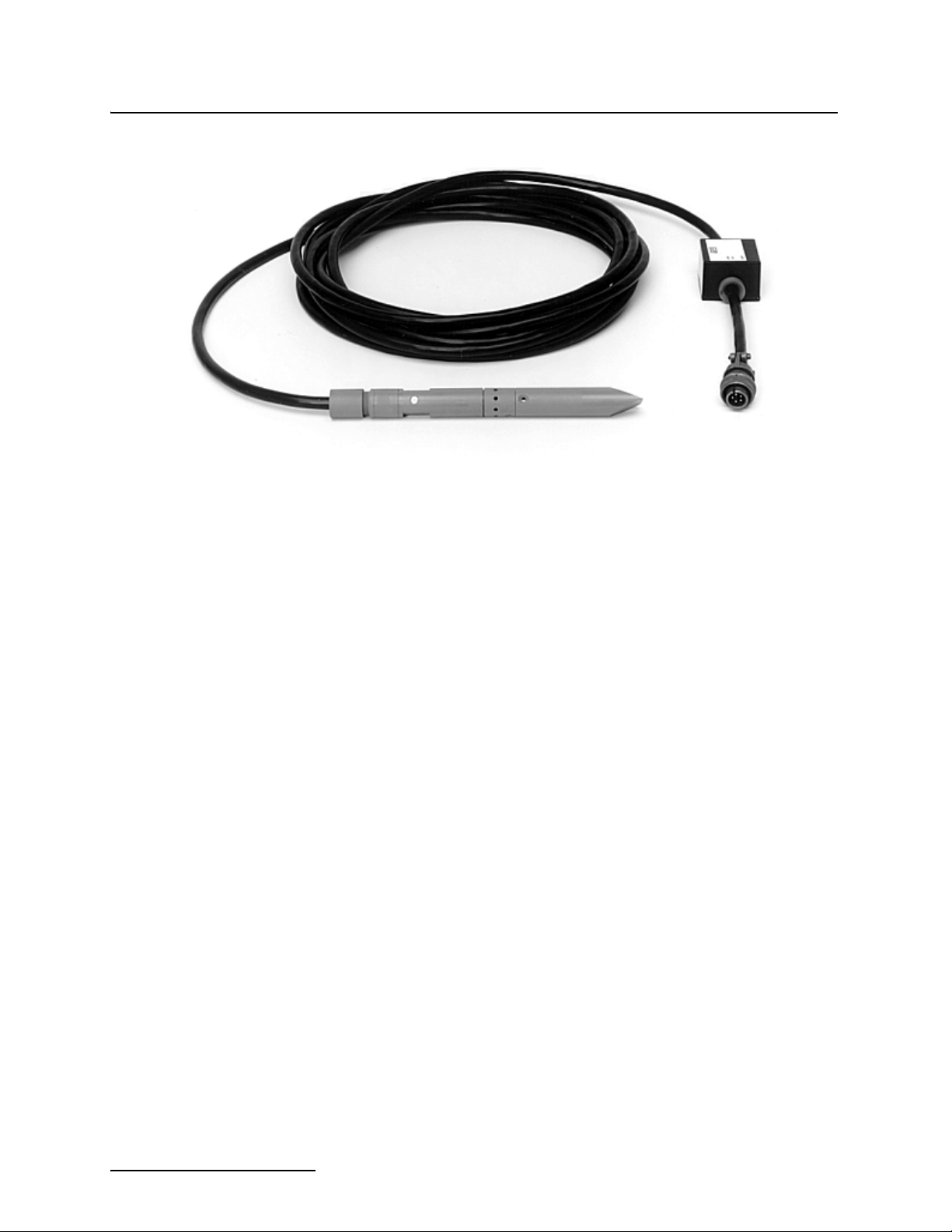
Figure 1-1 Submerged Probe Level Sensor with Standard Tip
1.3.3 Two Probes Available Teledyne Isco offers two different submerged probe level sensors
for use with the 4220. The standard unit is intended for operation in depths from 1 inch to 10 feet maximum. The other unit is
capable of operation to depths as great as 30 feet. The difference
in the probes is in the pressure transducer used inside. The two
are not interchangeable. You must select the appropriate unit
based on the maximum anticipated depth in your flow situation.
1.4 Software Upgrades Software for the 4200 Series Flow Meters can be upgraded
without the unit being returned to the factory. With Flash
Memory, software updates can easily be installed in the field
with a disk, a computer, and a cable. For more information about
installing software upgrades in the 4220 Flow Meter, see Section
6.
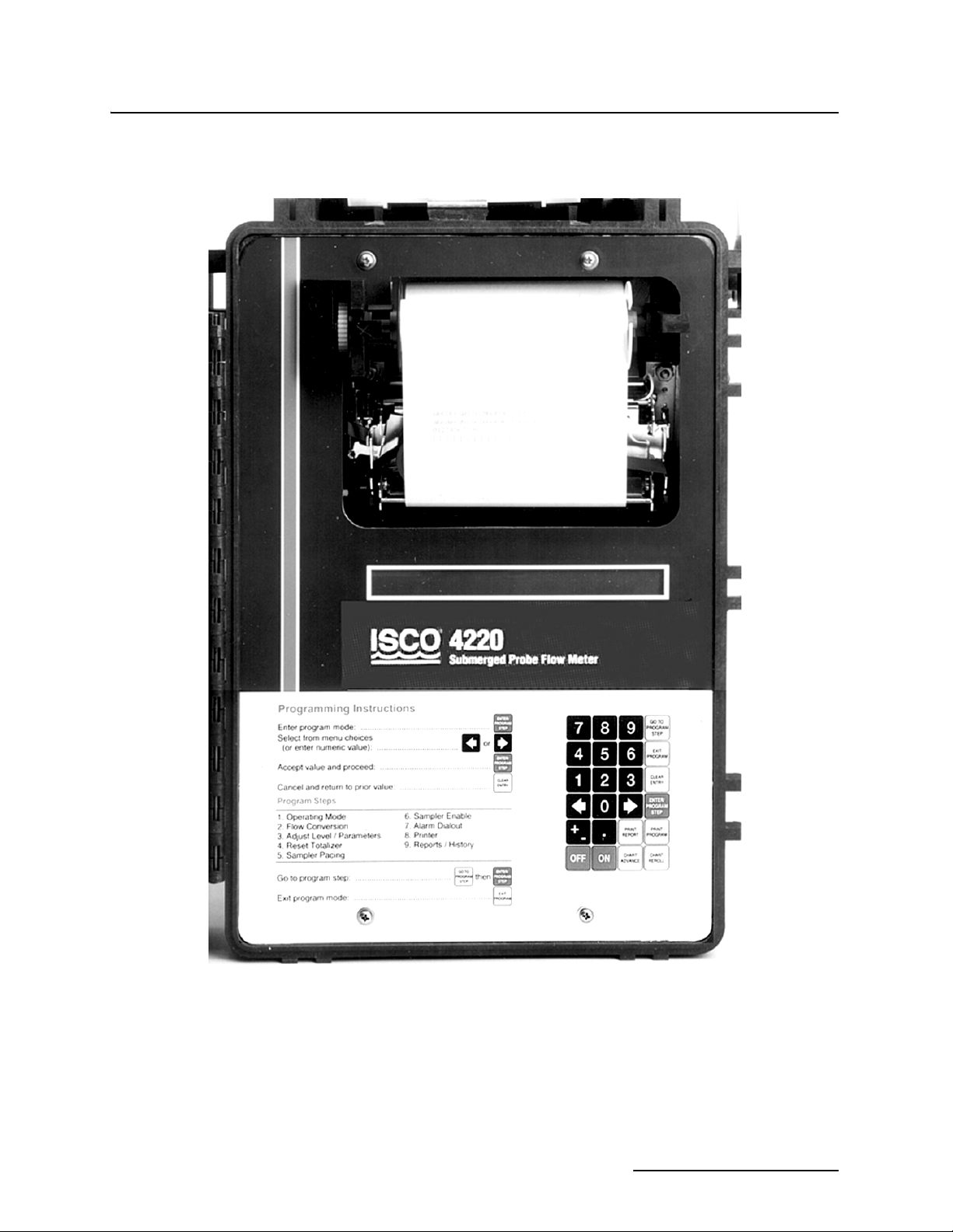
1.5 Controls, Indicators, and Connectors
The controls, indicators and connectors of the 4220 Flow Meter
are listed in Table 1-1, and their functions are briefly described.
Refer to Figure 1-2 for a view of the controls and indicators, and
Figure 1-3 for a view of the connectors and their pin functions.
1-4
Page 19
4220 Flow Meter
Section 1 Introduction
Figure 1-2 4220 Controls and Indicators
1-5
Page 20
4220 Flow Meter
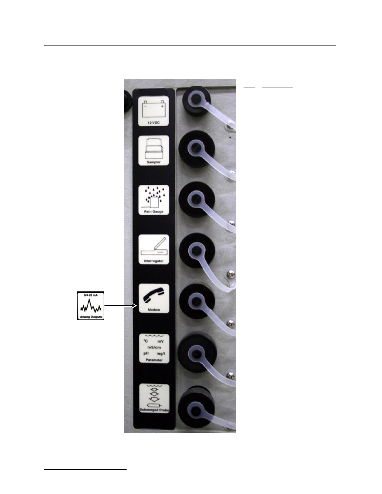
Section 1 Introduction
Pin Function
Power
Sampler
Rain Gauge
Interrogator
A Ground
B 12V
A 12V
B Ground
C Flow Pulse Output
D Bottle Number Input
E Event Mark Input
F Inhibit/Enable Output
A 12V
B Ground
C SDO
D Rain Gauge Input
A 12V
B Ground
C Sense Line
D SDO
E SDI
F Analog Output Pulse
Modem
(or Analog
Output)
A = Channel 1 (-) Red
B = Channel 3 (+) Green
C = Channel 1 (+) White
D = Channel 2 (-) Brown
E = Channel 3 (-) Black
F = Channel 2 (+) Blue
Parameter
Submerged
Probe
Figure 1-3 4220 Side View Showing Connectors and Pin
Functions
1-6
B Tip
C Ring
A 12V
B Ground
C Input Signal (+)
D Temp (-)
E Temp (+)
F Switched 12V
G Input Signal (-)
A 12V
B Ground
C Level (+)
D Level (-)
E Ground
Page 21

4220 Flow Meter
Section 1 Introduction
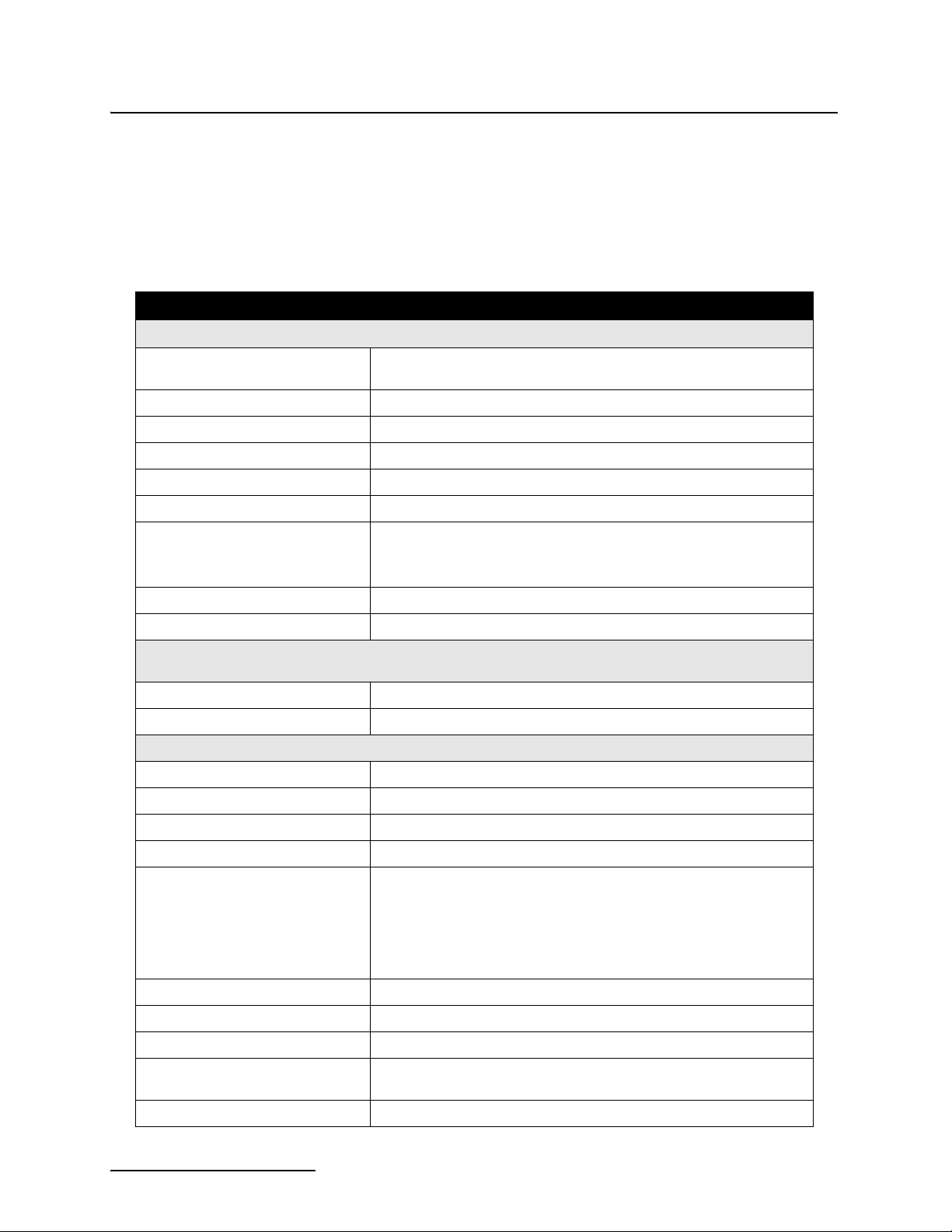
Table 1-1 Controls, Indicators, and Connectors
Controls Settings Function
ON/OFF On - Off Turns the flow meter on and off. Internal memory is protected with a
standby battery. See Section 2.
Keypad Momentary
Switches
24-key, four column matrix. Programs flow meter through a series of
keystrokes prompted by messages on the display. Certain keys perform specific functions (printing reports or entering program choices
into memory). Arrow keys move through menus. Number keys enter
numeric values. See Section 2.
Indicators Reading Function
Display Multi-function 2-line, 40 characters per line, liquid crystal display (LCD). Prompts
Internal Plotter Various Provides hard copy of total flow, level or flow rate variation over
you through program procedure; displays total flow, present flow
rate, and level. May also display parameter readings, if sensors
present.
time; provides sampling information and a printout of the program.
Prints reports. Generates three different linear data plots. Chart
characters and plots are generated on plain paper roll with an ink
ribbon.
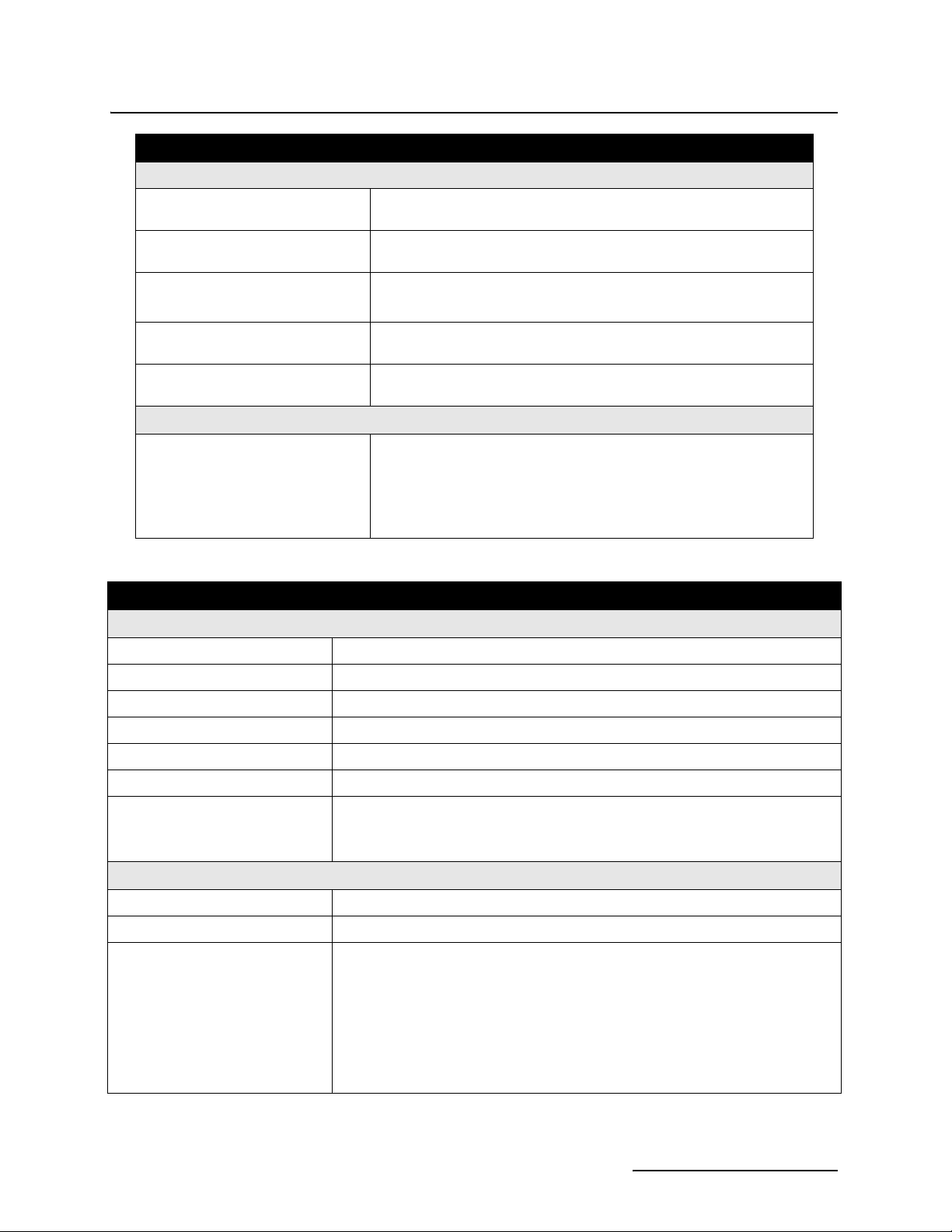
Connector Type Function
12 VDC 2-pin male M/S Connects 12 VDC power to flow meter.
Sampler 6-pin male M/S Connects flow meter to sampler; provides flow pulses to sampler;
receives sampler bottle number, composite sample, and event mark
signal.
Submerged Probe 5-pin, female M/S Connects submerged probe level sensor to flow meter. Also pro-
vides connection for reference port vent tube.
Rain Gauge/YSI 600
Sonde
9-pin Male M/S
(Custom)
Connects flow meter to an Isco 674 Rain Gauge or YSI 600
Multi-Parameter Sonde. Also provides output to High Low Alarm
Relay Box.
Interrogator 6-pin female M/S Provides serial data in/out and power. Can also be used with the
Modem (optional)
Analog Output
(optional)
Parameter 7-pin female M/S Connects flow meter to parameter sensor: temperature, pH, or D.O.
5-pin male M/S
6-pin male M/S
4-20 mA Output Interface and the 581 Rapid Transfer Device.
Connects flow meter to telephone line for remote data transmission.
This connector will only be present on units that have the optional
modem installed.
Provides analog data output from the flow meter to external,
non-Isco control and recording devices.
Note that you can only have temperature and one parameter (pH or
D.O.) at the same time.
NOTE: The 270 D.O. module is no longer available from Teledyne
Isco.
1-7
Page 22
4220 Flow Meter
Section 1 Introduction
1.6 Technical Specifications
The technical specifications for the 4220 Flow Meter are found in
Table 1-2. The anticipated longevity for a roll of paper used in the
internal plotter is shown for various chart speeds in Table 1-4.
Battery life expectancy is found in Table 1-5.
Table 1-2 Technical Specifications for the 4220 Flow Meter
Physical Specifications
1
Size 16" high × 11 1⁄2" wide × 10
power source attached).
Weight 17 lb. 4 oz. (7.7 kg)
Material High-impact molded polystyrene structural foam.
Type Self-certified NEMA 4X Enclosure.
Display Type 2-line, 40 character/line alphanumeric dot matrix liquid crystal.
Power 12 -14 VDC, 16 mA average at 12.5 VDC (Plotter set at 1" per hour).
Typical Battery Life 7-10 days with plotter at 1" per hour and 4 Ampere-hour Ni-Cad bat-
tery.
14 days with plotter turned off.
⁄2" deep (40.6 × 29.2 × 26.7 cm) (without
Operating Temperature 0° to 140°F (–18° to 60°C).
Storage Temperature –40° to 158°F (–40° to 70°C).
Additional Power Required
for Optional Equipment
Modem 60 mA maximum during operation; 0.1 mA maximum standby.
High-Low Alarm Relay Box 10 mA standby, typical; 190 mA - both relays operated.
Internal Printer
1
Chart Speeds Off,
Ribbon 19.7 ft. (6 m) black nylon - replaceable.
Operating Speed 1.5 lines per second at 68° F. (20° C).
Character Size 0.09" high × 0.07" wide (2.4mm × 1.7 mm), 12 pitch.
Printer Recording Span
Chart Resolution
Display Resolution
Paper 4.5" wide × 65 ft. (11.4 cm × 19.8 m) plain white paper, replaceable.
Printer Reliability 2.5 million lines MCBF (mean cycles before failure).
Reports Printed Program selections, interval activity reports, flow meter history.
⁄2, 1, 2, or 4 inches per hour.
User-selected from 1⁄4 ft. (3.6 cm) to over 30 ft. (9.1 m) with multiple
over-ranges.
1
⁄240 of selected recording span
0.001 ft. (0.3 mm)
Printer Recording Modes Level, flow rate; includes totalized flow, sampler events, rainfall, tem-
Plotted Linear Data 3 different linear plots can be printed at the same time.
perature, velocity, pH (or) D. O. (dissolved oxygen).
1-8
Page 23
4220 Flow Meter
Section 1 Introduction
Table 1-2 Technical Specifications for the 4220 Flow Meter (Continued)
Flowlink Data Storage and Retrieval System
Memory Partitions Maximum of 6 user-defined memory partitions for level or event stor-
age.
Data Storage Rate of data storage user-selected in 1, 2, 5, 10, 15, 30, 60, or 120
minute intervals.
Baud Rates Serial connection - 300, 1200, 2400, 4800, or 9600 baud.
Serial connection with the optional internal modem - 2400 baud.
Storage 80,000 bytes, apportioned per reading as follows: flow = 4 bytes,
Level Data Level readings are stored as a 16-bit number representing .1mm
level = 2 bytes, sample = 4 bytes, pH or D. O. = 1 byte)
(0.0394 inch); effective range is 0–65279 meters.
Flow Conversion
Flow Rate Calculations The flow meter creates a table of level-versus-flow rate from program
selections; this table divides the level span into 256 equally-spaced
level increments. Each level increment corresponds to a specific flow
rate. During data collection, if the measured level falls between two
table values, the flow meter will perform a linear interpolation to calculate the flow rate value.
Table 1-3 Technical Specifications for the 3222 Submerged Probe
Physical Specifications
Dimensions
Weight 3 lb, (including amplifier box and cable) (1.4 kg).
Body Material CPVC (chlorinated polyvinyl chloride) housing, stainless steel.
Cable Length 25 ft. (7.6 m).
Operating Temperature 32° to 160°F (0° to 71°C).
Storage Temperature –40° to 160°F (–40° to 71°C).
Maximum Distances
(between flow meter and level sensor)
7
⁄8” diameter × 91⁄2" long (2.2 × 24.1 cm).
75 feet (22.7 m) with optional extension cables.
1,000 feet (305 m) with optional Quick-Disconnect Box.
Level Measurement Specifications
Measurement Range 0.1 to 10.0 ft. (0.03 to 3.05 meters).
Maximum Level 20.0 ft. (6.1 m).
Measurement Accuracy Standard Sensor:
0.033 to 5.0 ft: ±0.008 ft/ft (0.01 to 1.52 m: ±0.008 m/m)
>5.0 ft: ±0.012 ft/ft (>1.52 m: ±0.012 m/m)
@ 77° F (25° C). Includes non-linearity, repeatability, and hysteresis, but does not
include temperature coefficient.
Specifications include nonlinearity, repeatability, and hysteresis, but do not
include a temperature coefficient.
1-9
Page 24
4220 Flow Meter
Section 1 Introduction
Table 1-3 Technical Specifications for the 3222 Submerged Probe (Continued)
Compensated Temperature Range 32° to 122°F (0° to 50° C).
Temperature Error (over compensated temperature range)
0.1 to 4.0 ft. (0.03 to 1.2 m) ±0.005 ft. per degree F
4.0 to 10.0 ft. (1.2 to 3.1 m) ±0.007 ft. per degree F
Table 1-4 Chart Longevity
Chart Speed, Inches/Hour Time to Empty Roll
1
/4 Days
1
/2 Days
1
/2 Days)
4 195 Hours (8
216
132
0.5 65 Days
Note: Times assume Report Generator is turned off.
Table 1-5 Battery Life Expectancy
Flow Meter Settings Minimum
Reading Interval 5 Minutes Continuous Continuous
Printer Off Off 4” per Hour
Report Generator Off Off Every Hour
Average Current 14 mA 9 mA 23 mA
Nickel-Cadmium
Lead-Acid
Notes:
1. These figures are approximations based on calculations; actual times for your flow meter may vary due to
factors of battery age, charge condition, operating temperatures, and component differences. “Minimum” settings are those providing the lowest average current draw. “Maximum” settings are those requiring the highest current
draw. Your program should draw somewhere between the two.
2. The default settings are the program entered at the factory. You can reset the flow meter to the default program at
any time by holding down the 1 and Clear Entry keys at the same time.
3. The nickel-cadmium battery has a capacity of 4.0 ampere-hours at 20° C.
4. The lead-acid battery has a capacity of 6.5 ampere-hours at 20° C.
Both batteries are assumed to be fully charged with at least 95% of rated capacity and in good condition. These calculations also assume a 5% safety factor at the end of discharge. Lead-acid batteries should never be completely
discharged.
5. All fractional times are rounded down, rather than up.
3
4
10.7 Days
17.4 Days 27 Days 10.5 days
5
Default
16.6 Days 6.5 Days
2
1
Maximum
1.7 How to Make Battery Calculations
1-10
To calculate battery life expectancy for an installation, you must
know two things:
•The capacity of the battery you are using
•The average current draw of the flow meter or (other
device) powered.
Page 25

4220 Flow Meter
Section 1 Introduction
Battery capacity is expressed in ampere-hours. The battery
manufacturer provides this information for each battery. This
value is the product of a load current times an arbitrary time
period, ten hours for nickel-cadmium batteries, and twenty hours
for lead-acid types. The terminal voltage of the battery at the end
of this time period is the discharged cell voltage, 10 volts for
nickel-cadmium and 10.5 volts for lead-acid types. Note that batteries are fully discharged well before the terminal voltage drops
to zero volts.
Isco batteries are rated at 4 ampere-hours for the
nickel-cadmium and 6.5 ampere-hours for lead-acid types.
Convert the battery current capacity into milliamperes and then
divide this figure by the average current drawn by the unit. This
will give you a number in hours. Divide that figure by 24, and
you will have the number of days.
Note that the published ampere-hour figures do not mean that
you can expect to draw 4 amperes from the nickel-cadmium
battery (or 6.5 amperes from the lead-acid battery) for one hour.
At the one-hour rate, discharges are typically less than half the
ten- or twenty-hour rate.
To convert ampere-hours to milliamperes, multiply by 1,000.
Examples:
4 ampere-hours × 1,000 = 4,000 mAh.
6.5 ampere-hours × 1,000 = 6,500 mAh.
If you divide this figure by the average current of the flow meter,
say 15 mA, you will have:
4,000 ÷ 15 = 266.67 hours.
Divide this number by twenty-four to get days:
266.67 hours ÷ 24 = 11.1 days.
As a margin of safety, we suggest you subtract 10% from this
number (100% – 5% for 95% capacity and 5% for a reserve at the
end of discharge).
11.1 – 1.1 = 10 days
This is the battery expectancy for a nickel-cadmium battery with
a 15 mA continuous average drain, with a 10% derating factor.
You can use the same method to calculate for lead-acid batteries,
except the current will be 6,500 mA, and the period correspondingly longer, in this case a little over 16 days. You can run the full
number of days calculated without derating if your batteries are
new and at 100% capacity, but you will leave yourself no safety
factor if you are in error on either of these assumptions.
Remember, if the battery fails, there will be a period of time
during which no measurements will be taken, (and no data
stored, if you are also using Flowlink® software).
Batteries lose capacity as they age. Capacity also drops off as
temperature falls. Low temperatures make less capacity
available due to the slowing of the chemical reactions, while high
temperatures accelerate the deterioration of battery plate separators, particularly if they are aged. Note also that
1-11
Page 26

4220 Flow Meter
Section 1 Introduction
nickel-cadmium batteries show fairly rapid rates of self-discharge. A battery that is fully charged and then placed in storage
will lose some capacity each day. In a week, this could easily be
5% or more.
When using lead-acid batteries, you must be careful to avoid
complete discharge, as this may cause cell reversal, which will
ruin the battery. Also, complete discharge in low temperature
ambients may cause the battery to freeze, which can deform the
plates or even crack the case. Always operate these batteries
with a reserve factor!
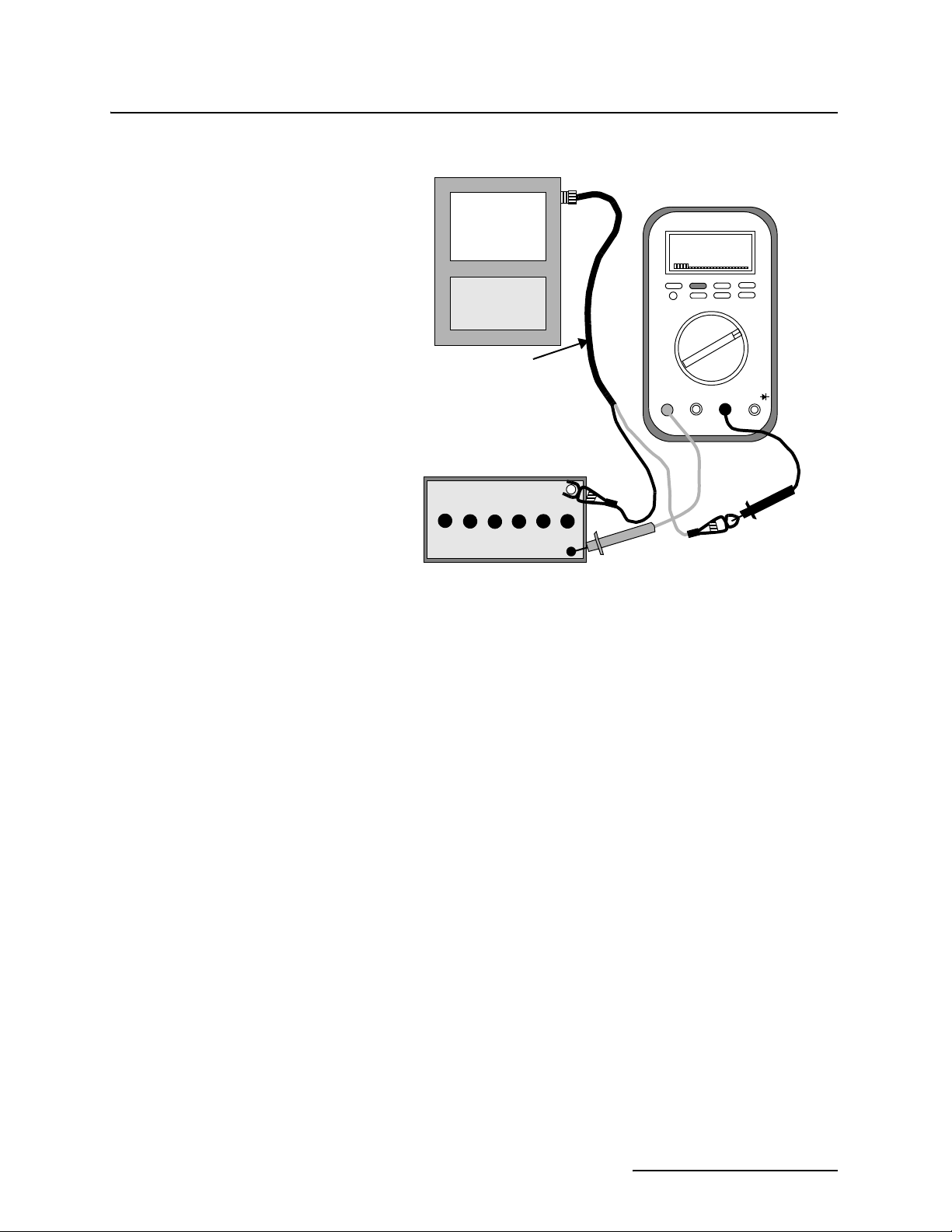
1.7.1 Current Draw Calculating current draw for a 4220 Flow Meter is somewhat more difficult than calculating the battery capacity. You cannot simply measure the idle current of the unit unless the printer and report generator are turned off in the program. These functions require power periodically, but not all the time. If the figures given in the previous table are not satisfactory for your application, you can use the following procedure (shown in Figure 1-4) to measure the actual current draw.
Note
Do not attempt this procedure unless you have the proper
equipment available and know how to make electrical measurements.
To measure current for a varying load requires a more-sophisticated type of multimeter, one that is capable of averaging high
and low readings over a period of time. You should set the meter
on MIN/MAX and let it run with your program for several hours
or more. Other manufacturers’ meters are also acceptable, but
only if they are capable of averaging current draw. For a more
representative test, the area-velocity sensor should be attached
and submerged in water. You should run the test for at least
eight hours, longer if necessary, or until the flow meter has
exercised the entire program. The longer you run the test, the
more accurate the average will be.
1-12
Page 27
4220 Flow Meter
Section 1 Introduction
Fluke® 87
(or other current-
averaging meter)
FLUKE 87 TRUE RMS MULTIMETER
00I5
Flow
Meter
Connect Cable
60-1394-023,
or you can make
your own.
Battery, 12 Volt
A
mA μA
–
Com
+ lead
mA
V Ω
A
Figure 1-4 Measuring the Flow Meter Current
Additional information about batteries used to power Isco
equipment is available from the Isco Power Products Guide,
which is shipped with this manual and any flow meter order.
+
+ clip
A good quality, adjustable, regulated DC power supply
can be substituted for the 12-volt battery. The power
supply should have at least 3 Amperes output, preferably more, and capable of overcurrent surges.
1-13
Page 28

4220 Flow Meter
Section 1 Introduction
1-14
Page 29

4220 Flow Meter
Section 2 Programming
2.1 Getting Started You must program the 4220 Flow Meter to accurately monitor a
flow stream. You must also install the submerged probe level
sensor. The 4220 will usually also need a primary measuring
device, a structure placed across a stream that regulates flow.
This section describes programming the flow meter with the aid
of the keypad and display. There are nine program steps that
control all aspects of the flow meter's operation.
Teledyne Isco ships the flow meter with a program already
installed that is called the default program. You can use this
program as an example to see the flow meter's capabilities. Note
that the default program is just to test the unit at the factory.
The flow meter's internal computer must always have something
programmed into the unit, so that becomes the default program.
Your flow situation will usually require other programming
choices. The text provided with each screen explains the reasons
for the various menu options.
2.1.1 Operation of the
Display
The display is a two-line, forty character-per-line liquid crystal
(LCD). It has a backlight feature for easy viewing in low light situations. The display has three different operating modes:
normal, programming, and messages. In the normal mode,
the display shows such things as level, flow rate, total flow,
parameter measurement, etc. In the programming mode, the
top line of the display shows each step as you work through the
program while the bottom line shows the choices available for
that step. In the message mode, the display provides instructional information, such as how to leave programming, or what to
do if you have entered a number that is out-of-range.
Following is a “normal” display on the flow meter. This is typical
of what the flow meter will display when it is in the normal operating mode and you are not programming it.
0000004.78 CF 1.13 FT 16-NOV-02
1.03 CFS (X X) 8:25:37
An interpretation of the numbers on this display would be as
follows: Time and date will be replaced by pH/D.O. and temperature if you are using parameter sensing. The (X X) to the right
of the time indicates letters that may appear from time to time
on the 4220 Flow Meter.
The letter C will appear when the flow meter is communicating
with a remote computer (Flowlink applications only). The letters
E or D will appear (Enable or Disable) when the sampler enable
function (step 6) is programmed by condition. (Programmed by
2-1
Page 30

4220 Flow Meter
Section 2 Programming
condition means that the flow meter will enable the sampler only
when a certain condition or set of conditions, sensed by the flow
meter, are met.)
Total Flow Current Level Date (or pH/D.O.)
Flow Rate Time (temperature)
Following is a typical programming display on the flow meter.
One of the items in the second line will be flashing. The item
flashing is the selection currently held in memory.
TOTALIZED VOLUME UNITS
• CF • • GAL • • M3 • • AF • • L • • MGAL •
Following is a typical display providing instructional information:
CHANGES HAVE BEEN MADE IN STEP
PRESS '0' TO CONTINUE, PRESS '1' TO DISCARD
If you stop programming for more than two minutes, the flow
meter will time out, and whatever is on the display (message or
program step) will revert to the “normal” display, shown previously.
The program consists of steps and substeps. The steps are listed
on the flow meter front panel. Most steps contain several substeps. Generally, you need to complete all the substeps before
stopping, or the flow meter will reject the changes you made for
that step after it times out. There are some exceptions.
The flow meter keeps in memory any changes that you made for
the finished steps (all substeps completed before stopping). Most
steps not finished when you stop will return to the previous
selection.
2.1.2 Keypad Functions Programming is done on the flow meter's keypad with prompts from the display. The following sections describe the function of each key.
OFF and ON - These two keys turn the flow meter off and on.
Go To Program Step - Pressing this key lets you go directly to a
particular program step without passing through all the steps of
the entire program. The display will ask you to enter the number
of the step you want to program. Enter the number by pressing
one of the number keys. There are nine program steps, so
numbers from one to nine are valid.
Exit Program - Press this key when you want to leave the programming mode and return to the normal operating mode.
Clear Entry - This key lets you return to the previous entry for
a program step if you have changed the entry, but not yet pressed
Enter.
Enter/Program Step - This key has two functions. One is to
enter a program selection into the flow meter's memory (Enter).
The other is to step through the program (Program Step).
2-2
Page 31

4220 Flow Meter
Section 2 Programming
Print Program - Pressing this key will make the flow meter
print out a complete list of the current program choices retained
in memory.
Print Report - One function of the flow meter is to print reports
of all recorded activity at regular intervals. The contents of these
reports are defined in step 1. If you set up the report generator,
you can have a report printed anytime by pressing this key. The
report will cover the time from the last scheduled report up to
when you press this key.
The flow meter will print its next report at the next scheduled
time. Note that if power fails for five minutes or more, the flow
meter will print a report when power is restored that will cover
the interval between the last report and the time that the power
failed. The next report will cover the time from the power failure
to next scheduled report time.
Chart Advance - Pressing this key causes the paper chart to
advance through the printer at the fastest possible speed.
Nothing will be printed while you are holding this key.
Chart Reroll - It is possible to unroll the chart from the take-up
roll on the flow meter by pulling it out with your hands. Pressing
this key lets you rewind the chart onto the take-up roll.
Number keys - These keys let you enter numeric values into the
flow meter when programming.
Decimal Point - This key lets you enter a decimal point into a
numeric value when programming. On flow meters equipped
with the optional modem only, you can use this character as a
comma (delay) when entering dialout numbers.
Arrow keys - These keys, referred to as the left and right
arrow keys let you select a programming option by moving
across the menus shown on the second line of the display.
+/– key - This key lets you enter a plus or minus to a quantity
entered. Its most common use is in entering values for the
equation, a method of flow conversion. On flow meters equipped
with the optional modem only, you can use this character as a
dash when entering dialout numbers.
2.2 Programming Procedure
To start programming, turn on the flow meter and wait for the
display to settle. Then either press the Enter/Program Step
key (generally referred to as Enter) or the Go To Program
Step key.
The display will change to two lines of text; the first line
describes the step you are programming and the second line
shows the choices available. One choice shown will be flashing.
The flashing indicates that this is the current one held in the
memory. If you are satisfied with this choice, just press Enter,
and the flow meter will advance to the next step.
2-3
Page 32

4220 Flow Meter
Section 2 Programming
If you want a different choice from the one that is flashing, you
can move across the display by using the left and right arrow
keys. Each time you press the right arrow key, the flashing
selection will move one position to the right. This will continue
until the flashing cursor is over the last display.
You may notice an arrow pointing to the edge of the display. This
indicates additional choices are available beyond what you can
see. By continuing to press the right arrow key you can view
these unseen menu options. After reaching the furthest option,
the arrow will move to the left side of the display, indicating that
there are options unseen to the left. These will be the options you
started with. If you want to go back to one of them, use the left
arrow key until the option you need reappears. When the
desired selection is flashing, just press Enter. The display will
then automatically advance to the next step of the program.
All of the program steps contain “substeps” that must be completed before you advance to the next step. Some steps, like
Reset Totalizer contain only a few substeps. Some steps require
the entry of a numeric value. Program these steps by using the
number and decimal keys to enter the value.
Note that it is possible to program the flow meter in the shop,
rather than at the job site, with the exception of step 3, Adjust
Level/Parameters. To set level you must make an accurate measurement of the level in the flow stream and then enter that
value. This can only be done at the job site.
If you are programming the flow meter for the first time, generally you will press Enter, start with step 1, and go on from
there. If the flow meter has been in use and you need to change
only certain aspects of the program, you would more likely use
the Go To Program Step key. With this key you can go directly
to the program step you need to change, which saves time.
If you change an entry and do not like it you can make the
display revert to the original entry by pressing Clear Entry. If
you have already pressed Enter, however, the new value will be
in memory. To change it, press Exit Program. If you are in the
middle of a program step with multiple substeps, the flow meter
will display, “Changes have been made in step; press 0 to continue or 1 to discard.” If you press 1, the display will return to
normal and the last step you were working on will revert to its
previous selection. (Any program step you completely change
before exiting will remain changed.)
You can re-enter the program with either Enter or the Go To
Program Step keys. If you become confused while programming, the best suggestion is to press Exit Program and
start over. Also remember that you can have the flow meter print
a complete list of your program choices by exiting the program
and by pressing the Print Program key as soon as the display
returns to the normal operating condition, displaying level and
total flow, etc.
2-4
Page 33

4220 Flow Meter
Section 2 Programming
2.3 Description of Program Steps
2.3.1 Step 1, Operating Mode
The Program Steps for the 4220 are:
1. Operating Mode
2. Flow Conversion
3. Adjust Level/Parameters
4. Reset Totalizer
5. Sampler Pacing
6. Sampler Enable
7. Alarm Dialout
8. Printer
9. Reports/History
Note
If you choose NOT MEASURED for any selection, the flow
meter will make no further reference to that value or function
for the rest of the program, and you will not be able to activate
that process or function later on unless you reprogram step 1.
If there is a feature or option you need that does not appear on
your display when the manual says it should, return to step 1
and make sure you have not inadvertently left it turned off in
either the Program or Setup menus.
Note that selecting some features automatically excludes others. For example, selection of pH or D. O. excludes the other
parameter, unless you use the YSI 600 Multi-Parameter
Sonde, which measures pH, D.O., and conductivity at the
same time.
Step 1, Operating Mode, determines how you set up the flow
meter. In this step there are two choices, Program and Setup.
Program advances you to step 2, and from there on you correlate the flow meter to the flow stream. Setup selects various
basic “housekeeping” features for the flow meter. Here you
determine the internal clock, site identification, measurement
setup, hysteresis, report contents, operation of the display backlight, and program lock. In Program you select the units of
measure the flow meter will use for the display, calculations, and
reports.
This method keeps program size manageable and makes programming more efficient. By turning off unneeded features of the
program early, you do not have to keep de-selecting those features over and over as you work through the program.
Consequently, you should choose carefully from the first step. We
suggest you study the program first, then fill out the Pro-
gramming Worksheets (in the back of this manual), and program
the flow meter last, if you are unfamiliar with the unit.
2-5
Page 34

4220 Flow Meter
Section 2 Programming
2.3.2 Step 2, Flow Conversion Type
Step 2, Flow Conversion Type, determines how the flow meter
calculates flow rate and total flow. For the 4220 Flow Meter, flow
rate is calculated by knowing the measured level and (usually)
the characteristics of a structure called a primary measuring
device.
A primary measuring device is a structure placed across a flow
stream through which the entire stream must flow. These devices
are made in a number of styles and sizes, but they all have one
thing in common: For any type of primary measuring device
there is a known relationship between the level in the flow
stream ahead of the device and flow rate through the device.
Consequently, after you measure level with the flow meter, it can
calculate flow rate and total flow from the measured level, by
consulting built-in look-up tables.
Detailed information about many commonly-used primary measuring devices is provided in the Isco Open Channel Flow Mea-
surement Handbook. This useful book provides formulas, flow
rates at various levels, and values for maximum head, as well as
much interesting descriptive material, and is available from
Teledyne Isco. If your installation uses a nonstandard primary
device, you should consult the manufacturer of the device for flow
rates at given levels. The flow meter will then calculate a flow
conversion for such a device on the basis of the manufacturers'
data you enter as data points or an equation. In some
instances, a nonstandard primary device could be supplied with a
flow equation; you can enter that equation into the flow meter
and the flow meter will calculate the flow rate from that
equation.
Note however, that it is not always necessary to have a primary
measuring device. The 4220 Flow Meters can measure level and
calculate flow without having any primary device installed in the
flow stream. Sometimes the shape of the flow stream itself forms
the primary device.
The Manning formula uses the shape of a pipe or channel and
its slope to calculate flow in open (non-pressurized) pipe situations.
The conversion types available are WEIR/FLUME, MANNING,
DATA POINTS, and EQUATION.
You us e Weir/Flume flow conversion when your primary measuring device is a weir or a flume. A weir is a wall or dam across
the flow stream. Water must rise to the point where it flows over
the top of the wall. The measured level upstream behind the wall
is used to calculate the flow rate. Flumes differ from weirs in
that there is no wall or barrier, but instead a restriction, typically
a sharp narrowing or change in the slope of the channel that
restricts the flow. Again, the measured level of the stream at
some point ahead of the restriction is used by the flow meter to
calculate flow. In this flow conversion mode, the flow meter uses
internal look-up tables for many common primary measuring
devices.
2-6
Page 35

4220 Flow Meter
Section 2 Programming
An Equation is used when you have a non-standard primary
device, or want to use different values from those programmed
into the look-up tables of the flow meter. Equation uses the
standard flow equation:
Q = k1H
Where Q equals flow rate; k1 and k2 are constants; H is level (or
head), and P1 and P2 are the powers to which the two H terms
are raised. (Your equation may not have the second term, in
which case you would enter 0 for the second constant, k2.) Most
common primary devices are supported in the flow meter's
software, so generally you will not need this option. But it is
available for those needing to enter their own values, or for those
who have a nonstandard primary device for which an equation
can correlate level and flow.
MANNING Flow Conversion uses the Manning formula to calculate flow in open or closed (non pressurized) gravity-flow situations based on slope, diameter, and roughness of the pipe. The
Manning formula is named for its developer, Robert Manning, a
19th-century Irish civil engineer. There is no primary measuring
device as such. Instead the pipe, with considerations for its slope
and internal roughness, serves as the primary device. The 4220
Flow Meter can calculate flow in round pipes, rectangular,
U-shaped, or trapezoidal channels based on this formula.
Data Point Flow Conversion (DATA POINTS) calculates flow
based on a set of user-entered data points for a flow stream. Data
consist of correlated level and flow measurements for the stream.
Like the Equation method of flow conversion, this flow conversion is most commonly used where the primary measuring
device is nonstandard, but where tables of level and flow rate
data are available from the device manufacturer. The 4220 Flow
Meter has space for four sets of data with as many as fifty points
per set. The flow meter then calculates flow from these data
tables using a three-point interpolation.
P1
+ k2H
P2
2.3.3 Step 3 - Adjust Level, Parameters
Adjust Level, Parameters calibrates the measuring sensors
that provide the flow meter with level and other information. In
this step you set the level that the flow meter measures. First
you measure, as accurately as possible, the level in the flow
stream. Then you enter this value with the numeric keys.
Accuracy is important. Remember that measured level provides
the basis for calculated flow in the flow meter.
The flow meter also has an input port for measurements other
than level. This is the Parameter Port. Here you can sense
such variables in the flow stream as temperature, pH (the acidity
or alkalinity of a solution) and D.O. (dissolved oxygen) in the flow
stream. You can have either pH with temperature, D.O. with
temperature, or temperature alone.
Note
The 270 D.O. module is no longer available from Teledyne
Isco.
2-7
Page 36

4220 Flow Meter
Section 2 Programming
The port is not dedicated to a particular sensor, except through
programming. You can change the sensor. For example, you can
change from a pH probe to a D.O. sensor if you change the programming. Selection of one parameter will keep the other from
showing up on the menus. Note, however, that it is possible to
measure several different stream conditions including pH and
D.O. at the same time with the YSI 600 Sonde.
The YSI 600 Sonde
The YSI 600 Sonde is a multi-purpose water quality measurement device. It is intended for use in research, assessment,
and regulatory compliance. The sonde attaches to the modified
RAIN GAUGE connector on the 4220. Flow meters having only a
4-pin rain gauge connector will not support the YSI Sonde. If you
wish to upgrade your flow meter to use this system, contact the
factory. Note that you can have both the YSI 600 Sonde and the
Rain Gauge connected to the flow meter at the same time by
using a special Y-connect cable.
The YSI 600 Sonde can measure the following water qualities:
dissolved oxygen (D.O.), conductivity, temperature, and
pH. Conductivity measurements made by the sonde can be used
to calculate specific conductivity, salinity, and total dissolved
solids. A brief description and specifications for the YSI 600 are
printed in Section 5. You may also contact the factory or your
Teledyne Isco representative. More information on the sonde is
found in the YSI 600 Manual, shipped with each YSI 600 Sonde.
Assembled Sonde
Conductivity (inside)
(Cover Removed)
pH glass sensor
Tem pera ture
pH reference
D.O. se nso r
Figure 2-1 The YSI 600 Sonde
2.3.4 Step 4 - Reset Totalizer In this step, you decide whether to reset the flow meter's internal
flow totalizers. If the installation is permanent, you generally
won't reset the totalizer. If you are using the flow meter as a portable recording unit and move it from site to site, you would generally reset the totalizer between sites.
2.3.5 Step 5 - Sampler Pacing
It is common to use a flow meter with an Isco Automatic Wastewater Sampler. Typically the flow meter signals the sampler to
take a sample after a certain volume has passed. It might also
occur after a certain condition or set of conditions has either
changed or been met. This step allows you to determine that
2-8
Page 37

4220 Flow Meter
Section 2 Programming
control. There are several possible options—DISABLE, CONDITIONAL, VOLUME, and FLOWLINK. DISABLE will keep the
sampler from receiving a flow pulse from the flow meter.
VOLUME allows the flow meter to signal the sampler whenever
a specific flow volume has passed by. Flowlink (this option will
only appear if you are using Flowlink software) allows the
sampler to be signalled from the flow meter as a result of conditions determined by Flowlink.
Flowlink is Isco's proprietary data acquisition and management
software. Flowlink works with personal computers, modems, and
laptop computers to monitor flow meters from a distance.
Consult the factory for more details about Flowlink.
VOLUME makes the flow meter pace the sampler after a specific volume passes through the stream.
CONDITIONAL allows pacing of the sampler by the flow meter
when a particular condition has been met, or has changed.
Among these conditions are changes in level, flow rate, temperature, rainfall, (if you are using the optional rain gauge sensor),
D.O. (dissolved oxygen), or pH. You can also use a pair of conditions, or if you are using the YSI 600 sonde, you can select multiple conditions from its sensors.
2.3.6 Step 6 - Sampler Enable
Note
If you choose CONDITIONAL for sampler pacing and it doesn’t
seem to work properly for you, read the section on hysteresis.
Then check the hysteresis setpoints for your conditions. (The
defaults are all zero.)
You must have the appropriate sensors attached to the flow
meter to measure temperature, D.O., pH, conductivity, etc.; the
flow meter cannot do this by itself, nor does it occur automatically.
Sampler Enable means that in a combination flow
meter/sampler pair, the flow meter controls the sampler's ability
to run its own program. The difference between step 5, sampler
pacing, and step 6, sampler enable is that in sampler pacing, the
flow meter merely sends flow pulses to the sampler from time to
time. The sampler counts these flow pulses to determine when to
take a sample (according to its own programming).
With sampler pacing, the sampler is always enabled. With
sampler enabling, the flow meter can actually stop operation of
the sampler. The sampler is still set up to run its own program,
but the inhibit/enable line from the flow meter will determine
when and whether the sampler runs its program. This feature is
useful for storm water runoff monitoring applications, where it
may be necessary for the flow meter/sampler pair to have to wait
a long time between storm intervals.
Again, changing or meeting a condition or set of conditions
triggers the enabling. The conditions that can be used for
sampler enabling are similar to those used for sampler pacing:
level, flow rate, rainfall, temperature, dissolved oxygen, pH, or a
2-9
Page 38

4220 Flow Meter
Section 2 Programming
2.3.7 Step 7 - Alarm Dialout Mode
combination of these conditions. The YSI 600 Sonde provides
several measurements at the same time. You must have the
appropriate sensors for rainfall, temperature, D. O., pH and the
YSI outputs.
Note
You must have the optional modem to make use of this program step. The menus will not even appear unless the flow
meter has a modem installed.
This feature allows you to program a 4200 Series Flow Meter to
signal a remote location through a telephone line. The Alarm
Dialout feature is useful if you need to signal a remote location
when there is a change of condition in the flow stream that could
constitute an alarm. You can program as many as five different
eighteen-digit telephone numbers into the flow meter in
decreasing order of importance. The modem is capable of speech.
DISABLE inhibits this function altogether. CONDITIONAL
lets you program the flow meter to signal these alarms for a
variety of reasons. You can use rainfall, time, level, flow rate, dissolved oxygen, pH, rate-of-change, a combination of conditions,
or define the operation through Flowlink software from another
computer. STORM lets you set the alarm through a combination
of rainfall and time. You can also program the interval between
calls and set up the system to reset the alarm condition by
dialing back from the remote telephone.
2.3.8 Step 8 - Printer All 4220 Flow Meters have a built-in printer. The printer is more
than just a printer, as it is capable of plotting linear data along
2.3.9 Step 9 Reports/History
with printing alphanumeric (letters and numbers) messages. In
this step you set the speed for the chart to advance, from
4" per hour. Chart speed is set according to the amount of resolution you want to see on the chart. If there is much activity on
the chart, you would generally choose a faster speed so the marks
are more “spread out” and are easier to interpret. If there is little
activity on the chart and you want the flow meter to run for long
periods without having to change the chart paper roll, you would
probably pick a slower speed.
The flow meter is capable of plotting three separate data lines on
the chart in addition to the alphanumeric messages. These lines
may indicate various things, such as level, flow rate, pH, dissolved oxygen, or temperature. Note that you must have the
appropriate sensors for pH, DO, and temperature to make use of
these plots. Rainfall is printed as a bar-graph. The printer is
capable of plotting over-ranges for the data lines it plots. You can
tell when the printer is in over-range if a data line goes off the
chart on the right side and then immediately starts over again
plotting on the left side.
This step lets you program the flow meter to print out regular
reports on the internal printer. The reports the flow meter prints
are a summary of activity the unit records over a period of time.
1
/2" to
2-10
Page 39

4220 Flow Meter
Section 2 Programming
Typically included are such items as maximum and minimum
flow rates, the time they were reached, sample records, etc. The
flow meter lets you create two separate reports, and lets you
define what appears on them to a great extent. Note that the contents of the reports are defined in Setup in step 1. Step 9 merely
lets you turn them off and on and set the timing. You can define
the start time, the interval between reports and other aspects of
the report.
History provides a record of changes made to the flow meter's
program or operation events. As many as 50 changes can be
stored in the flow meter's memory at a time. The memory can
store up to 50 history items and 200 sample events at a time.
2.4 Interpreting the Program Screens
Following are the program screens as they appear on the display
of a 4220 Flow Meter. Explanations of most of the screens will be
provided.
Note
Some items that appear in the menus have parentheses (...)
around them. This means that the item may or may not appear
on your flow meter. Choices made from the beginning of the
program will make some options unavailable later.
An example of this is the pH/D.O. option. Selection of one in
Step 1 will keep the other from appearing in all following
menus.
This list does not include all possible screens for the unit, but
does cover the screens found in a typical programming
sequence. Some diagnostic and error screens are covered in
Section 6.
2.4.1 Operating Mode Turn on the machine. Wait for the display to settle. Then press the Enter/Program Step (Enter) key. The following will appear. (Step 1) If the following menu does not appear, press Exit Program, then Go To Program Step, then press 1.
SELECT OPTION
• PROGRAM • • SETUP •
PROGRAM is always the default. If you press Enter, the display
will automatically advance to the next display, which will ask
you to select units of measurement. If you select SETUP, the following will appear:
SETUP OPTIONS: 'EXIT' TO QUIT
• SET CLOCK • • SITE ID • • MEASUREMENT SETUP •
If you press the right arrow key, the following options will
appear in this order on the display:
SETUP OPTIONS: 'EXIT' TO QUIT
• STATUS ENABLE/ALARM HYSTERESIS •
2-11
Page 40

4220 Flow Meter
Section 2 Programming
SETUP OPTIONS: 'EXIT' TO QUIT
• OPTIONAL OUTPUTS • • REPORT SETUP •
SETUP OPTIONS: 'EXIT' TO QUIT
• LCD BACKLIGHT • • (LANGUAGE) • • PROGRAM LOCK •
SETUP OPTIONS: 'EXIT' TO QUIT
• (LANGUAGE) • • PROGRAM LOCK • • PROGRAM •
LANGUAGE may not appear on your machine. This is intended
primarily for export models, as they are programmed in different
languages. Domestic models contain only English.
If you select SET CLOCK, the following will appear:
YEAR MONTH DAY HOUR MIN
XXXX XX XX XX XX
Enter the year (four digits), the month (01-12), the day (01-31),
the hour (01-24), and the minute (01-59).
If you select SITE ID, the following will appear:
SITE ID: XXX
You can select any suitable three-digit number for the site identification.
If you select MEASUREMENT SETUP, the following will appear.
You will have to use the right arrow key to bring all the options
on screen:
MEASUREMENT SETUP
• LEVEL READING INTERVAL • • DO/PH READING INT-,
MEASUREMENT SETUP
• DO/PH READING INTERVAL • •YSI 600 READING INT-
-ERVAL is just off the screen. LEVEL READING INTERVAL
refers to how often the flow meter takes a level reading. LEVEL
refers to the level in the flow stream.
DO/PH READING INTERVAL refers to the measurement of specific aspects of the flow stream other than amount. 4220 Flow
Meters support measurement of three different characteristics:
temperature, pH (the relative acidity or alkalinity of a solution),
and D.O., dissolved oxygen.
2-12
Note
If you are using the Isco D.O. sensor or are sensing D.O. with
the YSI 600 Sonde, select as long a measurement interval as
is practical for your application. The reasoning is that the D.O.
sensor is turned off between measurement intervals and this
turned-off period prolongs the life of the sensor.
Page 41

4220 Flow Meter
Section 2 Programming
YSI 600 READING INTERVAL refers to the YSI 600 Sonde. The
flow meter can measure several different aspects of the stream at
the same time, including pH, D.O., temperature, plus conductivity.
If you select LEVEL READING INTERVAL, the following will
appear:
LEVEL READING INTERVAL
• CONTINUOUS • • 15 SEC • • 30 SEC • • 1 MIN • • 2 MIN • • 5 MIN •
The LEVEL READING INTERVAL option is a way to conserve
power in battery-powered installations. If your installation is
AC-powered, you can simply select CONTINUOUS.
If you select DO/PH READING INTERVAL, the following will
appear:
DO/PH READING INTERVAL
• CONTINUOUS • • 15 SEC • • 30 SEC • • 1 MIN • • 2 MIN • • 5 MIN •
Again, this selection is offered as a means of saving battery
power. After selecting the appropriate parameter reading
interval, press Enter. The Setup menu will reappear. This time,
select YSI 600 READING INTERVAL from the menu. The following display will appear:
YSI 600 READING INTERVAL
•CONTINUOUS••15 SEC••30 SEC••1 MIN••2 MIN••5 MIN•
After selecting the appropriate parameter reading interval, press
Enter. The Setup menu will reappear. This time select STATUS
from the Setup menu. Press Enter. The following will appear:
MODEL 4220 HW REV: XXXXXX SW REV X.XX
ID XXXXXXXXXXX
HW REV refers to the hardware revision number.
SW REV refers to the software revision number.
ID is an identification number for the flow meter.
If you press Enter again, the flow meter will display the system
voltage:
SUPPLY VOLTAGE: XX.X
This value should be from 10.5 to 13.5 (volts DC). Note that if you
do not press Enter after the first diagnostic menu appears, the
flow meter will automatically advance the display through the
next two screens and finally revert to the Setup menu after a
short time-out.
YSI SOFTWARE REV: XX.X
2-13
Page 42

4220 Flow Meter
Section 2 Programming
Return to the Setup menu if the unit has not already done so.
This time select ENABLE/ALARM HYSTERESIS from the
menu. Press Enter. The following will appear:
LEVEL ENABLE/ALARM
HYSTERESIS X.XXX FT (or other units of measure)
The HYSTERESIS menu lets you set the range over which the
level (or other condition) can vary before the flow meter responds
to the change.
In the PROGRAM section of the software there are several steps
that require a change in a condition to make the flow meter
carry out certain actions. For example, step 6 programs the flow
meter to enable (activate) a sampler. In that step, you select a
condition (or set of conditions) that must occur before the
sampler is enabled. You enter a value (level is an example) that
must be met before the enabling occurs.
But what if this value is met and then falls away? It is possible
for a condition to vary rapidly over a narrow range. Without hysteresis, the flow meter will turn the sampler off and on
repeatedly, causing a condition known as chattering, that would
result in very erratic operation of the sampler.
With hysteresis, you can enter a value that will keep the flow
meter from responding to insignificant changes in the enabling
condition. You should select a value for hysteresis that is narrow
enough to allow the flow meter to respond to any serious change,
but broad enough to ignore minor changes that could cause chattering.
The next three menus may not appear, depending on other selections you make in Program. They concern alarm/enable hysteresis set points for parameter sensing—temperature, pH, and
D.O.
If you want to set hysteresis for any of these items, you should
enable them when you work through the program section, then
re-enter the Setup section (Hysteresis) and they will appear.
Note that you can have temperature alone, or temperature with
either pH or D. O. You must have temperature with either pH or
D. O.
2-14
Note
You cannot have pH and D.O. at the same time, and selection
of one will prevent the other from appearing on the menus
later.
The following will appear if you are measuring temperature:
TEMPERATURE ENABLE/ALARM
HYSTERESIS XX.XXX DEG F (or C)
The following will appear if you are measuring pH:
pH ENABLE/ALARM
HYSTERESIS X.XXX pH
Page 43

4220 Flow Meter
Section 2 Programming
The following will appear if you are measuring D. O:
DO ENABLE/ALARM
HYSTERESIS X.XXX PPM
(or mg/l depending on units selected in Program.)
A set of menus similar to those shown above for pH, D.O., and
temperature will then appear for the YSI 600 Sonde, if you have
selected it. You can set hysteresis for YSI-pH, YSI-D.O., YSI-Conductivity, and YSI-temperature, if these parameters have been
turned on in previous program selections.
2.4.2 Optional Outputs After all the HYSTERESIS menus have been set, press Enter. The display will return to the Setup menu. This time select OPTIONAL OUTPUTS with the arrow key. Press Enter.
OPTIONAL OUTPUTS
• ANALOG OUTPUT • • SERIAL OUTPUT • • ALARM BOX •
ALARM BOX – refers to an external accessory used to signal
alarms from flow meter measurements. See Section 5 for more
information about the Alarm Box. Note that choice of SERIAL
OUTPUT will eliminate ALARM BOX as an option. Likewise,
choice of ALARM BOX will eliminate SERIAL OUTPUT as an
option.
If you select any of these OPTIONAL OUTPUTS, the flow meter
will request that you turn them on or off. If you are running on
battery, select OFF for all unused outputs.
ANALOG OUTPUT – refers to the flow meter’s capability of
managing associated equipment through a 4-20 mA current loop.
The 4-20 mA current loop is a common method used to control
industrial processes that are variable (rather than just fully off
or on). At the lower value (4 mA) the control is turned off (0%); at
20 mA the control is completely turned on (100%). In between,
rates range from 1 to 99%. A typical application is a chlorinator,
which must vary in application of the chlorine gas as the amount
of water passing through the system increases or decreases.
Current ranges other than 4-20 mA are also in use, although
they are less common than 4-20 mA. Examples are 0-20 mA (supported by the flow meter on the internal card only) and for longer
current loops, 10-50 mA (not supported by the flow meter).
Teledyne Isco offers two different arrangements for the 4-20 mA
control circuit. You can have either or both with the same flow
meter. One arrangement requires the use of an external
accessory, the 4-20 mA Output Interface (see Section 5). This
module connects to the flow meter and a source of AC power and
contains the circuitry necessary to create the 4-20 mA current
loop. This accessory connects to the flow meter through the
Interrogator connector.
The other 4-20 mA option is a board installed inside the flow
meter that contains circuitry for up to three separate, isolated
4-20 mA current loops. This option can also be ordered with one
2-15
Page 44

4220 Flow Meter
Section 2 Programming
or two current loops supplied. If you use both the external converter and the internal board, you can have a total of four
current loops controlled by the same flow meter. The internal
current loops are brought out to a 6-pin M/S connector in the slot
where the Modem connector is usually mounted.
To activate the internal analog output(s), return to the main
screen and press 4, 2, 0.
ANALOG CAPABLE (‘0’ TO DISABLE)
OUTPUTS 3❚ (‘EXIT PROGRAM’ WHEN DONE
Additional information for the internal analog output board,
including specifications for the loops, is found in Section 5.3.2.
CAUTION
Each 4-20 mA output represents a constant draw on the flow
meter of at least 16 mA, whether activated or not. While 4-20
mA applications are generally made in installations with commercial power available, Teledyne Isco suggests the following
for those who have a 4-20 mA output in a battery-powered
installation.
Use with battery powered flow meters only if:
•The battery is continuously on charge (for example with a
Solar Panel Battery Charger).
•The battery is very large, such as a deep-cycle or marine type
battery, or an Isco 35 Ampere-hour lead-acid battery.
•Use only one 4-20 mA output.
•Keep in mind that programming choices also affect power
consumption. Use “minimum” settings on the flow meter wherever possible. (See Section 1, Table 1-5.)
Even with these circumstances, you may expect significantly
shorter charge life from your battery. To determine the effect of
this extra current draw on battery life, please refer to the section How to Make Battery Calculations, at the end of Section
1.
The following menus determine the behavior of the 4-20 mA
current outputs. If you select ANALOG OUTPUT (another term
for the 4-20 mA Output) and the flow meter is equipped with the
optional internal board or the 4-20 mA external accessory has
been turned on, RANGE, SMOOTHING, and MANUAL
CONTROL will appear:
ANALOG OUTPUT
• EXTERNAL 4-20 MA • • (RANGE) • • (SMOOTHING) • •
2-16
CAUTION
If you do not have the proper hardware installed and you press
4 - 2 - 0, and the number of analog outputs is not zero, the
external 4-20 mA converter will not work properly. If this
Page 45

4220 Flow Meter
Section 2 Programming
occurs, return to the 4 - 2 - 0 option, and at the prompt enter 0
for the number of outputs activated. This will restore the external 4-20 mA converter capability.
MANUAL CONTROL will appear if you continue moving to the
right. “RANGE” will appear with the ANALOG OUTPUT menu
if the optional internal 4-20 mA converter is present in the flow
meter. If you select RANGE, the following will appear:
OUTPUT RANGE
• 0 - 20 mA • • 4-20 mA •
This menu lets you select the current value for zero-percent
(baseline) compatible with your equipment (internal 4-20 mA
board only).
If you select SMOOTHING from the ANALOG OUTPUT menu
the following will appear:
SMOOTHING
• NONE • • 15 SEC • • 30 SEC • • 1 MIN •
The SMOOTHING option lets you stabilize operation of the
outputs by preventing a rapid reaction to sudden sharp changes
in the condition being monitored that quickly return to normal
(transients). Selection of a smoothing interval will prevent the
equipment controlled by the 4-20 mA loop from reacting too
quickly, too much, or operating erratically. A low-pass filter algorithm is incorporated in the software.
If you select the MANUAL CONTROL option from the ANALOG
OUTPUT menu the following will appear:
MANUAL CONTROL (OUTPUT 0 = EXTERNAL)
OUTPUT 0 = 0.0 MA
This option lets you control the operation of a 4-20 mA loop to
check the operation of equipment controlled by the loop at any
level from 0 to 100%. After connecting a 4-20 mA output to a controlled device, you can program the flow meter to put a specified
current on a specific analog output. If you are using the external
4-20 mA converter, the Analog Output number will be zero.
Note
Selecting the MANUAL CONTROL option and programming
any one of the ports will prevent the values transmitted by the
other active 4-20 mA ports from being updated until the test is
completed. The other ports will continue to transmit whatever
value they held at the start of the test. Exiting from the MANUAL CONTROL menu at the end of the test will return all
active 4-20 mA ports to normal operation.
2-17
Page 46

4220 Flow Meter
Section 2 Programming
Programming for the conditions and values that determine the
operation of the 4-20 mA loop (or loops) is done in Programming
Step 2, following the entry of FLOW RATE AT MAXIMUM
HEAD.
Note
The information in the following section is provided for those
who can write their own software programs to process the data
transmitted from the Serial Output port. Special cables may be
required. Contact Teledyne Isco technical support for more
information.
Serial Output – Returning to the OPTIONAL OUTPUTS menu,
you will see the SERIAL OUTPUt option. This feature lets the
flow meter transmit the most recent values for all currently
enabled ports as ASCII text. You can then write a simple
program to retrieve this data periodically, or you can do it interactively using a terminal program.
Command Line: (Use the INTERROGATOR connector.) The
lines of text contain the port values for each port that is turned
on. The DATA command will use a special command response
protocol. The following table provides the ASCII codes for port
types and standard units of measure.
Table 2-1 ASCII Output Codes
Code Parameter Units
DE Description String
ID Unit specific identifier Unsigned long
MO Model String
TI Time since 1900 Days
BV Battery Voltage Volts
LE Level Meters
LSI Level Signal Strength 0 - 100%
FL Flow Cubic meters per second
VO Volume Cubic meters
FV Forward volume Cubic meters
RV Reverse volume Cubic meters
SV Sampler Enabled Volume Cubic Meters
RA Rain (rolls over every 255 tips) Tips
CR Current day’s rain (tips since
midnight)
PR Previous day’s rain (tips since
midnight)
PH pH pH units
DO Dissolved Oxygen Milligrams per liter
TE Temperature Degrees Celsius
YPH YSI 600 pH pH units
YDO YSI Dissolved Oxygen Milligrams per liters
Tips
Tips
2-18
Page 47

4220 Flow Meter
Section 2 Programming
Table 2-1 ASCII Output Codes (Continued)
Code Parameter Units
YCO YSI 600 Conductivity Millisiemens per centimeter
YSP YSI 600 Specific Conductance Millisiemens per centimeter
YSA YSI 600 Salinity Parts per thousand
YTD YSI 600 Total Dissolved Solids Milligrams per liter
YTE YSI 600Temperature Degrees Celsius
YSP YSI 600 Specific Conductance Millisiemens per centimeter
YCO YSI 600 Conductance Millisiemens per centimeter
YSA YSI 600 Total Salinity Parts per thousand
YTD YSI 600 Total Dissolved Solids Milligrams per liter
YTE YSI 600 Sonde Temperature Degrees Celsius
SS Sampler Enable Status Logical
B? Bottle Number and Time Days
CS Check sum (does not include
the check sum, carriage return,
and line feed)
Note: The output string for a given flow meter will have values only
for those parameters it is currently measuring. The order of the
fields in this table is subject to change. Additional data types may
be inserted anywhere in the list. Parsing routines for this output
string should search by type identifier instead of depending on the
position in the string. If an active port has an error flag set, the
serial output will insert ERROR for the value.
Unsigned long
You can enter the command line by connecting the interrogator
cable with the interrogator sense line shorted to ground. Then
send a series of ‘?’ (question marks) until the flow meter
transmits the unit’s banner and prompt. The number of question
marks necessary is a function of the baud rate auto detection. At
the prompt, enter DATA<CR> and the flow meter will respond
with the appropriate ASCII output string. You can send the
DATA command as often as you want. Type ‘Q’ to leave the
command response interface.
In addition to the port values, the data includes the flow meter’s
current time, the bottle number and time stamp of the three
most recent sample events, the previous day’s rainfall total (midnight to midnight), the current day’s rainfall total since midnight, and a rainfall tips counter that rolls over every 255 tips.
(See Rain Gauge.) The port values appear in a comma-separated values format. Each data field is preceded by a two or
three-character type identifier. The table lists the type identifiers. Note that the flow meter’s current time and the sample
event time stamp appear as a number in standard spreadsheet
format (days since 1900). The supported baud rates are 9600,
4800, 2400, and 1200 (no parity, eight bits and one stop bit).
Periodic Output: (Use a special RAIN GAUGE connector cable—
contact the factory for assistance.) Note that the periodic output
will terminate during phone connection and when the interrogator cable is connected.
2-19
Page 48

4220 Flow Meter
Section 2 Programming
Note
It is important to use CHECKSUM if you plan to use internal
modems or the interrogator. The UART is shared with these
devices.
If you select SERIAL OUTPUT from the OPTIONAL OUTPUTS
menu, the following display will appear:
PERIODIC SERIAL OUTPUT
• ON • • OFF
Selection of OFF from this menu will disable this feature, and
there will be no further references to it. The Serial Output data
appears on the Interrogator connector of the flow meter. You
should not use a standard interrogator cable for this application,
as the sense line in the standard cable is shorted to ground.
Selection of ON from this menu will enable the feature and cause
the following display to appear:
SELECT BAUD RATE (N81)
• 9600 • • 4800 • • 2400 • • 1200 •
After you select the appropriate baud rate, the program will
advance to the following menu:
SERIAL OUTPUT INTERVAL
• 15 SEC • • 1 MIN • • 5 MIN • • 15 MIN •
This menu lets you select how often the flow meter transmits the
ASCII text string.
Following is an example of a string showing all options. In actual
practice, there are no carriage returns in the text string.
DE, Theresa Street, ID,0721577657,
MO,4250,TI,35317.343715,BV,12.3,LE,0.1000,VE,0.1225,FL,0.00
1555,VO,2.199325,FV,2.199325,RV,0.000000,SV,2.195539,SS,1,B
0,35317.307384,B0,35317.269907,B0,35317.232593,CS,10819
If you select any of these outputs, the flow meter will request
that you turn them on or off. If you are running on battery and do
not need these options, select OFF. Otherwise, select ON. After
the OPTIONAL OUTPUTS menus have been set, press Enter.
The display will return to the SETUP menu.
The alarm box, also called the High-Low Alarm Box, is an Isco
product that allows you to operate control relays to signal alarms
when flow rate rises above or falls below a certain set value. You
can set both the high and low alarm values from 1 to 99% of the
controlling condition. (See Section 5 for more information about
the alarm box.)
2-20
Page 49

4220 Flow Meter
Section 2 Programming
If you select any of these outputs, the flow meter will request
that you turn them on or off. If you are running on battery and do
not intend to use either of these options, select OFF. Otherwise,
select ON. After the OPTIONAL OUTPUTS menus have been
set, press Enter. The display will return to the SETUP menu.
This time, select REPORT SETUP with the arrow key. Press
Enter.
REPORT SETUP
• REPORT A • • REPORT B •
This step lets you determine the contents of the reports generated by the flow meter. The flow meter's report generator is
capable of creating two different reports (A and B) that can be
identical or quite different. The reason for two reports is to allow
the summary of flow meter recording over different time periods.
For example you might generate report A weekly, and report B
monthly. At this point we are only interested in selecting the
items the flow meter will include in each report. Press Enter and
the following will appear:
REPORT SETUP
• FLOW • • DO/PH • •YSI 600 • • SAMPLE HISTORY •
FLOW METER HISTORY is just off the screen, to the right. If
you select FLOW and press Enter, the following will appear:
LEVEL IN REPORT
• YES • • NO •
Select YES if you want LEVEL to appear in the report, then
press Enter. The following will appear:
FLOW RATE IN REPORT
• YES • • NO •
Select YES if you want FLOW RATE to appear in the report,
then press Enter again. Then:
RAINFALL IN REPORT
• YES • • NO •
Select YES if you want RAINFALL to appear in the report. Note
that you must have a rain gauge connected to the flow meter to
sense rainfall occurrence. Press Enter. The following will
appear:
REPORT SETUP
• FLOW • • DO/PH • • YSI 600 • • SAMPLE HISTORY •
FLOW METER HISTORY is off the screen to the right. Select
DO/PH. Press Enter. The following will appear:
PH OR DO IN REPORT
• YES • • NO •
2-21
Page 50

4220 Flow Meter
Section 2 Programming
Select YES if you want DO/PH to appear in the report. Note that
you must have the appropriate sensor connected to the flow
meter to sense parameters; the flow meter is capable of sensing
temperature, pH and temperature, and D.O. (dissolved oxygen)
and temperature. Press Enter. The following will appear:
TEMPERATURE IN REPORT
• YES • • NO •
Select YES if you want TEMPERATURE to appear in the report.
Press Enter again and the display will return to the REPORT
SETUP menu:
REPORT SETUP
• FLOW • • DO/PH • • YSI 600 • • SAMPLE HISTORY •
FLOW METER HISTORY is just off the screen. Now select YSI
600. The following display will appear:
YSI DATA IN REPORT
• YES • • NO •
Press Enter again and the display will return to the REPORT
SETUP menu.
REPORT SETUP
• FLOW • • DO/PH • • YSI 600 • • SAMPLE HISTORY •
This time select SAMPLE HISTORY. Press Enter. The following
display will appear:
SAMPLE HISTORY IN REPORT
• YES • • NO •
Select YES if you want SAMPLE HISTORY to appear in the
report. Press Enter again and the display will return to the
REPORT SETUP menu:
REPORT SETUP
• DO/PH • • SAMPLE HISTORY • • FLOW METER HISTORY •
This time select FLOW METER HISTORY. Press Enter. The fol-
lowing will appear:
FLOW METER HISTORY IN REPORT
• YES • • NO •
2-22
Select YES if you want HISTORY to appear in the report.
HISTORY is a list of the changes that have been made to the flow
meter's program.
Page 51

4220 Flow Meter
Section 2 Programming
Press Exit to leave the program. Then press Enter and reselect
SETUP. The Setup menu will reappear:
SETUP OPTIONS: 'EXIT' TO QUIT
• STATUS • • REPORT SETUP • • LCD BACKLIGHT •
SET CLOCK, SITE ID, MEASUREMENT SETUP, PROGRAM
LOCK, PROGRAM are off-screen and can be reached with the
arrow keys. Select LCD BACKLIGHT with the arrow key. Press
Enter. The following will appear:
LCD BACKLIGHT MODE
• KEYPRESS TIMEOUT • • CONTINUOUS • • OFF •
KEYPRESS TIMEOUT will cause the backlight to be turned on
whenever you press a key on the keypad (other than On and Off).
An internal timer is started that will keep the backlight on for
approximately two minutes after you press a key.
Each time you press a key, the timer is restarted, so the backlight
will never go off as long as you continue to program the flow
meter, with keystrokes coming less than two minutes apart. At
the end of programming, the backlight will go out, and will stay
out until you start to program again.
This feature is designed to conserve battery power by de-energizing the backlight when it is not needed. The backlight is still
available if it is necessary to program in a dark environment,
such as a manhole. We recommend using this selection if the flow
meter is battery-powered, but installed in an environment where
the lighting is poor.
CONTINUOUS will cause the backlight to be lit continuously.
Where the flow meter is powered by an AC power supply, battery
life considerations do not intervene. If the backlight makes the
display easier to read, use it. Do not use CONTINUOUS in any
installation that is battery-powered, as it will cause rapid discharge of the battery.
OFF will keep the backlight feature turned off under all circumstances. Select this option for maximum battery life in installations where there is sufficient ambient light to read the display
without the backlight feature.
Press Enter. The SETUP menu will return. This time move the
flashing cursor from LCD BACKLIGHT to LANGUAGE.
When LANGUAGE appears on your display, you may select an
alternate language for programming. The other language
depends on how the flow meter was ordered. The following
display will appear:
LANGUAGE
• ENGLISH • • (second language, as ordered) •
2-23
Page 52

4220 Flow Meter
Section 2 Programming
2.4.3 Step 1 - Program
Select the language appropriate for your application. The menus
and the printed reports will appear in the selected language.
Press Enter. The SETUP menu will reappear. This time select
PROGRAM LOCK from the menu. Press Enter:
PROGRAM LOCK
• ON • • OFF •
PROGRAM LOCK keeps the program from being changed. Select
OFF while you are programming, and then go back and select
ON if you need to lock the program. At that, we suggest using the
lock only if there are compelling security reasons.
Further changes will require entry of the password, which is the
model number of the flow meter: 4220. If you select ON, there is
a time-out before the lock engages.
If you continue to work through the rest of the program, the lock
will not engage until you are done. But if you stop programming
longer than two minutes, the lock will engage, and you will not be
able to make any further program changes.
Press Enter and the SETUP menu will reappear.
SELECT OPTION
• PROGRAM • • SETUP •
PROGRAM will flash. (Note that PROGRAM is always the
default choice. That is because you are more likely to need to
make changes in the PROGRAM section of the software than in
the SETUP section.)
Note
If you choose NOT MEASURED for any selection, the flow
meter will make no further reference to that function for the rest
of the program, and you will be unable to activate that function
later. If there is a feature you need that does not appear when
the manual says it should, return to step 1 and make sure you
have not accidentally left it turned off.
If you program a parameter value as a condition for sampler
enabling, pacing, dialout, etc., and then turn that parameter
sensor off, the flow meter will also remove that condition from
the program.
Consider all aspects of your program before you make any
changes!
Press Enter. The following will appear:
UNITS OF LEVEL MEASUREMENT
• FT • • IN • • M • • MM • • NOT MEASURED •
Selection of feet, inches, meters or mm depends on your situation. You would select NOT MEASURED if you were using the
flow meter for some other form of sensing only, such as pH, or
2-24
Page 53

4220 Flow Meter
Section 2 Programming
temperature. Press Enter. The following will appear. You will
have to press the right arrow key several times to see all of the
options displayed in the following menu:
FLOW RATE UNITS OF MEASURE
• GPS • • GPM • • GPH • • MGD • • CFS • • CFM • • CF-
Pressing the right arrow key several times will move other
units onto the display.:
FLOW RATE UNITS OF MEASURE
• •CFH • • CFD • • LPS • • M3S • • M3M • • M3H • • M3D • • AFD •
NOT MEASURED will also appear if you keep moving with the
right arrow key. This step establishes the units of measure the
flow meter will use in all subsequent displays and calculations.
GPS = gallons per second; GPM = gallons per minute; GPH =
gallons per hour; MGD = millions of gallons per day; CFS = cubic
feet per second; CFM = cubic feet per minute; CFH = cubic feet
per hour; CFD = cubic feet per day; LPS = liters per second; M3S
= cubic meters per second; M3M = cubic meters per minute; M3H
= cubic meters per hour; M3D = cubic meters per day; AFD =
acre-feet per day.
TOTALIZED VOLUME UNITS
• GAL • • MGAL • • CF • • L • • M3 • • AF •
This step determines the units value the flow meter will use to
record the totalized flow volume that passes by. GAL = gallons;
MGAL = millions of gallons; CF = cubic feet; L = liters; M3 =
cubic meters; AF = acre-feet.
For the next several substeps you must have the appropriate
sensor attached to the flow meter's Parameter Port or Rain
Gauge Port (for the Rain Gauge or YSI 600 Sonde) to take
advantage of the capabilities. You can only have D.O./temperature, pH/temperature or temperature alone on a given flow
meter, unless you use the YSI 600 Sonde. The YSI 600 Sonde provides multiple outputs simultaneously. You can use the Rain
Gauge with the YSI 600 sonde if you use a Y-connect cable.
Note
The pH or D. O. probes do not attach directly to the flow meter,
as their output signals are very low. You must also have the
appropriate amplifier box connected between the probes and
the flow meter.
Remember that programming for one type of sensor will prevent
the display of any references to the other in later program steps.
All sensors but the rain gauge are mounted fully submerged in
the flow stream. The pH and D.O. probes must be kept con-
stantly wet or they can be damaged.
2-25
Page 54

4220 Flow Meter
Section 2 Programming
Their use in streams with intermittent flow (such as storm
drainage) is not recommended. Note that the pH probe is a consumable item, and will eventually need replacement in any case.
RAIN GAUGE
• INCHES • • MM • • NOT MEASURED •
You mu s t h av e a n Isco 674 Rain Gauge (or approved equivalent) connected to the flow meter through the Rain Gauge
Port to sense rainfall. MM = millimeters. The rain gauge is
factory-calibrated. See Section 5 for more information about the
rain gauge. If you are not using a rain gauge, you would select
NOT MEASURED for this step.
pH UNITS OF MEASURE
• pH • • NOT MEASURED •
pH measurement determines the relative acidity or alkalinity of
a solution. You must have an Isco pH Probe (or approved equivalent) connected to the flow meter through the parameter port to
sense pH. pH measurements range from 0 to 14 pH units, with
solutions below 7 considered acidic and solutions above 7,
alkaline. Pure water has a pH of 7.
These devices require periodic recalibration for accurate sensing
of pH. See Section 5 for more information about the pH probe. If
you are not using a pH probe you would select NOT MEASURED
for this step.
• If you choose NOT MEASURED for pH, no more references to pH will appear for the rest of the program.
• If you select pH, you will be unable to measure D. O. and
references to D.O. will not appear on the rest of the
program.
• If your situation requires the measurement of both
parameters (pH and D.O.) at the same time, or if you
also need to measure conductivity, you should use the
YSI 600 Multi-Parameter Sonde.
If you select NOT MEASURED and press Enter, the following
will appear:
2-26
D. O. UNITS
• MG/L • • PPM • • NOT MEASURED •
Measurement of dissolved oxygen is conducted in studies of
water quality in lakes and streams. Some dissolved oxygen is
necessary for the survival of aquatic life in these waters. PPM =
parts per million; MG/L = milligrams per liter.
You must have an Isco Dissolved Oxygen Probe (or approved
equivalent) to sense dissolved oxygen. The probe attaches to an
amplifier box, which attaches to the Parameter Port.
Note
The 270 D.O. module is no longer available from Teledyne
Isco.
Page 55

4220 Flow Meter
Section 2 Programming
These devices require periodic calibration for accurate sensing.
See Section 5 for more information about the dissolved oxygen
probe.
If you are not using the D. O. probe, you would select NOT MEASURED for this step.
Selection of PPM or MG/L will keep references to pH from
showing up on subsequent menus.
TEMPERATURE UNITS
• DEG F • • DEG C • • (NOT MEASURED) •
This step sets up measurement of the temperature of the flow
stream. You must have an Isco Temperature Probe (or approved
equivalent) attached to the flow meter's Parameter Port. The
temperature probe contains a thermistor and needs no further
calibration. Measurement is in degrees Celsius or degrees Fahrenheit. If you are not using the temperature probe, you would
select NOT MEASURED for this step.
Note that if you are using either the pH or D. O. probe, temperature must be measured; the NOT MEASURED option will not
even appear.
YSI Sonde – The following series of menus concerns the use of
the YSI 600 Multi-Parameter Sonde. This probe allows you to
measure several different characteristics of a flow stream at the
same time. The YSI 600 Sonde attaches to the Rain Gauge connector on the 4220. This connector must be a special, modified
connector with nine pins.
Note
4220 Flow Meters with 4-pin Rain Gauge connectors cannot
support the YSI 600. It is necessary to return the flow meter to
the factory for modifications if you wish to use a YSI 600
Sonde. In addition to the connector, there are significant internal modifications to the flow meter’s electronics and software.
You can use both the YSI Sonde and a Rain Gauge on flow meters
that support the YSI with a special Y-connect cable. Note that
the YSI 600 Sonde differs from the previously-mentioned pH and
D.O. probes. The YSI 600 can measure pH and D.O. at the same
time, as well as temperature and conductivity. If you are not
using the YSI 600 sonde, select NO in the following display and
the flow meter will advance to the next step. Otherwise, select
YES.
YSI 600 CONNECTED
• YES • • NO •
• If you select NO, you will be unable to activate the YSI
Sonde later in the program.
If no communication has been confirmed, the following display
will appear:
YSI COMMUNICATIONS CHECK
• YES • • NO •
2-27
Page 56

4220 Flow Meter
Section 2 Programming
NO is the default. If you select YES, the following display will
appear:
WARNING – DO NOT DISCONNECT POWER
YSI COMMUNICATION CHECK. PLEASE WAIT...
CAUTION
Do not disconnect either sonde or flow meter power during a
communications check. The memory in the sonde can be damaged by a power failure during an update.
If the communication check is bad, the following display will
appear:
COMMUNICATIONS CHECK FAILED
PRESS ENTER TO CONTINUE
Note
The flow meter cannot communicate at 600 baud. If your
sonde has been set up for 600 baud, you will get a communications failure. Consult the YSI 600 Manual for what to do in
this case.
If the communications check is good, the following display will
appear:
COMMUNICATIONS RATE SET AT 2400 BAUD
PRESS ENTER TO CONTINUE
After you press Enter, the flow meter will advance to the fol-
lowing display:
YSI 600 pH UNITS OF MEASURE
• pH • • NOT MEASURED •
• Selection of NOT MEASURED from any of the YSI
menus will prevent you from activating that function
later in the program.
If you wish to make use of the YSI 600 sonde’s pH measurement
capability, select pH. If you do not, select NOT MEASURED.
YSI 600 D.O. UNITS OF MEASURE
• MG/L • • NOT MEASURED •
If you wish to make use of the YSI 600 sonde’s D.O. measurement capability, select MG/L. Otherwise, select NOT MEASURED.
YSI 600 CONDUCTIVITY PARAMETER
•YSI SP COND••YSI SALINITY••YSI CONDUCTIVITY•>
2-28
For any of the YSI CONDUCTIVITY options, if you press Enter,
the following display will appear:.
TEMPERATURE COEFFICIENT
1.91%
Page 57

4220 Flow Meter
Section 2 Programming
This value is provided because conductivity rises (~2%/ °C) with
temperature. The default setting is 1.91%. This value is the temperature coefficient for pure KCl (potassium chloride) in water.
For other salts this value will be somewhat inaccurate, but it
does provide a close approximation for solutions of many common
salts, such as NaCl (sodium chloride), NH
Cl (ammonium
4
chloride) and sea water. If you use the value of 1.91, in most
cases you will be able to identify that gross changes are occurring
in the ionic content of the stream. If you move with the right
arrow, the following options will appear on the display:
YSI 600 CONDUCTIVITY PARAMETER
• YSI T.D.S. • • NOT MEASURED •
T.D.S. stands for “total dissolved solids.” T.D.S. are measured in
parts per thousand (ppt).
TDS SCALE FACTOR
0.75
Total dissolved solids are estimated by multiplying conductivity
by an empirical factor. This factor can vary between 0.55 and 0.9
depending on the solubility of the ions in the water and its temperature.
2.4.4 Step 2 - Flow Conversion (Level-to-Flow Rate
YSI 600 TEMPERATURE UNITS
• °F • •°C • • NOT MEASURED •
Select the appropriate temperature units.
)
FLOW CONVERSION TYPE
• WEIR/FLUME • • EQUATION • • MANNING • • DATA POINTS •
WEIR/FLUME = weir or flume; EQUATION = equation;
MANNING = Manning; DATA POINTS = data points.
If you select WEIR/FLUME, the following will appear:
TYPE OF DEVICE:
• WEIR • • FLUME •
For detailed information on weirs and flumes, refer to the Isco
Flow Measurement Handbook. Consulting the manufacturer of
the specific weir or flume is also worthwhile. Note that for weirs
and flumes, there is a preferred location for installing the level
measuring device. Proper mounting of the level measurement
device and accurate measurement of the level in the flow stream
at the calibration point are essential for accurate flow calculation
by the flow meter. If you select WEIR, the following display will
appear:
SELECT TYPE OF WEIR:
• V-NOTCH • • RECTANGULAR • • CIPOLLETTI •
2-29
Page 58

4220 Flow Meter
Section 2 Programming
If you select V-NOTCH, the following will appear:
SELECT V-NOTCH WEIR ANGLE (IN DEGREES)
• 22.5 • • 30 • • 45 • • 60 • • 90 • • 120 •
If you select RECTANGULAR, the following will appear:
END CONTRACTIONS ON RECTANGULAR WEIR:
• YES • • NO •
If you select YES, the following will appear:
RECTANGULAR WEIR WITH END CONTRACTIONS
ENTER CREST LENGTH XX.XXX FEET (or meters)
If you select CIPOLLETTI, the following will appear:
CIPOLLETTI WEIR
ENTER CREST LENGTH XX.XXX FEET (or meters)
If you selected FLUME for the type of standard device, the following display will appear:
SELECT TYPE OF FLUME
• PARSHALL • • PALMER-BOWLUS • • LEOPOLD-LAGCO •
Also available with the arrow key:
SELECT TYPE OF FLUME
• HS • • H • • HL • • TRAPEZOIDAL •
If you select PARSHALL, the following will appear:
SELECT PARSHALL SIZE:
• 1" • • 2" • • 3" • • 6" • • 9" • • 1.0' • • 1.5' • • 2.0' •
If you press the right arrow key several times, the sizes shown
below will move onto the screen:
SELECT PARSHALL SIZE:
• 3' • • 4' • • 5' • • 6' • • 8' • • 10' • • 12' •
If you select PALMER-BOWLUS, this will appear:
SELECT PALMER-BOWLUS SIZE
• 4" • • 6" • • 8" • • 9" • • 10" • • 12" • • 15" • • 18" • • 21" •
If you press the right arrow key several times, the sizes shown
below will move onto the screen:
2-30
SELECT PALMER-BOWLUS SIZE
• 24" • • 27" • • 30" • • 48" •
Page 59

4220 Flow Meter
Section 2 Programming
If you select LEOPOLD-LAGCO, this will appear:
LEOPOLD-LAGCO FLUME SIZE
• 4" • • 6" • • 8" • • 10" • • 12" • • 15" • • 18" • • 21" •
If you press the right arrow key several times, the sizes shown
below will move onto the screen:
LEOPOLD-LAGCO FLUME SIZE
• 24" • • 30" •
If you select HS, the following display will appear:
HS FLUME SIZE
• 0.4' • • 0.5' • • 0.6' • • 0.8' • • 1.0' •
If you select H, the following will appear:
H FLUME SIZE
• 5' • • .75' • • 1' • • 2' • • 2.5' • • 3' • • 4.5' •
If you select HL, the following will appear:
HL FLUME SIZE
• 2.0' • • 2.5' • • 3.0' • • 3.5' • • 4.0' •
If you select TRAPEZOIDAL, this will appear:
TRAPEZOIDAL SIZE
• LG 60 V • • 2" 45 WSC • • 12” 45 SRCRC •
This completes the section on WEIR/FLUME flow conversions.
Returning to Step 2, SELECT FLOW CONVERSION: If you
select EQUATION the following will appear:
ENTER EQUATION UNITS
Q = XXX.XXXH^X.XX + XXX.XXXH^X.XX
This step allows you to enter an equation that is appropriate for
your flow situation. The equation is expressed in the general
form of Q = k1H
H = level or head, and
P2
are a second constant and power found in some equations.
and
P1
+ k2HP2, where Q = flow rate, k1 = a constant,
P1
is the power to which H is raised. k2
If your equation has only one term, you should enter 0 for the
second constant.
Returning to Step 2, SELECT FLOW CONVERSION, if you
select MANNING, the following will appear:
SELECT MANNING TYPE
• ROUND PIPE • • U-CHANNEL, RECTANGULAR • • T–
TRAPEZOIDAL is also available, if you move to the right with
the right arrow key.
2-31
Page 60

4220 Flow Meter
Section 2 Programming
If you select ROUND PIPE for the Manning flow conversion, the
following displays will appear:
MANNING ROUND PIPE
SLOPE = X.XXXXX ROUGH = X.XXXX
Slope is entered as a dimensionless quantity, delta Y/ delta X, not
as percent slope. Or, as otherwise expressed:
ΔX
ΔY
For
example:
=
1
100
Rise
Run
= .01
Roughness coefficients are published in the Isco Open Channel
Flow Measurement Handbook. You must know the material the
pipe is made of. The roughness coefficients are published for all
common materials in three grades: minimum, normal and
maximum. Then:
MANNING ROUND PIPE
DIAMETER = X.XXX FEET (or meters)
If you select U-CHANNEL for the Manning flow conversion, the
following displays will appear:
MANNING U-CHANNEL
SLOPE = X.XXXXX ROUGH = X.XXX
(
Slope and roughness are entered as for ROUND PIPE previously.) Then:
2-32
MANNING U-CHANNEL
WIDTH = X.XXX FEET (or meters)
If you select RECTANGULAR for the Manning flow conversion,
the following displays will appear:
MANNING RECTANGULAR
SLOPE=X.XXXXX ROUGH=X.XXX
(Slope and roughness are entered the same as for ROUND PIPE
previously.) Then:
MANNING RECTANGULAR
WIDTH=X.XXX FEET (or meters)
Page 61

4220 Flow Meter
Section 2 Programming
If you select TRAPEZOID for the Manning flow conversion, the
following displays will appear:
MANNING TRAPEZOID
SLOPE=X.XXXXX ROUGH=X.XXX
(Slope and roughness are entered as for ROUND PIPE previously.) Then:
MANNING TRAPEZOID
TOP WIDTH=X.XXX FEET (or meters)
Then:
MANNING TRAPEZOID
BOTTOM WIDTH=X.XXX FEET (or meters)
Returning to Step 2, FLOW CONVERSION TYPE, if you select
DATA POINTS, the following will appear:
SELECT DATA SET
• ONE • • TWO • • THREE • • FOUR • • (NONE) •
Then:
LEVEL UNITS FOR DATA POINT ENTRY
• FT • • IN • • M • • MM •
This allows you to enter data points that are in different units
than what you are using. Then:
FLOW RATE UNITS
• GPM • • GPS • • MGD • • CFS • • CFM • • M3S • • M3H • • M3D •
If you press the right arrow key several times, the following
units will appear on the display:
FLOW RATE UNITS
• LPS • • CFD • • GPH • • AFD • • CFH • • CFM • • M3M •
GPM = gallons per minute; GPS = gallons per second, MGD =
million gallons per day, CFS = cubic feet per second; CFM = cubic
feet per minute, M3S = cubic meters per second; M3M = cubic
meters per minute; M3H = cubic meters per hour; M3D = cubic
meters per day; LPS = liters per second; CFD = cubic feet per
day; GPH = gallons per hour; AFD = acre-feet per day; CFH =
cubic feet per hour.
DATA POINT flow conversion allows you to enter measured level
and flow rate values for a number of different points. The 4220
Flow Meter can accept up to four sets of data points with each set
containing as many as fifty points.
The flow meter then performs a three-point interpolation to calculate a flow rate appropriate for the data entered. The common
use of data point flow conversion is with unusual primary measuring devices, specifically devices that the 4220 does not
support in the WEIR/FLUME flow conversion set.
2-33
Page 62

4220 Flow Meter
Section 2 Programming
The level- to-flow rate data for such devices is usually available
from the manufacturer. From this data the flow meter can create
a flow conversion based on the relationship between the level and
flow rate. After the FLOW RATE UNITS menu has appeared, the
next menu is:
SET X (1-4): (0) POINTS ENTERED
• ADD POINT • • (UNITS) •
Then:
SET 1 DATA POINT 1
ENTER: 0.00 (level units) 0.000 (units of volume)
After you have entered the data point set the following will
appear:
SET X (1-4): XX (1-50) POINTS ENTERED
• (USE) • • EDIT POINT • • ADD POINT • • CLEAR • • PRINT •
UNITS, SAVE will also appear if you move the flashing cursor
with the right arrow key. USE will only appear after four points
have been entered. USE tells the flow meter that the set is complete and can be used for the flow rate calculation.
Select EDIT POINT if you need to change either the level or the
flow value for a particular data point.
Select ADD POINT if you want to add another point to a data set.
CLEAR will erase an entire set of data points from the flow
meter's memory.
PRINT will make the flow meter print out the entire data set.
UNITS allows you to set or change the units of measure used in
the data set. Note that you can only set UNITS if the set is
empty, or you have cleared it. You cannot change the units once
you have entered data points into a set unless you clear it and
start over.
SAVE tells the flow meter to save the data set as it is.
If you select either EDIT POINT or ADD POINT, the following
display will appear:
2-34
SET X (1-4) DATA POINT XX (1-50)
ENTER: XX.XX (level units) XXX.XXX (volume)
Enter Maximum Head - All Models
Before advancing from step 2 (Flow Conversion) to step 3 (Adjust
Ports), the flow meter will request that you enter a value for
Maximum Head (Level) for the device or flow conversion you
are using.
For most standard measuring devices this information is published or is available from the device manufacturer. Note that
you should not arbitrarily use the largest value available.
Instead, use the value that is the largest expected level for
your actual situation, even if this is less than the published
maximum.
Page 63

4220 Flow Meter
Section 2 Programming
The flow meter's internal resolution and its accuracy are based
on the value you enter for Maximum Head. The flow meter will
display:
FLOW RATE AT MAXIMUM HEAD
X.XXX CFS (or other units of measure)
Programming the 4-20 mA Outputs
Note
If you do not turn on the 4-20 mA output(s) in step 1, the
menus determining its (their) operation will not even appear
later in the program. If you need this function and cannot find
the appropriate menus in step 2, return to step 1, Setup and
check to see that you have not inadvertently switched the
option off.
If you turn on any of the 4-20 mA outputs (ANALOG OUTPUTS)
in step 1- Setup, programming the actual operation of the
output appears in step 2 - Select Flow Conversion. For each
4-20 mA output port turned on, the flow meter will request entry
of the type of data that will drive the output, along with
minimum and maximum values. Here is an example of what you
might see for programming analog output 1.
DATA TYPE FOR ANALOG OUTPUT 1
• (OFF)••(LEVEL)••(FLOW RATE)••(VELOCITY)••(pH)•
TEMPERATURE, DISSOLVED OXYGEN, CONDUCTIVITY,
SPECIFIC CONDUCTANCE, SALINITY, and TOTAL DISSOLVED SOLIDS may also appear as driving conditions.
The actual choices available to you will depend on what ports you
have turned on previously and what accessories (YSI, pH, DO
probes, rain gauge, etc.) you are using with your flow meter.
After you select one of the choices available to you, the flow
meter will request that you enter minimum and maximum
values for that choice:
ANALOG OUTPUT PORT 1
4 MA = X.X (units)
Note that 4 MA in the second line of the display could also be 0
MA if that is what you selected for the current loop minimum in
Setup. The units are the units of measure appropriate for the
option you selected; for example, feet or meters for level, degrees F
or C for temperature, mg./l for dissolved oxygen, etc. After you
have set the minimum value for the port, the flow meter will
request you to enter a value for full-scale, or 100%:
ANALOG OUTPUT PORT 1
20 MA = X.X (units)
This value causes the port to transmit 100% or 20 mA. For
example if the data type selected for this output were level, and
the unit is measuring level in a four-foot pipe, you would enter a
full-scale value of four feet. If the actual level reading is currently two feet, the analog output would read 12 mA (50% if the
4-20mA current range is selected) or 10 mA (50% if the 0-20 mA
2-35
Page 64

4220 Flow Meter
Section 2 Programming
current range is selected). The flow meter will then request that
you repeat the process of defining the data type and setting the
minimum and maximum values for any of the other analog ports
you activated previously in Setup.
2.4.5 Step 3 - Parameter to Adjust
This step lets you enter the measured level in the flow stream. It
also lets you calibrate the pH (acidity or alkalinity), D.O. (dissolved oxygen) parameter sensors, and the YSI 600 Multiple
Parameter Sonde. Note that there is no calibration step for the
temperature sensor because it doesn’t need calibration. When
you select step 3 the following will appear:
PARAMETER TO ADJUST
• NONE • • (LEVEL) • • (pH) • • (D. O.) • • (YSI 600) •
LEVEL will not show up if you are using the flow meter only for
parameter sensing. Likewise, pH and/or D. O. and YSI 600 will
not show up on the display if you have locked them out by programming selections you made in step 1.
Remember that selection of either pH or D. O. in step 1 will keep
the other from appearing on the display in this or subsequent
programming steps. If the parameter you want does not appear
in this menu, exit the program and return to Setup. Check to see
that you have not accidentally locked your choice out with selections you made in the early section of the program. If you select
NONE, the flow meter will advance to the next step. If you select
LEVEL, the following will appear:
ENTER CURRENT LEVEL
X.XXX FEET (or meters)
First measure the level in the flow stream. This is usually done
with either a measuring stick, or you read the level from a scale
that may be painted or printed on the side of the primary measuring device.
Figure 2-2 Measuring Level in Round Pipes
Note
It is very important to enter accurate measurements for both
the level in the stream and the dimension(s) of the channel, as
all calculations of flow will be based on these measurements. If
the values entered are incorrect, even by relatively small
amounts, all subsequent flow calculations will also be incorrect. For example, an error of only
a 10" diameter round pipe can result in a combined error of
2-36
D – d = h (level)
d
h
This picture shows you how
to measure level. You then
enter this value with the
number keys. Note that
LEVEL ADJUST must be
D
done at the job site, while
most other programming
can be done in the shop.
1
⁄4" for a 3" level and 1⁄4" for
Page 65

4220 Flow Meter
Section 2 Programming
over 14%!
Errors in level measurement have a greater effect on flow calculations at low liquid levels. Dimensional errors tend to be
more significant at higher levels.
If you select pH for Parameter to Adjust, the following display
will appear. (Note that pH will not appear as an option unless
you have selected it in step 1.) If you want to measure pH and pH
does not appear in this step, you must go back to step 1 and
select pH instead of NOT MEASURED.
pH CALIBRATION
• pH 4 & 7 • • pH 7 & 10 • • pH 4, 7, & 10 •
You can perform a two- or three-point calibration for pH with the
pH sensor. Select the calibration that best suits your stream’s
profile. If the pH in your stream in generally below 7, you would
probably select pH 4 & 7. If the pH is generally above 7, you
would probably select pH 7 & 10. If your stream’s pH varies a
great deal, say from 3 to 12, your best choice would be pH 4, 7, &
10. Then:
RINSE PROBE AND PLACE IN 4.0 pH SOLUTION
PRESS ENTER WHEN STABLE X.XX pH
The flow meter will direct you to repeat this process with the
other standard buffers (7 and/or 10) to calibrate the pH sensor. If
the probe fails to provide the correct output with any of the
buffer solutions, you will receive the following message:
pH BUFFER/PROBE OUT OF RANGE
PRESS ENTER TO CONTINUE
If you select D. O. for Parameter to Adjust, the following display
will appear:
DISSOLVED OXYGEN CALIBRATION
•D.O. STANDARD••ABS BAROMETRIC PRESSURE•>
ALTITUDE is just off screen to the right. If you select D.O.
STANDARD for the calibration method, the following display
will appear:
D.O. STANDARD
0.00 MG/L
If you select ABS (absolute) BAROMETRIC PRESSURE the following will appear:
ABS BAROMETRIC PRESSURE
X.XX mmH
g
2-37
Page 66

4220 Flow Meter
Section 2 Programming
Absolute barometric pressure is barometric pressure not
corrected to sea level. The barometric pressure published by
the U.S. Weather Bureau is adjusted to sea level. If you use their
value, you must convert it to the absolute pressure for your
altitude. You should use Weather Bureau barometric pressure
only if you are at sea level, or are able to correct the Weather
Bureau figure to absolute pressure at your location. Enter the
correct value.
WRAP D. O. PROBE IN MOIST CLOTH
PRESS ENTER WHEN STABLE: X.XX MS/CM:
Then the display will advance to the following:
CALIBRATING...
PLEASE WAIT...
If you select ALTITUDE for D.O., this will appear:
UNITS FOR ALTITUDE ENTRY
• FT • • M •
Select the appropriate units and press Enter.
ALTITUDE
ALTITUDE = X.XX FT (or meters)
Enter the altitude for your location. Then:
WRAP D. O. PROBE IN MOIST CLOTH
PRESS ENTER WHEN STABLE: X.XXX MG/L
For more detailed information on the pH and D. O. probes, see
Section 5.
Returning to step 3, Parameter to Adjust, the following display
will appear:
PARAMETER TO ADJUST
• NONE • • (LEVEL) • • (pH) • • (DO) • • (YSI 600) •
Note
If you are using the YSI Sonde and YSI 600 does not appear
on your display, return to step 1, Program, and make sure you
have selected YES from the YSI CONNECTED menu.
If you select YSI 600, the following will appear:
2-38
YSI 600 PARAMETER TO CALIBRATE
• NONE • • pH • • DO • • CONDUCTIVITY •
Page 67

4220 Flow Meter
Section 2 Programming
If you select pH for the parameter to calibrate, the following
display will appear:
YSI 600 pH CALIBRATION
• pH 4 & 7 • • pH 7 & 10 • • pH 4, 7, & 10 •
You can perform a two- or three-point calibration for pH with the
YSI sonde. The menus that follow are similar to those in the preceding section for the Isco pH sensor. Select the calibration that
best suits your stream’s profile. When you complete the pH calibration successfully, the following display will appear:
CALIBRATING...
PRESS ENTER TO CONTINUE
Returning to the YSI menu, if you select D.O:.
YSI 600 DISSOLVED OXYGEN CALIBRATION
• D.O. STANDARD• •ABS BAROMETRIC PRESSURE •>
ALTITUDE is just off screen to the right. Programming for YSI
600 D.O. is essentially the same as that described for the Isco
D.O. sensor on the preceding section, with the exception that you
always place the sensor in a cup, rather than wrap a moist cloth
around it as is done for the Isco D. O. sensor.
If you select CONDUCTIVITY for the parameter to calibrate, the
following display will appear:
CONDUCTIVITY CALIBRATION UNITS
• MS/CM • • PPT •
MS/CM is milli-siemens per centimeter. The siemen is the S.I.
(Système Internationale) name for the unit of conductance, which
is also the reciprocal of the ohm. The siemen was formerly called
the mho (ohm spelled backwards), and that term may be more
familiar to some. PPT is parts per thousand. Select the standard
most suitable for your application.
CONDUCTIVITY STANDARD
X.XX MS/CM
Then:
PLACE PROBE IN X.XX MS/CM
PRESS ENTER WHEN STABLE: X.XX MS/CM
Then:
CALIBRATING...
PLEASE WAIT...
If you select PPT for the conductivity standard:
CONDUCTIVITY STANDARD
X.XX PPT
2-39
Page 68

4220 Flow Meter
Section 2 Programming
Then:
PLACE PROBE IN X.XX PPT
PRESS ENTER WHEN STABLE: X.XX MS/CM
Then:
CALIBRATING...
PLEASE WAIT...
There is no need to calibrate the YSI 600 temperature sensor, as
it is self-calibrating.
2-40
Page 69

Abs. Barometric Pressure
X.XX mmHg
Place probe in calibration cup
Press Enter when ready:
No
Press Enter when s table X.XX Mg/l
Cali brating...
No
Error/warning Override
Error/
Wa r n i n g
Error/warning Override
4220 Flow Meter
Section 2 Programming
Ye sGood Calib ra tion
Ye s - No
No
Ye s
Ye s - N o
Er ror/
Er ror/warning override
Wa r n i n g
Good Cali brat ion
mS/cm - ppt
Ye s
Ye s - No
Ft. - M
Units for altitude entry
Place probe in calibration cup
Press Enter when ready:
No
Ye s
Ye s - No
mS /cm
Error/warning Override
YS I 600 Parameter To Calibrate
None - Ph - Conductivity - D.o.
YS I 600 D.O. Calibration
D.O. Standard - Abs. Barometric Pressure - Al titude
X.XX Mg/ l
D.O. Standard
Place Probe in X.XX Mg /l solution
Press Enter when ready:
Press Enter when stable X.XX Mg/l
Calibrating...
Rinse probe and place in ph 4.0 solution
Press Enter when stable: X.XX pH
Error/
Wa r n i n g
Good Cali brat ion
Press Enter when stable X. XX Mg/l
Calibrating...
No
Ye s
Ye s - No
Er ror/warning override
E rror/
Wa rnin g
Good Cal ibrat ion
Rins e probe and place in ph 7.0 solution
Please wait...
Calibrating...
No
Ye s
Ye s - No
Error/warning Override
No
Ye s
Ye s - No
Error/warning override
Error /
Wa r n in g
Good Cali brat io n
Press Enter when stable: X.XX pH
Please wait...
Calibrating...
No
Ye s
Ye s - No
Er ror/warning Override
Ri nse probe and place in ph 10.0 solution
Press Enter when stable: X.XX pH
Enter conductivity calibration units
Cali brating...
X XX Units
Place probe in XXX units solution
Enter conductivity standard
No
Ye s - No
Error/warning override
Error/
Wa r n i n g
Please wait...
No
Ye s - N o
Error/warning Override
Press Enter when ready
Ye s
Good Cal ibrat ion
Ye s
Error/
Wa r n i n g
Good Calib ra tion
Press Enter when stable X.XX
Calibrating...
No
Ye s
Ye s - No
Error/warning Override
E rror/
Wa r n i n g
Good Ca librat ion
YS I 600 Ph Calibration
Rinse probe and place in ph 4.0 solution
Parameter To Adjust
None - Level-YSI 600 - Ph - D.o.
YS I 600 Parameter To Calibrate
Program Step #3, “Adjust Level/Parameters”
None - Ph - Conductivity - D.o.
Press Enter when stable: X.XX pH
Please Wait...
Calibrating...
pH4 & pH7 - pH7 & pH 10 - pH4, pH7, & pH10
Rinse probe and place in ph 7.0 solution
Figure 2-3 YSI 600 Sonde Calibration Flow Chart
Er ror/
Wa rnin g
Error /
Wa r n i n g
Good Cali brat ion
Rins e Probe And Place In Ph 7.0 Solution
Press Enter when ready: X. X X pH
Please Wait...
Calibrating...
Press Enter when stable: X. XX pH
Please Wait...
Calibrating...
Good Cali brat ion
Ri nse probe and place in ph 10.0 solution
Press Enter when stable: X.XX pH
Error/
Wa r n i n g
Good Cal ibrat ion
Please Wait...
Calibrating...
2-41
Page 70

4220 Flow Meter
Section 2 Programming
2.4.6 Step 4 - Reset Totalizer This step allows you to reset the flow meter's internal flow
totalizer. Note that there is the possibility of more than one
totalizer. All models have the capability of maintaining a separate totalizer for the time the sampler is enabled through the
sampler enabling feature (step 6).
If you select step 4, the following will appear:
RESET TOTALIZER
• YES • • NO •
If you select NO, the flow meter will advance to the next step. If
you select YES, the flow meter will reset the internal totalizer to
zero.
Then, if you have sampler enabling turned on (step 6), the flow
meter will ask you whether you want to reset the totalizer for the
total flow during the time the sampler was enabled. (See step 6
for an explanation of sampler enabling.)
ENABLE TOTALIZER XX CF (or other units of measure)
PRESS 'ENTER
Then:
RESET SAMPLER ENABLE TOTALIZER
• YES • • NO •
2.4.7 Step 5 - Sampler Pacing
This step determines how the flow meter will signal an associated automatic wastewater sampler to take a sample. The flow
meter and sampler must be connected together with a cable. The
flow meter sends flow pulses to the sampler. The sampler uses
these flow pulses as counts. When an appropriate number of flow
pulses has been received by the sampler, it will take a sample. If
you select step 5, the following will appear:
SAMPLER PACING
• DISABLE • • (VOLUME) • • (FLOWLINK) • • CONDITIONAL •
VOLUME will not appear if the flow meter is measuring level
only, or is only being used for parameter monitoring.
The Flowlink menu option will not appear unless Flowlink
software is installed and pacing has been downloaded from
Flowlink.
If you select DISABLE for sampler pacing, the flow meter will be
effectively disconnected from the sampler. The sampler will run
its program as if the flow meter weren't there. Selection of
DISABLE will also cause the flow meter to advance to the next
Program step. If you select VOLUME for sampler pacing, the following will appear:
SAMPLER PACING
ENTER PACING VOLUME XX.XXXX CF
• Other units of measure may appear here. The range for
pacing is max. flow divided by 100 (minimum) or 10,000
times max. flow (maximum.)
If Flowlink appears for sampler pacing, the operation of sampler
pacing has been determined by choices made in Flowlink, Isco's
proprietary data acquisition and storage software. Flowlink con-
2-42
Page 71

4220 Flow Meter
Section 2 Programming
trols the flow meter remotely, via phone lines and a modem, or
locally with a laptop computer and cable. In any event, if the
sampler pacing definition is controlled by Flowlink, it can only be
changed through Flowlink.
If you select CONDITIONAL for sampler pacing, the following
will appear:
CONDITION
• (LEVEL) • • (FLOW RATE) • • (RAINFALL) • • (D. O.) •
(pH), (TEMPERATURE), (YSI pH), (YSI DO), (YSI CONDUCTIVITY) and (YSI TEMP) may also appear. Note that all the conditions shown above are in parentheses. Which ones actually
appear depends on your previous programming selections. At
least one of these options will be available to you.
Pressing the right arrow key may be necessary to bring all
items onto the display, provided they are available for use.
LEVEL will only appear if the flow meter is set up to measure
level or flow.
RAINFALL, D.O., pH, and TEMPERATURE measurement
require the appropriate sensor probe be used with the flow meter.
Remember that only one parameter condition (D.O. or pH) can be
measured by the flow meter at a time, unless you use the YSI 600
Sonde.
RAINFALL can appear if you have a rain gauge attached to the
flow meter.
TEMPERATURE can be measured alone, or with either
parameter.
D. O. and/or pH may not appear on the menu, depending on
selections made in step 1. If you do not see the item you need,
return to step 1, and recheck your programming. If you did not
make the proper selections there, certain menu options will not
appear here, as they would have been locked out.
The YSI 600 conditions of pH, DO, CONDUCTIVITY, and TEMPERATURE will only appear on the menu if you have turned
them on in steps 1 and 3.
For any of these conditions, you can set the point at which change
in the selected condition causes the flow meter to send a flow
pulse to the sampler. The following menu will appear:
CONDITION
• GREATER THAN • • LESS THAN • • RATE OF CHANGE •
If you select GREATER THAN, the flow meter will ask you to
enter a maximum value for the selected condition, which if
exceeded, will trigger the flow pulse.
If you select LESS THAN, the flow meter will ask you to enter a
minimum value for the selected condition. If the condition falls
below that value later, the flow meter will send a flow pulse to
the sampler.
If you select RATE OF CHANGE, the flow meter will ask for two
values: one for the condition, and the other for the time interval
over which the change occurs.
2-43
Page 72

4220 Flow Meter
Section 2 Programming
After you have determined what condition will signal the
sampler and under what circumstances, the following menu will
appear:
SELECT OPERATOR
• DONE • • OR • • AND •
SELECT OPERATOR allows you to trigger the sampler from a
single condition or from two conditions. Suppose you wanted to
trigger the sampler from only one condition and that condition
was LEVEL. You would select level as the condition, and then
identify what change in LEVEL would be the trigger. Then you
would select DONE for the SELECT OPERATOR step. Selection
of DONE will advance the flow meter to the next program step.
However, suppose you wanted to select two conditions, either of
which would trigger the sampler. In such a case you would select
OR for the SELECT OPERATOR step. The menu will return to
the one listing the conditions. This will let you define the second
condition. Now the flow meter will trigger the sampler when
either condition changes.
Finally, suppose you had a situation where you wanted changes
in two conditions to occur before you signalled the sampler. In
that case you would select AND for the SELECT OPERATOR
step. Then you would define the second condition. Now the flow
meter will signal the sampler only after both conditions have
changed.
The next screen on the flow meter (after you have established the
conditions for sampler pacing) will request the following.
(Entering 0 sends no pulses.)
2.4.8 Step 6 - Sampler Enable
CONDITION TRUE PACING INTERVAL
PACE EVERY X MINUTES
This option allows you to send flow pulses periodically to the
sampler during the time the conditions you established for
sampler pacing are being met. Then:
CONDITION FALSE PACING INTERVAL
PACE EVERY X MINUTES
This option allows you to send flow pulses periodically to the
sampler during the time the conditions you established for
sampler pacing are not being met. Again, entering 0 sends no
pulses.
The operation of step 6 Sampler Enable is similar to step 5,
Sampler Pacing. The menus and options are similar. The difference is that where sampler pacing only causes the flow meter
to send a momentary signal (flow pulse) to the sampler, sampler
enabling actually controls an inhibit line to the sampler that can
keep the sampler from running its program. Sampler enabling is
2-44
Page 73

4220 Flow Meter
Section 2 Programming
useful where the sampler needs to remain idle for long periods of
time, such as storm water runoff applications. When you select
or advance to step 6, the following display will appear:
SAMPLER ENABLE MODE
• DISABLE • • ENABLE • • CONDITIONAL • • (STORM) •
(Flowlink) may also appear. The Flowlink menu option will not
appear unless Flowlink software is installed.
DISABLE means that the sampler will be permanently inhibited
by the flow meter. This condition will remain until you change it
in this program step, or if you are using Flowlink, until it is overridden by a command from Flowlink. Select the DISABLE option
with care; it will make the sampler appear to be inoperative, and
that could easily be misinterpreted as an equipment failure.
ENABLE means that the sampler is permanently enabled, free
to run its own program without any control from the flow meter.
This condition will remain until you change this menu option, or
until it is overridden by a command from Flowlink.
The STORM option will not appear unless you turned on rainfall
measurement in step 1. STORM selection is what you use when
you want to monitor storm water runoff.
STORM enabling is really a combination of conditions. First,
enter a value for LEVEL in the flow stream. Second, enter a
value for RAINFALL. Third, enter an amount of time over which
the rainfall occurs. Finally, you enter a time since the last
rainfall. You must have an Isco 674 Rain Gauge, or approved
equal to measure rainfall. The following menus are the STORM
sequence:
LEVEL
GREATER THAN X.XXX FT (or other units of measure)
Then:
RAINFALL AMOUNT
X.XX INCHES (or other units of measure)
Then:
RAINFALL TIME PERIOD
• 15 MIN • • 30 MIN • • 1 HR • • 2 HR • • 4 HR •
If you press the right arrow key several times, the following
times will appear:
RAINFALL TIME PERIOD
• 6 HR • • 8 HR • • 12 HR • • 24 HR • • 48 HR • • 72 HR •
The intervals above are the periods of time over which the
rainfall occurs. The amount of rain entered in the previous step
and detected by the rain gauge must fall during the time interval
2-45
Page 74

4220 Flow Meter
Section 2 Programming
chosen from this menu before the flow meter recognizes the event
as a storm. The next menu defines the interval that must pass
between storm events.
TIME SINCE LAST RAINFALL
DAYS: X (allowable entry of 1-7)
If you select CONDITION from SAMPLER ENABLE, the following will appear:
CONDITION
• (LEVEL) • • (FLOW RATE) • • (D. O.) • • (pH) •
(TEMPERATURE), (RAINFALL), (YSI pH), (YSI DO), (YSI
CONDUCTIVITY) and (YSI TEMP) may also appear.
The above conditions are all shown in parentheses, because they
may not be available to you by the time you reach this menu. The
menus that do appear will depend on programming selections
made earlier in the program. At least one of the conditions will
be available to you. If you select LEVEL from CONDITION the
following will appear:
LEVEL
• GREATER THAN • • LESS THAN • • RATE OF CHANGE •
After you select one of these options, the flow meter will request
that you enter a value, for example if you selected GREATER
THAN:
LEVEL
GREATER THAN X.XX FEET (or other units of measure)
Enter a maximum value for the selected condition, which if
exceeded, will enable the sampler. If you select LESS THAN, the
flow meter will ask you to enter a minimum value for the
selected condition. If the condition falls below that value later,
the flow meter will enable the sampler.
If you select RATE OF CHANGE, the flow meter will ask you to
enter two values, one for the condition, and the other for a period
of time over which the change occurs.
After you have determined what condition will signal the
sampler and under what circumstances, the following menu will
appear:
SELECT OPERATOR
• DONE • • OR • • AND •
This step allows you to trigger the sampler from a single condition or from two conditions. Suppose you wanted to trigger the
sampler from only one condition and that condition was level.
You would select level as the condition, and then identify what
change in level would be the trigger. Then you would select
DONE for the SELECT OPERATOR step. Selection of DONE
will advance the flow meter to the next program step. Selection of
OR or AND will allow you to select another condition, and then
2-46
Page 75

4220 Flow Meter
Section 2 Programming
determine whether both conditions are necessary for enabling
(AND) or whether either condition will enable the sampler (OR).
If you select FLOW RATE:
FLOW RATE
• GREATER THAN • • LESS THAN • • RATE OF CHANGE •
You would select one of these options, and then enter a value, as
for LEVEL, previously.
The rest of the menus will appear the same as they did for
LEVEL and FLOW RATE. D. O., pH, TEMPERATURE, and
RAINFALL all require activation in step 1 and use of the appropriate sensor. Only one parameter condition (pH, D. O.) can be
measured by the flow meter at a time. pH and D. O. will not
appear on the display at the same time.
It is possible to program the sampler enable option so that it
operates in two different modes, latching and non-latching.
To explain this, in the non-latching mode the sampler will be
enabled only as long as the condition that caused the enabling
remains outside of “normal.” If the enabling condition returns to
“normal,” the sampler enable will turn off until the next time the
condition goes outside of “normal.”
In the latching mode, the sampler will be enabled the first time
the condition goes outside of normal and the sampler will stay
enabled regardless of any later changes to the enabling condition.
If this is the case, the following menu will allow you to reset the
sampler enable feature. Note that this menu will not appear
unless the condition necessary to enable the sampler has been
met and the sampler is currently enabled.
2.4.9 Step 7 - Alarm Dialout Mode
WHEN ENABLE CONDITION IS NO LONGER MET
• DISABLE SAMPLER • • KEEP ENABLED •
Or:
ENABLE CURRENTLY LATCHED, RESET
• NO • • YES •
Select YES to reset the sampler enable feature; select NO to
leave the sampler enabled.
PRINTER ON/OFF WITH ENABLE
• YES • • NO •
This selection allows you to turn the flow meter's internal printer
on or off when the sampler is enabled from the flow meter. This
allows you to conserve battery power and only print a chart when
the sampler is enabled. This feature is useful for monitoring
storm water runoff.
This step lets you signal an alarm to a remote location from the
flow meter. The conditions that can cause an alarm are the same
as described previously for sampler enabling.
2-47
Page 76

4220 Flow Meter
Section 2 Programming
Note
You must have the optional internal modem installed and connected to a telephone network to make use of this feature. This
menu will not even appear if you do not have a modem. The
flow meter will automatically advance to the next step.
More information about the modem can be found in Section 5. If
you have the modem installed and select step 7, the following
will appear:
ALARM DIAL OUT
• DISABLE • • CONDITIONAL • • STORM • • FLOWLINK •
If you select DISABLE, this option will be inactivated until you
change the selection later. The program will advance to the next
step. If you select STORM, the flow meter will request definitions
similar to those for STORM in sampler enable. The following will
appear:
LEVEL
GREATER THAN X.XXX FT (or other units of measure)
Then:
RAINFALL AMOUNT
X.XX INCHES (or other units of measure)
Then:
RAINFALL TIME PERIOD
• 15 MIN • • 30 MIN • • 1 HR • • 2 HR • • 4 HR •
If you press the right arrow key several times, the following
times will appear:
RAINFALL TIME PERIOD
• 6 HR • • 8 HR • • 12 HR • • 24 HR • • 48 HR • • 72 HR •
The intervals above are the periods of time over which the
rainfall occurs. The amount of rain entered in the previous step
and detected by the rain gauge must fall during the time interval
chosen from this menu before the flow meter recognizes the event
as a storm. The next menu defines the interval that must pass
between storm events.
TIME SINCE LAST RAINFALL
DAYS: X (allowable entry of 1-7)
If you select CONDITIONAL for alarm dialout, the following will
appear:
2-48
CONDITION
• (LEVEL) • • (FLOW RATE) • • (D. O.) • • (pH) • •
(TEMPERATURE), (RAINFALL), (YSI pH), (YSI DO), (YSI
CONDUCTIVITY), and (YSI TEMP) may also appear. As mentioned previously, some of these menu options may not appear
depending on selections you made earlier in the program. At
Page 77

4220 Flow Meter
Section 2 Programming
least one of the options will be available to you. As mentioned for
other program steps, some of these menu options may not appear
depending on the flow meter you have and choices you made
earlier in the program. D. O., pH, TEMPERATURE, and
RAINFALL all require activation in step 1 and connection of the
appropriate sensor to the flow meter. D. O. and pH will never
appear together, as only one can be used at a time. When you
have selected the condition you want, the display will advance to
the following:
CONDITION
• GREATER THAN • • LESS THAN • • RATE OF CHANGE •
For these conditions, you enter an amount which if exceeded
(GREATER THAN), or if dropped below (LESS THAN), or if
changed too quickly (RATE OF CHANGE), will activate the
alarm dialout. For RATE OF CHANGE, you enter two values:
amount and time over which change occurs. Then the
display will advance to the following:.
SELECT OPERATOR
• DONE • • OR • • AND •
As described for sampler enabling previously, this step allows
you to combine conditions to produce an alarm dialout signal.
Select DONE if you don't need more than one condition to trigger
the alarm.
If you want either of two conditions to trigger an alarm, select
OR.
If you want both of two conditions to be met before signalling an
alarm, select AND. Selection of DONE will advance you to the
next display menu. Selection of OR or AND will return you to the
CONDITION menu to select the other condition.
The flow meter will then request that you enter the telephone
numbers for the remote alarms. There are five possible telephone
numbers, in decreasing order of importance. You can enter as
many as eighteen digits for each phone, so the remote targets
need not necessarily be local.
ALARM DIALOUT NUMBERS
• DONE • • NUM 1 • • NUM 2 • • NUM 3 • • NUM 4 • • NUM 5 •
If you select DONE, the flow meter will advance to the next step.
If you select one of the NUM entries, such as NUM 1, the following will appear:
FIRST PHONE NUMBER
XXXXXXXXXXXXXXXXXX
You can enter the phone numbers as straight seven or ten-digit
numbers, or you can use the +/– key to enter a dash. You can use
the (.) (decimal) key to enter a (,) (comma). If you want to
signal more than one remote number at a time, the numbers are
2-49
Page 78

4220 Flow Meter
Section 2 Programming
arranged in decreasing priority. NUM 1 carries the highest priority, followed by NUM 2 and so on. After you have entered the
numbers, the flow meter will request:
DELAY BETWEEN DIALOUTS
XX MINUTES
This is the time delay between calling the first number and
calling the second, etc. This option gives you time to respond to
an alarm before the flow meter dials the next number. Select a
value between 1 and 99 minutes. Then the display will advance
to the following:
CALLBACK TO DISABLE ALARM
• YES • • NO •
Select YES if you want to be able to acknowledge the alarm condition in the flow meter by calling back. No message is spoken on
this callback. When the flow meter's modem detects the ring, it
will answer and automatically reset the alarm. If there is no one
available to answer an alarm, you can have the flow meter dial a
paging service and then someone with a pager can call back to
acknowledge the alarm. To acknowledge an alarm from a touch
tone phone; wait for the spoken message to complete; then press
*-X-X-X. The X-X-X are the three digits of the site ID number.
2.4.10 Step 8 - Printer This step sets up the operation of the flow meter's internal printer. This printer also functions as a plotter. Note that the printer/plotter is capable of printing alphanumeric information (words and numbers), and at the same time, plotting linear data like flow, level, pH, etc. The unit can print as many as three different data lines at the same time it regularly records other printed information routinely supplied from the flow meter. Program selections made in this step will determine the appearance of the printer/printer's chart. The first menu will request the speed of the chart.
ENTER PRINTER SPEED
• OFF • • 1/2"/HR • • 1"/HR • • 2"/HR • • 4"/HR •
If you select OFF, the printer will be disabled. No data will be
printed. The flow meter will, however, still print reports if you
activate that in step 9. The choice made from the other speeds
depends on the amount of data you need to record. If you are
recording from a stable situation and are using only one data
line, and you want to achieve maximum life for the paper roll,
select a lower speed for chart advance. If there is a great deal of
activity in your stream, and you need to use all three data lines,
selection of a faster chart speed will produce a chart more easily
read and interpreted. After you select the printer speed, the flow
meter will ask you to define what you want depicted by LINE A.
(The printer can print as many as three separate lines at the
same time.) The following will appear:
2-50
INPUT FOR PRINTER LINE A
• (LEVEL) • • (FLOW RATE) • • (pH) • • (D. O.) • • OFF •
Page 79

4220 Flow Meter
Section 2 Programming
(TEMPERATURE), (YSI pH), (YSI D.O.), (YSI CONDUCTIVITY), and (YSI TEMP) can also appear. Remember that
menus in parentheses may not appear due to previous program
selections. Either pH or D. O. may appear, but not both. The
various YSI options will only appear if you enabled the YSI 600
in step 1. You must have the appropriate probes to sense these
conditions. Select OFF if you do not need this line. If you select
pH, D. O., TEMPERATURE, or any of the YSI options, the flow
meter will request that you set limits that will serve as the
bottom of the chart and the chart full-scale.
PRINTER LINE A BOTTOM SCALE
X.XX pH (or other condition, as selected previously)
You would enter here the lowest pH value you expect to see in
your flow stream:
PRINTER LINE A FULL SCALE
X.XX pH (or other condition, as selected previously)
Enter here the highest pH value you expect to see in your flow
stream. Note that selection depends on the range you would normally see. If your stream varies from 6 to 8 pH units, you would
not want to enter 0 and 14 as limits. Chart resolution would be
poor. You could enter 5 and 9 pH and still have good resolution if
there were sharp deviations because of the availability of
over-ranges. Selection of OFF from the INPUT FOR PRINTER
LINE menu will leave this line blank. Selection of conditions
other than pH, D.O., TEMPERATURE, or YSI-functions will
result in a request that you enter the full-scale value for the condition being plotted. For example, if you selected LEVEL as a
condition, the following would appear:
PRINTER LINE A FULL SCALE
X.XXXX FEET (or other units of measure, as selected)
The flow meter automatically goes into over-range if the data
goes higher than the full-scale value you have selected. You can
easily recognize over-range operation by the plotted line running
off the right side of the chart and then immediately reappearing
on the left side of the chart. Because of the over-range feature,
you can set a full-scale value that gives you good resolution on
the chart. At the same time, the automatic over-range will
prevent the loss of recorded data if the plotted line rises past the
full-scale point. For the other conditions, the full-scale units will
be appropriate for what is being measured (D. O., pH, temperature, etc.) Note that the flow meter is capable of multiple
over-ranges.
INPUT FOR PRINTER LINE B
•(LEVEL) • • (FLOW RATE) • • (D. O.) • • (pH) • • OFF•
2-51
Page 80

4220 Flow Meter
Section 2 Programming
(TEMPERATURE), (YSI pH), (YSI D.O.), (YSI SALINITY), and
(YSI TEMP) may also appear. Again, as for line A, you can select
another condition to plot on the chart. The flow meter will
request a full-scale value. The full-scale value can be different
from that of line A.
INPUT FOR PRINTER LINE C
• NONE • • (LEVEL) • • (FLOW RATE) • • (pH) • • (D. O.) •
(TEMPERATURE), (YSI pH), (YSI D.O.), (YSI SALINITY), and
(YSI TEMP) may also appear. For line C, you can select yet
another condition to plot on the chart. The flow meter will also
request entry of a full-scale value.
PLOT RAINFALL ON CHART?
• NO • • YES •
You must have an Isco Rain Gauge or equivalent connected to the
flow meter to measure rainfall. Output is recorded in either
inches or millimeters. Note that there is only one over-range for
rainfall.
2.4.11 Step 9 -
Reports/History
This step lets you set up the flow meter to print periodic reports.
The typical report contains such information as the period of
time covered in the report, maximum and minimum levels, and
when they occurred. You can define two different reports in this
step. For example, this is used to provide weekly and monthly
reports. You can choose the content of the reports by working
through the menus in step 1.
Go to step 9 and the following display will appear:
REPORT GENERATOR A
• ON • • OFF • • (PRINT) •
If you select OFF, the program will advance to the next step, and
there will be no report A generated. If you select YES, the following will appear:
REPORT A DURATION TO BE IN
• HOURS • • DAYS • • MONTHS •
After you select the units of time, this will appear.
ENTER REPORT A DURATION
XX HOURS
DAYS or MONTHS could also appear depending on what you
selected for the previous step. The time selected becomes the
time interval that will be covered in the report. Then the flow
meter will ask you when you want the first report printed:
2-52
PRINT REPORT A AT
YR: XXXX MONTH: XX DAY: XX HR: XX MIN: XX
Then:
REPORT GENERATOR B
• ON • • OFF • • (PRINT) •
Page 81

4220 Flow Meter
Section 2 Programming
The second report generator lets you program the flow meter to
print two independent reports at different intervals, for example.
This is useful for those who need both a weekly and a monthly
summary of activity on the flow meter. If you select OFF for this
step, the program will advance to the next step, and there will be
no report B generated. If you select YES, the following will
appear:
REPORT B DURATION TO BE IN
• HOURS • • DAYS • • MONTHS •
Select the appropriate interval for this second report. After you
select the units of time the following will appear:
ENTER REPORT B DURATION
XX HOURS
DAYS or MONTHS could also appear depending on what you
selected for the previous step. The time selected becomes the
time interval that will be covered in the report. Then the flow
meter will ask you when you want the first report printed:
PRINT REPORT A AT
YR: XXXX MONTH: XX DAY: XX HR: XX MIN: XX
After you have entered the desired date for the first report, the
program will advance to the following:
PRINT FLOW METER HISTORY
• YES • • NO •
The final step on the flow meter is HISTORY. This step presents
a record of the programming activity on the flow meter that you
can have printed on the printer. The flow meter keeps a record of
certain programming changes and prints them out. If you select
YES, the following will appear:
PRINT FLOW METER HISTORY
• PRINT SINCE LAST • • PRINT ALL •
If you select PRINT SINCE LAST, the flow meter will only print
the changes that have occurred since the last print request. If
there were no changes, there will be no print. If you select PRINT
ALL, the flow meter will print all the changes it has in memory,
as far back as 50 entries.
If you selected NO from PRINT FLOW METER HISTORY, the
flow meter will advance to CLEAR HISTORY - YES, NO.
If you select NO again, the flow meter will exit programming and
return to the normal display. If you clear the memory, previous
programming changes will be erased, but the flow meter will
again begin keeping track of changes the next time you change
the program.
2-53
Page 82

4220 Flow Meter
Section 2 Programming
Flow Meter History Contents:
D. O. ADJUSTED
pH ADJUSTED
LEVEL ADJUSTED
FLOW CONVERSION CHANGED
PLOTTER SPEED CHANGED
PLOTTER TURNED ON
PLOTTER TURNED OFF
TIME CHANGE FROM
TIME CHANGE TO
REPORT A CHANGED
REPORT B CHANGED
REPORT A TURNED ON
REPORT B TURNED ON
REPORT A TURNED OFF
REPORT B TURNED OFF
TOTALIZER RESET
INTERROGATED
SAMPLER ENABLED
SAMPLER DISABLED
ALARM ACKED BY #X
ALARM NOT ACKNOWLEDGED
YSI pH ADJUSTED
YSI D.O. ADJUSTED
YSI CONDUCTIVITY ADJUSTED
2-54
Page 83

4220 Flow Meter
Section 3 Installation
3.1 Introduction This section of the manual contains detailed information on the
installation of the 4220 Flow Meter. Included are sections on the
power sources, mounting methods, interconnection wiring,
installation of the submerged probe and setup procedure for the
unit.
3.1.1 Preparation for Use The flow meter is shipped with a roll of paper installed and a standard program in the system memory, also called the default program. This program exists to test the flow meter at the factory, and also because the computer must always have something programmed into it. You will generally program the flow meter differently for your installation.
You should familiarize yourself with the programming procedure
and practice working through the program on the flow meter to
become comfortable with programming. You can program the
unit in the shop rather than at the job site, with the exception of
the level adjustment, if you want. This will minimize the possibility of dirt and moisture getting inside the flow meter at the
installation.
3.1.2 Installing the
Desiccant Canister
3.1.3 Installing the External
Desiccant Cartridge
If the unit is new, at this time you can install the desiccant canister. It is provided in the accessory package and looks like a
small, flat can with little holes in it. Open the flow meter case lid.
Note the small clamp that resembles a bottle cap opener located
near the bottom right-hand corner of the case lid. Install the desiccant canister by pressing it under this bracket, with its viewing
window lined up with the circular hole in the bracket.
Make sure the clamp is fully engaged over the canister. The particles inside the desiccant window should be blue. If the particles
are pink, the desiccant is saturated and you will need to regenerate the canister before using it. If the unit has been in use and
has been returned for reprogramming, you should clean it and
inspect it as outlined in Section 6 of this manual. You can also
install the external desiccant cartridge, which provides pressure
equalization for the submerged probe pressure transducer.
Snap the external desiccant cartridge into the clamps mounted
on the top of the cabinet. Then attach the silicone tubing between
the top of the desiccant cartridge and the black plastic elbow
fitting mounted on the side of the case near the top.
This desiccator keeps moisture out of the submerged probe's reference port. This port connects to a tiny tube that goes through
the case and the submerged probe cable all the way to the transducer. Like the case desiccant canister, the external desiccant
3-1
Page 84

4220 Flow Meter
Section 3 Installation
cartridge should be colored blue. If it is violet or pinkish, you
need to regenerate it. You will need to remove the particles from
the cartridge for regeneration; you cannot regenerate the cartridge like the case desiccant canister. The cartridge is plastic
and will melt. See Section 6 for details on regenerating the desiccant cartridge.
CAUTION
Do not operate the flow meter with the door open or the desiccators saturated. If you leave the door open, moisture in the air
will quickly saturate the desiccant canister and begin to attack
electronic components. Dust may damage the internal plotter.
Water or dirt drawn into the reference port can block the tubing, preventing the pressure transducer from referencing to
atmospheric pressure.
Many flow meters are installed in damp environments. where
the air often carries corrosive fumes. Moisture combined with
these fumes can form acids. These acids can corrode printed
circuit boards, resulting in unreliable operation and eventual
failure of the unit. If the damage is extensive, it can completely
ruin the flow meter. Keep the lid closed and latched except when
you are installing the unit or changing the program.
Symptoms of a clogged reference port on the submerged probe
are varied. Noticeable drift in measured level when you know the
level is essentially constant, or an oscillation in the level corresponding to changes in barometric pressure are two indicators of
clogging in the reference port tube.
If dirt and/or moisture block the reference tube between the desiccant cartridge and the Submerged Probe connector on the flow
meter, you may be able to clear the blockage from the tube by
applying compressed air. Likewise, if the blockage is inside an
extension cable for the submerged probe, you can try to clear it
with air. In these cases, both ends of the tube are accessible.
However, if the blockage is inside the submerged probe's cable,
the probe will have to be returned to the factory for evaluation.
In some cases, Teledyne Isco’s service department can vacuum
moisture from the reference line. However, if the blockage cannot
be vacuumed out, or if moisture remains inside the probe for a
prolonged period, the probe will be ruined beyond repair. You
cannot reach the end of the tube attached to the pressure transducer. The cable is sealed where it enters the submerged probe
and the probe itself is a sealed unit. Consequently, you cannot
push air through the tube. Applying pressure to the connector
end of the cable will only drive the plug further into the line, and
will likely ruin the transducer.
You can avoid this problem completely simply by preventing submersion of the reference tube inlet and maintaining the desiccators. Inspect them frequently and regenerate them when
necessary.
3-2
Page 85

4220 Flow Meter
Section 3 Installation
3.1.4 Opening the Case To access the flow meter controls and internal plotter, you must open the case. Unlatch the two catches on the right side of the case and pull open the lid. You will need to open the case whenever you change the plotter chart or change the programming with the keypad. You can read the display through the window, so periodic readings may be taken without opening the case. Again, do not allow the flow meter to operate routinely with the door open.
3.2 Connection to a Power Source
3.2.1 Low Power Indication When power to the flow meter falls too low for the unit to operate
The 4220 requires a 12-volt, direct current (12 VDC) power
input. This power may come from various sources:
• Companion Isco Wastewater Sampler
• Isco Nickel-Cadmium Battery
• Isco Lead-Acid Battery
• Isco AC Power Supply
• External 12 VDC battery, such as a deep-cycle marine or
RV type
Detailed information on power sources is provided in the Power
Products Guide provided with this manual. The procedures for
connecting all these power sources to the flow meter are discussed in the following sections.
properly, the message POWER LOST/LOW BATTERY will
appear on the top line of the display. When power is lost or falls
below operating limits, the flow meter will stop measuring level,
the display will go blank, and the internal printer will not be able
to print. However, the internal battery-backed RAM will retain
program selections you have entered and also stored data in
memory, if there is any. (Note that you must be using Flowlink
software for any data to accumulate in memory.)
3.2.2 Isco Sampler If you combine a 4220 Flow Meter with an Isco Wastewater Sampler in a flow-proportional sampling system, you can power the flow meter from the sampler's power supply. Connect the flow meter to the sampler with the Isco flow meter-to-sampler cable. This cable attaches to the SAMPLER connector on the flow meter and the FLOW METER connector on the sampler.
The flow meter will then receive power from the sampler. Keep in
mind that under certain conditions, such as a fast setting on the
internal printer’s chart speed, the flow meter will draw a significant amount of power from the sampler's battery. In such cases
it is better for the flow meter have its own battery.
3-3
Page 86

4220 Flow Meter
Section 3 Installation
Note
Do not attempt to run a sampler from a power source installed
on a flow meter. While a flow meter will operate satisfactorily
powered from a sampler, the reverse is not true. The sampler's
pump draws heavy current, particularly on startup. The flow
meter-to-sampler connect cable cannot carry such currents. If
you are using a single power source for a flow meter-sampler
combination, always install the power supply on the sampler.
3.2.3 Isco Nickel-Cadmium
Battery
3.2.4 Attaching the
Nickel-Cadmium
Battery
Teledyne Isco offers a 4 ampere-hour 12-volt rechargeable
nickel-cadmium battery pack to power the flow meter. Teledyne
Isco packages this battery specifically for use with Isco flow
meters and samplers. Refer to the Power Products Guide accom-
panying this manual for detailed information about this battery
and the procedure for charging it.
Install the battery on the top of the flow meter case, and attach
its connector to the 12 VDC connector on the side of the flow
meter. Place the battery with its cable pointing toward the right
side of the cabinet. Secure the battery by stretching the two
rubber draw catches on top of the flow meter until they slip over
the two metal “U” brackets mounted on the ends of the battery
case. Then screw the battery connector into the top mating connector on the right side of the flow meter case.
Figure 3-1 Nickel-Cadmium Battery Installed on a Flow Meter
3-4
Page 87

4220 Flow Meter
Section 3 Installation
3.2.5 Isco Lead-Acid Battery Teledyne Isco also offers a 6.5 ampere-hour 12-volt rechargeable lead-acid battery to power the flow meter. This battery is similar in size to the nickel-cadmium battery, except somewhat larger, reflecting its 50% greater capacity. For those familiar with nickel-cadmium batteries, operation and maintenance of these batteries differs somewhat.
• Fewer charge-discharge cycles are possible, and a single
deep discharge can ruin a battery, if you allow it to run
down all the way to the point of cell-reversal.
• There is a linear voltage decrease as the battery
discharges, while nickel-cadmium batteries show essentially the same voltage throughout discharge.
• Failure to recharge promptly and low temperature
operation can also ruin the battery. Proper operation
and maintenance is necessary for normal service life.
For detailed information on these batteries, refer to the Pow er
Products Guide. Please read that manual if you intend to use
lead- acid batteries on your flow meter.
3.2.6 Attaching the Isco Lead-Acid Battery
The lead-acid battery installs the same way as the
nickel-cadmium battery. Place the battery on top of the case and
secure it with the rubber draw catches. Attach the connector to
the flow meter. If your flow meter is permanently installed, you
may need to allow extra clearance above the flow meter for the
slightly greater height of this battery.
CAUTION
Do not test either type of battery for the condition of its charge
by “sparking” the output (shorting the terminals together with a
screwdriver or other tool).
3.2.7 AC Power Supplies Teledyne Isco also offers two different AC power supplies, the
High Capacity Power Pack and the Battery-Backed Power Pack
to power the flow meter. These power packs are designed for
operation from 120 Volts AC, 50/60 Hz commercial power
sources. Alternate versions, designed for operation from 240
Volts AC, 50/60 Hz are also available and are intended primarily
for export. Both are supplied with a line cord for convenient
attachment to the AC power source.
3-5
Page 88

4220 Flow Meter
Section 3 Installation
Figure 3-2 Power Pack Installed on a Flow Meter
They are both capable of powering the flow meter. The
Battery-Backed Power Pack provides 12 VDC at 5 Amperes, and
is backed up by a 1.2 Ampere- hour nickel-cadmium battery. This
is built in a package the same size as the standard power supply,
and is intended for use where short-term power interruptions are
frequent but unacceptable for flow meter operation.
Note
The battery in the Battery-Backed Power Supply is of limited
capacity. It is intended for short-term backup duty only. With
one-fourth of the capacity of a standard battery, it cannot
power the flow meter for an extended period of time.
3.2.8 Attaching the Power Supply
Mount the power supply on top of the flow meter cabinet the
same way as described for the battery. Secure the power supply
with the two rubber draw catches pulled over the brackets on the
ends of the power supply. Attach the short cable with the smaller
connector to the top connector on the right side of the flow meter
case. Connect the longer cord with the plug on it to an AC outlet.
Refer to Power Products Guide for details concerning charging
the batteries with the power pack.
3.2.9 External 12 Volt DC Power
3-6
You can also power the flow meter from an external 12 VDC
source, such as an automotive, motorcycle, or marine battery.
Many people have found that a deep-cycle marine/RV battery is
particularly well-suited to this application. However, you will
have to mount batteries of this type externally, as they are too
large to fit on top of the flow meter.
Page 89

4220 Flow Meter
Section 3 Installation
Teledyne Isco offers a special optional connect cable to power the
flow meter from a separate battery. Mount the battery securely,
in an upright position, so it will not inadvertently tip over, or
be at risk of having its cable pulled off.
CAUTION
Be sure of proper polarity before attaching clips to the battery.
Never attach the flow meter to a source of unknown polarity or
voltage. If in doubt, check with a reliable DC voltmeter. Never
attach the flow meter directly to an AC power source of any
voltage under any circumstances. Charge the battery in accordance with the manufacturer's instructions.
Figure 3-3 4220 Flow Meter Suspended by the Handle (handles may vary)
3.3 Flow Meter Mounting and Installation Procedures
3.3.1 Carrying Handle To help you carry and install the flow meter, a handle is provided
Because the 4220 Flow Meter is a portable device, you may or
may not install it permanently. You can suspend the flow meter
in temporary installations, such as sewers, or mount it permanently in other installations, such as treatment plants, at your
option.
in the accessory package.
3-7
Page 90

4220 Flow Meter
Section 3 Installation
3.3.2 Location of the Flow Meter
3.3.3 Mounting the 4220 The 4220 does not have any special requirements for mounting.
Because the flow meter uses a submerged probe for level measurement, you do not have to install it directly above the primary
measuring device, or even particularly close to the flow stream.
You can install the flow meter in a convenient, protected location
and route the submerged probe cable to the place where the level
sensor is mounted.
For example, you can install the flow meter above ground for protection and easy accessibility, and then you only need to enter the
manhole once, for submerged probe installation and calibration
You will need to mount the unit within 25 feet (7.6 m), if you
connect the probe directly to the flow meter.
You can extend the distance to 50 feet (15.3 m) if you use the
optional 25 Foot Extension Cable. Using the optional 50 Foot
Extension Cable lets you increase the distance to 75 feet (22.8
m).
For distances up to 1,000 feet, (304.8 m) use the optional
Quick-Disconnect Box. Distances greater than 1,000 feet are not
recommended. Details on the extension cables and Quick-Disconnect Box can be found in Section 5 of this section.
You can locate it on any relatively flat surface either horizontally,
supported by the two mounting pads and the stainless steel
mounting bracket, or vertically, supported by the two plastic rails
on the bottom of the case.
You can also panel-mount the flow meter, using the mounting
bracket on the top rear of the case or suspend it from a ladder
rung using the optional suspension bracket. To use the bracket,
the carrying handle should first be installed on the flow meter as
described above. Then slip the handle through the suspension
bracket.
3.3.4 Suspension Above the Flow Stream
If you suspend the flow meter above the flow stream and there is
any possibility of accidental submersion, attach several feet of
vinyl tubing to the open vent on the end of the external desiccant
cartridge. You should route this tubing to a place higher than the
maximum possible level of the flow stream. This will prevent any
water from entering the vent tube for the submerged probe in
case of accidental submersion of the flow meter. Vinyl tubing can
be purchased locally or from Teledyne Isco.
3.4 Quick-Disconnect Box If you use the Quick-Disconnect Box to extend the distance
between the flow meter and the probe, you should attach the
vinyl tubing to the desiccator cartridge vent on the Quick-Disconnect Box.
You can install the flow meter as far as 1,000 feet from the submerged probe if you use the Quick-Disconnect Box. Otherwise,
the flow meter must be located within 75 feet of the submerged
probe, as this is the maximum length of cable available to
connect the submerged probe to the flow meter (25 feet supplied
with the submerged probe plus 50 feet maximum with one of the
3-8
Page 91

4220 Flow Meter
Section 3 Installation
submerged probe extension cables.) Do not try to patch extension
cords. If you need to operate at greater lengths, use the
Quick-Disconnect Box.
To use the Quick-Disconnect box, you will need a cable of the
correct length with an M/S connector to plug into the flow meter.
Teledyne Isco will build the cable with the proper connector on
one end and stripped wire ends on the other as a special order.
You can install the cable in conduit and connect the conduit to
the Quick-Disconnect Box, or you can run the cable in the open to
the Quick-Disconnect Box and attach it to the box with a waterproof compression bushing (available from Teledyne Isco).
When you wire the cable to the terminals inside the Quick-Disconnect Box simply attach each wire to the terminal that has the
same color wire soldered to it. Mount the Quick-Disconnect Box
with screws through the holes in the stainless steel backplate.
The M/S connector on the submerged probe cable connects to the
mating connector on the side of the Quick-Disconnect Box.
Note the desiccant cartridge on the bottom of the Quick-Disconnect Box. This provides the atmospheric reference to the submerged probe’s pressure transducer. If there is any chance of
submersion of the Quick-Disconnect Box, you should attach vinyl
tubing to the desiccant cartridge and route it to a place well
above the maximum expected liquid level. When you have completed the wiring inside the Quick-Disconnect Box, replace the
cover and tighten the screws securely that hold the cover to
prevent the possibility of any moisture entering the case.
Figure 3-4 Quick-Disconnect Box for the Submerged Probe (Cover Removed)
This will serve the same function as described in the previous
paragraph. If you cannot mount the Quick-Disconnect Box far
enough above the flow stream to ensure against accidental sub-
3-9
Page 92

4220 Flow Meter
Section 3 Installation
mersion when the stream is high, you should protect the desiccator and the reference port by venting them at a point the water
cannot possibly reach.
Remember that water or other blockage inside the submerged
probe's vent tube will ruin the submerged probe. It is even more
important to protect the Quick-Disconnect Box this way than the
flow meter, because of the likelihood that the submerged probe
will be directly connected to the Quick Disconnect Box. When
connecting the probe directly to the flow meter, you may use an
extension cable, which would offer some protection to the submerged probe.
3.5 Extension Cables The standard (10 foot depth) probe for the 4220 has a 25-foot
cable. The 30 foot depth probe has a 50-foot cable. If these
lengths are insufficient, Teledyne Isco offers extension cables for
use with the probes. There are two different lengths available:
one is 25 feet long; the other is 50 feet long.
CAUTION
The submerged probe extension cables and the submerged
probe cable cannot be cut for any reason, or they will be
ruined. The connectors are factory-sealed and neither the
shielding nor the vent tube inside can be satisfactorily spliced
in the field.
CAUTION
Teledyne Isco does not recommend connecting multiple extension cables together in an attempt to exceed the 75 foot limit.
Increasing the length of the vent tube beyond 75 feet slows the
response of the pressure transducer, and this may cause measurement errors. For greater distances, use the Quick-Disconnect Box and a custom-built cable.
The submerged probe uses a differential pressure transducer.
The cable connecting the submerged probe to the flow meter contains a small tube that references the pressure transducer to
atmospheric pressure. This allows a true differential pressure
measurement unaffected by changes in barometric pressure.
This tube is vented through the connector into the cabinet of the
4220 Flow Meter. From there, it is vented to the atmosphere
through a desiccant cartridge mounted on the side of either the
flow meter or the Quick-Disconnect Box.
3.6 Safety Considerations In field installations of 4220 Flow Meters and associated
equipment, the safety of the personnel involved should be the
foremost consideration. No project is so important or deadline so
critical as to justify the risk of human life.
We urge you to read the safety procedures provided in Appendix
D.
3-10
Page 93

4220 Flow Meter
Section 3 Installation
WARNING
The 4220 Flow Meter has not been approved for use in
“hazardous locations” as such locations are defined by the
National Electrical Code.
Before any flow meter is installed, the proper safety precautions
must be taken. The discussions of safety procedures are only
general guidelines. Each situation in which you install a flow
meter varies. You must take into account the individual circumstances you are in. Additional safety considerations, other than
those discussed, may be required.
3.7 Isco Sampler Interface One of the uses of the 4220 Flow Meter is to control a sampler in
a flow-paced sampling mode. Flow-paced sampling means that
the flow meter is programmed to signal the sampler to take a
sample after a specific volume of flow has passed through the
flow stream, rather than after a particular period of time. In this
mode, the sampler and flow meter will be able to compensate for
varying flow rates. The 4220 Flow Meter may be used with any of
the Isco Wastewater Samplers listed in Section 1.
An optional 25 foot (7.6 m) long connect cable is available to
connect the flow meter to the sampler. Attach the six-pin female
connector on the cable to the Sampler connector on the side of the
flow meter. (This is the second connector from the top.) Attach
the connector on the other end of the cable to the Flow Meter
socket on the sampler. The flow meter will then be connected to
the sampler's power supply, and the sampler will be able to
receive flow-proportional signals from the flow meter. Refer to
the sampler manual for further details.
3-11
Page 94

4220 Flow Meter
Section 3 Installation
3-12
Page 95

4220 Flow Meter
Section 4 Submerged Probe Installation
The following sections describe installation of the submerged
probe. The first section presents general mounting considerations common to all submerged probe mounting techniques. The
following sections describe probe installation using the two
systems available for mounting the submerged probe in pipes or
round-bottomed flow streams. For pipes up to 15 inches (38.1 cm)
in diameter, spring stainless steel self-expanding mounting rings
are available. For pipes larger than 15 inches in diameter,
Teledyne Isco offers the Universal Mounting Ring. For use in
similarly-sized manhole inverts, you can use the base and
extension sections of the Universal Mounting Ring without the
scissors section. The straps are held in place by studs installed in
the wall of the flow stream using a power-activated stud gun.
Submerged probes are also installed in primary measuring
devices.
4.1 General Mounting Considerations
The location of the probe in the stream is usually dependent on
the flow rate conversion used. For example, if you are using the
probe with a primary measuring device (WEIR/FLUME flow conversion when programming the flow meter), there is a specific
location for the probe with each primary device. The Isco Open
Channel Flow Measurement Handbook provides much useful
information in this regard.
If you want to measure flow using a gravity flow equation, such
as the Manning equation, you will generally install the probe in
the entrance (upstream) pipe of a manhole. If you want to
measure flow by calibrating a manhole invert, you would
probably locate the probe directly in the manhole invert.
In any case, you must determine the appropriate location of the
probe, based on the hydraulic characteristics of the site and the
method of level-to-flow rate conversion used.
You do not have to install the submerged probe at the bottom of
the flow stream. Although the bottom is the normal position, the
Parameter to Adjust step in the program allows you to mount the
probe at any vertical location in the stream, and then adjust the
indicated level to match the actual level. (The flow meter can
indicate negative levels.)
A location other than the bottom of the flow stream may be
useful for various reasons: to avoid heavy concentrations of silt,
sand, or other solids; to make installation easier in tight locations; to maximize level resolution over a specific level range; to
avoid hydraulic obstructions in the flow stream, etc.
4-1
Page 96

4220 Flow Meter
Section 4 Submerged Probe Installation
The probe has several ports through which liquid enters the body
to contact the pressure transducer. The only way for the probe to
malfunction is for all the ports to be completely blocked. Most
substances likely to cover the probe are somewhat porous, which
still allows the hydrostatic pressure of the flow stream over the
probe to reach the transducer.
4.1.1 Functionality Under Solids
4.1.2 Minimum Reliable Detection Level
Consequently, the probe will normally continue to function even
when covered with several inches of silt or sand. Note however,
that porous solids, such as wood chips or other organic material
that may swell considerably when soaked in water, can interfere
with the correct operation of the pressure transducer. In extreme
cases, swelling material can put enough pressure on the diaphragm of the pressure transducer to deform it. This will ruin
the submerged probe by introducing a permanent offset to the
pressure transducer.
Note
Always install the probe where it will be under water, even if
only an inch or so. The probe cannot measure levels that fall
below its location in the stream.
It is important to note that there is a practical minimum water
level below which the submerged probe cannot reliably measure
level. This minimum level is approximately equal to the height of
the probe body, 0.1 ft. (1.3 in. or 0.030 m).
Liquid levels lower than this will be below the levels used to calibrate the sensor. The submerged probe level sensor will continue
to measure levels less than 0.1 ft.; however, the accuracy of the
measurement in this range is not guaranteed. Consequently, you
should always use the submerged probe with caution in very low
flow situations.
4.2 Submerged Probe Nose Sections
Standard Nose
Section
4-2
Teledyne Isco provides three nose sections, each designed for specific flow stream conditions.
A complete list of nose sections and their part numbers can be
found in Appendix B.
Standard Nose Section – The standard nose section works in
any flow stream and will be installed on your probe unless otherwise specified in your order. It is particularly well suited for
flow streams with high velocities because its shape overcomes
hydraulic problems that develop in these flow streams. At velocities exceeding 5 feet per second (1.5 meters per second),
localized low-pressure areas form near the submerged probe,
which can result in erroneous level readings. The length of the
nose section (3.87 inches or 9.84 cm) minimizes low-pressure
areas by allowing the flow stream to stabilize before it reaches
the probe’s entrance ports.
Page 97

4220 Flow Meter
Section 4 Submerged Probe Installation
Slanted Nose Section – Under certain conditions - low flow
rates in debris-laden small sewers, for example - the submerged
Slanted Nose
Section
Flume Cap
probe may catch and retain the debris, obstructing the flow
stream and causing erroneous level readings. To avoid this
problem, use the slanted nose section. This nose section has a
slanted leading edge that tends to shed debris more readily than
the standard nose section.
Use the slanted nose section with caution, however, Under conditions of low flow and high velocity, the slanted nose section may
induce a hydraulic “jump” in the flow stream that can cause erroneous level readings.
Flume Cap – The flume cap is a small, blunt cap that replaces
the nose section. Most flume manufacturers can supply flumes
with a small cavity to accept an Isco probe. The probe cap protects the transducer while minimizing the total length
4.3 Mounting Rings The following sections describe sensor installation using the two
options available for mounting the probe in pipes or round-bottomed flow streams. For pipes up to 15" (38.1 cm) in diameter,
stainless steel self-expanding mounting rings (Spring
Rings) are available. For pipes larger than 15" in diameter,
Teledyne Isco offers the Universal Mounting Rings (Scissors
Rings).
4.3.1 Spring Rings To install a spring ring, you compress the ring, slip it inside the pipe, and then allow it to spring out to contact the inside diameter of the pipe. The inherent outward spring force of the ring firmly secures it in place. A typical self-expanding mounting ring (with a probe mounted on it) is shown in Figure 4-1.
These mounting rings are available for use in pipes with inside
diameters of 6" (15.2 cm), 8" (20.3 cm), 10" (25.4 cm), 12" (30.5
cm), and 15" (38.1 cm). The Teledyne Isco part numbers for the
various size mounting rings available are listed in Appendix B.
These part numbers include not only the ring, but also the miscellaneous hardware necessary to mount the sensor on the ring.
CAUTION
Always wear leather gloves when handling the rings (either
type). The metal is finished, but there is still a possibility of cutting your hands on the edges.
4-3
Page 98

4220 Flow Meter
Section 4 Submerged Probe Installation
Figure 4-1 Sensor Installed on a Spring Ring
Compress ring into gap to install in pipe, then...
...outward force of ring against pipe wall holds
ring in place inside pipe.
Attaching the Sensor to the
Ring
3
Attach the probe to the ring either by using two 4-40 x
/16" countersink screws or by snapping the optional probe carrier to the
ring. This second method of attaching the sensor allows for easy
removal in case service is needed later.
CAUTION
Make sure the slots on the probe carrier are completely
pressed onto the tabs on the ring. This is particularly important
where there is any possibility of reverse flows, or where flows
are of high velocity. If the probe is not fully pressed onto the
mounting ring tabs, it might come loose in the stream, and
could possibly be damaged or lost.
To complete the sensor-spring ring assembly procedure, attach
the sensor cable to the downstream edge of the ring. Follow the
cable routing shown in Figure 4-1. Other routing directions may
affect measurement accuracy. The cable can actually create a
stilling well downstream from the sensor, causing the level to
read low. Use the self-locking plastic ties supplied with the ring.
Install the ring in the pipe by compressing it. Press inward on
both sides and slide the ring into the pipe.
Route the sensor cable out of the stream and secure it in position
by placing the ties through the holes in the mounting ring and
then locking them around the cable, as shown. To prevent debris
from catching on the cable, it is important to attach the cable to
the mounting ring so it offers as little resistance to the flow as
possible.
4-4
Page 99

Figure 4-2 Spring Ring Preparation
4220 Flow Meter
Section 4 Submerged Probe Installation
Figure 4-3 Mounting Ring in a Round Pipe
Make sure the sensor cable is securely fastened along the
back (downstream) edge of the ring. Otherwise, the sensor
may provide inaccurate level readings under conditions of
high velocity.
Do not overtighten the plastic cable ties; they should be tightened just enough to secure the cable in place, without greatly
indenting the cable. Overtightening the plastic ties may collapse the reference tube in the cable, blocking it.
w
o
Fl
CAUTION
4-5
Page 100

4220 Flow Meter
Section 4 Submerged Probe Installation
The spring ring may need anchoring. Under conditions of high
velocity (greater than 5 feet per second or 1.5 meters per second),
the ring may not have sufficient outward spring force to
maintain a tight fit inside the pipe. The ring may start to lift off
the bottom of the pipe in a waving fashion, or may even be
carried downstream.
This problem is more prevalent in the larger diameter pipes (10",
12", and 15", and in pipes with smooth inside surfaces, such as
plastic pipes). If any of these conditions are present, or if
movement of the mounting ring is detected or suspected, you
must anchor the ring in place. You can do this by setting screws
through the ring into the pipe, or by other appropriate means. If
there is a problem with the smaller diameter rings, it may be sufficient to simply increase the outward spring force of the ring by
bending it into a less round configuration.
4.3.2 Universal Mounting Rings
For pipes larger than 15" in diameter, Teledyne Isco offers the
adjustable Universal Mounting Ring (also known as the “Scissors
Ring”). This device consists of two or more metal strips that lock
together with tabs to form a single assembly. There is a base
section where the sensors are mounted, one or more extension
sections (usually), and a scissors section at the top that expands
the entire assembly and tightens it inside the pipe. The scissors
section contains a long screw that increases the length of the
section as it is tightened.
The assembled scissors rings fit pipe diameters from 16" to 80".
Secure the unit in place by tightening the scissors mechanism
5
with a
/8" socket wrench or other suitable tool. Ring sections are
.040" thick half-hard 301 stainless steel sheet. All other parts are
also stainless steel, except for the plastic cable ties in the
hardware kit.
Each extension, 1, 2, 3, and 4, adds 9.0", 21.5", 31.5", or 41.5",
respectively, to the circumference of the ring. Used alone, the
base section fits pipe that is approximately 16" to 18" in
diameter. The 9.0" (the smallest) extension exists so that in
larger pipe sizes, where large variations in circumference can
occur, you can use one or two of these extensions to take up or
remove slack, to bring the scissors mechanism into a position
where it can be effectively tightened.
Figure 4-4 contains drawings of the rings and a table that indicates the recommended part configurations for some common
pipe diameters. The formula to use when deciding upon a configuration is:
diameter
x π = circumference (π = approx. 3.14159)
Once you have the circumference of the pipe, add up the dimensions of different ring combinations until you find one that will
fit, leaving 3.5" to 16" of room for the scissors mechanism.
4-6
 Loading...