

Teledyne 4040 User Manual
INSTRUCTION, OPERATING AND
MAINTENANCE MANUAL FOR
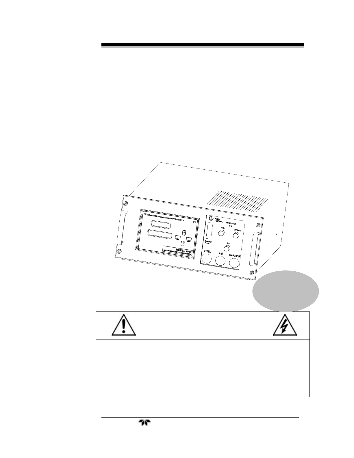
MODEL 4040
P/N M4040
ECO: #XX-XXXX
DATE 02/22/06
DANGER
Toxic and/or flammable gases or liquids may be present in this monitoring system.
Personal protective equipment may be required when servicing this instrument.
Hazardous voltages exist on certain components internally which may persist for
a time even after the power is turned off and disconnected.
Only authorized personnel should conduct maintenance and/or servicing. Before
conducting any maintenance or servicing, consult with authorized
supervisor/manager.
Teledyne Analytical Instruments i

Series 4040
Copyright © 2003 Teledyne Analytical Instruments
All Rights Reserved. No part of this manual may be reproduced, transmitted, transcribed,
stored in a retrieval system, or translated into any other language or computer language in
whole or in part, in any form or by any means, whether it be electronic, mechanical,
magnetic, optical, manual, or otherwise, without the prior written consent of Teledyne
Analytical Instruments, 16830 Chestnut Street, City of Industry, CA 91749-1580.
Warranty
This equipment is sold subject to the mutual agreement that it is warranted by us free from
defects of material and of construction, and that our liability shall be limited to replacing or
repairing at our factory (without charge, except for transportation), or at customer plant at
our option, any material or construction in which defects become apparent within one year
from the date of shipment, except in cases where quotations or acknowledgements provide
for a shorter period. Components manufactured by others bear the warranty of their
manufacturer. This warranty does not cover defects caused by wear, accident, misuse,
neglect or repairs other than those performed by Teledyne or an authorized service center.
We assume no liability for direct or indirect damages of any kind and the purchaser by the
acceptance of the equipment will assume all liability for any damage which may result from
its use or misuse.
We reserve the right to employ any suitable material in the manufacture of our apparatus,
and to make any alterations in the dimensions, shape or weight of any parts, in so far as
such alterations do not adversely affect our warranty.
Important Notice
This instrument provides measurement readings to its user, and serves as a tool by which
valuable data can be gathered. The information provided by the instrument may assist the user
in eliminating potential hazards caused by his process; however, it is essential that all
personnel involved in the use of the instrument or its interface be properly trained in the
process being measured, as well as all instrumentation related to it.
The safety of personnel is ultimately the responsibility of those who control process
conditions. While this instrument may be able to provide early warning of imminent
danger, it has no control over process conditions, and it can be misused. In particular, any
alarm or control systems installed must be tested and understood, both as to how they
operate and as to how they can be defeated. Any safeguards required such as locks, labels,
or redundancy, must be provided by the user or specifically requested of Teledyne at the
time the order is placed.
Therefore, the purchaser must be aware of the hazardous process conditions. The purchaser
is responsible for the training of personnel, for providing hazard warning methods and
instrumentation per the appropriate standards, and for ensuring that hazard warning devices
and instrumentation are maintained and operated properly.
Teledyne Analytical Instruments, the manufacturer of this instrument, cannot accept
responsibility for conditions beyond its knowledge and control. No statement expressed or
implied by this document or any information disseminated by the manufacturer or its
agents, is to be construed as a warranty of adequate safety control under the user’s process
conditions.
ii Teledyne Analytical Instruments
Safety Messages
Your safety and the safety of others are very important. We have
provided many important safety messages in this manual. Please read
these messages carefully.
A safety message alerts you to potential hazards that could hurt you
or others. Each safety message is associated with a safety alert symbol.
These symbols are found in the manual and inside the instrument. The
definition of these symbols is described below:
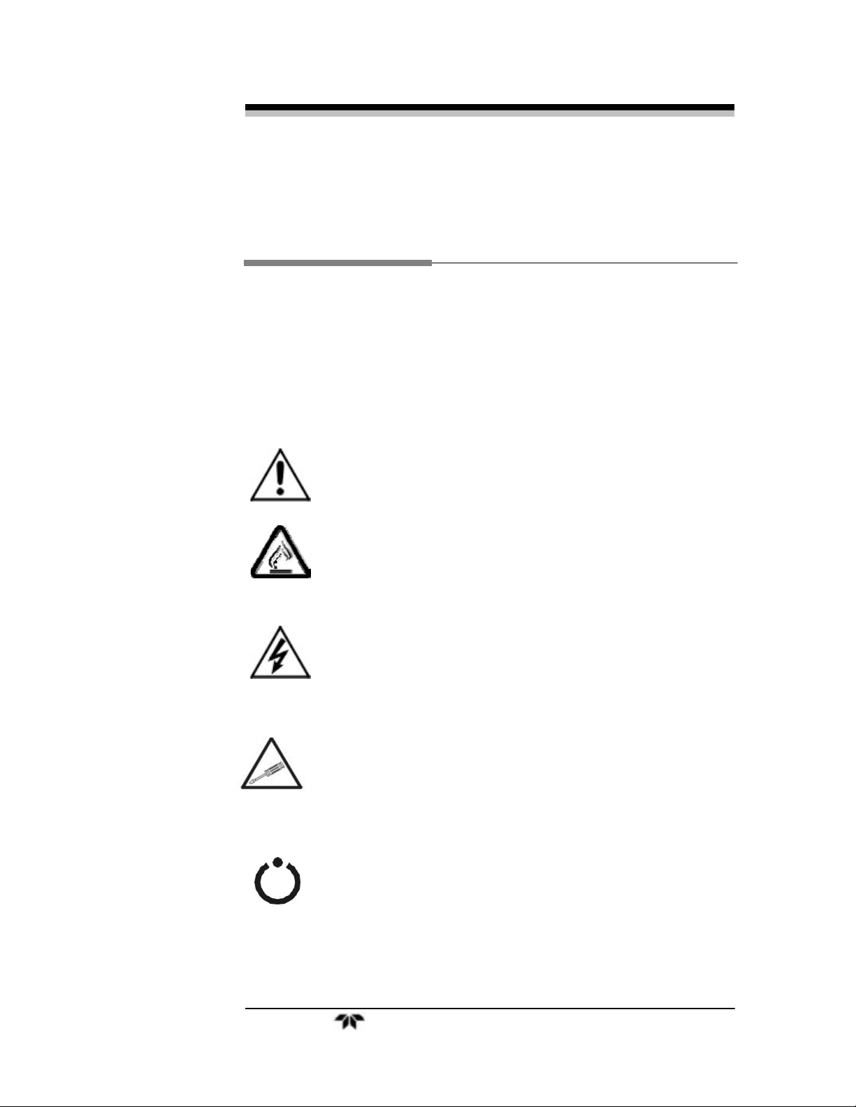
No
Symbol
GENERAL
WARNING/CAUTION: Refer to the
instructions for details on the specific danger. These
cautions warn of specific procedures which if not
followed could cause bodily Injury and/or damage the
instrument.
CAUTION: HOT SURFACE WARNING: This warning is
specific to heated components within the instrument.
Failure to heed the warning could result in serious burns
to skin and underlying tissue.
WARNING: ELECTRICAL SHOCK HAZARD: Dangerous
voltages appear within this instrument. This warning is
specific to an electrical hazard existing at or nearby the
component or procedure under discussion. Failure to heed
this warning could result in injury and/or death from
electrocution.
Technician Symbol: All operations marked with this
symbol are to be performed by qualified maintenance
personnel only.
NOTE: Additional information and comments regarding
a specific component or procedure are highlighted in the
form of a note.
STAND-BY: This symbol indicates that the instrument is
on Stand-by but circuits are active.
Teledyne Analytical Instruments iii

Series 4040
CAUTION: THE ANALYZER SHOULD ONLY BE USED FOR THE
PURPOSE AND IN THE MANNER DESCRIBED IN
THIS MANUAL.
IF YOU USE THE ANALYZER IN A MANNER OTHER
THAN THAT FOR WHICH IT WAS INTENDED,
UNPREDICTABLE BEHAVIOR COULD RESULT
POSSIBLY ACCOMPANIED WITH HAZARDOUS
CONSEQUENCES.
This manual provides information designed to guide you through the
installation, calibration and operation of your new analyzer. Please read
this manual and keep it available.
Occasionally, some instruments are customized for a particular
application or features and/or options added per customer requests.
Please check the front of this manual for any additional information in
the form of an Addendum which discusses specific information,
procedures, cautions and warnings that may be specific to your
instrument.
Manuals do get misplaced. Additional manuals can be obtained from
Teledyne at the address given in the Appendix. Some of our manuals are
available in electronic form via the internet. Please visit our website at:
www.teledyne-ai.com.
iv Teledyne Analytical Instruments
Additional Safety Information
DANGER
COMBUSTIBLE GAS USAGE
This is a general purpose instrument designed for usage in a
non-hazardous area. It is the customer's responsibility to
ensure safety especially when combustible gases are being
analyzed since the potential of gas leaks always exist.
WARNING
The customer should ensure that the principles of operating
of this equipment are well understood by the user. Misuse of
this product in any manner, tampering with its components,
or unauthorized substitution of any component may
adversely affect the safety of this instrument.
Since the use of this instrument is beyond the control of
Teledyne, no responsibility by Teledyne, its affiliates, and
agents for damage or injury from misuse or neglect of this
equipment is implied or assumed.
WARNING: HYDROGEN GAS IS USED IN THIS INSTRUMENT AS
A FUEL. HYDROGEN IS EXTREMELY FLAMMABLE.
EXTREME CARE MUST BE USED WHEN WORKING
AROUND GAS MIXTURES CONTAINING
FLAMMABLE GASES.
A Successful leak check was performed at TI/AI on
the sample system of this instrument prior to
calibration, testing and shipping. Ensure that there
are no leaks in the fuel supply lines before applying
power to the system.
Always purge the entire system before performing
any maintenance and always leak check the system
after removing any tubing or fittings on the sample
Teledyne Analytical Instruments v
Series 4040
system. See the procedures for purging and leak
checking this instrument on the following pages.
If toxic gases or other hazardous materials are
introduced into the sample system, the same
precautions regarding leak checking and purging
apply to the sample lines and sample supply or
delivery lines.
WARNING: ELECTRICAL SHOCK HAZARD. WITH THE
EXCEPTION OF OPENING THE DOOR AND
ADJUSTING THE PRESSURE REGULATORS, FLOW
CONTROLLER, OR OBSERVING THE PRESSURE
GAUGES AND THE FLOWMETER, ONLY
AUTHORIZED AND SUITABLY TRAINED
PERSONNEL SHOULD PERFORM WORK INSIDE OF
THE INSTRUMENT. COMPONENTS WITHIN THE
COVER ON THE INSIDE OF THE DOOR, INSIDE THE
ISOTHERMAL CHAMBER (SAMPLE SYSTEM), AND
ON THE ELECTROMETER-AMPLIFIER PC BOARD
CONTAIN DANGEROUSLY HIGH VOLTAGE
SUFFICIENT TO CAUSE SERIOUS INJURY OR
DEATH.
There are the following three types of inaccessible
shock hazards within the Analyzer:
1. Line voltages and line related voltages such as
115 VAC which exists within the 230 VAC
versions as well. These voltages stop when the
Analyzer is turned off and the mains (line) cord is
removed from the instrument.
2. The sensor anode supply voltage (approximately
250 VDC). This voltage exists on the Flame
Guard, anode power supply, PCB, the
motherboard, and the anode/igniter terminals on
the sensor. THIS VOLTAGE WILL REMAIN
HAZARDOUS FOR MANY MINUTES AFTER THE
ANALYZER HAS BEEN TURNED OFF!
3. External hazardous voltages which may be
connected to the Analyzer alarm relay
connections.
vi Teledyne Analytical Instruments
Procedure for Removal of Internal Inaccessible
Shock Hazards
CAUTION: SERVICING OR MAINTENANCE OF THE ANALYZER
SHOULD ONLY BE DONE BY SUITABLE TRAINED
PERSONNEL. TO AVOID THESE INACCESSIBLE
HAZARDOUS VOLTAGES WHEN SERVICING THE
power cord from the Analyzer.
contacts.
SERIES 4060, PERFORM EACH OF THE FOLLOWING
STEPS, IN THE ORDER GIVEN, BEFORE SERVICING
BEGINS:
Switch off the power to the Analyzer and remove the main (line)
Remove all external voltages from the connections to the alarm
Wait one minute.
Discharge the anode supply voltage.
a. Connect one end of an insulated (to 1000 VDC or more)
clip lead to Analyzer chassis ground (the standoff for the
upper right corner of the mother PCB).
b. Put one end of a 500V rated 1000 ohm resistor in the
other end of the clip lead.
c. Check the voltage between chassis ground (the standoff
for the upper right corner of the mother PCB) and the top
side of R2 at PCB number B74671. It should be between
-5VDC and +5VDC. If is in that range, the inaccessible
hazardous voltage removal procedure is completed, if not
repeat steps 4.a and 4.b.
If it is absolutely necessary to work inside the instrument with power
on, use the ONE HAND RULE:
Work with one hand only.
Keep the other hand free without contacting any other object. This
reduces the possibility of a ground path through the body in case of
accidental contact with hazardous voltages.
WARNING: THIS INSTRUMENT IS DESIGNED TO BE OPERATED
IN A NONHAZARDOUS AREA. THE ANALYZER USES
HYDROGEN GAS AND/OR OTHER COMBUSTIBLE
GASES IN ITS OPERATION. THIS EQUIPMENT, IF
NOT USED AND MAINTAINED PROPERLY CAN BE
AN EXPLOSION HAZARD. THE ANALYZER,
Teledyne Analytical Instruments vii
Series 4040
DEPENDING ON THE APPLICATION, MAY ALSO USE
TOXIC GASES. IT IS THEREFORE, THE
CUSTOMER'S RESPONSIBILITY TO ENSURE THAT
PROPER TRAINING AND UNDERSTANDING OF THE
PRINCIPLES OF OPERATION OF THIS EQUIPMENT
ARE UNDERSTOOD BY THE USER. SINCE THE USE
OF THIS INSTRUMENT IS BEYOND THE CONTROL
OF TELEDYNE, NO RESPONSIBILITY BY TELEDYNE,
ITS AFFILIATES AND AGENTS FOR DAMAGE OR
INJURY RESULTING FROM MISUSE OR NEGLECT
OF THIS INSTRUMENT IS IMPLIED OR ASSUMED.
MISUSE OF THIS PRODUCT IN ANY MANNER,
TAMPERING WITH ITS COMPONENTS OR
UNAUTHORIZED SUBSTITUTION OF ANY
COMPONENT MAY ADVERSELY AFFECT THE
SAFETY OF THIS INSTRUMENT.
CAUTION: WHEN OPERATING THIS INSTRUMENT, THE DOORS
MUST BE CLOSED AND ALL COVERS SECURELY
FASTENED. THE GAUGES MUST BE IN PROPER
WORKING ORDER. DO NOT OVERPRESSURIZE THE
SYSTEM.
READ THIS MANUAL BEFORE OPERATING THE
INSTRUMENT AND ADHERE TO ALL WARNINGS
INCLUDED IN THIS MANUAL.
viii Teledyne Analytical Instruments

Table of Contents
Safety Messages ..........................................................................iii
Additional Safety Information .....................................................v
Procedure for Removal of Internal Inaccessible Shock Hazards vii
List of Figures..............................................................................xii
List of Tables..............................................................................xiii
Introduction .................................................................................15
1.1 Main Features of the Analyzer 15
1.2 Principle of Operation 16
1.3 Analyzer Description 16
1.4 Applications 16
Operational Theory .....................................................................17
2.1 Introduction 17
2.2 Sample System 18
2.2.2 Input Porting 18
2.2.2 Gas Flow Control System 20
2.2.3 Fuel and Blanket Air Systems 20
2.2.4 Flame Ionization Detection Cell 20
2.3 Detection Cell 20
2.3.1 Electrometer-Amplifier 22
2.3.2 Anode Power Supply 22
2.3.3 Flame Guard Circuit 22
2.3.4 Flame Ignition Circuit 22
Installation ...................................................................................25
3.1 Unpacking the Analyzer 25
3.2 Mounting the Analyzer 25
3.3 User Connections 26
3.3.1 Electrical Power Connections 26
Teledyne Analytical Instruments ix

Series 4040
3.3.3.1 Primary Input Power 29
3.3.3.2 Fuse Installation 29
3.3.3.3 50-Pin Equipment Interface Connector 29
3.3.3.4 Analog Output 29
3.3.3.5 Alarm Relays 30
3.3.3.6 Digital Remote Cal Inputs 32
3.3.3.7 Range ID Relays 33
3.3.3.8 Network I/O 33
3.3.3.9 Pin Out Table 33
3.3.4 RS-232 Port 35
3.3.5 Supporting Gases 35
3.3.5.2 Effluent 37
3.3.5.3 Sample Bypass Vent 37
3.3.5.4 Fuel and Air Connections 37
3.4 Placing the System in Operation 37
3.5 Activating the Support Gases 38
3.5.1 Air 38
3.5.2 Carrier Gas 38
3.5.3 Span Gas 38
3.5.4 Fuel 38
3.6 Flame Ignition 39
3.6.1 Verification of the Flame Guard Circuit 39
3.6.2 Ignition and/or Flame Guard Circuit Failure 40
3.6.3 Sample Pump 40
Operation .....................................................................................43
4.1 Analyzer Operation 43
4.2 Default Parameters 44
4.3 Style Conventions 44
4.4 Navigation and Data Entry 45
4.4.1 Arrow Keys 45
4.4.2 ENTER 45
4.4.3 ESCAPE 46
4.5 Menu Structure 47
4.5.1 Main Menus 48
x Teledyne Analytical Instruments

4.5.2 Expanded menus 49
4.6 Setting up an AUTO-CAL 53
4.7 Adjusting the GAIN 53
4.8 Password Protection 54
4.9 Logging Out 57
4.10 The Model Screen 58
4.11 System Self-Diagnostic Test 58
4.12 Span 59
4.13 The Alarms Function 60
4.14 The Range Function 62
4.15 Changing Stream 63
4.16 Analog output Adjustment 63
4.17 Standby 64
4.18 Advanced User Functions 65
4.18.1 Timing 65
Appendix......................................................................................67
A.1 Specifications and Initial Settings: 67
A.2 Recommended Spare Parts List 68
A.3 Drawing List 69
Teledyne Analytical Instruments xi

Series 4040
List of Figures
Figure 1-1: 19” Rack Piping Diagram-Model 4060 .....................22
Figure 1-2: Flame Ionization Cell...................................................24
Figure 3-1: Gas Connections.........................................................27
Figure 3-2: Equipment Interface Connector Pin Arrangement.......29
Figure 4-1: Front Panel View of Regulator and Gages..................48
xii Teledyne Analytical Instruments

List of Tables
Table 3-1: Analog Output Connections .........................................30
Table 3-4: Alarm Relay Contact Pins ............................................31
Table 3-5: Remote Calibration Connections..................................32
Table 3-6: Range ID Relay Connections.......................................33
Table 3-7: Pin out of 50 pin D-Sub Connector...............................33
Table 3-8: Commands via RS-232 Input.......................................35
Table 3-9: Required RS-232 Options............................................35
Teledyne Analytical Instruments xiii

Series 4040
xiv Teledyne Analytical Instruments

Introduction
Introduction
Teledyne Analytical Instruments Series 4040, Methane/ Nonmethane Analyzer, is designed to measure the quantity of variety of
hydrocarbons present in the sample gas. The Analyzer is a
microprocessor controlled digital instrument based on Teledyne’s highly
successful Model 402R series analog Total Hydrocarbon Analyzer,
coupled with a gas separation Column and a switching valve. The
Analyzer allows for the separation and measurement of methane
hydrocarbon from the rest of the hydrocarbons in the low ppm range.
1.1 Main Features of the Analyzer
The Analyzer is sophisticated yet simple to use. A dual display on
the front panel prompts and informs the operator during all phases of
operation. The main features of the analyzer include:
1. Easy-to-use front panel interface that includes a red 5-digit LED
display and a vacuum fluorescent display (VFD), driven by
microprocessor electronics.
2. High resolution, accurate readings of concentration.
3. Versatile analysis with three user-definable analysis ranges.
4. Microprocessor based electronics: 8-bit CMOS microprocessor
with 32 kB RAM and 128 kB ROM.
5. Auto ranging allows analyzer to automatically select the proper
preset range for a given measurement. Manual override allows
the user to lock onto a specific range of interest.
6. Two adjustable concentration alarms and a system failure alarm.
7. Extensive self-diagnostic testing at startup and on demand.
8. RS-232 serial digital port for use with a computer or other digital
communication device.
9. Analog outputs for concentration and range identification (0-1
VDC standard and isolated 4-20 mA dc).
10. Superior Accuracy
Teledyne Analytical Instruments 15

Series 4040
1.2 Principle of Operation
The sample is brought to a heated compartment (50 - 80° C per
application) and into a sample loop and a 10-port, 2 position (Position A
& B) switching valve. In valve Position B the carrier gas, nitrogen,
pushes the sample into a Column to separate methane from the
remaining hydrocarbons. The eluted gases are analyzed for methane in
the FID detector. In valve Position A, the flow through the Column is
reversed and the carrier gas pushes the sample into the FID to detect
NMH. The electrical output is directly proportional to the concentration
of the ionizable hydrocarbons present in the sample stream.
1.3 Analyzer Description
The standard analyzer is housed in a sheet steel equipment case
flush-mounted in a 19" rack. The front interface panel is mounted on a
door which, when opened, allows convenient access to the Analyzer
electronics. The entire front panel can slide out of the chassis to provide
greater access to the electronics and to the sample system. Gas pressure
and flow controls are mounted on the front panel adjacent to the LED
and VFD displays and user interface.
At the rear of the instrument are ports for the introduction of air,
carrier, fuel, span, and sample gas. A single 50-pin user-interface cable
connector contains input/output and alarm signals available to the user.
An RS-232 port is also available at the rear panel for connection to a
remote computer or other digital communication device. The Analyzer is
set up for either 120 VAC 60 Hz or 230 50/60 Hz operation depending
on the customer’s requirements. The appropriate power cord for your
unit has been shipped with this instrument.
1.4 Applications
• Monitoring the ambient air for methane/ non-methane in
chemical and petrochemical plants.
• Fugitive emission monitoring.
• Process emission gases in the chemical industry.
• Detecting trace methane/ non-methane in air.
• Detecting atmospheric pollutants.
16 Teledyne Analytical Instruments

Operational Theory Series 4040
Operational Theory
2.1 Introduction
The sample is brought to sample loop and a 10-port switching valve
kept inside a heated (Temperature: 50° - 80° C per application)
SAMPLE Chamber. Using a carrier gas and a microprocessor actuated
switching valve, a fixed volume of sample collected in the Sample Loop,
is pushed into the Column maintained at a constant temperature. The
eluted gas is analyzed for methane in a FID detector. Immediately, at
the end of the analysis of methane, the Valve is switched to reverse the
flow through the Column, causing propane as NMH to elute and be
analyzed.
Series 4040 uses a Flame Ionization Detector to sense hydrocarbons.
The FID was selected based on the positive performance and extensive
experience in the use of this detector in other Teledyne analyzers namely
Model 402R and Model 4020. The FID has proven itself to be a rugged,
stable, long life sensor giving years of trouble free operation in various
applications.
A packed Column was used at a constant temperature to separate
methane from the remaining non-methane hydrocarbons.
The analysis has 2 modes: Methane Mode and Non-methane Mode.
1) Methane Mode (POSITION B)
In this mode, the eluted sample from the column is fed to the FID for
the analysis of the methane content of the hydrocarbons.
2) Non-methane Mode (POSITION A)
During this mode, the FID detector is monitoring Non-methane
hydrocarbons, such as propane. At the end of the cycle, the methane
content of the sample (from Position B) is added to the NMH value
to compute THC values.
Teledyne Analytical Instruments 17

Operational Theory
The Series 4040 Analyzer is composed of three subsystems:
1. Sample System
2. Detector Cell
3. Electronic Signal Processing, Display and Control
2.2 Sample System
The Analyzer contains three (3) separate isothermal chambers
controlled by individual PID temperature controllers, viewed just behind
the Front Panel. The three chambers, ‘SAMPLE’, ‘FID’, and
‘COLUMN’ are described below.
The Analyzer consists of a SAMPLE Chamber containing the 10port switching valve and 2 sample loops. The Analyzer also consists of
an ‘FID’ chamber containing the Flame, pressure regulators, pressure
gauges and flow restrictors. The ‘COLUMN’ is housed in a separate
‘COLUMN’ enclosure and maintained at a close temperature.
2.2.2 Input Porting
The Analyzer is equipped with ports for the introduction of air, fuel,
carrier gas, span, and sample gas. It is imperative that these gases are
supplied at constant pressures using two stage stainless steel diaphragm
gas regulators. The recommended pressure range is 30 to 60 psig.
However, the Span gas should be supplied at a pressure of 20 psig to the
restrictor fitting on the Span/Sample Manifold (optional) on the back of
the Analyzer.
18 Teledyne Analytical Instruments
Operational Theory Series 4040
S
SAMPLE SPAN
S
SPAN/SAMPLE MANIFOLD
(OPTIONAL)
VENT
SAMPLE
SAMPLE IN
PUMP
FILTER
SAMPLE
FLOW
F-1
0.1 - 2 LPM
CARRIER IN
2
(N )
SENSOR VENT
(H )
AIR IN
2
FUEL
IN
OUT
FLOW
- 60 C TYP)
(50
FID CHAMBER
C TYP)
COLUMN
CHAMBER
(70
REG. 1
P. REG. 1
CARRIER
P. REG. 2
P. REG. 3
AIR
F.I.D.
FUEL
SENSOR
IN
R1
R2
IN
IN
R3
SAMPLE CHAMBER
(50 - 80 C PER
APPLICATION)
CH4 MODE
(POSITION B)
SAMPLE
LOOP #1
3
4
2
1
10
9
5
6
7
8
SAMPLE
LOOP #2
2 POSITION
10-PORT
VALVE
NMH MODE
(POSITION A)
LOOP #1
SAMPLE
3
2
1
10
4
5
6
7
8
9
SAMPLE
LOOP #2
CONTROL
SV1
N.C.
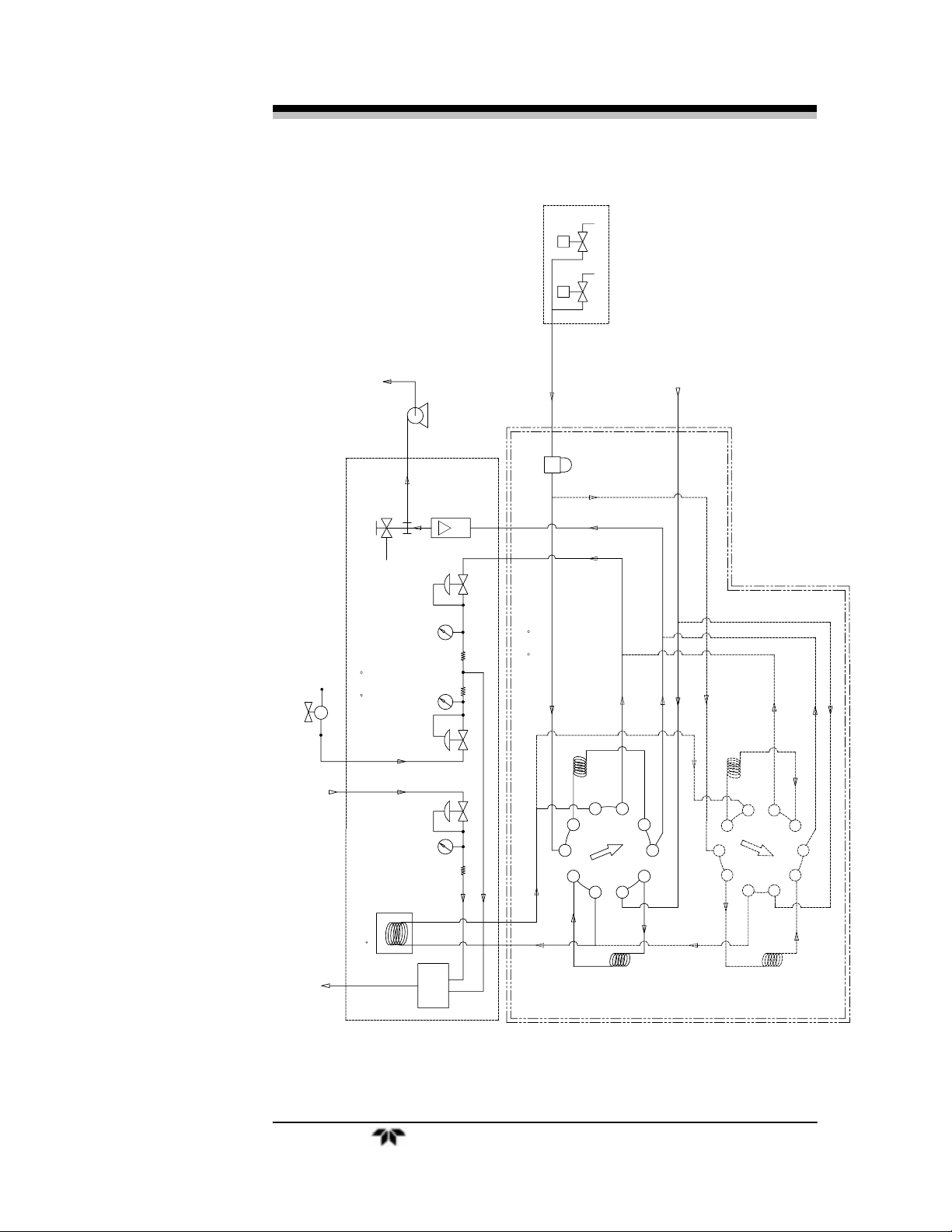
Figure 2-1 19” Rack Piping Diagram-Model 4040
Teledyne Analytical Instruments 19
Operational Theory
2.2.2 Gas Flow Control System
The Piping diagram is shown in Fig. 2-1. A 10 port switching valve
is used to control and direct gas flows including sampling, back flush,
and carrier gas. The fixed volume sample loop ensures the same volume
of sample injection in the Column every cycle.
2.2.3 Fuel and Blanket Air Systems
Stable flow is achieved by maintaining a constant pressure across
restrictors upstream from the cell. Each system incorporates an adjustable
pressure regulator, pressure gauge, and restrictor. A flame out light is
included to indicate when the flame fails. A fuel shut-off solenoid valve,
mounted on the line that supplies fuel, stops the fuel flow in case of flame
failure. This valve is located in line with the fuel port.
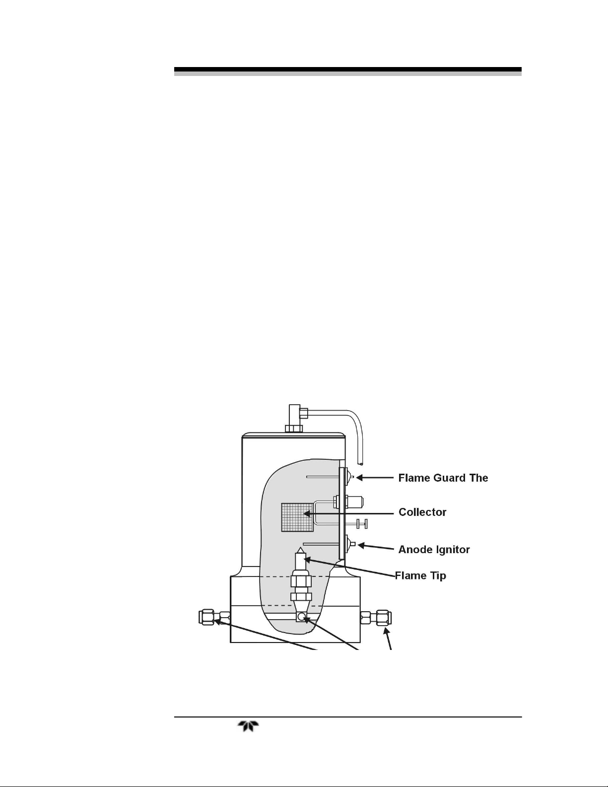
2.2.4 Flame Ionization Detection Cell
The carrier gas containing sample and fuel are combined within a tee
fitting located in the isothermal chamber. The mixed gas is emitted from
a burner within the sensor assembly. Blanket air is introduced into the
sensor (or cell) by means of a separate fitting that is located in the base
section of the assembly. The upper half of the assembly houses the
anode-igniter, collector, and flame guard thermistor.
2.3 Detection Cell
The upper section of the stainless steel flame ionization cell houses
the cylindrical collector electrode, the high voltage (+260 VDC) anodeigniter coil, and the sensing thermistor of the flame guard circuit (see
cell cross-section Figure 2-2).
WARNING: DANGEROUS HIGH VOLTAGE EXISTS AT THE
ANODE IGNITER COIL (+260 VDC). DO NOT
ATTEMPT TO DISCONNECT THE IGNITER COIL
CABLE OR DISASSEMBLE ANY OF THE FLAME
IONIZATION CELL COMPONENTS WITHOUT
TURNING OFF THE POWER AND DISCONNECTING
THE POWER CORD.
The collector is interconnected with the electrometer-amplifier PC
board by a coaxial cable. Although the cable and fittings are intended for
coaxial service, the cable is actually being used as a shielded singleconductor connection.
20 Teledyne Analytical Instruments
Operational Theory Series 4040
The anode-igniter, as its name implies, serves two functions. When
relay K2 at PCB part number B74671 is energized, the coil becomes an
electrical heating element that glows red-hot and ignites the hydrogen
fuel. When relay K2 at B74671 is de-energized, the coil is connected to
the +260 volt DC terminal of the anode-flame guard power supply PC
board. In this configuration, the necessary potential difference is
established between the coil (anode) and collector to promote ionization
of the burned hydrocarbons. The coil functions as the high voltage anode
in all three-range positions of the selector switch.
The thermistor acts as the sensor in the flame guard circuit. Its
ambient temperature resistance is in the 100 K ohms region. When the
flame is ignited, its resistance is reduced by a factor of 100. The
thermistor is coupled to a semiconductor control circuit on the anodeflame guard power supply PC board, which will be described in a
following section.
The cell electrodes of both the anode-igniter and flame guard
thermistor are connected to the electronics chassis by means of a plug-in
cable.
Figure 2-2: Flame Ionization Cell
Teledyne Analytical Instruments 21
 Loading...