

Page 1
Total Hydrocarbon Analyzer Table of Contents
INSTRUCTION MANUAL
MODEL 402R-EU
TOT AL HYDROCARBON ANALYZER
Teledyne
Analytic al Instruments
MODEL 402R
MED
LO
HI
IGNITE
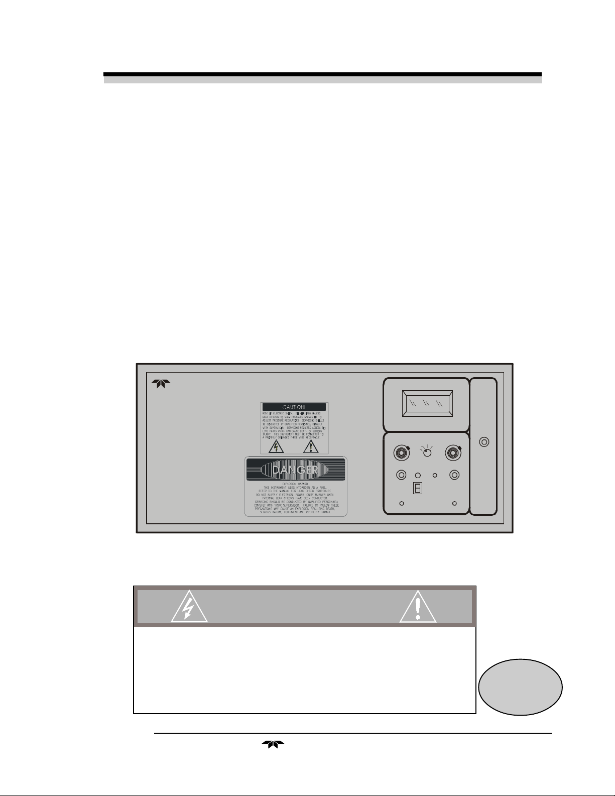
DANGER
HIGHLY TOXIC AND OR FLAMMABLE LIQUIDS OR GASES MAY BE PRESENT IN THIS MONITORING
SYSTEM.
PERSONAL PROTECTIVE EQUIPMENT MAY BE REQUIRED WHEN SERVICING THIS SYSTEM.
HAZARDOUS VOLTAGES EXIST ON CERTAIN COMPONENTS INTERNALLY WHICH MAY PERSIST FOR
A TIME EVEN AFTER THE POWER IS TURNED OFF AND DISCONNECTED.
ONLY AUTHORIZED PERSONNEL SHOULD CONDUCT MAINTENANCE AND/OR SERVICING. BEFORE
CONDUCTING ANY MAINTENANCE OR SERVICING CONSULT WITH AUTHORIZED SUPERVISOR/
MANAGER.
P/N M66893
ECO: #99-0323
08/06/1999
Teledyne Analytical Instruments
i
Page 2

Table of Contents Model 402R-EU
Copyright © 1999 Teledyne Electronic Technologies/Analytical Instruments
All Rights Reserved. No part of this manual may be reproduced, transmitted, transcribed, stored in a
retrieval system, or translated into any other language or computer language in whole or in part, in any form
or by any means, whether it be electronic, mechanical, magnetic, optical, manual, or otherwise, without the
prior written consent of Teledyne Electronic Technologies/Analytical Instruments, (TET/AI)
16830 Chestnut Street, City of Industry, CA 91749-1580.
Warranty
This equipment is sold subject to the mutual agreement that it is warranted by us free from defects of
material and of construction, and that our liability shall be limited to replacing or repairing at our factory
(without charge, except for transportation), or at customer plant at our option, any material or construction
in which defects become apparent within one year from the date of sale, except in cases where quotations or
acknowledgements provide for a shorter period. Components manufactured by others bear the warranty of
their manufacturer. This warranty does not cover defects caused by wear, accident, misuse, or neglect. We
assume no liability for direct or indirect damages of any kind and the purchaser by the acceptance of the
equipment will assume all liability for any damage which may result from its use or misuse.
We reserve the right to employ any suitable material in the manufacture of our apparatus, and to make any
alterations in the dimensions, shape or weight of any parts, in so far as such alterations do not adversely
affect our warranty.
Important Notice
This instrument is intended to be used a tool to gather valuable data. The information provided by the
instrument may assist the user in eliminating potential hazards caused by the process that the instrument is
intended to monitor; however, it is essential that all personnel involved in the use of the instrument or its
interface with the process being measured be properly trained in the process itself, as well as all instrumentation related to it.
The safety of personnel is ultimately the responsibility of those who control process conditions. While this
instrument may be able to provide early warning of imminent danger, it has no control over process conditions, and can be misused. In particular, any alarm or control system installed must be tested and understood, both as to how they operate and as to how they can be defeated. Any safeguards required such as
locks, labels, or redundancy must be provided by the user or specifically requested of Teledyne.
The purchaser must be aware of the hazardous conditions inherent in the process(es) he uses. He is responsible for training his personnel, for providing hazard warning methods and instrumentation per the appropriate standards, and for ensuring that hazard warning devices and instrumentation are maintained and
operated properly.
TET/AI, the manufacturer of this instrument, cannot accept responsibility for conditions beyond its knowledge and control. No statement expressed or implied by this document or any information disseminated
by the manufacturer or his agents is to be construed as a warranty of adequate safety control under the
user's process conditions.
ii
Teledyne Analytical Instruments
Page 3
Total Hydrocarbon Analyzer Table of Contents
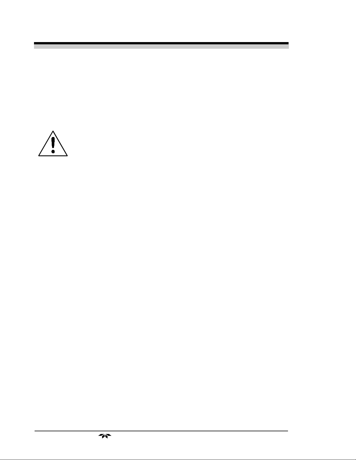
IN ORDER TO AVOID HAZARDOUS CONDITIONS, DAMAGE TO THE
INSTRUMENT, AND TO ASSURE PROPER OPERATION, THE USER SHOULD
READ THIS MANUAL BEFORE INSTALLING AND OPERATING THE 402R-EU
THIS INSTRUMENT SHOULD ONLY BE MAINTAINED BY SUITABLY
TRAINED AND QUALIFIED PERSONNEL.
IF USED OUTSIDE OF THE SPECIFICATIONS (SEE APPENDIX A), THE INSTRUMENT MAY BE DAMAGED AND HAZARDOUS CONDITIONS MAY BE
PRODUCED.
Model 402R-EU complies with all of the requirements of the Commonwealth of Europe (CE) for Radio Frequency Interference, Electromagnetic Interference (RFI/EMI), and Low Voltage Directive
(LVD).
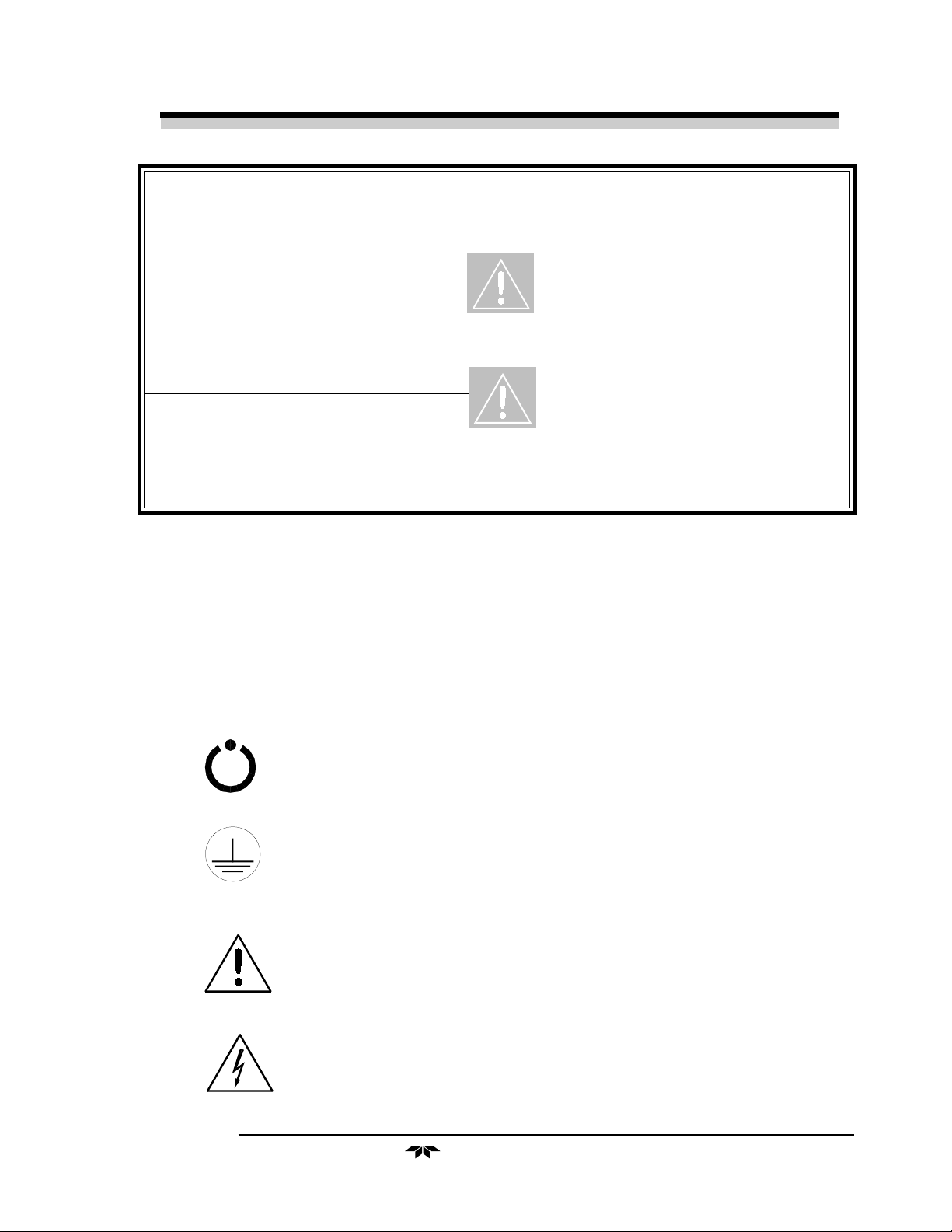
The following International Symbols are used throughout the Instruction Manual for your visual and immediate warnings and when
you have to attend CAUTION while operating the instrument:
STAND-BY, Instrument is on Stand-by,
but circuit is active
GROUND
Protective Earth
CAUTION, The operator needs to refer to the manual
for further information. Failure to do so may
compromise the safe operation of the equipment.
CAUTION, Risk of Electric Shock
Teledyne Analytical Instruments
iii
Page 4

Table of Contents Model 402R-EU
T a ble of Contents
VI Safety Informations.............................................................VI
1 Introduction
1.1 Principle of Operation .................................................. 1-1
1.2 Analyzer Description ................................................... 1-1
1.3 Sampling System ........................................................ 1-2
1.3.1 Input Porting..................................................... 1-2
1.3.2 Sample Flow Control System ........................... 1-2
1.3.3 Fuel and Blanket Air Systems .......................... 1-3
1.3.4 Flame Ionization Detection Cell........................ 1-3
1.4 Applications................................................................. 1-3
2 Operational Theory
2.1 Electronics................................................................... 2-1
2.1.1 Detection Cell ................................................... 2-3
2.1.2 Electrometer-Amplifier...................................... 2-3
2.1.3 Differential Power Supply ................................. 2-4
2.1.4 Anode Power Supply........................................ 2-4
2.1.5 Flame Guard Circuit ......................................... 2-4
2.1.6 Flame Ignition Circuit........................................ 2 -4
2.1.7 Proportional Temperature Control Circuit ........ 2 -4
2.1.8 Output............................................................... 2 -5
iv
3 Installation
3.1 Electrical Requirements and Connections .................. 3-1
3.1.1 Primary Power.................................................. 3- 2
3.1.2 Voltage Output Signal ...................................... 3-3
3.2 Gas Connections ......................................................... 3-3
3.2.1 Supporting Gases............................................. 3-4
3.2.2 Sample Gas...................................................... 3-5
3.2.3 Effluent ............................................................. 3-5
3.2.4 Sample Bypass Vent ........................................ 3-5
3.2.5 Fuel and Air Connections ................................. 3-5
3.2.6 Fuses................................................................ 3-6
4 Operations
4.1 Equipment................................................................... 4-1
4.2 Preliminary Power-Off Check List ............................... 4-2
4.3 Preliminary Electronic Adjustment .............................. 4-3
4.3.1 Meter-Recorder Alignment ............................... 4-3
4.4 Placing the System in Operation................................. 4- 4
Teledyne Analytical Instruments
Page 5

Total Hydrocarbon Analyzer Table of Contents
4.5 Activating the Support Gases...................................... 4-4
4.5.1 Air..................................................................... 4- 4
4.5.2 Zero Gas .......................................................... 4-4
4.5.3 Span Gas ......................................................... 4-5
4.5.4 Fuel .................................................................. 4-6
4.6 Flame Ignition ............................................................. 4-6
4.6.1 Verification of the Flame Guard Circuit ............ 4-6
4.6.2 Ignition and/or Flame Guard Circuit Failure ..... 4-7
4.7 Calibration................................................................... 4-7
4.8 Stabilization Period ..................................................... 4-8
4.9 Sampling ..................................................................... 4-8
4.10 Routine Operation ....................................................... 4-9
4.10.1Verification of Calibration ................................. 4 -9
4.10.2Supporting Gases........................................... 4-10
5 Maintenance & Troubleshooting
5.1 Measuring Circuit Electrical Checks............................ 5 -2
5.1.1 Loss of Zero Control......................................... 5-3
5.1.2 Anode Voltage Check....................................... 5-3
5.1.3 Electronic Stability ............................................ 5-4
5.1.4 Printed Circuit Board Replacement .................. 5-4
5.1.5 Collector Cable................................................. 5-5
5.2 Temperature Control Electronic Check...................... 5-5
5.3 Ignition and/or Flame Guard Circuit Checks ............... 5-8
5.3.1 Flame Guard Circuit Calibration....................... 5-9
5.4 Sampling System ...................................................... 5-10
5.5 Printed Circuit Board Descriptions ............................ 5-10
5.5.1 Flame Guard and Anode Power Supply
Printed Circuit Board ...................................... 5-11
5.5.2 Regulated Differential Power Supply
Printed Circuit Board ...................................... 5-12
5.5.3 Proportional Temperature Controller
Printed Circuit Board ...................................... 5-13
5.5.4 Electrometer-Amplifier PC Board ................... 5-15
5.5.5 Comparator Alarm Printed Circuit Board........ 5-17
Appendix
Specifications ...................................................................... A-1
Application Data .................................................................. A-2
Recommended Spare Parts List ......................................... A-3
Drawing List ........................................................................ A-4
Teledyne Analytical Instruments
v
Page 6

Table of Contents Model 402R-EU
vi
Teledyne Analytical Instruments
Page 7

Total Hydrocarbon Analyzer Introduction
Introduction
The Teledyne Electronic Technologies/Analytical Instruments
(TET/AI) Model 402R-EU Total Hydrocarbon Analyzer meets or exceeds
all of the requirements of the Commonwealth of Europe (CE) for Radio
Frequency Interference and Electromagnetic Interference (RFI/EMI)
protection and Low Voltage Directive (LVD). The analyzer is designed to
measure the quantity of hydrocarbons present in a positive pressure sample
as equivalent methane.
1.1 Principle of Operation
The sample gas is mixed with a fuel (normally a composition of
hydrogen and nitrogen) and burned in an atmosphere of “blanket air”. The
ions formed in the burning process cause an electrical conduction between
two electrodes in the combustion chamber (or detector cell) that is amplified by a highly sensitive electrometer-amplifier circuit. The electrical
output of the electrometer-amplifier is directly proportional to the quantity
of flame ionizable hydrocarbons present, and is linear over the range of
0-10,000 PPM methane.
1.2 Analyzer Description
The information contained in this manual describes individual analyzers of the Model 402R-EU standard series. In cases of special design, other
factors may apply requiring additional or supplementary information.
These special considerations will be described in detail on specific application pages labelled Addenda, in each manual. When the Model 402R-EU is
a part of a larger system, it is subordinate to that system, and specific
installation and operation conditions of that system will apply. Consult
system sections of the manuals for those applications, where conditions
specific to those systems will be detailed.
Teledyne Analytical Instruments
1-1
Page 8
Chapter 1 Model 402R-EU
To best suit the needs of the purchaser, specialized designs are available. Details of the design differences may be found in the various drawings (outline, assembly, schematic, wiring, and piping diagrams) in the
drawings section at the rear of the manual. The standard analyzer is
housed in a sheet steel equipment case that has been designed for flushmounting in a 19" rack.
CAUTION: Since the measured component for the 402R-EU is hydrocarbon
content, and since hydrocarbon lubricants and conditioners as
well as synthetic plastics are common to instrumentation
supply processes, utmost precaution must be taken at all times
to specify hydrocarbon-free gases, regulator diaphragms and
supplies.
1.3 Sampling System
All components used to control the sample and supporting gases, as
well as the combustion portion of the detector cell, are located inside,
behind the electronics control panel. The basic analyzer consists of an
isothermal chamber containing the pressure regulators, pressure gauges and
flow restrictors. The temperature within the chamber is maintained at
125°F by a heating element. The regulated temperature of the chamber
insures stable gas flow. An optional sample selector module is an integral
gas selector panel inside the instrument enclosure for conveniently switching between sample and calibration gases. When installed, it is part of the
isothermal chamber. The bypass flow is also controlled from this optional
panel.
1.3.1 Input Porting
The analyzer is equipped with ports for the introduction of air, fuel,
zero, span, and sample gas.
1.3.2 Sample Flow Control System
Stable sample flow is achieved by maintaining a constant pressure
across a restrictor through the use of a back-pressure regulation system,
which includes an adjustable regulator, pressure gauge, throttle valve, and
flowmeter. The throttle valve and flowmeter are included so that the
bypass flow required by the back-pressure regulator can be limited. Without these controls, a high sample point pressure would result in unnecessary sample waste through the back-pressure regulator.
The components of the system are arranged so that no dead volume is
present in the sample path to the detector cell. This guarantees rapid response to changes in hydrocarbon concentration—a fact that can be dem-
Teledyne Analytical Instruments1-2
Page 9

Total Hydrocarbon Analyzer Introduction
onstrated when zero and span gas are exchanged during the standardization
procedure.
The restrictors used in the system look alike; however, they are not
interchangeable.
1.3.3 Fuel and Blanket Air Systems
The fuel and blanket air systems use similar components. Stable flow
is achieved by maintaining a constant pressure across restrictors upstream
from the cell. Each system incorporates an adjustable pressure regulator,
pressure gauge, and restrictor. A flame out light is included to indicate
when the flame fails. A fuel shut-off solenoid valve, mounted on the line
that supplies hydrogen, stops the fuel flow in case of flame failure. This
valve is located in line with the fuel port; except for instruments using
hydrogen as the sample gas. In this case, the sample is used as fuel and the
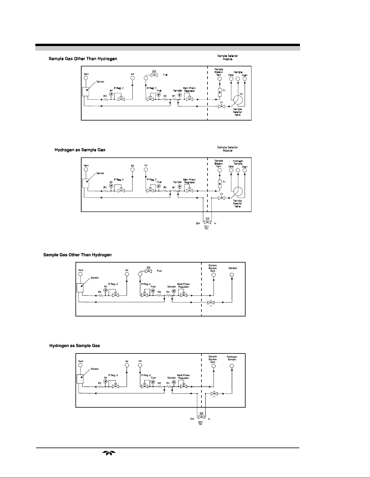
valve is located in line with the sample port. See Figure 1-1A for a flow
schematic for instruments equipped with a sample selector module. Figure
1-1B shows the flow schematic for instruments without the optional gas
selector module.
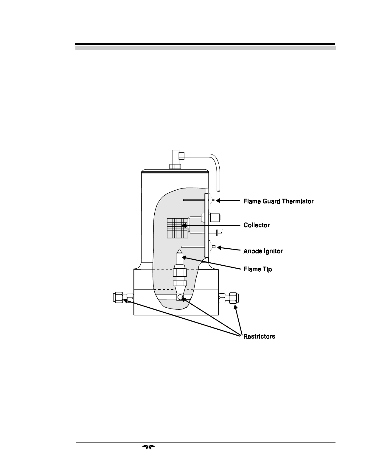
1.3.4 Flame Ionization Detection Cell
The sample and fuel are combined within a tee fitting located in the
isothermal chamber. The mixed gas is emitted from a burner within the
sensor assembly. Blanket air is introduced into the sensor (or cell) by
means of a separate fitting that is located in the base section of the assembly. The upper half of the assembly houses the anode-igniter, collector, and
flame guard thermistor. The cell is located at the left hand front area inside
the enclosure for easy access. See Figure 1-2.
1.4 Applications
• Monitoring the purity of oxygen, argon, nitrogen and other
gases in the manufacture of microcircuits.
• Monitoring hydrocarbon contamination in air liquefaction and
other gas production processes.
• Gas purity certification.
• Detecting trace hydrocarbons in ambient air.
• Detecting atmospheric pollutants.
• Cryogenics.
• Monitoring for fuel leakage or toxic solvents.
• Monitoring hydrocarbons in a wide range of process streams.
Teledyne Analytical Instruments
1-3
Page 10
Chapter 1 Model 402R-EU
Figure 1-1A: Schematic Flow Diagram With Gas Selector Panel
Figure 1-1B: Schematic Flow Diagram Without Gas Selector Panel
Teledyne Analytical Instruments1-4
Page 11
Total Hydrocarbon Analyzer Introduction
Figure 1-2: Flame Ionization Cell
Teledyne Analytical Instruments
1-5
Page 12

Chapter 1 Model 402R-EU
Teledyne Analytical Instruments1-6
Page 13
Total Hydrocarbon Analyzer Operational Theory
Operational Theory
2.1 Electronics
The analyzer features semiconductor circuitry throughout. Integrated
(IC) circuits are employed in the highly sensitive electronic circuits of the
instrument to reduce circuit component requirements and increase reliability. Aside from the necessary power transformers, three fuses, and electrical controls, all circuitry is mounted on plug-in type printed circuit cards.
The circuitry has been sectionalized so that spare circuit cards can be
employed without the use of expensive test equipment or the services of a
highly-trained technician. With spare circuit cards available for replacement, you will only need a multimeter to isolate and remedy an electronic
malfunction.
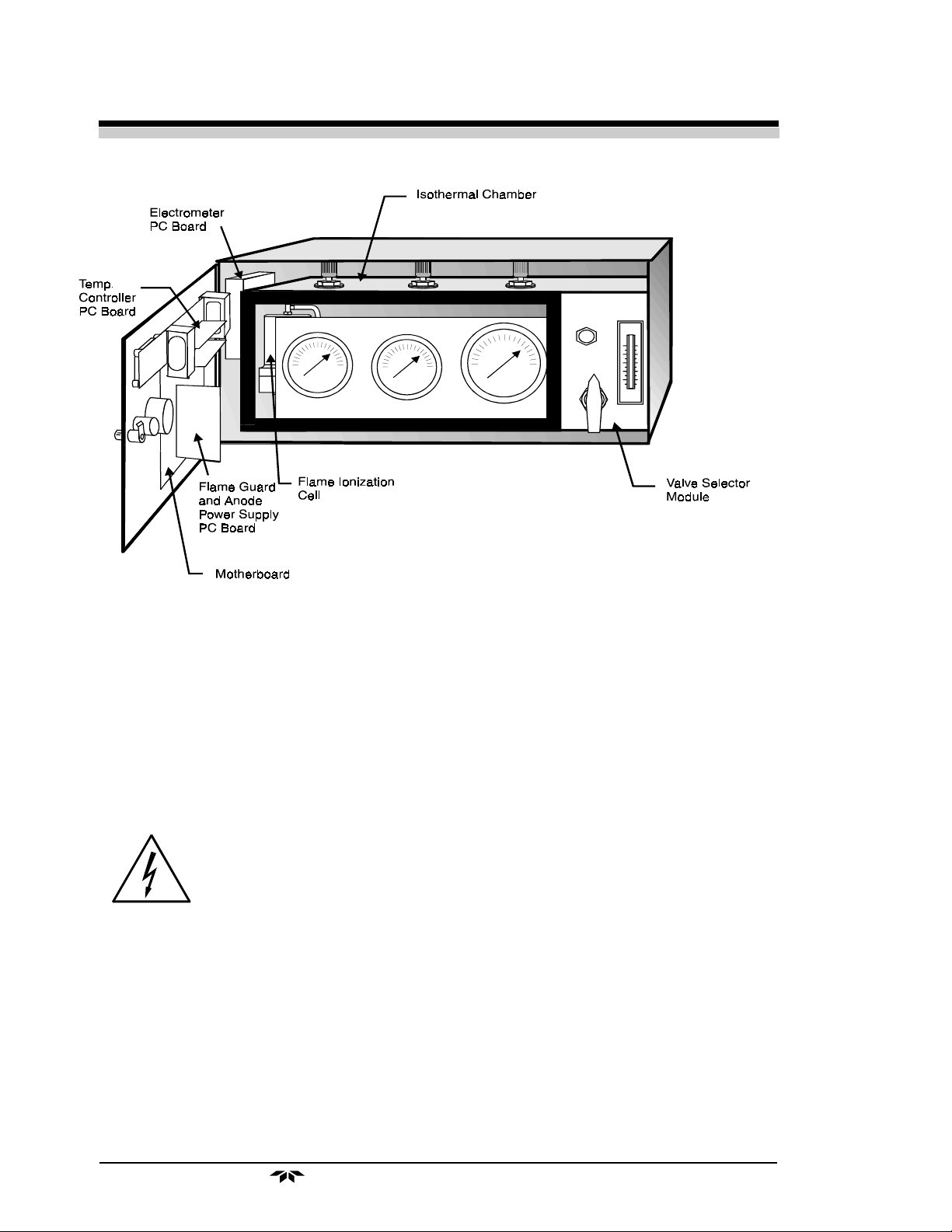
All the electronic PC board units (except the electrometer-amplifier)
plug into an interconnecting unit called the motherboard. See Figure 2-1
for motherboard location.
WARNING: The PCBs in the 402R-EU contain dangerously high
voltages. Ensure that all power to the instrument has been
removed before disconnecting or handling any of the
PCBs.
MOVAL OF INTERNAL INACCESSIBLE SHOCK HAZARDS").
The only electromechanical devices used are the control and fuel shutoff relays in the flame guard circuit.
The isothermal chamber components including the detector cell are
interconnected with the electronics chassis by means of plug-in cables.
The bulk of the electronic circuitry is located behind the hinged door
of the analyzer. Access to the interior of the analyzer is gained by rotating
(See Section 1 Page VII: "PROCEDURE FOR RE-
Teledyne Analytical Instruments
2-1
Page 14
Chapter 2 Model 402R-EU
Figure 2-1: View Inside 402R-EU Cabinet
(with internal door cover removed)
the doorknob located on the upper right-hand side of the hinged door, and
swinging it out.
To gain access to the electronics mounted on the inside of the door,
the cover must be removed.
WARNING: No user serviceable parts are located in this area
and hazardouz voltage exist in this area. There
fore this cover should only be removed by suitably trained service personnel. (
Page VII: "PROCEDURE FOR REMOVAL OF INTERNAL
INACCESSIBLE SHOCK HAZARDS").
See Section 1
While reading the following descriptive subsections, refer to Figure
2-1 and the schematics, electronics chassis component layout and wiring
diagrams in the drawings section at the rear of the manual. In addition,
detailed descriptions of the various plug-in printed circuit boards are
provided in the printed circuit board description section of the manual. Any
specialized information unique to your instrument will be detailed in an
Addendum and included at the front of this manual.
Teledyne Analytical Instruments2-2
Page 15
Total Hydrocarbon Analyzer Operational Theory
2.1.1 Detection Cell
The upper section of the stainless steel flame ionization cell houses
the cylindrical collector electrode, the high voltage (+260 VDC) anodeigniter coil, and the sensing thermistor of the flame guard circuit (see cell
wiring diagram and Figure 2-1).
WARNING: Dangerous high voltage exists at the anode igniter
coil (+260 VDC). Do not attempt to disconnect the
igniter coil cable or disassemble any of the flame
ionization cell components without first applying
the following procedure in
DURE FOR REMOVAL OF INTERNAL INACCESSIBLE
SHOCK HAZARDS"
, then disconnect plug P3 from
Section 1 Page VII: "PROCE-
receptacle J3.
The collector is interconnected with the electrometer-amplifier PC
board by a coaxial cable. Although the cable and fittings are intended for
coaxial service, the cable is actually being used as a shielded single-conductor connection.
The anode-igniter, as its name implies, serves two functions. When
the selector switch is held in the ignite position, the coil becomes an electrical heating element that glows red hot and ignites the hydrogen fuel.
When the switch is released, the heater circuit is broken, and the coil is
connected to the +272 volt DC terminal of the anode-flame guard power
supply PC board. In this configuration, the necessary potential difference is
established between the coil (anode) and collector to promote ionization of
the burned hydrocarbons. The coil functions as the high voltage anode in
all three range positions of the selector switch.
The thermistor acts as the sensor in the flame guard circuit. Its ambient temperature resistance is in the 100 KΩ region. When the flame is
ignited, its resistance is reduced by a factor of 100. The thermistor is
coupled to a semiconductor control circuit on the anode-flame guard power
supply PC board, which will be described in a following section.
The cell electrodes of both the anode-igniter and flame guard thermistor are connected to the electronics chassis by means of a plug-in cable.
The electrode section of the cell may be removed for inspection by
turning off the power, disconnecting the electrode lead plug, and removing
the screws which retain the electrode assembly in the sensor body.
2.1.2 Electrometer-Amplifier
The collector cable is coupled directly to a coaxial fitting located on
the electrometer-amplifier PC board. The plug-in PC board is located on
Teledyne Analytical Instruments
2-3
Page 16

Chapter 2 Model 402R-EU
the side panel next to but outside of the isothermal chamber. See Figure
2-1. and consists of an electrometer amplifier and an operational amplifier.
This circuit is a very high-gain, current-to-voltage converter circuit, having
an input impedance measuring in the billions of ohms. It is static sensitive
and highly susceptible to contamination. Special care must be taken in
handling this PC board.
Refer to Section 5-4: Electrometer-Amplifier PC Board for more
information concerning the electrometer-amplifier and the other printed
circuits that follow.
2.1.3 Differential Power Supply
The positive and negative operating voltage required by the electrometer-amplifier is furnished by a regulated, differential power supply circuit.
The output of the power supply as referenced to chassis ground is positive
15 (±1) VDC, and negative 15 (±1) VDC. Regulation is better than 1% of
the rated voltage.
2.1.4 Anode Power Supply
The high voltage anode power supply components are mounted on the
anode power supply printed circuit board. High voltage regulation is
achieved through the use of series-connected zener diodes. The simplicity
of this circuit’s design can be attributed to the extremely low current
demand of the anode circuit. The positive output voltage is nominally 250
volts. Output tolerance is ±22 volts from the specified 250 volts.
2.1.5 Flame Guard Circuit
A thermistor-controlled, transistorized switching circuit is employed
to operate a relay in the event of a flameout condition. A panel indicator
light and fuel shut-off solenoid valve are operated by the relay to alarm
personnel that a flameout condition has occurred. The fuel shut-off solenoid valve stops the hydrogen flow.
2.1.6 Flame Ignition Circuit
The flame ignition circuit includes the anode-igniter electrode (in the
detector cell), a transformer, and the momentary IGNITE position of the
selector switch.
2.1.7 Proportional Temperature Control Circuit
The temperature of the isothermal chamber containing the sampling
components is regulated by a thermistor-directed electronic circuit. The
thermistor and heating element are located in the chamber, and the balance
of the circuit components are mounted on the temperature controller
printed circuit board. A temperature limit switch protects the isothermal
Teledyne Analytical Instruments2-4
Page 17

Total Hydrocarbon Analyzer Operational Theory
chamber against excessive temperature, which may occur if the temperature controlling system fails.
2.1.8 Output
The electrometer-amplifier output is connected to a span potentiometer, whose slider is connected to a 3½ digit digital panel meter (DPM) a
voltage-to-current (E-to-I) converter, as well as optional output circuits
which may be utilized, such as alarm comparators. Description of optional
circuits employed can be found in the Printed Circuit Board Description
section of Chapter 5.
Teledyne Analytical Instruments
2-5
Page 18

Chapter 2 Model 402R-EU
Teledyne Analytical Instruments2-6
Page 19

Total Hydrocarbon Analyzer Installation
Installation
The analyzer should be panel mounted (unless otherwise designed) in
an upright position in a sheltered area that is not exposed to the following
conditions:
1. Direct sunlight.
2. Drafts of air.
3. Temperatures below 55 °F or above 110 °F.
Subject to the specified conditions, the analyzer should be installed as
close to the sample point as is possible.
An outline diagram of the analyzer can be found in the drawings at
the rear of the manual. After the cutout has been made in the equipment
panel, TET/AI recommends that the case be used as a template to lay out
the mounting holes. Such a procedure will compensate for sheet metal
tolerance errors.
Special statistical information will be covered on the Specifications
page in the Appendix. All pertinent dimensions, connecting points, and
piping details can be found in the drawings section as part of the outline,
input-output, and piping diagrams. These drawings are specific to the
instrument or system to which the manual applies.
3.1 Electrical Requirements and Connections
WARNING: Follow the procedure in
DURE FOR REMOVAL OF INTERNAL INACCESSIBLE
SHOCK HAZARDS"
before performing any mainte
nance, except for adjusting the pressure regulator.
Section 1 Page VII: "PROCE
All electrical connections are made at the terminal block located on
the rear panel of the 402R-EU, except primary power, (see the "InputOutput Diagram"). Before making any electrical connections, you must
Teledyne Analytical Instruments
3-1
Page 20

Chapter 3 Model 402R-EU
detach the EMI/RFI Block Cover by removing four screws. Then, after
making the connections, ensure that the Block Cover is securely remounted
over the terminal block to insure EMI/RFI protection of the 402R-EU.
NOTE: Some features displayed on the terminal strip may not be present in your
system, i.e., no alarms.
3.1.13.1.1
3.1.1
3.1.13.1.1
Primary PowerPrimary Power
Primary Power
Primary PowerPrimary Power
The standard version of the 402R-EU is designed and specified to
function properly for mains (line) voltage in the range 115VAC ±10% at
50Hz or 60Hz. For the 230V version this range of voltages is 230VAC
±10% at 50Hz or 60Hz.
Subjecting the 402R-EU to mains (line) voltages which are either
higher than or lower than these ranges can cause permanent demage to
the 402R-EU.
If the unconditioned mains (line) voltages are expected to exceed
these ranges, the use of some form of voltage conditioner (such as an
uninterruptible power supply) should be used to protect the 402R-EU.
A source of single phase, 115V± 10% (or 230V±10%), 50 or 60 Hz
power will be required to operate the analyzer electronics. The nominal
valt-amp consumption of the analyzer is 150VA..
The primary power is connected to an IEC connector in the power
entry module at the rear of the 402R-EU. This power entry module also
contains the EMI/RFI line filters and holds the two 5mm x 20mm main
(line) fuses. These fuses may be replaced by using a small bladed screwdriver to pry out the cover plate ( marked “USE ONLY 250V FUSES”).
This cover plate is the outside surface of the fuse carrier. The line fuses
used are manifactured by LITTELFUSE INC., their part number: 21501.6.
Only this manafacturer, and manufacturer’s part number fuse may be
used for replacement. This is a 250V, 1.6A fuse with a current
interupting rating of 1500A and a nominal melting I2t rating of 3.9 A2 Sec.
The main (line) cord used to power the 402R-EU must contain a
safety ground wire and this must be connected to a safety earth ground
such as a proper cold water pipe ground. In addition to this safety ground
connection the 402R-EU, a safety ground wire (green - yellow, AWG #16)
must be connected to the proctective earth ground 8-32 screw marked with:
This ground wire must be connected to this screw by a ring-lug with
external star lock washers on both sides of the lug. After the lug and
Teledyne Analytical Instruments3-2
Page 21

Total Hydrocarbon Analyzer Installation
lockwasher are put on the screw, the screw must be screwed into the 402REU case firmly to assure that the lockwasher next to the case cuts throught
the paint on the case to the metal of the case. The other end of this wire
must be connected to an approved safety ground (protective ground).
After connecting this wire to the 402R-EU and before connecting this
wire to the safety ground, check that the resistance from this wire to the
case of the 402R-EU is less than 1.0 ohms. If the resistance is greater than
or equal to 1.0 ohm:
1. Remove the screw, lug and star washers,
2. Scrape away the paint on the case in that area,
3. Reconnect the screw, lug and star washers,
4. And recheck the resistance.
The ground pin on the IEC power connector and the protective earth
ground screw are both protective conductor terminals and functional earth
terminals. Both must be grounded for personel safety and for proper
functioning of the equipment. A lack of grounding will result in erratic
instrument performance.
3.1.23.1.2
3.1.2
3.1.23.1.2
The output signal is available at the terminal block on the rear of the
analyzer case (see the "Input-Output Diagram"). A 2-conductor shielded
cable must be used to interconnect the analyzer with an auxiliary indicating
and/or recording instrument. Connect the shield at the analyzer end only.
Connecting both ends of the shield can produce a ground loop and erratic
performance. Polarize the signal connections as shown on the "InputOutput Diagram".
Auxiliary indicating and/or recording equipment must have an input
impedance of no less than 10KΩ. A self-balancing potentiometer is ideally
suited as an auxiliary indicator.
An isolated 4-20mA current output is also privided.
Voltage Output SignalVoltage Output Signal
Voltage Output Signal
Voltage Output SignalVoltage Output Signal
3.2 Gas Connections
The analyzer gas connection diagram identifies the various gas connection points as to function and location. Figure 3-1 shows the gas connection points for instruments with or without the optional gas selector
Teledyne Analytical Instruments
3-3
Page 22

Chapter 3 Model 402R-EU
module. Gas connections to the instrument are made at the 1/8" or 1/4"
stainless steel tube fittings provided on the rear panel. Note that the Purge
and Sensor Vent fittings are 1/4" while all other gas connections are 1/8".
Before tubing is connected to the system, it must be decontaminated
to rid it of hydrocarbon deposits. Using a small torch, heat each length of
tubing, while passing nitrogen through it, until it glows red. Begin at the
nitrogen source end and proceed down the length of the tube, “chasing” the
red glow (and hydrocarbon deposits) down to the open end of the tube. Cap
tubing while not in use with suitable non-contaminating caps.
All sample, calibration, and supporting gas lines which deliver into
the analyzer must be decontaminated before connection; vent lines do not.
When connecting the various gas lines to the system, be absolutely
certain that no “dead ends” are left; that is, no unused branch lines should
be left capped off, where pockets might form of material that is not representative of the current contents of the line, or which might keep contaminants from being purged out of the system.
3.2.13.2.1
3.2.1
3.2.13.2.1
Supporting GasesSupporting Gases
Supporting Gases
Supporting GasesSupporting Gases
Normally, four supporting gases of different composition (see Chapter 4:
Equipment) will be required to operate the analyzer. The recommended
composition of these gases is specified in the Application Data section of
the Appendix. The gases should be supplied from cylinders that are
equipped with the type of regulator specified in the aforementioned sections.
CAUTION: Under no circumstances should you employ a regulator that is
not equipped with a metallic diaphragm anywhere in the system.
The regulators should be inspected prior to installation to be
sure that they are oil-free. Failure to comply with these directives will result in a constant drift in analyzer output, as organic
compounds will outgas into the plumbing system at a rate that
is related to the ambient temperature. Use 316 stainless steel,
dual-stage regulators only in fuel, sample, and blanket air lines;
shutoff valves should be used downstream from each regulator.
Place the supply cylinders as close to the analyzer as possible, and
interconnect them to the analyzer with new tubing. Be sure that all plumbing connections are free of leaks.
NOTE: Use only stainless steel tubing within the analyzer and throughout
the system. Consult the assembly, piping, outline drawings, and
any Addenda included with this manual to determine if special
conditions apply.
Teledyne Analytical Instruments3-4
Page 23

Total Hydrocarbon Analyzer Installation
3.2.23.2.2
3.2.2
3.2.23.2.2
Sample GasSample Gas
Sample Gas
Sample GasSample Gas
An oil-free, metallic diaphragm regulator must be installed as close
to the sample point as possible. Use new tubing in the installation. The
output pressure of the regulator should be 30 psig, whenever possible, to
match the settings of other regulators on the support gas tanks; sample inlet
pressure must exceed the operating sample pressure by at least 10 psig and
provide at least 1 SCFH bypass flow. In any case, the zero and span gas
regulators should be set to match the sample pressure regulator—as the
back-pressure regulator within the analyzer ultimately determines the
sample flow to the detection cell. Refer to Chapter 4: Sampling.
3.2.33.2.3
3.2.3
3.2.33.2.3
EffluentEffluent
Effluent
EffluentEffluent
All the gases introduced into the detection cell vent from one fitting at
the rear of the analyzer. TBE/AI recommends that the cell be permitted to
vent directly to the atmosphere wherever possible.
If a vent line is required, the installation must include a drop-out pot
to collect the water that is formed by the burning of the hydrogen fuel. The
vent line must be constructed so that water and dirt cannot collect in it.
3.2.43.2.4
3.2.4
3.2.43.2.4
Sample Bypass VentSample Bypass Vent
Sample Bypass Vent
Sample Bypass VentSample Bypass Vent
The sample bypassed by the back-pressure regulation system vents
from a separate port at the rear of the analyzer. If a vent line is required, it
must be installed so that water and dirt cannot accumulate in it.
3.2.53.2.5
3.2.5
3.2.53.2.5
Fuel and Air ConnectionsFuel and Air Connections
Fuel and Air Connections
Fuel and Air ConnectionsFuel and Air Connections
The fuel used to provide combustion should be a gas mixture comprised of 40% H2 and 60% N2. The fuel is mixed with air to provide a
combustion source for the analyzer. Connect the fuel and air sources to the
instrument according to the gas connection diagram included at the back of
this manual.
NOTE: For applications where the sample gas is hydrogen, the sample gas
is doubles as the fuel for combustion and is diluted with nitrogen.
Connect a nitrogen source (40 psig) to the fuel inlet port. See Figure
3-1.
Teledyne Analytical Instruments
3-5
Page 24

Chapter 3 Model 402R-EU
Figure 3-1: Rear Panel of Model 402R-EU With Gas Connections
3.2.63.2.6
3.2.6
3.2.63.2.6
FusesFuses
Fuses
FusesFuses
The fuses used in Table 1, should be used in the instrument to avoid
hazardous conditions and avoid damage to the instrument.
Table 1 - Fuses in 402R-EU
Teledyne Analytical Instruments3-6
Page 25

Total Hydrocarbon Analyzer Operations
Operations
4.1 Equipment
The following supporting gases and hardware will be required to
operate the (standard) analyzer:
1. Fuel: A cylinder containing a 40% hydrogen, 60% nitrogen
composition will be required to supply the fuel for the flame
ionization burner. The cylinder is to be equipped with an oil-
free metallic diaphragm regulator (dual stage).
NOTE: When hydrogen is the parent gas in the application, an auxiliary
source of fuel may not be required. See the Appendix: Specifications for specific recommendations.
2. Blanket Air: A cylinder of water-pumped (low hydrocarbon)
compressed air will be required to maintain the proper
atmosphere within the cell. The cylinder is to be equipped with
an oil-free, dual stage, metallic diaphragm regulator. Less than
1% of the full scale reading (in the selected measurement range)
of hydrocarbon contamination is advisable, if the instrument’s
accuracy is to be realized.
3. Zero Gas: A cylinder of the parent (or background) gas,
containing less than 10% full scale (of the narrowest range)
hydrocarbon impurity, will be required to zero standardize the
analyzer. For example, if 10 PPM is the narrowest range of the
instrument, then the zero gas impurities are to be less than 1
PPM. The cylinder is to be equipped with an oil-free, dual
stage, metallic diaphragm regulator.
Teledyne Analytical Instruments
4-1
Page 26

Chapter 4 Model 402R-EU
4. Span Gas:A cylinder containing a composition consisting of
the parent gas and a specified (see Appendix: Specifications)
amount of methane will be required to standardize the
sensitivity setting of the analyzer. The cylinder is to be
equipped with an oil-free, dual stage metallic diaphragm
regulator.
5. Sample Pressure Regulation: An oil-free, metallic
diaphragm regulator must be installed at the sample point when
possible; see Section 4-9: Sampling.
4.2 Preliminary Power-Off Check List
Make the following checks of the installation before proceeding
further into the start-up procedure:
1. Check to see that the sample and supporting gas installation is
in accordance with the specifications called for in the
installation and application sections of the manual. Be sure that
the supporting gases are of the proper composition and are
connected to the correct fittings at the rear of the analyzer.
2. Check to see that the electrical connections conform to the
instructions contained in the installation section and on the
input-output diagram.
NOTE:Ensure that the Terminal Block Coverplate is securely in place to
maintain RFI/EMI protection.
3. The digital meter requires no adjustments. If you feel that your
digital readout needs adjustment and you are not familiar with
the procedures required, consult TET/AI before making any
adjustments.
4. Open the door and check to see that the printed circuit boards
and cables are firmly seated in their respective sockets.
NOTE:The boards and cable plugs are keyed so that they cannot be
inserted incorrectly in either the wrong position or the wrong
connector.
5. Confirm that recorder and alarm connections are properly
made.
Teledyne Analytical Instruments4-2
Page 27

Total Hydrocarbon Analyzer Operations
Figure 4-1: Front Panel of Model 402R-EU Total Hydrocarbon Analyzer
4.3 Preliminary Electronic Adjustment
After the foregoing preliminary checks and adjustments have been
made, turn the analyzer and recorder (if applicable) switches on (see Figure
4-1) and make the following checks and adjustments:
4.3.1 Meter-Recorder Alignment
If the application involves the use of an auxiliary recording and/or
indicating device, the following procedure should be used to check and
adjust the output circuit so that the meter and recorder are in close agreement:
1. Set the analyzer span control so that the dial indicates the
number recorded in the Application Data sheet in the Appendix
under “Start-up Span Setting”.
2. Place the selector switch in the "LO" position.
3. Adjust the door-mounted zero control until the meter stabilizes
at a full scale indication.
4. Check the recorder reading. If the recorder’s input sensitivity
coincides with the analyzer’s output specification (see
Appendix: Specifications), the recorder should be at a balance
at its full scale marker.
Teledyne Analytical Instruments
4-3
Page 28

Chapter 4 Model 402R-EU
5. If the meter and recorder do not agree, open the electrical
control panel, and locate the span potentiometer’s slider
terminal. Under full scale conditions 1000 millivolts ±1mv
should be present. Using a digital multimeter set for about 2
volts, measure between the slider and ground. If necessary,
adjust the span potentiometer until 1000 mv (±1mv) is obtained,
and verify that all output devices agree; adjustment of devices
which read incorrectly may be required. If a remote indicator
panel or device is used, check that as well.
4.4 Placing the System in Operation
1. Turn the power switch to the ON position.
2. Place the range switch in the "HI" (widest) range
position.
3. Allow at least 2 hour warm-up (heat up sensor & sample
system) after making the air adjustment described below.
4. DO NOT attempt to ignite the flame yet. Condensation
will occur.
4.5 Activating the Support Gases
4.5.1 Air
1. Set the air tank regulator to 30 psig.
2. Adjust the instrument air regulator until the air pressure
gauge reads the recommended air pressure. See Figure 4-2.
3. Air should thus be flowing through the sensor during the
warm-up (see step 3 above).
After the air is flowing through the sensor and a 1 hour warm-up
has been completed, activate the following gases:
4.5.2 Zero Gas
1. Set the gas selector valve to the ZERO position.
Teledyne Analytical Instruments4-4
Page 29

Total Hydrocarbon Analyzer Operations
Figure 4-2: Setting the Air, Fuel and Sample Pressure
2. Set the zero gas tank regulator to 30 psig (or a pressure
which matches the sample pressure) and adjust the instrument
sample regulator until its (sample) pressure gauge reads the
recommended sample pressure (except that zero gas is
flowing rather than sample). See Figure 4-2.
3. Adjust the bypass flow to 0.3-1.0 SCFH.
4.5.3 Span Gas
1. Set the gas selector valve to the SPAN position.
2. Set the span gas tank regulator to 30 psig or to match the
sample pressure.
3. Observe that the instrument sample pressure gauge still
reads the recommended sample pressure and that the bypass
flowmeter reads from 0.5 to 1.0 SCFH.
Teledyne Analytical Instruments
4-5
Page 30

Chapter 4 Model 402R-EU
4.5.4 Fuel
1. Make sure that the valve on the regulated side of the fuel
tank is closed.
2. Open the main valve on the tank and set the fuel tank
pressure regulator to 30 psig (or to match sample pressure).
3. To avoid pressure shock to the instrument fuel regulator,
slowly open the secondary valve until it is wide open.
4. Set the instrument fuel regulator to the recommended pressure.
See Figure 4-2.
NOTE: When adjusting fuel settings, the front panel switch must be held in
the IGNITE position.
4.6 Flame Ignition
Observe that after 1 hour preheating of the sensor, the amber heater
lamp is blinking (indicating that the temperature controller is maintaining
the temperature setpoint) and the red flame failure lamp is on. See Figure
4-1.
With the gas selector valve in the SPAN position and the range switch
in the highest range, turn the range switch to the IGNITE position and
release as soon as the meter is upscale (or off scale) and the red flame
failure light turns off, indicating flame on (no flame failure).
Limit the time that the switch is held in the IGNITE position to
intervals of about 5 seconds, with similar intervals of time between ignite
cycles, until the flame stays lit (and the light stays off). Such a procedure
will prevent damage to the anode-igniter electrode through overheating.
4.6.1 Verification of the Flame Guard Circuit
The operation of the flame guard circuit has been checked at the
factory, but should be re-verified during start-up. Employ the following
procedure, once ignition of the flame has been achieved:
1. Turn off the fuel at the supply cylinder.
2. Observe the fuel pressure gauge on the analyzer control panel.
The gauge indication will decay as the fuel in the line is
exhausted. When the gauge reading reaches the vicinity of 5
lbs, the flame will be extinguish as the fuel solenoid shuts off
Teledyne Analytical Instruments4-6
Page 31

Total Hydrocarbon Analyzer Operations
the fuel supply. Within 5–30 seconds the flame out indicator
light will come on.
3. Open the cylinder supply valve and re-ignite the flame.
4.6.2 Ignition and/or Flame Guard Circuit Failure
If the flame ignition or guard circuits do not operate as described in
the above two sections, proceed as directed in Chapter 5: Maintenance &
Troubleshooting.
4.7 Calibration
Switch the gas selector valve to ZERO and observe that the meter
drives downscale. Switch the range switch to the LOW range and adjust
the zero control such that an on scale indication is observed. A recording
should be made so that the stabilization progress of the instrument can be
observed. After a stable reading is obtained:
1. “Zero” the analyzer by adjusting the zero control until the
meter reads the methane concentration indicated on the zero gas
tank, if other than 0 PPM; otherwise set the meter to zero.
2. After a stable zero reading is obtained, “span” the analyzer.
a. Switch the range switch to the range which gives the highest
resolution of the span gas used (usually the high range), and
observe that the meter reads zero.
b. Switch the gas selector valve to SPAN and observe that the
meter drives upscale. Wait until stable ready is obtained.
c. Adjust the span control until the meter reads the methane
concentration indicated on the span gas tank.
d. Repeat this procedure to confirm proper calibration.
Teledyne Analytical Instruments
4-7
Page 32

Chapter 4 Model 402R-EU
3. After completion of calibration, shut off the main valves on
the zero and span gas tanks to avoid losing gas to minute leaks,
etc.
4.8 Stabilization Period
After the proper gas flow rates have been established and the flame
ignited, the analyzer should be permitted to operate on zero gas until the
isothermal chamber temperature comes to equilibrium, and, more importantly, until the user is satisfied that the analyzer is operating in a stable
fashion in the absence (or near absence) of hydrocarbons.
Run the analyzer at the span setting found after calibration (and the
selector switch in the low position) on zero gas until a stable recording is
obtained. If time permits, allow the instrument to run for 24 hours. If all
lines are free of hydrocarbons, the recorder should chart a closed circle
from the point where temperature equilibrium was reached. The recording
should have no more than 1% noise, and there should be no more than 2%
diurnal indicated.
4.9 Sampling
After a satisfactory recording is obtained on zero gas (see Calibration,
above), make sure that the process gas sample is in a condition acceptable
to the analyzer, or contamination of the sample system may occur.
The gas must be dry, free of particulates, and at a temperature not to
exceed 120 °F.
Incoming sample pressure should be regulated to 30 psig. In case the
sample pressure is lower than 30 psig, make sure that the incoming sample
pressure exceeds the recommended sample pressure as read on the instrument sample pressure gauge by at least 10 psig and is capable of maintaining a stable bypass flowrate of 0.5-1.0 SCFH. The use of a sample pump is
otherwise indicated.
NOTE: Your analyzer may be designed with a low pressure input option for
sample pressures as low as 5 psig.
If a sample pump is required, one must be selected which does not
emit chemicals visible to the analysis, and should have, if at all possible,
metal bellows and valves. Rubber diaphragms and valves are not ac-
ceptable.
Teledyne Analytical Instruments4-8
Page 33

Total Hydrocarbon Analyzer Operations
Set the process sample regulator to 30 psig.
Switch the gas selector switch to SAMPLE and set range switch to a
range which comfortably accommodates the process fluctuations in sample
hydrocarbon concentration. Sample flow should now be established.
NOTE: On standard instruments, the hydrocarbon concentration of a
mixture of different species of hydrocarbons will be indicated as if it
were only methane, unless the instrument is specifically calibrated
to read a different species.
4.10 Routine Operation
The pressure gauges and bypass flow rate should be checked on a
daily basis to insure continuous flow. The large cross-sectional area of the
sintered disc restrictors should eliminate the possibility of particulate
matter stopping or restricting flow. Nevertheless, even with the design
safeguards, the condition of the system should be checked daily. Any
change in fuel or sample flow rate will result in a change in signal output.
Since the only moving parts in the system are the fuel shut-off solenoid valve and the flame guard relay, no routine maintenance is required to
keep the electrical portion of the analyzer operative. The relay is designed
to operate continuously in an energized condition. In the event of failure,
the relay is a plug-in device.
4.10.1 Verification of Calibration
Repeat the zero and span standardization until no further adjustment
of either control is necessary to produce repeatable readings when switching from zero to span conditions.
Whenever a change is made in the pressure settings of either the air, fuel,
or sample regulators of the instrument,
IMPORTANT: The accuracy of the analysis can be no better than the
user’s knowledge of the hydrocarbon content of the standardization gases.
the instrument must be recalibrated.the instrument must be recalibrated.
the instrument must be recalibrated.
the instrument must be recalibrated.the instrument must be recalibrated.
These gases should be procured from a supplier who will certify their
composition. If a wide discrepancy exists between the span setting recorded in the manual and that finally reached through the use of span gas,
you should investigate either the zero or span gas composition, or both. If
Teledyne Analytical Instruments
4-9
Page 34

Chapter 4 Model 402R-EU
such is the case, have the compositions of these gases laboratory-analyzed
before relying on the information obtained from the analyzer.
4.10.2 Supporting Gases
The supporting gases (particularly the fuel and air) should be procured
well in advance of their need. TET/AI suggests that the gases be replaced
when their pressure gauges indicate that the supply is down to 100 psi.
Most cylinder regulators operate marginally in very low pressure ranges.
IMPORTANT: Whenever the fuel or air supply is replaced, the analyzer
must be restandardized. Any hydrocarbons present in these
gases will alter the instrument’s calibration and must be
compensated for through restandardization (see Section 48: Stabilization Period.)
Teledyne Analytical Instruments4-10
Page 35

Total Hydrocarbon Analyzer Maintenance and Troubleshooting
Maintenance & Troubleshootin
WARNING: There are dnagerous high voltages within the in-
strument.
There are no user serviceable parts within the cover
on the inside of the door, inside the isothermal
chamber (sample system), and on the ElectrometerAmplifier PC Board. Work in these areas shall only
be performed by authorized suitably trained personnel.
Before starting any of these maintenance and
troubleshooting procedure, whenever possible apply
procedures provided in
FOR REMOVAL OF INTERNAL INACCESSIBLE SHOCK HAZARDS"
. When the 402R-EU must be turned on during
Section 1 Page VII: "PROCEDURE
any of these maintenance and troubleshooting procedures, be carefull and work with the ONE HAND
RULE (SECTION 1, PAGE viII). After the need to have
the instrument turned on passes, apply procedure in
section , page VI and then proceed.
CAUTION: Many of the electrical parts within the 402R-EU are
susceptable to damage from the electrostatic
discharge. Therefore, ESD safe procedures shall
be followed during servicing of the 402R-EU.
If the analyzer is suspected of incorrect operation, always evaluate
performance with zero or span gas flowing in the sample path. Never
attempt to evaluate performance on sample gas. If analyzer sensitivity is
questionable, use the span gas. For all other evaluations, use the zero gas
and low range for maximum sensitivity. The important consideration is to
control as many variables as possible. Using cylinder-supplied gases of
known hydrocarbon content eliminates the possibility of introducing an
unknown variable.
Teledyne Analytical Instruments
5-1
Page 36
Chapter 5 Model 402R-EU
Do not overlook the seemingly obvious. Check to see that power is
available for the instrument (and of the proper voltage, etc.), and that
connections are correct. Also verify that support/calibration gases are not
depleted.
5.1 Measuring Circuit Electrical Checks
If the analyzer performs erratically on zero gas, the trouble can be
related to either the integral gas control systems, or the electronics. To
isolate the problem, the two systems must be separated. To isolate the
electronics, employ the following procedure:
1. Open the door and disconnect the collector cable from the
electrometer-amplifier, leaving it attached to the cell. (Consult
schematic and assembly drawings for circuitry and location,
also see Figure 2-1. ) Do not use a twisting motion—instead,
pull the cable straight up through the hole in the cover. With
this cable disconnected, the electronic circuitry is completely
isolated from the gas control system and cell.
2. Select the lowest measurement range (for maximum sensitivity)
and adjust the zero control until the readout device indicates
above midscale. (The span control should already be set; see
Section 4.8: Stabilization Period.)
Figure 5-1: Checking the Differential Power Supply
Teledyne Analytical Instruments5-2
Page 37

Total Hydrocarbon Analyzer Maintenance and Troubleshooting
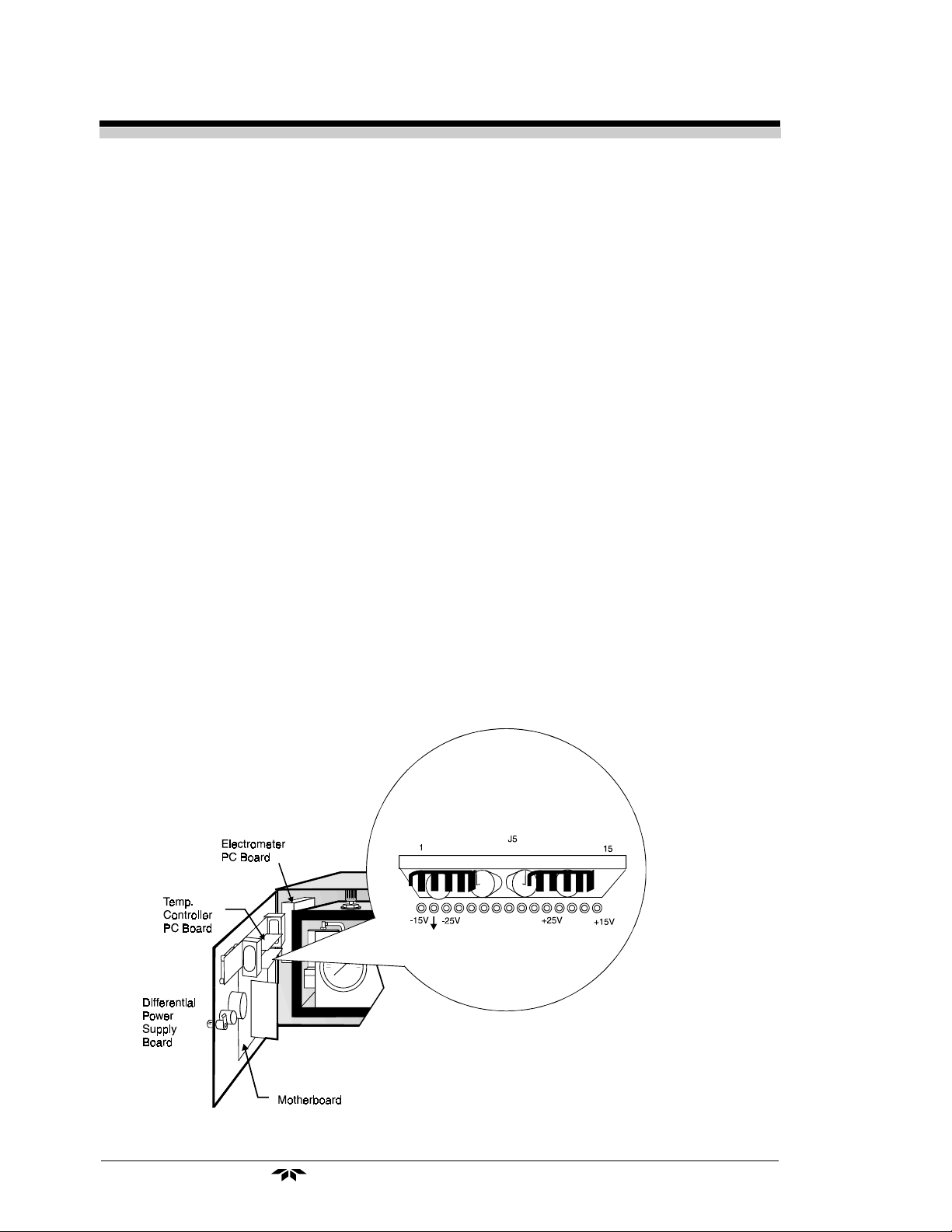
5.1.1 Loss of Zero Control
If the zero cannot be controlled as directed above, a failure has occurred in either the differential power supply or the electrometer-amplifier.
Use the following procedure to isolate the fault:
With a digital voltmeter (DVM) set to read 15 VDC, check the positive and negative 15 V output of the power supply as follows:
(See schematic and assembly drawings for the differential power
supply PC board. Additional information can be found in the printed
circuit board description section at the end of this chapter.)
1. Connect the negative voltmeter lead to the common (pin 2) and
the positive lead to pin 15 of connector J5. The measured
voltage should be 15±1 volt. See Figure 5-1.
2. Then connect the positive DVM lead to pin 1 of connector J5.
Measured voltage should be -15±1 volt.
If correct readings are not obtained at both points, the differential
power supply has failed, and the printed circuit card must be replaced. If
correct readings are noted, the electrometer-amplifier has failed, and that
printed circuit card must be replaced.
NOTE: TET/AI recommends that spares for each of the printed circuits be
kept on hand so that service can be restored immediately. The
faulty circuit card should be returned to the factory for repair.
Unless personnel knowledgeable in electronics are available, do not
tamper with the circuits.
5.1.2 Anode Voltage Check
If the output can be adjusted by the zero control (the above section,
step 2), the cell anode voltage should be verified as follows:
WARNING These procedures should be caried out only by suitably
trained personnel familiar with high voltage circuit
boards. The anode-igniter unit and associate circuitry
involve dangerously high voltages.
Refer to the cell wiring diagram. Using a voltmeter set to measure 299
VDC, check the voltage on terminal four on the terminal strip TS6 on the
(mother) PCB, as follows:
1. Connect the negative voltmeter lead to ground and the positive
lead to TS6 terminal 4. Be careful not to short the circuit by
touching both an electrode and the cell body simultaneously.
The reading obtained should be 250±22 VDC.
Teledyne Analytical Instruments
5-3
Page 38
Chapter 5 Model 402R-EU
2. Apply procedure given in Section 1, Page VI of this manual,
then unplug P3 from J3 of the anode-igniter cable.
3. Reconnect the mains (line) cord to the 402R-EU and turn it ON.
4. Measure the voltage between socket "3" of J3 and ground and
then reapply the same procedure as provided in section 1, page
VI of this manua.
5. If the voltage was 250±22VDC, then check the anode-ignitor
cable and the sensor for low electrical resistance to ground or
other problems. Else, if the voltage was not 250±22VDC, then
replace the flame guard and anode power supply Pc Board.
WARNING:Do not touch capacitor C1 or C2, resistor R1 or R2, di-
odes D1, ZD2 or ZD3 or their related circuit foils. A shock
hazard may exist. Note and follow the turn off procedure
given in
INTERNAL INACCESSIBLE SHOCK HAZARDS"
Section 1 Page VII: "PROCEDURE FOR REMOVAL OF
.
Carefully remove the circuit board without touching any connections
which might lead to C1 or C2. After removal, discharge the two capacitors
by placing a jumper wire across each.
3. The anode voltage may also disappear or be greatly diminished
when condensation inside the sensor has occurred, shorting the
ignitor to the sensor body across the wet insulator. This usually
occurs when the flame is turned on, if the sensor has not been
preheated for at least 1 hour.
5.1.3 Electronic Stability
If the checks outlined above indicate that conditions are normal, allow
the analyzer to run electronically with the collector cable disconnected for
several hours in the lowest range, and with the zero control adjusted so that
the recorder is reading midscale. If all is normal electronically, a noise-free
(pen width) recording, showing absolutely no instability, should be obtained for as long as the analyzer is allowed to run in this configuration. If
the recording obtained is noisy or erratic, replace the electrometer-amplifier PC board.
5.1.4 Printed Circuit Board Replacement
Whenever the differential power supply temperature controller or
electrometer-amplifier printed circuit boards are replaced (or repaired),
instrument performance should be rechecked. The replacement circuit
boards are tested and adjusted at the factory before they are sent, and in
most cases, no recalibration will be required.
Teledyne Analytical Instruments5-4
Page 39

Total Hydrocarbon Analyzer Maintenance and Troubleshooting
If performance is not adequate, then the analyzer must be
restandardized as described in Section 4-7: Calibration before being placed
back in service.
Whenever the flame guard and anode power supply printed circuit
board has been replaced, the flame guard circuit must be recalibrated (see
Section 5.3.1: Flame Guard Circuit Calibration) and the analyzer must be
restandardized.
If the instrument performs as outlined in this section, the problem is
not related to the measuring circuit electronics.
5.1.5 Collector Cable
Before reconnecting the collector cable, check the continuity of the
center wire of the cable with an ohmmeter by measuring between the
center pins at each plug on the lowest resistance scale of the meter. Flex
the cable while making this measurement to be sure that there is not an
intermittent open circuit. If there is, replace the cable. Do not attempt to
repair the cable, as special tooling is required to disassemble and reassemble the cable plugs.
5.2 Temperature Control Electronic Check
If the heating circuit fails, the output of the analyzer will tend to drift
with changes in ambient temperature. Such a failure will be more evident
in the low range. If the temperature environment surrounding the analyzer
is closely regulated, failure in this circuit might go unnoticed after the
initial failure. If the environment follows day and night temperature
changes, the analyzer will show a diurnal, bi-directional drift when operated on zero gas. The magnitude of the drift will be a function of the
temperature differential experienced by the analyzer. To check the circuit,
employ the following procedure:
Consult the 402R-EU schematic and assembly drawings, as well as
the temperature control PC board schematic and assembly drawings at the
rear of the manual for circuit details and component placement. See also
Figures 5-2 and 5-3 for the location of the Temperature Controller PC
Board.
1. An indicator light on the control panel cycles on and off with
the heating element; the light is on when the heater is on, and
vice versa. Failure of the light to come on at all when the cell
compartment is cold indicates a problem in the temperature
sensing or control circuitry or the wiring that interconnects the
Teledyne Analytical Instruments
5-5
Page 40

Chapter 5 Model 402R-EU
thermistor to the circuit. If the light stays on constantly, but the
compartment does not heat up, then a problem with the heating
element or connecting wiring is indicated.
2. Apply procedure for removal of internal inacessible shock
hazards, mentioned in section 1, page VI of this manual
3. Check the sensing thermistor by measuring the resistance
between its connecting wires. See Figure 5-2. Disconnect one of
the thermistor wires from terminal strip TS-2 (terminals 1 and
2) on the mother board and measure resistance between that
Figure 5-2: Identification and Location of Thermistor and Wires
Teledyne Analytical Instruments5-6
Page 41

Total Hydrocarbon Analyzer Maintenance and Troubleshooting
Figure 5-3: Motherboard
wire and the remaining undisturbed terminal. See Figure 5-3.
Resistance of the thermistor varies with its surrounding
temperature. A reading of between 10KΩ and 20KΩ at around
25 °C may be measured. (Under very cold conditions, the
resistance could be as high as 50KΩ; under hot conditions, just
a few thousand ohms.) If the thermistor measures anywhere in
this range, it is most likely OK. Otherwise, if the circuit is open,
check the wires leading to the thermistor.
4. Check the heating element by measuring its resistance.
Disconnect one of the heater wires from either terminal 3 or
terminal 4 of TS-2 on the motherboard which is shown in
Figure 5-3, and check the resistance between that wire and the
remaining undisturbed terminal. If a reading of 288Ω ±10% is
found, then the heating element is most likely OK. If an open
circuit is found, check the heater wires and a possible connector
between the heater and TS-2. If no problems are found, and the
heater circuit is open, then replace the heater element.
Teledyne Analytical Instruments
5-7
Page 42

Chapter 5 Model 402R-EU
NOTE: If any of the components located inside the isothermal chamber has
failed, the instrument must be removed for service. The sample
selector module can be unplugged for service. All other components can be reached without instrument removal.
5. If no problems are found with either the thermistor or the heater
circuits, then replace the temperature control board.
5.3 Ignition and/or Flame Guard Circuit Checks
If the flame guard circuit will not hold the flame-out lamp off when
the ignition procedure is employed (see Chapter 3: Flame Ignition), perform the following procedure to isolate the problem (consult the system
schematic for details of the circuit):
1. Disconnect connector J3 (4 sockets) from connector P3 (4
pins). These are one of the large pairs of connectors just outside of
and to the left of the isothermal chamber. See Figure 5-2.
2. Check the flame guard sensing thermistor by measuring the resis-
tance between pins 1 and 2 of P3. The nominal resistance at
25°C is 100K, resistance readings at about 25°C of greater than
250K or less than 40K indicate that the thermistor is defective and
should be replaced.
3. Check the anode-igniter coil for continuity by measuring
between pins 3 and 4 of the disconnected cable plug P3. The
ohmmeter should indicate a maximum resistance of 1Ω.
4. If either step 2 or 3 does not check as indicated, remove the
electrode assembly of the detection cell and return it to the
factory for repair. If the quartz flame tip is damaged, the top
section of the cell may be removed by disconnecting the vent
line, and removing the screws around its flange. Return the unit
complete with attached electrode cable. If steps 2 and 3 both
check out properly, reconnect the anode-igniter cable (connect
J3 to P3).
Teledyne Analytical Instruments5-8
Page 43

Total Hydrocarbon Analyzer Maintenance and Troubleshooting
5. Observe the K3 relay operation as the selector switch is moved
in and out of the IGNITE position (see Figure 5-3). If the relay
does not energize in the IGNITE position, remove it and check
it for an open coil (pins 13 and 14). The nominal resistance is
650Ω. If the coil checks OK, remove the flame guard power
supply board and check the forward and backward resistance of
its transient suppression diode by measuring pins 13 and 14 of
the relay socket. A multimeter should be set to the “diode test”
setting. The positive lead from the multimeter shall be
connected to socket number 13 on the relay socket and the
negative lead to socket 14. In this direction the multimeter
should indicate approx. 0.6 V and it should indicate an
overload when the lead connections are reversed. If these
readings are not obtained, then the diode (“D1” on the mother
PCB) must be replaced.
NOTE: If, after replacing a defective diode, the circuit still does not work
properly, the flame guard circuit components have been damaged,
and the flame guard PC board must be replaced.
6. If the preceding steps check out correctly, the flame guard
portion of the circuitry on the flame guard/anode power supply
PC board is either defective or needs recalibrating. Use the
following procedure to determine which problem exists:
IMPORTANT: If the circuit proves defective, the analyzer will have to be
restandardized (see Chapter 3: Stabilization Period) after the
board is replaced. (See section 5.1.4: Printed Circuit Board
Replacement.)
5.3.1 Flame Guard Circuit Calibration
1. With the selector switch in the high position, introduce span gas
into the sample path of the analyzer. Verify that all control
panel pressure readings are correct, and that the bypass flowrate
is 0.5 SCFH or greater.
2. Operate the selector switch in and out of the IGNITE position
until the presence of fuel is assured.
3. Observe the panel meter. If the meter reads up scale when the
selector switch is returned to the high position, ignition of the
Teledyne Analytical Instruments
5-9
Page 44

Chapter 5 Model 402R-EU
flame has occurred. If ignition failure is indicated (the meter
will read zero when the switch is in the high range), then refer
to Section 5.3: Ignition and/or Flame Guard Circuit Checks to
check the ignition circuit.
4. If ignition is verified, adjust the miniature potentiometer on the
flame guard anode power supply board until it is over 75% of
its travel clockwise (but not fully clockwise or counterclockwise), and repeat the ignition procedure. If the sensing
thermistor is intact (see step 2 under Section 5.3), and a fault
does not exist on the PC board, the flame guard circuit should
hold the flame-out indicator light in the off condition. If it does
not, replace the circuit board. If it does (or after a new board is
installed and the preceding steps completed), proceed with the
remaining steps of this section.
5. Turn the potentiometer slowly counter-clockwise until the
flame-out indicator light just comes on. Turn the potentiometer
gradually clockwise again (while repeating the ignition
procedure) until the light remains off. This adjusts the
sensitivity of the flame guard circuit. If properly adjusted, the
flame guard circuit should illuminate the flame-out indicator
light within 10-20 seconds after flame failure. This can be
easily tested by turning off the fuel and checking the light.
5.4 Sampling System
If the procedures outlined above do not correct the problem, the fault
must be related to the gas control systems. Plugged or faulty regulators,
plugged restrictors, or leaks within the system can cause erratic performance. TET/AI recommends that the factory or an authorized representative be contacted before attempting any repairs to the sample or supporting
gas systems within the analyzer.
5.5 Printed Circuit Board Descriptions
The electronics circuitry of the analyzer is designed with the latest
integrated circuit technology. The individual circuits which are required to
process the incoming signal and condition it to provide the various outputs,
alarms, indicators, etc., are built upon separate plug-in printed circuit
Teledyne Analytical Instruments5-10
Page 45

Total Hydrocarbon Analyzer Maintenance and Troubleshooting
boards and interconnected via a motherboard, which contains the connectors into which the circuit boards are inserted.
The layout of the motherboard changes very little, in spite of the fact
that it is used in a wide variety of instruments. This allows a universal
approach to its use, and the circuit boards which are used can thus remain
the same in varied applications.
The circuit board connectors on the Mother Board are labeled J1
through J6 and are used in totally standard instruments to connect and hold
plug-in printed circuit boards in the following configuration:
J1: Flame guard-anode power supply
J2: Not used for the standard Model 402R
J3: E-to-I converter (isolated)
J4: Alarm comparator (dual)
J5: Differential power supply
J6: Temperature control
In addition, connector J1 is used with the Model 402R-EU; J1 plugs
onto the electrometer amplifier PC board. These are shown in Figures 5-2
and 5-3.
The alarm comparator is an optional circuit; it has two (dual) adjustable setpoints at which an alarm or indicator is activated. Alarm circuits
normally employ relays to provide contacts which may be connected, via
terminal strip, to auxiliary signal devices.
Consult the following pages for detailed descriptions of the plug-in
circuits used with the Model 402R.
5.5.1 Flame Guard and Anode Power Supply Printed
Circuit Board
Schematic No. B-67810
Assembly Dwg. No. B-67797
Anode Power Supply: The high voltage anode power supply com-
ponents (except for transformer) are mounted on the flame guard and
anode power supply printed circuit board. High voltage regulation is
Teledyne Analytical Instruments
5-11
Page 46

Chapter 5 Model 402R-EU
achieved through the use of series-connected zener diodes. The simplicity
of this circuit’s design can be attributed to the extremely low current
demand of the anode circuit. The positive output voltage is nominally 250
volts. Output tolerance is ±22 volts from the specified 250 volts, due to
variation in components from unit to unit.
Flame Guard Circuit: A thermistor-controlled, transistorized
switching circuit is employed to operate a relay in the event of a flame-out
condition. A panel indicator light is turned on by the relay to alarm personnel that a flame-out condition has occurred.
The controlling thermistor is located within the upper section of the
sensor cell assembly. The electronic circuit components are mounted on
the same printed circuit board as the anode power supply. The relay is
located on the motherboard and the indicator light on the control panel.
The thermistor is located in the circuit so that it controls the bias on
the switching transistor. The circuit is factory set so that with the flame
burning, the bias on the transistor is such that it conducts and holds the K3
relay energized. When energized, the relay extinguishes the Flame Out
indicator light. Conversely, if the flame goes out, bias to the switching
transistor is lost, the relay drops out, and the Flame Out light receives
power through normally closed contacts.
During ignition, the flame heats the thermistor, holding the relay in
the energized condition and the indicator light off. If the Flame Out light
comes on as the switch returns from its momentary IGNITE position, then
the flame is not burning, and the ignition procedure must be repeated.
Millivolt Output Resistors: Resistors R5 and R6 on this PC board
are selected per application. They are used to convert the voltage signal
obtained from the wiper of the span potentiometer into an auxiliary millivolt output.
5.5.2 Regulated Differential Power Supply Printed
Circuit Board
Schematic No. B-33129
Assembly Dwg. No. A-9306
The purpose of this power supply circuit is to provide the DC voltage
requirements of the various electronic circuits within the analyzer or
system. An input voltage of 40-50 VAC at card pins 8 and 10 (centertapped to ground at pin 14) is converted to a non-regulated +24 VDC at pin
Teledyne Analytical Instruments5-12
Page 47

Total Hydrocarbon Analyzer Maintenance and Troubleshooting
12, -24 VDC (non-regulated) at pin 4, regulated +15 VDC at pin 15, and
regulated -15 VDC at pin 1.
The circuit board can be easily tested (by verifying the voltages while
in operation) as follows:
Regulated \15 volts:
1. Connect the negative voltmeter lead to the common (pin 2) and
the positive lead to pin 15 of the card connector. The measured
voltage should be 15±0.5 volt. Refer to Figure 5-1.
2. Then connect the positive DVM lead to pin 1 of the card
connector. Measured voltage should be -15±0.5 volt.
Non-regulated \24 volts:
1. With the negative lead of the DMM still connected to pin 2
(ground), connect the positive lead to pin 12, and verify 24
volts (nominal).
2. Then connect the positive lead to pin 4 and verify -24 volts
(nominal).
Input Voltage 40-50 VAC:
Using a voltmeter set to measure at least 50 VAC, test the voltage
between the circuit card pins 8 and 10; voltage should measure ca. 3050Vrms. Voltage from either pin 8 or pin 10 to ground should measure half
the voltage found across pins 8 and 10.
5.5.3 Proportional Temperature Controller Printed
Circuit Board
Schematic No. B-30974
Assembly Dwg. No. B-30868
The temperature of the chamber to be controlled is regulated by a
thermistor-directed electronic circuit. The thermistor and heating element
are located in the chamber, and the balance of the circuit components are
mounted on the temperature controller printed circuit board, which plugs
into a connector on the motherboard.
The control temperature is determined by the value of resistor R3 on
the temperature controller printed circuit board, selected (at the time of
Teledyne Analytical Instruments
5-13
Page 48

Chapter 5 Model 402R-EU
manufacture) from the chart on schematic B-30974 to provide the desired
control point.
The thermistor used in the circuit is a negative temperature coefficient
(NTC) device; as the chamber temperature increases, the resistance of the
thermistor decreases, and vice versa.
The resistance of the thermistor in the circuit is compared with the
value of resistor R3; when their resistance is equal, or when the resistance
of R3 is less than that of the thermistor, the heating circuit is activated.
When a temperature deficiency is sensed by the thermistor, integrated
circuit A1, acting as a zero-crossing switch, applies a pulsed signal to triac
Q1, which in turn applies full wave power to the heating element.
IC A1 employs a diode limiter, a zero-crossing (threshold) detector,
an on-off sensing amplifier (differential comparator), and a Darlington
output driver (thyristor gating circuit) to provide the basic switching
action. The DC operating voltages for these stages are provided by an
internal power supply, with resistor R1 and capacitor C1 added externally.
The on-off sensing amplifier in this circuit is configured as a freerunning multivibrator. This scheme adds proportional control, which takes
over when the comparator inputs are at the design differential voltage.
Initially, when cold, the thermistor resistance is large, and the voltage
at pin 13 is larger than that at pin 9. As the temperature of the controlled
chamber begins to rise, the resistance of the thermistor decreases, thus
reducing the voltage at pin 13. During this warm-up time the thyristor
gating circuit is continuously delivering gate current from pin 4, thus
maintaining constant fullwave AC power to the heater.
When the temperature reaches the selected control point, pin 13
voltage is about the same as pin 9 voltage, and proportional control takes
over. The rate at which thyristor (triac) Q1 conducts and allows power to
be delivered to the heater is determined by the combination of components
R2 & R3, R4, C3, R5, and the thermistor resistance at the control temperature. Consequently, the balance point of the bridge formed by this combination of components can be altered by the selection of R3, causing the
circuit to seek a temperature at which the thermistor resistance balances the
bridge.
Because IC A1 triggers the thyristor at zero-voltage points in the
supply voltage cycle, transient load current surges and radio frequency
interference (RFI) are substantially reduced. In addition, use of the zerovoltage-switch reduces the rate of change of on-state current (di/dt) in the
thyristor.
Teledyne Analytical Instruments5-14
Page 49

Total Hydrocarbon Analyzer Maintenance and Troubleshooting
5.5.4 Electrometer-Amplifier PC Board
Schematic No. B-34436
Assembly Dwg. No. C-34434
The ions formed in the process of burning hydrogen in the presence of
hydrocarbon components of the sample gas cause an electrical conduction
between two electrodes in the combustion chamber (or detector cell) that is
amplified by a high sensitivity and high input impedance electrometeramplifier circuit. The electrical output of the electrometer-amplifier is
directly proportional to the quantity of flame ionizable hydrocarbons
present.
The electrometer amplifier PC board is not located on the
motherboard, as are the other plug-in printed circuit boards; rather, it is
mounted to the backplate assembly and interconnected to the electronics
circuitry by means of a single card edge connector, so that the ease of
replacement of a plug-in board is maintained. The high input impedance
requires a shield, or cover, which is removable for access, as well as a
shielded input conductor. Interconnection with the collector is made by a
coaxial cable. Although the cable and fittings are intended for coaxial
service, the cable is actually being used as a shielded single-conductor
connection. The collector cable plugs into a coaxial connector on the
electrometer amplifier PC board, which is located at the rear cover.
The circuit consists of an electrometer amplifier and an operational
amplifier. It is a very high-gain, current-to-voltage converter circuit,
having an input impedance measuring in the billions of ohms. It is static
sensitive and highly susceptible to contamination, and special handling
precautions must be taken.
Because of its high impedance, the input circuitry to the electrometer
has had careful design consideration. The glass resistors (R2 and R3) in the
input gain circuit (see schematic) are installed on Teflon-insulated standoffs, instead of directly to the printed circuit, to eliminate the possibility of
leakage currents.
To eliminate any possibility of contamination of the insulating materials employed, the completed PC board is ultrasonically cleaned in laboratory grade alcohol. Under no circumstances should the parts described
be handled with bare fingers. A freshly-scrubbed finger, stroked along
Teledyne Analytical Instruments
5-15
Page 50

Chapter 5 Model 402R-EU
one of the glass resistors, would deposit enough skin oil to completely
upset the range division of the attenuator circuit.
Resistor R3 is a 1000MΩ resistor used in the feedback circuit of the
amplifier. R2 has a resistance of 100,000MΩ and is used in series with the
zero potentiometer slider. This circuit is used to nullify any offset signal
introduced by the signal electrode. Trimmer P1 is used to nullify the offset
signal generated by the electrometer amplifier.
The output of the circuit is standardized against gases with known
hydrocarbon concentrations by setting the zero and span control potentiometers, located on the door, so that the meter and/or recorder indicates the
hydrocarbon concentration of the gas being used.
The positive and negative operating voltage required by the electrometer amplifier is furnished by a regulated differential power supply circuit,
a plug-in printed circuit board which plugs into a connector on the
motherboard.
The stability of the electrometer circuit can be tested as follows:
1. Disconnect the collector cable.
2. Turn the span control about midway between clockwise and
counter-clockwise.
3. Place the selector switch in the low range position.
4. Offset the zero control so that the recorder reads at some
point upscale, and record a 24 hour chart.
Electrometer-Amplifier PC Board Adjustments:
1. Input Zero Adjustment:Connect DMM (millivolt range)
between ground and the wiper of the zero potentiometer. Adjust
the zero pot until the DMM reads zero.
2. Absolute Zero Adjustment: Disconnect the input cable
from the tower (sensor assembly). With zero millivolts input to
the circuit, open the plug of P1 trimmer on the electrometeramplifier cover. Using a DMM, measure the the signal between
the clockwise terminal of the span pot and ground, and adjust
P1 in the electrometer-amplifier board to obtain zero reading on
the DMM.
The electrometer-amplifier circuit is now nulled.
Teledyne Analytical Instruments5-16
Page 51

Total Hydrocarbon Analyzer Maintenance and Troubleshooting
5.5.5 Comparator Alarm Printed Circuit Board
Schematic No. B-33128
Assembly Dwg. No. A-9309 (dual)
The comparator alarm circuit consists simply of an operational amplifier used to turn a transistor on or off according to logic wiring, in response
to an increasing process signal. The transistor, in turn, in its “turned on”
state, activates a contact relay to provide switching contacts accessible at
the interconnection terminal strip.
For the number 1 alarm circuit, potentiometer P3 sets a reference
voltage at strapping point B on the circuit board. The process signal is
present at strapping point A. Depending upon the strapping configuration
(jumper placement), IC A1 can be used in its inverting or non-inverting
mode to control relay K1 by means of NPN transistor Q2.
When in its inverting mode (jumpers JP3 and JP4 installed), A1
receives the positive signal voltage at its inverting input (pin 2) and the
positive reference voltage at its non-inverting input (pin 3). When the
voltage at pin 2 is more positive than that at pin 3, A1’s output goes low
(negative), and the transistor is turned off, de-energizing relay K1. Thus,
K1 is energized when the signal is below the point set by P3 (Alarm
setpoint 1) and de-energized above the setpoint.
In its non-inverting mode (jumpers JP1 and JP2 installed), A1
switches to a negative output when the signal voltage (now applied to pin
3) is less than the reference voltage (pin 2), to a positive output if the
signal output is greater, and vice versa. Once again, when A1’s output is
positive, Q2 is turned on, energizing K1; negative A1 output turns off Q2,
de-energizing K1. Thus configured, the alarm relay is energized “above
setpoint”, or when the signal is greater than the reference.
For number 2 alarm circuits, setpoint potentiometer P4 is used to
adjust alarm setpoint #2. IC A2, transistor (PNP) Q4, and alarm relay K2
are added to make up the second alarm. Transistor Q4 (PNP) acts in the
reverse manner from Q2 (NPN), turning on with a negative A2 output, off
with positive. Installing jumpers JP7 and JP8 configures the second alarm
to energize below alarm 2 setpoint (P4), and installed jumpers JP5 and JP6
causes the alarm to energize above setpoint.
Teledyne Analytical Instruments
5-17
Page 52

Chapter 5 Model 402R-EU
Teledyne Analytical Instruments5-18
Page 53

Total Hydrocarbon Analyzer Appendix
IF USED OUTSIDE OF THESE SPECIFICATIONS
THE INSTRUMENT MAY BE DAMAGED AND
HAZARDOUS CONDITIONS MAY BE PRODUCED.
Appendix
Specifications
Ranges: 0-10, 0-100, 0-1000ppm hydrocarbon stan-
dard (methane equivalent)
(0-1ppm low range is optional.)
Sensitivity: 1% of full scale
Accuracy: ±2% of full scale at constant temperature
(Applies to standard ranges.)
Response Time: 90% in less than 15 second
Operating Temperature: 41°F to 110°F (5°C to 43.3°C)
Fuel: Mixture of 40% hydrogen, 60% nitrogen
recommended
(Other mixtures are possible. Contact TET/AI
for applications assistance.)
Sensor Type: Flame Ionization Detector with Flame Guard
Signal Output: Internal - Digital Panel Meter
External - 0-1VDC, 4-20mA DC Isolated
Power Requirement: 115VAC ± 10% 50/60 Hz
230VAC ± 10% 50/60Hz
90VA nominal, 150VA maximum
Enclosure: 19" (48.3cm) Rack-Mounted Steel Enclosure
19" (48.3cm) W x 8.75" (22.2cm) H x 15.5"
(39.4cm) D
Teledyne Analytical Instruments
A-1
Page 54

Appendix Model 402R-EU
Application Data
Model Number:
Serial Number:
Ranges Of Analysis:
Output Signal:
Start-Up Span Setting:
Control Panel Pressure Settings:
Comments:
Blanket Air:
Fuel:
Sample:
Bypass Flowrate: A minimum of 0.25 SCFH is indicated on
the integral flowmeter
Recommended Support Gases: The accessory gases should all be laboratory
analyzed and certified as to their hydrocarbon content.
Blanket Air: Water pumped, hydrocarbon free, com-
pressed air.
Fuel: A hydrocarbon-free composition of 40%
hydrogen and 60% nitrogen.
Zero Gas: Water pumped, hydrocarbon free (certified)
Span Gas: _______ppm methane in ______ (certified)
The span gas contains a known amount of methane impurity. The span
gas must be certified as to its methane equivalent impurity.
IMPORTANT: For the best possible results, zero and span gases that are
representative of the parent (or background) gas should
always be used.
This is particularly true in applications where the analyzer is being used
to analyze a number of different samples with varying concentrations of
oxygen. The geometry and temperature of the flame will be somewhat
dependent on the oxygen content of the sample. Alterations in the flame
configuration will lead to differences in output readings. The application
calls for this analyzer to be used on oxygen, air, and a composition of oxygen and nitrogen. For the best possible results, TAI recommends that zero
and span gases representative of each of these samples be used to standardize
the analyzer.
Teledyne Analytical InstrumentsA-2
Page 55

Total Hydrocarbon Analyzer Appendix
Recommended Spare Parts List
Qty. P/N Description
1 B67797 PC board, Flame guard & anode power supply
1 C34434 PC board, Electrometer-amplifier
1 B30868 PC board, Temperature control
1 A9306 PC board, Differential power supply
1 B29600 PC board, E/I Converter (isolated)
1* A10045 PC board, Alarm comparator (single)
1* A9309 PC board, Alarm comparator (dual)
1 A46128 Coaxial cable
1 R179 Relay
1 L79 Lamp, neon
6 F1361 Fuse, 1.6A, Littelfuse P/N 21501.6, only used for
F1, F2 and F3.
4 F1358 Fuse 0.5A, Littelfuse P/N 218:500 only, used for F5
4 F1375 Fuse 0.8A, Littelfuse P/N 218.800 only, used for F6,
and used for 230VAC version.
4 F1378 Fuse 0.2A, Littelfuse P/N 218.200, only used for F4,
and used for 115VAC version only.
4 F1374 Fuse 0.1-5A, Littelfuse P/N 218.125 only, used for
F4, and used for 230VAC version only.
1 L156 Lens, red
1 L154 LED, red
1 A33748 Thermistor assembly
* Optional—will not be present if not specified at time of order.
A minium charge of US $20.00 is applicable to spare parts orders.
IMPORTANT: Orders for replacement parts should include the part number
and the model and serial number of the system for which the
parts are intended.
Send orders to:
Teledyne Electronic Technologies
Analytical Instruments
16830 Chestnut Street
City of Industry, CA 91749-1580
Telephone: (626) 934-1500
TWX: (910) 584-1887 TDYANYL COID
Fax: (626) 961-2538
Web: www.teledyne-ai.com
or your local representative
Teledyne Analytical Instruments
A-3
Page 56

Appendix Model 402R-EU
Drawing List
C-66897 Outline diagram
B-67695 Input-output diagram
B-67698 Piping diagram
B-67691 Gas connection diagram w/sample select module (optional)
B-67692 Gas connection diagram w/o sample select module (optional)
D-67924 Schematic, 402R, 19" rack standard
B-34436 Schematic, Electrometer PC board
B-67810 Schematic, Flame guard, anode power supply PC board
B-33129 Schematic, Power supply PC board
B-30974 Schematic, Temp. controller PC board
B-29602 Schematic, E to I converter, isolated
B-33128 Schematic, Alarm PC board (optional)
B-34609 Schematic, digital meter, 2½ digit standard
D-67923 Wiring diagram, 19" rack standard
Assemblies
D-68011A,B,C,D Assembly, gas control module
D-67685 Assembly, door (115V version)
D-67809 Assembly, sensor
B-68234 Assembly, sensor plug
A-46128 Assembly, signal cable
B-67881 Cable Assembly, heater
PC Board Assemblies
C-67789 PCB Assy, motherboard, basic
C-34468 PCB Assy, motherboard, 402DPM (version)
B-67797 PCB Assy, anode power supply, flame guard
A-9306 PCB Assy, power supply
A-9309 PCB Assy, alarms (optional)
B-29600 PCB Assy, E to I converter, isolated
B-30868 PCB Assy, temperature controller, 110V
C-34434 PCB Assy, electrometer
B-34592 PCB Assy, digital meter, standard, 2½ digit
Teledyne Analytical InstrumentsA-4
 Loading...