

Teledyne 3700 Installation And Operation Manual
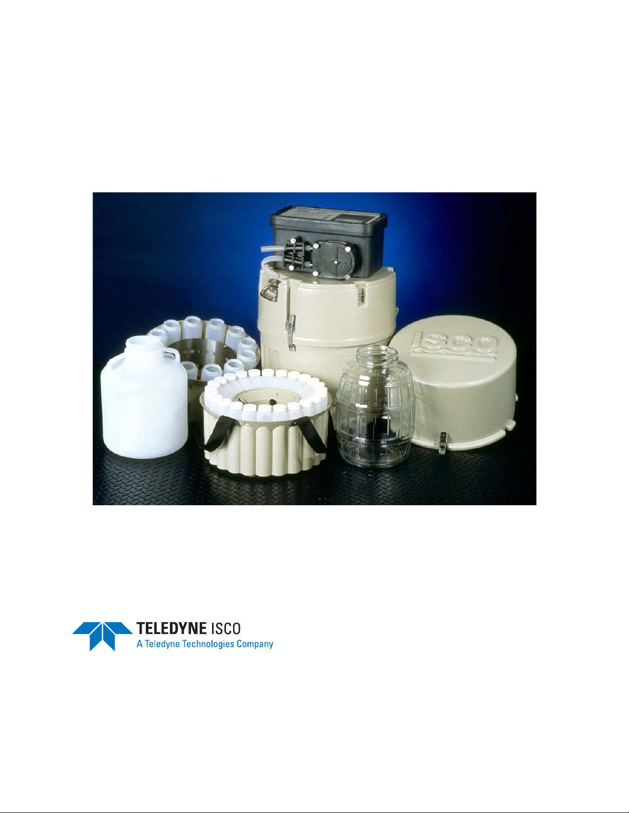
3700 Portable Samplers
Installation and Operation Guide
Part #60-3703-267 of Assembly #60-3704-101
Copyright © 1994. All rights reserved, Teledyne Isco, Inc.
Revision GG, August 8, 2008


Foreword
This instruction manual is designed to help you gain a thorough understanding of the
operation of the equipment. Teledyne Isco recommends that you read this manual
completely before placing the equipment in service.
Although Teledyne Isco designs reliability into all equipment, there is always the possibility of a malfunction. This manual may help in diagnosing and repairing the malfunction.
If the problem persists, call or e-mail the Teledyne Isco Technical Service Department
for assistance. Simple difficulties can often be diagnosed over the phone.
If it is necessary to return the equipment to the factory for service, please follow the
shipping instructions provided by the Customer Service Department, including the
use of the Return Authorization Number specified. Be sure to include a note
describing the malfunction. This will aid in the prompt repair and return of the
equipment.
Teledyne Isco welcomes suggestions that would improve the information presented in
this manual or enhance the operation of the equipment itself.
Teledyne Isco is continually improving its products and reserves the right to
change product specifications, replacement parts, schematics, and instructions without notice.
Customer Service
Phone: (800) 228-4373 (USA, Canada, Mexico)
Fax: (402) 465-3022
Email: IscoCSR@teledyne.com
Technical Service
Phone: (800) 775-2965 (Analytical)
Email: IscoService@teledyne.com
Return equipment to: 4700 Superior Street, Lincoln, NE 68504-1398
Other Correspondence
Mail to: P.O. Box 82531, Lincoln, NE 68501-2531
Email: IscoInfo@teledyne.com
Web site: www.isco.com
Contact Information
(402) 464-0231 (Outside North America)
(800) 228-4373 (Samplers and Flow Meters)
Revised September 15, 2005

3700 Portable Samplers
Safety
3700 Portable Samplers
Safety
General Warnings Before installing, operating, or maintaining this equipment, it is
imperative that all hazards and preventive measures are fully
understood. While specific hazards may vary according to
location and application, take heed in the following general
warnings:
WARNING
This instrument has not been certified for use in
“hazardous locations” as defined by the National Electrical
Code.
WARNING
Avoid hazardous practices! If you use this instrument in
any way not specified in this manual, the protection
provided by the instrument may be impaired; this will
increase your risk of injury.
AVERTISSEMENT
Éviter les usages périlleux! Si vous utilisez cet instrument
d’une manière autre que celles qui sont specifiées dans ce
manuel, la protection fournie de l’instrument peut être
affaiblie; cela augmentera votre risque de blessure.
Additional safety information can be found in Appendix C.
Hazard Severity Levels This manual applies Hazard Severity Levels to the safety alerts,
These three levels are described in the sample alerts below.
CAUTION
Cautions identify a potential hazard, which if not avoided, may
result in minor or moderate injury. This category can also warn
you of unsafe practices, or conditions that may cause property
damage.
WARNING
Warnings identify a potentially hazardous condition, which
if not avoided, could result in death or serious injury.
DANGER
DANGER – limited to the most extreme situations
to identify an imminent hazard, which if not
avoided, will result in death or serious injury.
iii
3700 Portable Samplers
Safety
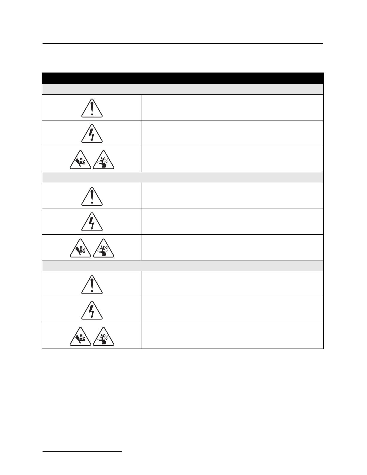
Hazard Symbols The equipment and this manual use symbols used to warn of
hazards. The symbols are explained below.
Hazard Symbols
Warnings and Cautions
The exclamation point within the triangle is a warning sign alerting you of
important instructions in the instrument’s technical reference manual.
The lightning flash and arrowhead within the triangle is a warning sign alerting you of “dangerous voltage” inside the product.
Pinch point. These symbols warn you that your fingers or hands will be seriously injured if you place them between the moving parts of the mechanism
near these symbols.
Symboles de sécurité
Ce symbole signale l’existence d’instructions importantes relatives au produit dans ce manuel.
Warnungen und Vorsichtshinweise
Ce symbole signale la présence d’un danger d’électocution.
Risque de pincement. Ces symboles vous avertit que les mains ou les
doigts seront blessés sérieusement si vous les mettez entre les éléments
en mouvement du mécanisme près de ces symboles
Das Ausrufezeichen in Dreieck ist ein Warnzeichen, das Sie darauf
aufmerksam macht, daß wichtige Anleitungen zu diesem Handbuch
gehören.
Der gepfeilte Blitz im Dreieck ist ein Warnzeichen, das Sei vor “gefährlichen
Spannungen” im Inneren des Produkts warnt.
Vorsicht Quetschgefahr! Dieses Symbol warnt vor einer unmittelbar drohenden Verletzungsgefahr für Finger und Hände, wenn diese zwischen die
beweglichen Teile des gekennzeichneten Gerätes geraten.
iv

3700 Portable Samplers
Table of Contents
Section 1 Introduction
1.1 Introduction. . . . . . . . . . . . . . . . . . . . . . . . . . . . . . . . . . . . . . . . . . . . . . . . . . . . . . . . 1-1
1.1.1 3700 Standard Description . . . . . . . . . . . . . . . . . . . . . . . . . . . . . . . . . . . . . . 1-1
1.1.2 3700 Compact Description . . . . . . . . . . . . . . . . . . . . . . . . . . . . . . . . . . . . . . . 1-2
1.2 Programmable Features . . . . . . . . . . . . . . . . . . . . . . . . . . . . . . . . . . . . . . . . . . . . . . 1-2
1.2.1 Flexible Sampling Intervals . . . . . . . . . . . . . . . . . . . . . . . . . . . . . . . . . . . . . 1-3
1.2.2 Multiplexing . . . . . . . . . . . . . . . . . . . . . . . . . . . . . . . . . . . . . . . . . . . . . . . . . . 1-3
STORM Sampling . . . . . . . . . . . . . . . . . . . . . . . . . . . . . . . . . . . . . . . 1-4
1.2.3
1.2.4 Master/Slave Sampling . . . . . . . . . . . . . . . . . . . . . . . . . . . . . . . . . . . . . . . . . 1-5
1.2.5 Accurate Sample Volumes . . . . . . . . . . . . . . . . . . . . . . . . . . . . . . . . . . . . . . . 1-5
1.2.6 Flexible Start Times . . . . . . . . . . . . . . . . . . . . . . . . . . . . . . . . . . . . . . . . . . . 1-5
1.2.7 Foreign Languages and Metric Units of Measure . . . . . . . . . . . . . . . . . . . . 1-6
1.3 Delivery System . . . . . . . . . . . . . . . . . . . . . . . . . . . . . . . . . . . . . . . . . . . . . . . . . . . . 1-6
1.3.1 Liquid Detector . . . . . . . . . . . . . . . . . . . . . . . . . . . . . . . . . . . . . . . . . . . . . . . 1-6
1.3.2 Pump Tubing and Suction Lines . . . . . . . . . . . . . . . . . . . . . . . . . . . . . . . . . . 1-6
1.3.3 Strainers . . . . . . . . . . . . . . . . . . . . . . . . . . . . . . . . . . . . . . . . . . . . . . . . . . . . . 1-7
1.3.4 Bottle Configurations . . . . . . . . . . . . . . . . . . . . . . . . . . . . . . . . . . . . . . . . . . 1-7
1.4 Power Options . . . . . . . . . . . . . . . . . . . . . . . . . . . . . . . . . . . . . . . . . . . . . . . . . . . . . . 1-8
1.5 Compatible Equipment . . . . . . . . . . . . . . . . . . . . . . . . . . . . . . . . . . . . . . . . . . . . . . . 1-8
1.5.1 Isco Flow Meters . . . . . . . . . . . . . . . . . . . . . . . . . . . . . . . . . . . . . . . . . . . . . . 1-8
1.5.2 Non-Isco Flow Meters . . . . . . . . . . . . . . . . . . . . . . . . . . . . . . . . . . . . . . . . . . 1-9
1.5.3 Samplink for Sampling Data Retrieval . . . . . . . . . . . . . . . . . . . . . . . . . . . . 1-9
1.5.4 Liquid Level Actuator . . . . . . . . . . . . . . . . . . . . . . . . . . . . . . . . . . . . . . . . . 1-10
1.5.5 Master/Slave Cables . . . . . . . . . . . . . . . . . . . . . . . . . . . . . . . . . . . . . . . . . . 1-10
1.6 Technical Specifications . . . . . . . . . . . . . . . . . . . . . . . . . . . . . . . . . . . . . . . . . . . . . 1-10
Section 2 Setup Procedures
2.1 Assembly and Disassembly of the Case . . . . . . . . . . . . . . . . . . . . . . . . . . . . . . . . . . 2-1
2.2 Preparing the Base Section . . . . . . . . . . . . . . . . . . . . . . . . . . . . . . . . . . . . . . . . . . . 2-1
2.2.1 Standard Base Section . . . . . . . . . . . . . . . . . . . . . . . . . . . . . . . . . . . . . . . . . . 2-1
2.2.2 Compact Base Section . . . . . . . . . . . . . . . . . . . . . . . . . . . . . . . . . . . . . . . . . . 2-1
2.2.3 Bottles . . . . . . . . . . . . . . . . . . . . . . . . . . . . . . . . . . . . . . . . . . . . . . . . . . . . . . . 2-2
2.3 Cooling the Samples . . . . . . . . . . . . . . . . . . . . . . . . . . . . . . . . . . . . . . . . . . . . . . . . . 2-2
2.4 Suction Line. . . . . . . . . . . . . . . . . . . . . . . . . . . . . . . . . . . . . . . . . . . . . . . . . . . . . . . . 2-2
2.4.1 Attaching Vinyl Suction Line . . . . . . . . . . . . . . . . . . . . . . . . . . . . . . . . . . . . 2-3
2.4.2 Attaching PTFE Suction Line . . . . . . . . . . . . . . . . . . . . . . . . . . . . . . . . . . . . 2-4
2.4.3 Routing of the Suction Line . . . . . . . . . . . . . . . . . . . . . . . . . . . . . . . . . . . . . . 2-4
2.5 Strainers . . . . . . . . . . . . . . . . . . . . . . . . . . . . . . . . . . . . . . . . . . . . . . . . . . . . . . . . . . 2-4
2.5.1 Intake Placement . . . . . . . . . . . . . . . . . . . . . . . . . . . . . . . . . . . . . . . . . . . . . . 2-5
2.6 Connection to Power Source . . . . . . . . . . . . . . . . . . . . . . . . . . . . . . . . . . . . . . . . . . . 2-5
2.7 Placement of the Sampler into Operation . . . . . . . . . . . . . . . . . . . . . . . . . . . . . . . . 2-6
2.7.1 Connection to a Flow Meter . . . . . . . . . . . . . . . . . . . . . . . . . . . . . . . . . . . . . 2-7
2.7.2 Saving Program Settings . . . . . . . . . . . . . . . . . . . . . . . . . . . . . . . . . . . . . . . . 2-7
2.8 Recovering the Sampler . . . . . . . . . . . . . . . . . . . . . . . . . . . . . . . . . . . . . . . . . . . . . . 2-7
2.8.1 Exchanging Sampler Tubs . . . . . . . . . . . . . . . . . . . . . . . . . . . . . . . . . . . . . . 2-7
2.8.2 Restarting . . . . . . . . . . . . . . . . . . . . . . . . . . . . . . . . . . . . . . . . . . . . . . . . . . . . 2-7
2.9 Sampler Locking . . . . . . . . . . . . . . . . . . . . . . . . . . . . . . . . . . . . . . . . . . . . . . . . . . . . 2-7
v

3700 Portable Samplers
Table of Contents
Section 3 Programming Guidelines
3.1 Description of Sampling Operation . . . . . . . . . . . . . . . . . . . . . . . . . . . . . . . . . . . . . 3-2
3.1.1 Sample Events and the Sampling Cycle . . . . . . . . . . . . . . . . . . . . . . . . . . . . 3-2
3.2 Types of Samples. . . . . . . . . . . . . . . . . . . . . . . . . . . . . . . . . . . . . . . . . . . . . . . . . . . . 3-2
3.2.1 Types of Sample Pacing . . . . . . . . . . . . . . . . . . . . . . . . . . . . . . . . . . . . . . . . . 3-3
3.2.2 Types of Sample Distribution . . . . . . . . . . . . . . . . . . . . . . . . . . . . . . . . . . . . 3-3
3.3 Types of Sampling Available in Extended Programming Mode. . . . . . . . . . . . . . . 3-6
3.3.1 Nonuniform Time Intervals . . . . . . . . . . . . . . . . . . . . . . . . . . . . . . . . . . . . . 3-6
3.3.2 Extended Multiplexing . . . . . . . . . . . . . . . . . . . . . . . . . . . . . . . . . . . . . . . . . 3-6
3.3.3 Multiple-Bottle Compositing . . . . . . . . . . . . . . . . . . . . . . . . . . . . . . . . . . . . . 3-7
3.3.4 Stops and Resumes . . . . . . . . . . . . . . . . . . . . . . . . . . . . . . . . . . . . . . . . . . . . 3-7
3.4 Stormwater Sampling. . . . . . . . . . . . . . . . . . . . . . . . . . . . . . . . . . . . . . . . . . . . . . . . 3-7
3.4.1 Storm-Event Sample Distribution Schemes . . . . . . . . . . . . . . . . . . . . . . . . 3-8
3.5 Programming Introduction. . . . . . . . . . . . . . . . . . . . . . . . . . . . . . . . . . . . . . . . . . . . 3-8
3.5.1 Operating States . . . . . . . . . . . . . . . . . . . . . . . . . . . . . . . . . . . . . . . . . . . . . . 3-8
3.5.2 Programming Modes . . . . . . . . . . . . . . . . . . . . . . . . . . . . . . . . . . . . . . . . . . . 3-9
3.5.3 Configure Sequence . . . . . . . . . . . . . . . . . . . . . . . . . . . . . . . . . . . . . . . . . . . 3-12
3.6 Programming Procedure. . . . . . . . . . . . . . . . . . . . . . . . . . . . . . . . . . . . . . . . . . . . . 3-12
3.6.1 Following Display Cues . . . . . . . . . . . . . . . . . . . . . . . . . . . . . . . . . . . . . . . . 3-13
3.6.2 Keypad Description . . . . . . . . . . . . . . . . . . . . . . . . . . . . . . . . . . . . . . . . . . . 3-13
3.6.3 Displays . . . . . . . . . . . . . . . . . . . . . . . . . . . . . . . . . . . . . . . . . . . . . . . . . . . . 3-16
3.7 Programming Examples . . . . . . . . . . . . . . . . . . . . . . . . . . . . . . . . . . . . . . . . . . . . . 3-18
3.8 Basic Programming Procedure. . . . . . . . . . . . . . . . . . . . . . . . . . . . . . . . . . . . . . . . 3-21
3.9 Configure Sequence. . . . . . . . . . . . . . . . . . . . . . . . . . . . . . . . . . . . . . . . . . . . . . . . . 3-38
3.9.1 Set Clock . . . . . . . . . . . . . . . . . . . . . . . . . . . . . . . . . . . . . . . . . . . . . . . . . . . . 3-38
3.9.2 Bottles and Sizes . . . . . . . . . . . . . . . . . . . . . . . . . . . . . . . . . . . . . . . . . . . . . 3-38
3.9.3 Portable or Refrigerated Sampler . . . . . . . . . . . . . . . . . . . . . . . . . . . . . . . . 3-39
3.9.4 Suction Line . . . . . . . . . . . . . . . . . . . . . . . . . . . . . . . . . . . . . . . . . . . . . . . . . 3-40
3.9.5 Liquid Detector . . . . . . . . . . . . . . . . . . . . . . . . . . . . . . . . . . . . . . . . . . . . . . 3-41
3.9.6 Programming Mode . . . . . . . . . . . . . . . . . . . . . . . . . . . . . . . . . . . . . . . . . . . 3-42
3.9.7 Load Stored Program . . . . . . . . . . . . . . . . . . . . . . . . . . . . . . . . . . . . . . . . . . 3-44
3.9.8 Save Current Program . . . . . . . . . . . . . . . . . . . . . . . . . . . . . . . . . . . . . . . . 3-45
3.9.9 Flow-Mode Sampling . . . . . . . . . . . . . . . . . . . . . . . . . . . . . . . . . . . . . . . . . . 3-46
3.9.10 Nonuniform Time . . . . . . . . . . . . . . . . . . . . . . . . . . . . . . . . . . . . . . . . . . . . 3-47
3.9.11 Calibrate Sampler . . . . . . . . . . . . . . . . . . . . . . . . . . . . . . . . . . . . . . . . . . . 3-47
3.9.12 Sampling Stop/Resume . . . . . . . . . . . . . . . . . . . . . . . . . . . . . . . . . . . . . . . 3-47
3.9.13 Start Time Delay . . . . . . . . . . . . . . . . . . . . . . . . . . . . . . . . . . . . . . . . . . . . 3-47
3.9.14 Enable Pin . . . . . . . . . . . . . . . . . . . . . . . . . . . . . . . . . . . . . . . . . . . . . . . . . 3-48
3.9.15 Event Mark . . . . . . . . . . . . . . . . . . . . . . . . . . . . . . . . . . . . . . . . . . . . . . . . 3-50
3.9.16 Purge Counts . . . . . . . . . . . . . . . . . . . . . . . . . . . . . . . . . . . . . . . . . . . . . . . 3-52
3.9.17 Tubing Life . . . . . . . . . . . . . . . . . . . . . . . . . . . . . . . . . . . . . . . . . . . . . . . . . 3-52
3.9.18 Program Lock . . . . . . . . . . . . . . . . . . . . . . . . . . . . . . . . . . . . . . . . . . . . . . . 3-52
3.9.19 Sampler ID . . . . . . . . . . . . . . . . . . . . . . . . . . . . . . . . . . . . . . . . . . . . . . . . . 3-52
3.9.20 Run Diagnostics . . . . . . . . . . . . . . . . . . . . . . . . . . . . . . . . . . . . . . . . . . . . . 3-52
3.9.21 Exit Configuration . . . . . . . . . . . . . . . . . . . . . . . . . . . . . . . . . . . . . . . . . . . 3-53
3.10 Extended Programming Mode . . . . . . . . . . . . . . . . . . . . . . . . . . . . . . . . . . . . . . . 3-56
3.10.1 Extended Mode Sample Pacing . . . . . . . . . . . . . . . . . . . . . . . . . . . . . . . . . 3-57
3.10.2 Extended Mode Sample Distribution . . . . . . . . . . . . . . . . . . . . . . . . . . . . 3-57
3.10.3 Extended Mode Sample Volumes . . . . . . . . . . . . . . . . . . . . . . . . . . . . . . . 3-58
3.10.4 Extended Mode Key Times . . . . . . . . . . . . . . . . . . . . . . . . . . . . . . . . . . . . 3-58
3.10.5 Sampling Stop/Resume . . . . . . . . . . . . . . . . . . . . . . . . . . . . . . . . . . . . . . . 3-62
3.11 Start Times . . . . . . . . . . . . . . . . . . . . . . . . . . . . . . . . . . . . . . . . . . . . . . . . . . . . . . 3-62
3.11.1 Events Preceding Sampling Routine . . . . . . . . . . . . . . . . . . . . . . . . . . . . 3-62
3.11.2 Nonuniform Times and Disable Signals . . . . . . . . . . . . . . . . . . . . . . . . . . 3-64
3.11.3 Manual Sample Key and Programmed Start Times . . . . . . . . . . . . . . . . 3-64
3.12 Stormwater Sampling. . . . . . . . . . . . . . . . . . . . . . . . . . . . . . . . . . . . . . . . . . . . . . 3-67
3.12.1 Storm Sampling Checklist . . . . . . . . . . . . . . . . . . . . . . . . . . . . . . . . . . . . . 3-67
3.13 Programming the Sampler for a Storm Routine . . . . . . . . . . . . . . . . . . . . . . . . . 3-71
vi

3700 Portable Samplers
Table of Contents
3.13.1 First Section: First Bottle Group Settings . . . . . . . . . . . . . . . . . . . . . . . . 3-71
3.13.2 Second Section: Second Bottle Group . . . . . . . . . . . . . . . . . . . . . . . . . . . . 3-74
3.14 Foreign Languages and Metric Units of Measure. . . . . . . . . . . . . . . . . . . . . . . . 3-79
3.15 Extended Programming Examples. . . . . . . . . . . . . . . . . . . . . . . . . . . . . . . . . . . . 3-80
3.16 Standby State . . . . . . . . . . . . . . . . . . . . . . . . . . . . . . . . . . . . . . . . . . . . . . . . . . . . 3-97
3.16.1 Operable Keys in Standby State . . . . . . . . . . . . . . . . . . . . . . . . . . . . . . . . 3-97
3.17 Displayed Selections and Messages . . . . . . . . . . . . . . . . . . . . . . . . . . . . . . . . . . 3-100
3.17.1 Additional Displays . . . . . . . . . . . . . . . . . . . . . . . . . . . . . . . . . . . . . . . . . 3-101
3.17.2 Display Status . . . . . . . . . . . . . . . . . . . . . . . . . . . . . . . . . . . . . . . . . . . . . 3-101
3.17.3 Reviewing or Printing Program Information . . . . . . . . . . . . . . . . . . . . . 3-102
3.17.4 Source of Sample Event . . . . . . . . . . . . . . . . . . . . . . . . . . . . . . . . . . . . . . 3-104
3.17.5 Error Messages and Missed Samples . . . . . . . . . . . . . . . . . . . . . . . . . . . 3-105
3.18 Run State. . . . . . . . . . . . . . . . . . . . . . . . . . . . . . . . . . . . . . . . . . . . . . . . . . . . . . . 3-106
Section 4 Options and Interfacing Equipment
4.1 Introduction. . . . . . . . . . . . . . . . . . . . . . . . . . . . . . . . . . . . . . . . . . . . . . . . . . . . . . . . 4-1
4.2 Composite Sampling . . . . . . . . . . . . . . . . . . . . . . . . . . . . . . . . . . . . . . . . . . . . . . . . . 4-1
4.2.1 Conversion Procedure . . . . . . . . . . . . . . . . . . . . . . . . . . . . . . . . . . . . . . . . . . 4-1
4.2.2 Standard Sample Bottle Tub . . . . . . . . . . . . . . . . . . . . . . . . . . . . . . . . . . . . . 4-2
4.2.3 Optional Composite Tub . . . . . . . . . . . . . . . . . . . . . . . . . . . . . . . . . . . . . . . . 4-2
4.2.4 Programming and Configuring for Composite Sampling . . . . . . . . . . . . . . 4-3
4.3 Connections to External Devices . . . . . . . . . . . . . . . . . . . . . . . . . . . . . . . . . . . . . . . 4-3
4.3.1 Isco Flow Meters and Flow Loggers . . . . . . . . . . . . . . . . . . . . . . . . . . . . . . . 4-3
4.3.2 Non-Isco Flow Meters . . . . . . . . . . . . . . . . . . . . . . . . . . . . . . . . . . . . . . . . . . 4-4
4.3.3 4-20 mA Flow Signals . . . . . . . . . . . . . . . . . . . . . . . . . . . . . . . . . . . . . . . . . . 4-5
4.3.4 1640 Liquid Level Actuator . . . . . . . . . . . . . . . . . . . . . . . . . . . . . . . . . . . . . . 4-5
4.3.5 Master/Slave Connections . . . . . . . . . . . . . . . . . . . . . . . . . . . . . . . . . . . . . . . 4-6
Section 5 Routine Maintenance
5.1 Cleaning the Sampler . . . . . . . . . . . . . . . . . . . . . . . . . . . . . . . . . . . . . . . . . . . . . . . . 5-1
5.2 Cleaning Protocols for Priority Pollutants. . . . . . . . . . . . . . . . . . . . . . . . . . . . . . . . 5-1
5.3 Pump Tubing . . . . . . . . . . . . . . . . . . . . . . . . . . . . . . . . . . . . . . . . . . . . . . . . . . . . . . . 5-3
5.3.1 Inspection of Pump Tubing . . . . . . . . . . . . . . . . . . . . . . . . . . . . . . . . . . . . . . 5-3
5.3.2 Removing the Pump Tubing . . . . . . . . . . . . . . . . . . . . . . . . . . . . . . . . . . . . . 5-4
5.3.3 Installing a New Pump Tube . . . . . . . . . . . . . . . . . . . . . . . . . . . . . . . . . . . . 5-7
5.4 Suction Line. . . . . . . . . . . . . . . . . . . . . . . . . . . . . . . . . . . . . . . . . . . . . . . . . . . . . . . . 5-8
5.4.1 Vinyl Suction Line . . . . . . . . . . . . . . . . . . . . . . . . . . . . . . . . . . . . . . . . . . . . . 5-8
5.4.2 PTFE Suction Line . . . . . . . . . . . . . . . . . . . . . . . . . . . . . . . . . . . . . . . . . . . . 5-8
5.5 Internal Desiccant. . . . . . . . . . . . . . . . . . . . . . . . . . . . . . . . . . . . . . . . . . . . . . . . . . . 5-9
Section 6 Servicing
6.1 Controller. . . . . . . . . . . . . . . . . . . . . . . . . . . . . . . . . . . . . . . . . . . . . . . . . . . . . . . . . . 6-1
6.1.1 If Serious Problems Occur . . . . . . . . . . . . . . . . . . . . . . . . . . . . . . . . . . . . . . . 6-1
6.1.2 Processor Servicing . . . . . . . . . . . . . . . . . . . . . . . . . . . . . . . . . . . . . . . . . . . . 6-1
6.1.3 Removal of the Control Box . . . . . . . . . . . . . . . . . . . . . . . . . . . . . . . . . . . . . . 6-2
6.1.4 Access to Electronic Components . . . . . . . . . . . . . . . . . . . . . . . . . . . . . . . . . 6-3
6.1.5 Removal of the Distributor Gear Case Assembly . . . . . . . . . . . . . . . . . . . . . 6-5
6.1.6 Removal of the Pump Gear Case Assembly . . . . . . . . . . . . . . . . . . . . . . . . . 6-6
6.2 Precautions for Servicing CMOS Circuitry . . . . . . . . . . . . . . . . . . . . . . . . . . . . . . . 6-7
6.3 Preliminary Electronics Troubleshooting . . . . . . . . . . . . . . . . . . . . . . . . . . . . . . . . 6-8
6.3.1 Circuit Boards . . . . . . . . . . . . . . . . . . . . . . . . . . . . . . . . . . . . . . . . . . . . . . . . 6-9
6.3.2 Main Board . . . . . . . . . . . . . . . . . . . . . . . . . . . . . . . . . . . . . . . . . . . . . . . . . . . 6-9
6.3.3 Pump Control Board . . . . . . . . . . . . . . . . . . . . . . . . . . . . . . . . . . . . . . . . . . 6-12
6.4 Sample Event Cycle and Delivery of Sample Volumes . . . . . . . . . . . . . . . . . . . . . 6-13
6.4.1 Volumetric Determination . . . . . . . . . . . . . . . . . . . . . . . . . . . . . . . . . . . . . 6-13
vii

3700 Portable Samplers
Table of Contents
Appendix A Replacement Parts Lists
Appendix B Accessories
Appendix C General Safety Procedures
Appendix D Display Index
6.4.2 Sample Delivery . . . . . . . . . . . . . . . . . . . . . . . . . . . . . . . . . . . . . . . . . . . . . . 6-13
6.4.3 Sample Volume Variation . . . . . . . . . . . . . . . . . . . . . . . . . . . . . . . . . . . . . . 6-14
B.1 General Accessories . . . . . . . . . . . . . . . . . . . . . . . . . . . . . . . . . . . . . . . . . . . . . . . . . B-1
B.2 Bottles, Caps, and Retaining Rings. . . . . . . . . . . . . . . . . . . . . . . . . . . . . . . . . . . . . B-1
B.3 Suction Lines and Strainers. . . . . . . . . . . . . . . . . . . . . . . . . . . . . . . . . . . . . . . . . . . B-2
B.4 Power Sources. . . . . . . . . . . . . . . . . . . . . . . . . . . . . . . . . . . . . . . . . . . . . . . . . . . . . . B-3
B.5 Interfacing Equipment . . . . . . . . . . . . . . . . . . . . . . . . . . . . . . . . . . . . . . . . . . . . . . . B-3
C.1 Practical Safety Precautions . . . . . . . . . . . . . . . . . . . . . . . . . . . . . . . . . . . . . . . . . . C-1
C.2 Lethal Atmospheres in Sewers . . . . . . . . . . . . . . . . . . . . . . . . . . . . . . . . . . . . . . . . C-4
C.3 Hazardous Gases . . . . . . . . . . . . . . . . . . . . . . . . . . . . . . . . . . . . . . . . . . . . . . . . . . . C-6
Appendix E Calculating Flow Increment Between Samples
Appendix F Glossary
Appendix G Material Safety Data Sheets
List of Figures
2-1 Attaching the suction line to the pump tubing . . . . . . . . . . . . . . . . . . . . . . . . . . . . 2-3
2-2 Standard Weighted Polypropylene Strainer . . . . . . . . . . . . . . . . . . . . . . . . . . . . . . 2-4
2-3 Stainless Steel Strainer . . . . . . . . . . . . . . . . . . . . . . . . . . . . . . . . . . . . . . . . . . . . . . 2-5
2-4 CPVC Weighted Strainer . . . . . . . . . . . . . . . . . . . . . . . . . . . . . . . . . . . . . . . . . . . . . 2-5
2-5 Placement of the Sampler Adjacent to Manhole . . . . . . . . . . . . . . . . . . . . . . . . . . 2-6
2-6 Locking the Sampler . . . . . . . . . . . . . . . . . . . . . . . . . . . . . . . . . . . . . . . . . . . . . . . . 2-8
2-7 Locked Sampler . . . . . . . . . . . . . . . . . . . . . . . . . . . . . . . . . . . . . . . . . . . . . . . . . . . . 2-9
3-1 Sequential Sample Distribution . . . . . . . . . . . . . . . . . . . . . . . . . . . . . . . . . . . . . . . 3-3
3-2 Samples-Per-Bottle Multiplexing . . . . . . . . . . . . . . . . . . . . . . . . . . . . . . . . . . . . . . 3-5
3-3 Bottles-Per-Sample Multiplexing . . . . . . . . . . . . . . . . . . . . . . . . . . . . . . . . . . . . . . 3-5
3-4 Multiple-Bottle Compositing . . . . . . . . . . . . . . . . . . . . . . . . . . . . . . . . . . . . . . . . . . 3-7
3-5 Storm Distribution Scheme . . . . . . . . . . . . . . . . . . . . . . . . . . . . . . . . . . . . . . . . . . . 3-8
3-6 Interactive State Structure . . . . . . . . . . . . . . . . . . . . . . . . . . . . . . . . . . . . . . . . . . 3-10
3-7 3700 Control Panel . . . . . . . . . . . . . . . . . . . . . . . . . . . . . . . . . . . . . . . . . . . . . . . . . 3-14
3-8 Basic Programming Mode: Program Sequence Structure . . . . . . . . . . . . . . . . . . 3-20
3-9 Event Mark and Bottle Number Signal Output . . . . . . . . . . . . . . . . . . . . . . . . . . 3-51
3-10 Programming Mode: Sample Pacing and Distribution . . . . . . . . . . . . . . . . . . . 3-59
3-11 Extended Programming Mode: Sample Volume and Key Times . . . . . . . . . . . 3-60
3-12 Extended Programming Mode: STORM Programming . . . . . . . . . . . . . . . . . . . 3-61
3-13 Simplified Start Time Diagram . . . . . . . . . . . . . . . . . . . . . . . . . . . . . . . . . . . . . 3-63
3-14 Start Time Diagram . . . . . . . . . . . . . . . . . . . . . . . . . . . . . . . . . . . . . . . . . . . . . . 3-65
3-15 Start Time Diagram for Nonuniform Time Routines . . . . . . . . . . . . . . . . . . . . 3-66
viii

3700 Portable Samplers
Table of Contents
3-16 Storm Sampling: Flow Pacing for the Second Bottle Group . . . . . . . . . . . . . . . 3-72
3-17 Storm Sampling: Time Pacing for the Second Bottle Group . . . . . . . . . . . . . . . 3-73
3-18 Start Time Diagram for STORM Routines . . . . . . . . . . . . . . . . . . . . . . . . . . . . 3-79
4-1 Composite Sampling: Float and Float Cage Installed on Center Section . . . . . . . 4-2
4-2 6-pin Connector Diagram . . . . . . . . . . . . . . . . . . . . . . . . . . . . . . . . . . . . . . . . . . . . . 4-4
4-3 4-20 mA Sampler Input Interface . . . . . . . . . . . . . . . . . . . . . . . . . . . . . . . . . . . . . . 4-5
4-4 1640 Liquid Level Actuator . . . . . . . . . . . . . . . . . . . . . . . . . . . . . . . . . . . . . . . . . . . 4-6
5-1 Interior of 3700 Standard Center Section: View of the Pump Tube . . . . . . . . . . . 5-5
5-2 Liquid Detector and Pump Housing . . . . . . . . . . . . . . . . . . . . . . . . . . . . . . . . . . . . 5-6
5-3 Interior of Liquid Detector and Pump Housing . . . . . . . . . . . . . . . . . . . . . . . . . . . 5-6
5-4 Location of 10 Screws on Control Box Lid . . . . . . . . . . . . . . . . . . . . . . . . . . . . . . 5-10
5-5 Internal Desiccant (controller lid removed) . . . . . . . . . . . . . . . . . . . . . . . . . . . . . 5-11
6-1 Unscrewing the Control Box from the Center Section . . . . . . . . . . . . . . . . . . . . . . 6-3
6-2 Underside of the Control Box Cover . . . . . . . . . . . . . . . . . . . . . . . . . . . . . . . . . . . . 6-4
6-3 Main Circuit Board . . . . . . . . . . . . . . . . . . . . . . . . . . . . . . . . . . . . . . . . . . . . . . . . . 6-5
6-4 Control Box Tray Removal . . . . . . . . . . . . . . . . . . . . . . . . . . . . . . . . . . . . . . . . . . . . 6-6
6-5 Distributor and Pump Gear Case Removal . . . . . . . . . . . . . . . . . . . . . . . . . . . . . . 6-7
6-6 Main Circuit Board Component Layout . . . . . . . . . . . . . . . . . . . . . . . . . . . . . . . . 6-11
6-7 Optical Counter PCB Component Layout . . . . . . . . . . . . . . . . . . . . . . . . . . . . . . . 6-12
D-1 Time Line . . . . . . . . . . . . . . . . . . . . . . . . . . . . . . . . . . . . . . . . . . . . . . . . . . . . . . . . . D-1
List of Tables
1-1 Technical Specifications for the 3700 Portable Samplers . . . . . . . . . . . . . . . . . . 1-10
2-1 Strainers . . . . . . . . . . . . . . . . . . . . . . . . . . . . . . . . . . . . . . . . . . . . . . . . . . . . . . . . . . 2-5
3-1 Configure Option Functions . . . . . . . . . . . . . . . . . . . . . . . . . . . . . . . . . . . . . . . . . 3-11
3-2 Bottle Volume Settings for Standard Bottle Configurations . . . . . . . . . . . . . . . . 3-40
3-3 Sampling Capabilities Through the Program Sequence . . . . . . . . . . . . . . . . . . . 3-42
3-4 Factory Configure Option Settings . . . . . . . . . . . . . . . . . . . . . . . . . . . . . . . . . . . . 3-54
3-5 Factory Program Settings . . . . . . . . . . . . . . . . . . . . . . . . . . . . . . . . . . . . . . . . . . . 3-55
3-6 Start Time Displays . . . . . . . . . . . . . . . . . . . . . . . . . . . . . . . . . . . . . . . . . . . . . . . . 3-64
3-7 Recommended Configurations for Storm Sampling . . . . . . . . . . . . . . . . . . . . . . . 3-69
4-1 Flow Meter Connector Wiring . . . . . . . . . . . . . . . . . . . . . . . . . . . . . . . . . . . . . . . . . 4-4
4-2 Printer Connector Wiring . . . . . . . . . . . . . . . . . . . . . . . . . . . . . . . . . . . . . . . . . . . . 4-4
4-3 Printer Connector Wiring . . . . . . . . . . . . . . . . . . . . . . . . . . . . . . . . . . . . . . . . . . . . 4-4
C-1 Hazardous Gases . . . . . . . . . . . . . . . . . . . . . . . . . . . . . . . . . . . . . . . . . . . . . . . . . . . C-6
D-1 Display Index . . . . . . . . . . . . . . . . . . . . . . . . . . . . . . . . . . . . . . . . . . . . . . . . . . . . . . D-1
List of Examples
Checking the Configure Option Settings . . . . . . . . . . . . . . . . . . . . . . . . . . . . . . . . . . . 3-23
Time-Paced Sequential Sampling . . . . . . . . . . . . . . . . . . . . . . . . . . . . . . . . . . . . . . . . . 3-26
Flow-Paced Sequential Sampling . . . . . . . . . . . . . . . . . . . . . . . . . . . . . . . . . . . . . . . . . 3-28
Time-Paced Multiplexed (samples-per-bottle) Sampling . . . . . . . . . . . . . . . . . . . . . . . 3-29
Flow-Paced Multiplexed (bottles-per-sample) Sampling . . . . . . . . . . . . . . . . . . . . . . . 3-32
Time-Paced Composite Sampling . . . . . . . . . . . . . . . . . . . . . . . . . . . . . . . . . . . . . . . . . 3-34
Calibration . . . . . . . . . . . . . . . . . . . . . . . . . . . . . . . . . . . . . . . . . . . . . . . . . . . . . . . . . . . 3-37
Load Stored Program . . . . . . . . . . . . . . . . . . . . . . . . . . . . . . . . . . . . . . . . . . . . . . . . . . . 3-44
Save Current Program . . . . . . . . . . . . . . . . . . . . . . . . . . . . . . . . . . . . . . . . . . . . . . . . . . 3-45
Time-Paced Sampling: Uniform Intervals . . . . . . . . . . . . . . . . . . . . . . . . . . . . . . . . . . 3-80
Time-Paced Multiplexed (samples-per-bottle) Sampling . . . . . . . . . . . . . . . . . . . . . . . 3-82
Extended Flow-Paced Multiplexed (bottles-per-sample) Sampling. . . . . . . . . . . . . . . 3-84
Flow-Paced Sampling / Time-Based Bottle Sets. . . . . . . . . . . . . . . . . . . . . . . . . . . . . . 3-87
Time-Paced Samples at Nonuniform Intervals. . . . . . . . . . . . . . . . . . . . . . . . . . . . . . . 3-89
Time-Paced Samples at Nonuniform Clock Times . . . . . . . . . . . . . . . . . . . . . . . . . . . . 3-92
Sampling with Stops and Resumes . . . . . . . . . . . . . . . . . . . . . . . . . . . . . . . . . . . . . . . . 3-92
ix

3700 Portable Samplers
Table of Contents
Storm Sampling . . . . . . . . . . . . . . . . . . . . . . . . . . . . . . . . . . . . . . . . . . . . . . . . . . . . . . . 3-95
Program Started Later Than Programmed Start Time . . . . . . . . . . . . . . . . . . . . . . . . 3-99
Program Started Later Than Programmed 1st Switch Time . . . . . . . . . . . . . . . . . . 3-100
Program Started Later Than Programmed Stop Time . . . . . . . . . . . . . . . . . . . . . . . 3-100
Reviewing the Sampling Results. . . . . . . . . . . . . . . . . . . . . . . . . . . . . . . . . . . . . . . . . 3-103
Run State Displays: Time-Paced Sampling . . . . . . . . . . . . . . . . . . . . . . . . . . . . . . . . 3-107
Run State Displays: Flow-Paced Sampling. . . . . . . . . . . . . . . . . . . . . . . . . . . . . . . . . 3-108
Run State Displays: Composite Sampling . . . . . . . . . . . . . . . . . . . . . . . . . . . . . . . . . 3-109
x

3700 Portable Samplers
Section 1 Introduction
1.1 Introduction The 3700 Standard Portable Sampler is a programmable liquid
sampler and is one of Teledyne Isco’s 3700 Series of portable and
refrigerated samplers. The extensive sampling capabilities; easy,
flexible programming, and durable construction make the 3700
Series ideally suited for general-purpose or priority-pollutant
sampling. The 3700 samplers also provide storm-paced sampling
capabilities designed to meet the EPA requirements for storm
water runoff monitoring.
The 3700 Compact is a smaller version of the 3700 Standard. It
has the same sampling capabilities, flexible programming, and
rugged construction of the larger 3700s, but is lightweight. A new
feature of the 3700 Compact is a removable inner sleeve to hold
the bottles. Previously, users who wanted multiple-bottle configurations had to purchase different bases; with the 3700 Compact,
they merely remove the inner sleeve and change bottle configurations.
The entire 3700 family offers a number of very sophisticated features. The following sections provide an overview of the standard
and compact units’ sampling capabilities and a variety of interfacing equipment. The end of this chapter provides a brief discussion of this interfacing equipment, which includes:
• Teledyne Isco 4200 Series Flow Meters, 2100 Series
Flow Modules, and 4100 Series Flow Loggers (collectively called “flow meters” throughout this manual) for
flow-paced sampling and sampler-enable control.
• Laptop computers that collect, store, or transfer the
same data from a sampler in the field to a computer in
the office.
1.1.1 3700 Standard Description
The 3700 Standard is designed for operation in hostile environments, such as sanitary sewers, without additional protection.
The gray acrylonitrile-butadiene-styrene (ABS) plastic used in
the basic construction of the exterior exhibits good resistance to
aqueous solutions containing common acids and bases. All of the
other external components are made of either stainless steel,
anodized aluminum, polypropylene, Noryl, or EPDM.
The 3700 Standard consists of three units: the top cover, the
center section, and the base section. The removable cover protects the control box mounted on the center section. The center
section includes the control box, liquid detector, pump, and distribution system.
1-1
3700 Portable Samplers
Section 1 Introduction
A desiccator is installed in the control box to prevent moisture
damage to the electronics, pump, and distributor systems. The
sample base holds the sequential or composite bottles and is fully
insulated, allowing you to ice down samples to maintain sample
integrity.
A watertight control box mounted on the top of the center section
houses the controller. The controller consists of a microprocessor
with software embedded in a PROM (Programmable Read-Only
Memory) and supporting electronics. The controller runs the
pump, moves the distributor, responds to the keypad, and presents information on the display. The controller provides for
manual control of the sampler; for example, you can run the
pump forward with the pump forward key or initiate a manual
sample with the manual sample key. It governs all automatic
sampling according to user-selectable program settings.
CAUTION
Tests indicate that the pump produces sound levels in excess
of 85db at one meter. Prolonged exposure to this sound level
could result in hearing loss and requires the use of protective
ear plugs.
1.1.2 3700 Compact Description
1.2 Programmable Features
The control panel, which has a 40-character alphanumeric
Liquid Crystal Display (LCD) and keypad, is located on the top of
the control box. The 24-position keypad is used to enter program
parameters and direct the following controls: on/off, pump
reverse, pump forward, stop the pump, start sampling, resume
sampling, display the operating status, and move the distributor
arm to the next bottle.
The 3700 Compact is a modular system that is custom-configured
for the user. It includes a universal compact insulated base, the
inner sleeve with a choice of five bottle configurations, the
standard 3700 controller, and a top cover. The external component materials, control panel, display, and keypad are the
same as that of the 3700 Portable.
The 3700 Compact is designed for durability and carrying ease.
In addition its sturdy latches and handles, the base section of the
unit has finger grips molded into the plastic to make it easier to
carry. At its heaviest — with a 24-bottle sleeve inside — the unit
weighs only 62 pounds.
An intuitive user interface lets you easily program the 3700s for
both simple and complex sampling schemes. The LCD prompts
you through the programming process by presenting a choice or a
question on the LCD.
To program the 3700s, you merely respond to displayed prompts
with the keypad. Two programming modes, “basic” and
“extended," are standard with the 3700 Series.
1-2

3700 Portable Samplers
Section 1 Introduction
The basic programming mode allows you to set up typical sampling routines easily and efficiently. The extended programming
mode expands the versatility of the sampler by providing options
that let you create complex sampling routines.
The LCD not only prompts you through the programming
process, but also allows you to closely monitor a sampling routine
as it is executed. The LCD shows pertinent information about the
routine – for example, the time of the next sample and notifies
you of any problems encountered during the routine. As the
routine progresses, the sampler logs (stores) key information
about the results of the routine. The results include the start
time, any halt and resume times, time of samples, and cause of
any missed samples. This information is accessible during a
routine or after a sampling routine is finished. You can view this
information from the sampler’s display or retrieve the information with the field printer or a laptop computer running
Teledyne Isco’s Samplink
®
software.
1.2.1 Flexible Sampling Intervals
The 3700s are designed to collect as many as 24 separate
sequential (discrete) samples and are fully programmable for
true composite sampling. You can collect both sequential and
composite samples at user-definable time intervals (time-pacing)
or at equal flow-volume intervals using flow pulse inputs from an
external flow meter (flow pacing). You can set the flow interval
from 1 to 9,999 flow pulses.
Both samplers offer two types of time-pacing: uniform and nonuniform. You can take uniform time-paced samples at regular
time intervals-a sample every 15 minutes, for example. You can
set the interval between samples from 1 minute to 99 hours, 59
minutes in 1-minute increments. Using the extended programming mode, you can specify as many as 999 (or
bottle-volume dependent) nonuniform time intervals in minutes.
For example, you can program the sampler to take the first six
samples at 10-minute intervals, then four more samples at
15-minute intervals, and so on. Users can set nonuniform time
intervals from 1 to 999 minutes in 1-minute intervals. You can
specify nonuniform times in a clock-time format by entering a
time and date for each sample. The sampler will accept as many
as 99 nonuniform clock times.
Additionally, the Sampling Stop-and-Resume feature allows you
to create an intermittent sampling schedule. With this extended
programming feature, you can sample only during key periods of
the day. For example, you may wish to sample only during the
hours of 6 a.m. to 8 a.m., and 5 p.m. to 7 p.m.. You can enter as
many as 12 sampling stops and 12 resumes. You can use sampling stops and resumes with both flow- and time-paced routines
and with uniform and nonuniform time intervals.
1.2.2 Multiplexing In addition to sequential sampling, which places one sample in
each bottle, the sampler provides three standard types of multiplexed sample distribution: samples-per-bottle multiplexing,
bottles-per-sample multiplexing, and multiple-bottle compositing.
1-3

3700 Portable Samplers
Section 1 Introduction
In samples-per-bottle multiplexing, more than one sample
volume can be placed in a bottle. Samples-per-bottle multiplexing
allows you to collect a series of small composite samples.
If you deposit several samples in each bottle, the contents represent an average of the flow stream during the sampling period.
In bottles-per-sample multiplexing, you can place equal sample
volumes in as many as 24 bottles at each sample event.
Bottles-per-sample multiplexing is ideal for situations where you
need identical sets of samples – when you need to use more than
one preservative, for example. You can multiplex both time-paced
and flow-paced sequential samples.
The third type of multiplexing, multiple-bottle compositing, is
accessible through the extended programming mode. Multiple-bottle compositing places more than one sample volume
into more than one bottle. At each sample event, a sample
volume is placed in several bottles, in sets of as many as 24
bottles. Multiple-bottle compositing combines
bottles-per-samples multiplexing and samples-per-bottle multiplexing; it is applicable to situations where you need a series of
identical sets of samples. You can also use multiple bottle compositing when you need a series of larger volume composite
samples by taking several smaller samples and distributing
them over several bottles.
In the extended programming mode, you can switch multiplexed
bottles or bottle sets after a programmed number of samples
have been deposited or after a programmed period of time. Both
methods can be used with either time-paced or flow-paced routines. By specifying the number of samples to be deposited, you
can control the volume of each bottle precisely. By specifying that
the sets be switched after specific time periods, you can control
the time frame for a series of sample volumes. This is especially
useful for flow-paced sampling. Although the flow rate may vary,
each bottle or bottle set represents a fixed time period.
1.2.3 STORM Sampling The 3700 Series storm capabilities are ideal for monitoring storm
water runoff. The sampler allows you to divide the bottles into
two groups. The first group of bottles is normally reserved for a
first-flush grab sample. The second bottle group receives the
flow-weighted composite samples. You can distribute samples in
either group sequentially or in any of the three types of multiplexing. Three bottle configurations are available for STORM
sampling with the 3700 Standard are: the 24-bottle configuration
with either 1,000 or 350 ml bottles, a 12-bottle configuration containing 1 quart (950 ml) glass bottles, and a 4-bottle configuration with 1-gallon (3,800 ml) glass bottles. With the 3700
Compact, 24-bottle sets have a capacity of 500 ml and 12-bottle
sets have a 300 ml capacity.
STORM sampling takes full advantage of the sampler-enable
programming available through the Teledyne Isco 4200 Series
Flow Meters, or the 4100 Series Flow Logger and the Flowlink
software. You can program the flow meter to monitor the flow
1-4
®

3700 Portable Samplers
Section 1 Introduction
stream for “storm” conditions- a specific amount of rainfall, for
example - and enable the sampler when it detects those conditions.
1.2.4 Master/Slave Sampling A notable feature is the master/slave setting, which allows you to
operate two 3700 Samplers as a master/slave pair. Master/slave
sampler pairing doubles the capacity of a sampling installation
and to perform continuous sampling.
Two samplers can be connected so that one sampler (the master)
inhibits the operation of the second sampler (the slave) until the
master completes its sampling routine. The samplers then
reverse roles. You can service a full sampler while its counterpart
is running a routine. In some applications, master/slave pairs
can reduce the number of visits to an installation. A reduced
number of visits is important when considering the costs and
safety of a sampling study.
Master/Slave STORM Sampling – The 3700 Sampler provides
a STORM variant of master/slave sampling. In STORM sampling, the master sampler enables the slave sampler when the
master sampler completes its STORM routine. The slave sampler
then completes its routine but does not enable the first sampler
at the end of the slave routine. The slave’s routine is normally a
flow-paced a routine, not another STORM routine. The STORM
variant of master/slave sampling allows you to both increase the
total volume of samples collected and extend the sampling time
period.
1.2.5 Accurate Sample Volu me s
1.2.6 Flexible Start Times You can program a sampling routine to use a specific start time
You can program the sampler to take sample volumes of 10 to
9,990 milliliters. Equipped with the LD90 liquid presence
detector, the 3700s deliver accurate, repeatable sample volumes
in changing head conditions. The LD90 is a nonwetted
liquid-presence detector. It detects virtually any pumpable
liquid, and, because it is nonwetted, sample conductivity, viscosity, temperature, and composition do not affect detection.
Although it is not normally necessary, you can calibrate samples
if you wish.
and date or a start time delay. The sampler will accept a specific
start time and date up to one month beyond the current date.
The start-time delay is the period between the time you press the
start sampling key and the time the routine actually starts. You
can adjust it from 0 (zero) to 9,999 minutes.
Other features are available. Program storage allows you to store
as many as three separate programs, eliminating the need to
reprogram the sampler for recurrent sampling routines. A
program lock prevents unauthorized program alterations. When
the lock is enabled, users must enter a password before they can
change any program settings, although they can view the programed settings at any time.
1-5

3700 Portable Samplers
Section 1 Introduction
1.2.7 Foreign Languages and Metric Units of Measure
The 3700 Series samplers provide displays in French, German,
and Spanish. Additionally, the software supports entries in
metric units of measure. Samplers using French and German
language displays support metric units for suction-line and
suction-head measurements. Metric units include volumes in
milliliters, suction-head and suction-line length in decimeters,
and suction-line inside diameter (ID) in millimeters.
Samplers with English displays support either English or metric
units for suction-line and suction-head measurements. (Sample
volume units are always entered in milliliters, regardless of the
selected language.)
1.3 Delivery System The 3700 Series uses a peristaltic pump for sample collection.
The sample is under pumped flow at all times; there are no
metering chambers and no gravity-fed internal tubing. Each
sampling cycle includes an air pre-sample purge and post-sample
purge to clear the suction line both before and after sampling.
These features make the 3700s ideal for both “suspended solid”
and “toxic material” sampling. Cross contamination between
samples is minimized, and sites for sediment accumulation in the
system are eliminated. Materials in contact with the sample fluid
are limited to the strainer, suction line, pump tubing, and collection bottles. You can easily and safely clean the system by
replacing relatively inexpensive lengths of tubing.
Pump speed is approximately 250 RPM, which generates a
velocity sufficient to obtain representative samples. The
pumping rate of 3,500 ml per minute is generated when using
3
/8-inch ID suction line at 3 feet of head. The line transport
velocity, using the same suction line and head, is 2.9 feet per
second. Pump speed does not significantly affect volumetric
accuracy because the delivered volume is based on a patented
electronic count of the number of pump revolutions.
1.3.1 Liquid Detector The LD90 gives the 3700s the ability to deliver accurate,
repeatable sample volumes regardless of changing head conditions. Typical sample volumes are accurate to within 10% of the
programmed volume and repeatable to within ± 10 ml. When
concerns of cross-contamination arise, the detector and a programmable setting provide for automatic rinsing of the suction
line. A programmable setting for sampling retries is available. If
the suction line becomes clogged and no liquid is detected in the
line, you can program the sampler to repeat a purge cycle – as
many as three times – to clear the clogged line.
1.3.2 Pump Tubing and Suction Lines
The pump tubing is Silastic medical-grade silicon rubber. Liquid
is transferred from the source to the pump through either
3
/8-inch ID vinyl or 3/8-inch ID PTFE suction tubing. You can
easily replace the pump tubing and suction lines, minimizing the
need for cleaning. The sampler automatically monitors pump
tubing wear: a tubing warning indication appears when the
pump-revolution count exceeds a user-specified wear limit.
1-6
1
/4- or

3700 Portable Samplers
Section 1 Introduction
1.3.3 Strainers The
3
/8 inch ID vinyl suction lines are shipped from the factory
with our standard weighted polypropylene strainer installed on
one end of the suction line and a tubing coupling on the other
end.
Additionally, Teledyne Isco offers two low flow stainless steel
strainers for
1
/4 inch ID and 3/8 inch ID suction lines.
For sampling from highly acidic flow streams, a weighted plastic
CPVC strainer is available.
1.3.4 Bottle Configurations With the 3700 Standard, a number of sample containers are available for both sequential sampling and composite conversions:
24 Bottle Configurations:
• 350 ml glass with PTFE lined caps
• 1000 ml polypropylene bottles with polyethylene foam
lined caps
12 Bottle Configuration:
• 950 ml (1 quart) glass with PTFE lined caps (requires 12
bottle base)
• 950 ml (1 quart) polypropylene with polyethylene foam
lined caps (requires 12 bottle base)
4 Bottle Configuration:
• 3800 ml (1 gallon) glass with PTFE lined caps (requires
4 bottle locating insert for 24 bottle standard base
section)
Single Bottle Composite Configurations:
• 9400 ml (2.5 gallon) glass composite bottle with unlined
cap (requires locating insert for 24 bottle standard base
section)
• 9400 ml (2.5 gallon) polyethylene composite bottle with
unlined cap (requires locating insert for 24 bottle
standard base section)
• 15,000 ml (4 gallon) polyethylene composite bottle with
unlined cap.
With the 3700 Compact, the removable inner sleeve holds any of
five different bottle configurations. They are:
24 Bottle Configuration:
• 500 ml polyethylene bottles with polyethylene foam
lined caps
12 Bottle Configurations:
• 300 ml glass bottles with PTFE lined caps
• 300 ml polypropylene bottles with polyethylene foam
lined caps
Single Bottle Composite Configurations:
• 9400 liter (2.5 gallon) glass composite bottle with
unlined cap
1-7
3700 Portable Samplers
Section 1 Introduction
• 9400 liter (2.5 gallon) polyethylene composite bottle
with unlined cap
1.4 Power Options The sampler is powered by a 12 VDC power source, either a
rechargeable nickel-cadmium battery, a lead-acid rechargeable
battery, or an AC-powered 12-VDC regulated supply.
CAUTION
If you use a 120 or 240 volt AC-connected Power Pack, the AC
line cord is the "Disconnect Device." Always install the sampler
with the line cord and plug visible and readily accessible, so
that power can be disconnected easily.
For complete information on power options and their maintenance, consult the Teledyne Isco Power Products Guide, which
was also shipped with your sampler. You can order additional
copies of the Power Products Guide by contacting Teledyne Isco’s
Customer Service Department at 800-228-4373 in the U.S.A.
1.5 Compatible Equipment
Most Teledyne Isco accessories and interfacing equipment are
not certified for use in "Hazardous Locations," as defined by
the National Electrical Code. Never operate equipment in hazardous locations that has not been certified as safe for such
use.
The Teledyne Isco 2151 and 2151P Area Velocity Flow Modules are certified intrinsically safe for installation in Class I,
Division 1, Groups C and D hazardous locations.
CAUTION
A full line of accessories and interfacing equipment is available
to help you adapt the sampler to your specific application; some
of the more common items are briefly discussed below. Other
accessories are noted throughout this manual, where appropriate.You will find a full list of accessories in Appendix B.
1.5.1 Isco Flow Meters The 4200 Series Flow Meters, 2100 Series Flow Modules, and 4100 Series Flow Loggers, and UniMag Closed-Pipe Flow Meters, are collectively called “flow meters” in this manual. The 3700 Series will accept flow pulses from all Isco Flow meters for flow-paced sampling. Isco Flow meters and flow loggers are equipped with a sampler-enable feature. The 4200 Series Flow Meters and 4100 Series Flow Loggers can inhibit a 3700 until the level of the flow stream reaches a predetermined height or “set point.”
When the flow stream reaches that height, the flow meter
enables the sampler and starts the sampling routine. If the level
of the stream falls below the set point, the flow meter can disable
the sampler and halt the routine.
1-8

3700 Portable Samplers
Section 1 Introduction
Certain flow meters, when equipped with a rain gauge, monitor
rainfall. You can program the flow meter to enable the sampler
when the measured amount of rainfall reaches a predetermined
set point. You can select set points or pairs of set points (pairs
can be level and rainfall rates, level and elapsed time, rainfall
and elapsed time, and so on) from the sampler-enable control con-
dition. A control condition is simply the set of parameters
defining the conditions in which a flow meter will enable the
sampler. For example, the user can program a flow meter with a
control condition, which is satisfied when the flow meter detects
1
/4 inch of rainfall in 15 minutes. Although you can enter
level-control conditions directly at the flow meter’s front panel,
you must download most control conditions to the flow meter
from an IBM-compatible computer running Teledyne Isco’s
Flowlink
®
software.
In addition to enable-control conditions, Teledyne Isco’s 4200
Series Flow Meters, 2100 Series Flow Modules, and 4100 Series
Flow Loggers provide an internal memory module. When programmed with the Flowlink software, the flow meters store level
or flow rate readings, rainfall measurements, and sample-event
data from the samplers. The 3700 Sampler sends event marks to
Isco Flow meters each time a sample is taken.
You can retrieve the stored data from the Isco Flow Meter, which
expands the information available from the sampler’s results displays, with a computer running Flowlink. For more information
on sampler-enable control conditions and data retrieval, refer to
the help section provided with the Flowlink software.
1.5.2 Non-Isco Flow Meters You can connect certain non-Isco Flow meters directly to a 3700 for flow-paced sampling. The flow meter must have an isolated contact closure of at least 25 milliseconds to provide acceptable flow pulses to the sampler. The frequency of the contact closure must be directly proportional to total flow.
If the flow signal is not compatible with Teledyne Isco’s standard,
Teledyne Isco offers special interfacing devices. See Sections
4.3.2 and 4.3.3.
1.5.3 Samplink for Sampling
Data Retrieval
Teledyne Isco provides an additional software package that collects data from the sampler’s memory: Samplink, which runs on
a PC or laptop computer that can be transported to the sampling
installation to collect the data through the connector on the side
of the sampler controller labeled PRINTER. Samplink collects
data and formats a text file that can load into a word processor
for editing, and a Flowlink-compatible sample-event file. Samplink’s file contains the same reports produced by the Teledyne
Isco Field Printer, which is no longer sold by Teledyne Isco. The
first report contains sampler-status information and program
settings.
The second report contains the sampling results. Because the
text file is preformatted into report form, you can use DOS
printing commands to print the file without editing with a word
processor. The sample-event files are identical to those created by
1-9
3700 Portable Samplers
Section 1 Introduction
Flowlink when it retrieves sample event data from an Isco flow
meter or flow logger. Because these files are fully compatible
with Flowlink, Flowlink can use the files in its sampling reports
and graphs.
1.5.4 Liquid Level Actuator Teledyne Isco’s Liquid Level Actuator is used to provide level sensitive control of the sampler. The actuator can be used as an alternative to a flow meter.
1.5.5 Master/Slave Cables Master/Slave Interconnect Cable – Connects two 3700 Sam- plers as master and slave.
3700 Master/Slave to Flow Meter Cable – Connects two 3700
Samplers as master and slave and connects the pair to an
open-channel flow meter.
1.6 Technical Specifications
Technical specifications for the 3700 Standard and Compact
Samplers can be found in the following table.
Table 1-1 Technical Specifications for the 3700 Portable Samplers
Standard 3700 Physical Specifications
Physical Size Height: 25.25 in. (64.1 cm)
Diameter: 19.88 in. (50.5 cm)
Dry Weight 37.5 lbs (17.0 kg) with polypropylene bottles
o
Operational Temperature Range 32
Storage Temperature Range 0
Control Box Self-Certified NEMA 4X and 6 ratings
Sampler Base Capacity 1. Sequential Base: 24 - 350-ml glass or 1000-ml polypropylene bottles, or 1 -
Base Insulation Standard thermal resistance factor of R-11
Physical Size Height: 27.6 in. (70.1 cm)
to 120oF (0o to 50o C)
o
to 140oF (-20o to 60oC)
(Submersible, watertight, dust-tight, and corrosion-resistant)
2.5-gallon (9500-ml) glass or polyethylene container.
2. Optional Composite Base: 1 - 4-gallon (15,000 ml) polyethylene container
Compact 3700 Physical Specifications
Diameter: 17.75 in. (44.4 cm)
Weight Range 32 lbs (14.5 kg) empty to 62 lbs (28.2 kg) with 24 bottles
o
Operational Temperature Range 32
Storage Temperature Range 0
Control Box Self-Certified NEMA 4X and 6 ratings
Inner Sleeve Bottle Options 1. Sequential Sampling: 24 500-ml polypropylene bottles; 12 300-ml glass bot-
Base Insulation Standard thermal resistance factor of R-11
to 120oF (0o to 50oC)
o
to 140oF (-20o to 60oC)
(Submersible, watertight, dust-tight, and corrosion-resistant)
tles; 12 300-ml polypropylene bottles.
2. Optional Composite Sampling: 2.5-gallon glass composite bottle; 2.5-gallon
polyethylene composite bottle.
1-10
3700 Portable Samplers
Section 1 Introduction
Table 1-1 Technical Specifications for the 3700 Portable Samplers (Continued)
Power Specifications
Sampler Controller Power
Requirement
Power Pack Requirement
(Use only Teledyne Isco-made
power packs certified by UL. (Part
Number 60-1684-088).
External Teledyne Isco Nickel-Cadmium
Battery Capacity
External Teledyne Isco Lead Acid
Battery
Capacity
Controller Internal 3V Lithium Battery: Teledyne Isco #340-5000-00.
Replace with same type.
12 VDC supplied by battery or AC power converter. Sampler standby current 10
mA, maximum.
120 VAC ±12 VAC, 60 Hz., 1.0 Amp.
Note: This is the only version certified by UL. The line cord (mains connect
cable) is the “Disconnect Device.”
7 standard sampling programs (24 samples at a rate of one 200 ml sample per
hour, using 10 ft of
11 standard sampling programs (24 samples at a rate of one 200 ml sample per
hour, using 10 ft of
5 years, minimum (maintains internal logic and program settings).
3
/8-inch vinyl suction line at a 5 ft head)
3
/8-inch vinyl suction line at a 5 ft head)
Pump and Tubing Specifications
Suction Tubing (intake) 3 to 99 foot lengths of:
1
/4-inch ID vinyl
3
/8-inch ID vinyl
3
/8-inch ID PTFE lined
Suction Lift 26 feet (7.9 m), maximum
1
Pumping Rate (at 3 feet of head)
Line Transport Velocity
(at 3 feet of head)
/4-inch ID suction tubing: 3000 ml/ minute
3
/8-inch ID suction tubing: 3500 ml/ minute
1
/4-inch ID suction tubing: 5.1 ft/sec
3
/8-inch ID suction tubing: 2.5 ft/sec
Clock Specifications
Real Time Clock Accuracy 1 minute/month, typical.
Sample Specifications
Sample Volume Accuracy With the liquid detector enabled and automatic compensation for head: typically,
the greater of ± 10% or ± 20 ml, over a head range of 1 to 12 feet and sampler
supply voltage of 10 to 13 volts.
Sample Volume Repeatability ± 10 ml, typical.
Sample Frequency Selectable from one minute to 99 hours, 59 minutes in 1 minute increments
between consecutive samples, or from 1 to 9999 flow pulses in single pulse intervals. Enter nonuniform times in minute intervals or clock time.
Flow Meter Signal Specifications
Flow Meter Signal Requirements 5 to 15 volt DC pulse or isolated contact closure of at least 25 milliseconds in
duration. (4-20 mA or pulse duration signal may be converted with optional interface unit).
1-11

3700 Portable Samplers
Section 1 Introduction
Note
If you should experience interference with radio or television
reception while using this equipment, try to correct the interference by one or more of the following measures:
• Reorient the receiving antenna on the television
• Relocate the unit with respect to the receiver
• Plug the unit into a different outlet so the unit and receiver are
on different branch circuits
• If necessary, consult the manufacturer or an experienced
radio-television technician for additional suggestions.
You may find the following booklet prepared by the FCC helpful: “How to Identify and Resolve Radio-TV Interference Prob-
lems.” This book is available from the U.S. Government printing
Office, Washington, D.C. 20402, Stock No. 004-00-0035404.
1-12

3700 Portable Samplers
Section 2 Setup Procedures
To place your sampler into operation, prepare the base section,
attach the suction line, connect a power source, place the sampler
at the sampling site, place the suction line properly in the liquid
source, and interface an external flow meter (if used) with the
sampler. You can program the sampler on site or in the office.
Guidelines for programming the sampler are in Section 3.
2.1 Assembly and Disassembly of the Case
Disassemble the case by separating the cover and base from the
center section. To remove the cover, unlatch the three black
rubber draw catches and lift off the cover. To gain access to the
base section, unlatch the three lower stainless steel latches and
lift the center section straight up. Reassemble the case by
reversing this procedure.
2.2 Preparing the Base Section
2.2.1 Standard Base Section The 3700 Standard’s sequential base section, is supplied with 24
wide-mouth, cylindrical glass bottles with a capacity of 350 ml
each or 24 wide-mouth, wedge-shaped polypropylene bottles with
a capacity of 1,000 ml each. Although sets of glass and plastic
bottles are interchangeable in the base, you cannot mix glass and
plastic bottles in the same base.
The 3700 Standard is shipped from the factory with the sample
bottles in place. For first-time use, the only preparation necessary will be to remove the bottle caps. You can store these
bottle caps in the center of the base, if you are not using ice.
For subsequent uses, place new or cleaned bottles in the base.
Take care that all bottles are fitted properly into the base before
replacing the bottle retaining ring. All 24 bottles must be
installed in the base to assure that they are properly held in
place. The bottle numbers molded into the base indicate the
order in which the bottles are filled.
2.2.2 Compact Base Section On the 3700 Compact, the inner sleeve is numerically coded to indicate which bottle is which. You can choose whichever bottle configuration(s) you wish for your sampler when you order it. The center section of the 3700 Compact is keyed so it will only go on the proper way because it is important that the distributor arm stops at the first bottle to ensure proper sequencing.
2-1

3700 Portable Samplers
Section 2 Setup Procedures
2.2.3 Bottles Glass Bottles – In the 3700 Standard, install the stainless steel retaining ring for the glass bottles inside the circle of bottles. It expands outward to hold the bottles firmly against the interior wall of the base.
Remove the retaining ring from the base by squeezing the ends of
the ring together and lifting the ring out of the base.
Plastic Bottles – The retaining ring for the plastic bottles in the
portable sampler rests on top of the slanted portion of the bottles.
Mildew-resistant, polypropylene-jacketed draw cords attached to
the bottom of the base hold it in place. Each of these draw cords
is hooked to a corresponding location on the retaining ring.
Detach the plastic retaining ring from the base by disconnecting
the draw cords from the hooks on the ring. Once the ring is
removed, you can lift the bottles out of the base.
Always use the retaining rings in the 3700 Standard, especially
when using ice to cool the samples. The melt water from the ice
will cause the plastic bottles to float, blocking the movement of
the distributor arm.
Compact Sampler Bottles – In the 3700 Compact, the tub is
molded to the contour of the bottles, including the composite
bottles. This eliminates the need for using the bottle inserts to
position the bottles in the tub.
2.3 Cooling the Samples You can cool the samples by placing cubed or crushed ice in the
center of the base section. Users can either dump ice into the
center of the base section or place it in a plastic bag.
For the most uniform cooling, it is best to let the melt water from
the ice run between the sample bottles, creating an ice bath. The
quantity of ice used is dependent upon the required sample temperature and the ambient temperature of the sampling site. The
capacity of the 3700 Standard base is approximately 30 pounds
of cubed ice when glass bottles are used and 10 pounds when
plastic bottles are used. The capacity for the 3700 Compact is 16
pounds. For maximum cooling, fill the base (with bottles in place,
as well as the 3700 Standard’s retaining ring) with water and
freeze the base and contents.
Insulation – Both the center section and the base section have
double-walled construction with polyurethane foam insulation.
The insulation on both portable models has a standard thermal
resistance factor of R-11.
2.4 Suction Line The suction line is the piece of tubing that extends from the
sampler’s pump tubing intake, at the top of the liquid detector, to
the liquid source. There are three standard suction lines
available: plasticized vinyl tubing in
(0.94-cm) inside diameters (IDs), or FEP PTFE with a polyethylene cover in
0.02-inch (0.051-cm) wall PTFE line prevents the PTFE liner
from kinking or collapsing in service and protects it from
3
/8-inch ID. The polyethylene cover over the
1
/4-inch (0.64-cm) or 3/8-inch
2-2
3700 Portable Samplers
Section 2 Setup Procedures
damage. The vinyl suction line contains a very low PPM (parts
per million) level of phenols. If this affects your samples, use the
PTFE suction line.
You can cut both vinyl and PTFE lines to any length from 3 to 99
feet in 1-foot increments. Cut the suction line in whole-foot increments: lengths of 4 feet, not 3.5 feet. The controller will accept
only whole numbers as suction-line lengths.
To ensure the accuracy of the sampler, you must enter a
suction-line length equal that of the actual line measurement.
When programming the sampler, you must enter the inside
diameter, type, and length of suction line used.
Cut the line to the shortest length feasible: this aids the downhill
routing. Avoid loops of coiled suction line, which may hold
residual amounts of liquid that would cross-contaminate sample
volumes. A shorter suction line will also extend battery life and
pump-tube life because the sampler will require a shorter
pumping cycle to deliver the sample volume.
2.4.1 Attaching Vinyl
Suction Line
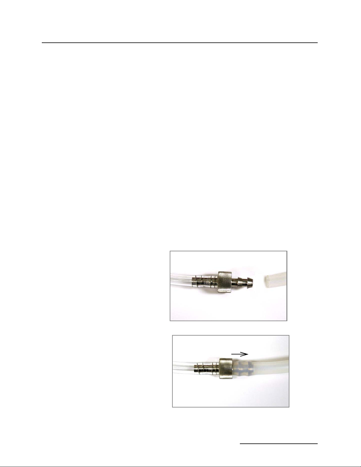
Attach vinyl suction line to the pump tubing with the tube coupling. Two couplings are available, one for each size of vinyl line.
Attach the vinyl suction line to the pump tube with the tubing
coupler. First, screw the threaded end into the suction line until
the flat surface is flush against the suction line (Figure 2-1).
Then, push the other end of the coupler into the end of the pump
tube until the other flat surface is flush against the tubing.
1.
2.
Figure 2-1 Attaching the suction line to the pump tubing
2-3
3700 Portable Samplers
Section 2 Setup Procedures
Once the coupler is attached to the pump tube, removal is difficult, and may require cutting the tube.
2.4.2 Attaching PTFE
Suction Line
2.4.3 Routing of the Suction
Line
Attach the PTFE line to the pump tubing by inserting the line
into the pump tubing and securing it with a suitable clamp.
Route the line from sampler to sampling point so that it is continuously sloped downhill. This helps to drain the suction line when
the peristaltic pump reverses to purge the line, and minimizes
the possibility of cross contamination. When the sampler is used
in near freezing temperatures, drain the suction line thoroughly
to minimize the possibility of frozen liquid clogging the line.
2.5 Strainers The
with our standard weighted polypropylene strainer (Figure 2-2)
installed on one end of the suction line and a tubing coupling on
the other end.
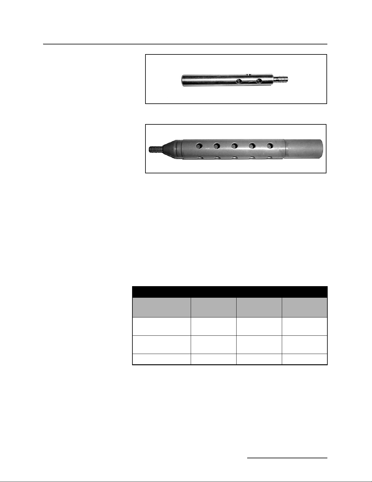
Additionally, Teledyne Isco offers two low flow stainless steel
strainers (Figure 2-3) for
For sampling from highly acidic flow streams, a weighted, CPVC
plastic-coated strainer is available (Figure 2-4).
The use of the strainer is optional. When heavy suspended solids
are involved and flow stream velocities are significant, some field
investigation results indicate that more representative samples
are obtained without the strainer.
You can purchase bulk suction line without strainers. Refer to
the Accessories List in the back of this manual. The strainer prevents solid particles larger than a specific diameter from
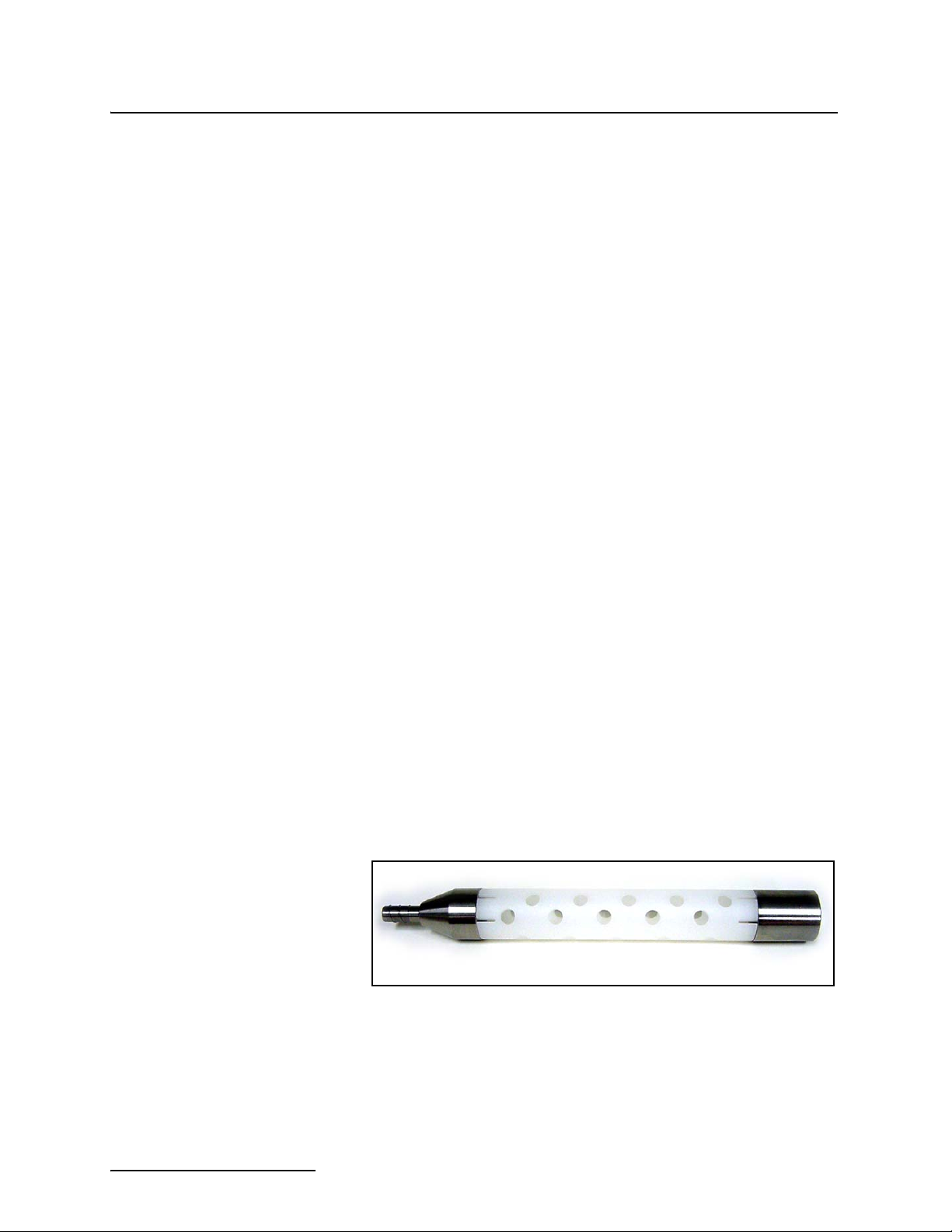
entering and clogging the suction line. Teledyne Isco recommends its use for bottom sampling or sampling from streams containing large solids. The
the
holes. The
PTFE
holes.
3
/8 inch ID vinyl suction lines are shipped from the factory
1
/4 inch ID and 3/8 inch ID suction lines.
1
1
/4-inch ID suction line have 15/64-inch (0.56 cm) diameter
3
/8-inch strainers supplied for use with the vinyl or
3
/8-inch ID suction line have 23/64-inch (0.9 cm) diameter
/4-inch strainers supplied for use with
Figure 2-2 Standard Weighted Polypropylene Strainer
2-4
3700 Portable Samplers
Section 2 Setup Procedures
Figure 2-3 Stainless Steel Strainer
Figure 2-4 CPVC Weighted Strainer
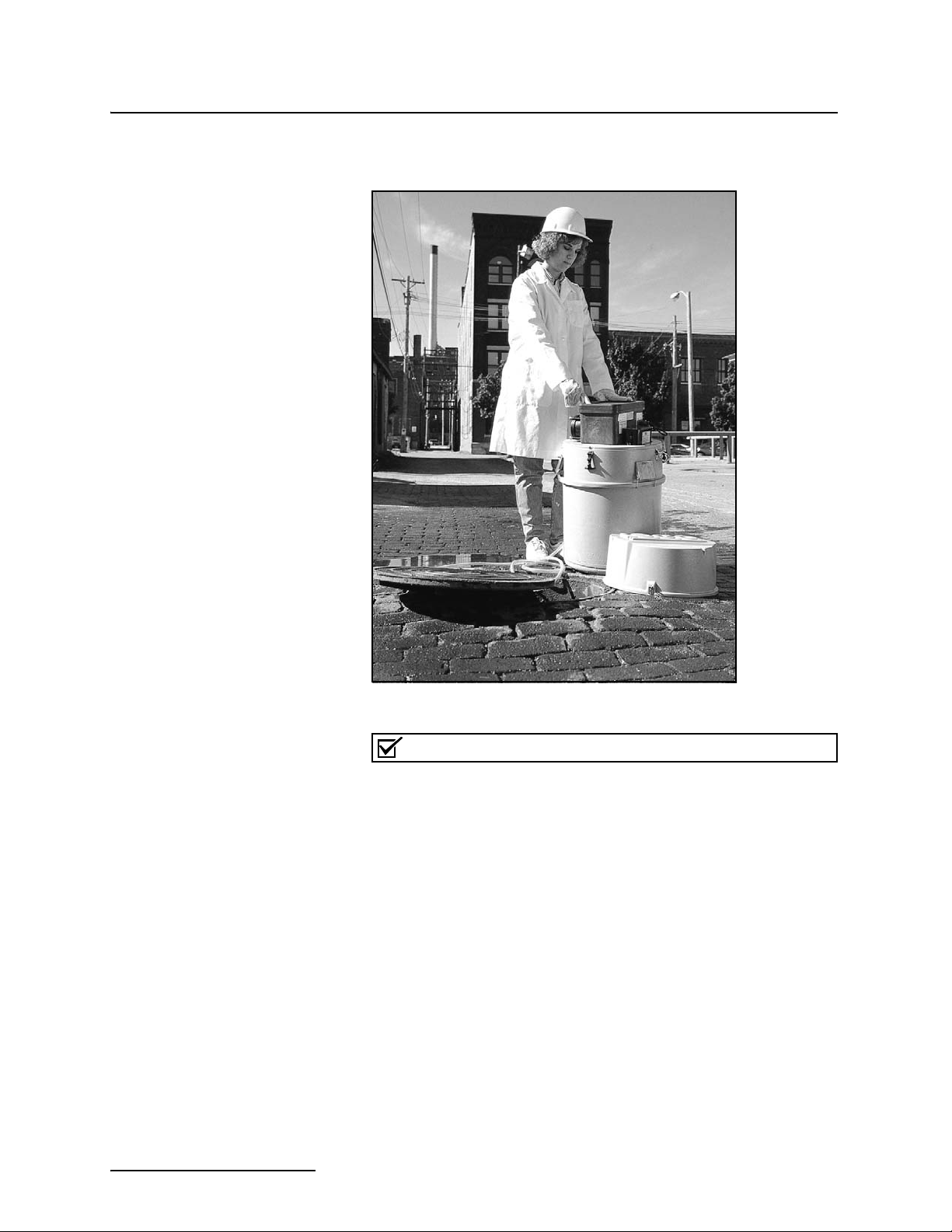
2.5.1 Intake Placement The proper placement of the sampler intake assures the collection of representative samples. Place the intake in the main flow, not in an eddy or at the edge of flow. The vertical position of the intake in the flow is important. An intake at the bottom may result in excess heavy solids and no floating materials, while placement at the top may result in the opposite.
The suction line tends to float in deep flow streams, dislodging
the line and strainer. The following chart shows the maximum
depths you can submerge the lines and strainers without risks of
flotation. At depths exceeding the safe depths, anchor the line
and strainer securely.
2.6 Connection to Power Source
Table 2-1 Strainers
Strainer
Standard Weighted
Vinyl
1
/4-inch (6 mm)
— 22 feet (6.7 m) 15 feet (4.5 m)
Polypropylene
Stainless Steel
14 feet (4.3 m) 22 feet (6.7 m) 15 feet (4.5 m)
Low Flow
CPVC
— 4 feet (1.2 m) 4 feet (1.2 m)
The 3700 Series must use one of four 12 VDC power sources: an
Isco AC Power Pack, an Isco Nickel-Cadmium Battery Pack, an
Isco sealed lead-acid battery, or an external 12V direct current
source (such as an automotive or marine battery). For complete
information on these power options and how to maintain them,
refer to the Power Products Guide that was shipped with your
sampler.
Vinyl
3
/8-inch (9 mm)
PTFE
3
/8-inch (9 mm)
2-5
3700 Portable Samplers
Section 2 Setup Procedures
2.7 Placement of the Sampler into Operation
Place your sampler on a relatively flat surface. Placing it on a
steep incline may cause the sample to miss the bottle opening.
Figure 2-5 Placement of the Sampler Adjacent to Manhole
Note
Although the suction line can extend to a liquid source as many
as 99 feet from the sampler, note that the maximum lift for the
peristaltic pump with either the PTFE or vinyl line is 26 feet.
When installing the sampler, be sure the head - the vertical distance between the level of the liquid source and the pump - is
no greater than 26 feet. The pump will not be able to deliver
samples for heads of 26 feet or greater.
If it is necessary to enter the manhole to position the strainer
and suction line, observe standard safety precautions. Refer to
Appendix C for a discussion of safety considerations.
The sampler will automatically cease operation after all bottles
have been filled or after the programmed number of samples
have been placed in the composite container (or composite sampling has been stopped by the float shut-off). When the sampling
routine has finished, the display will read “DONE.”
2-6
 Loading...