

Page 1
TT
race Oxygrace Oxyg
T
race Oxyg
TT
race Oxygrace Oxyg
en Analen Anal
en Anal
en Analen Anal
yzyz
yz
yzyz
erer
er
erer
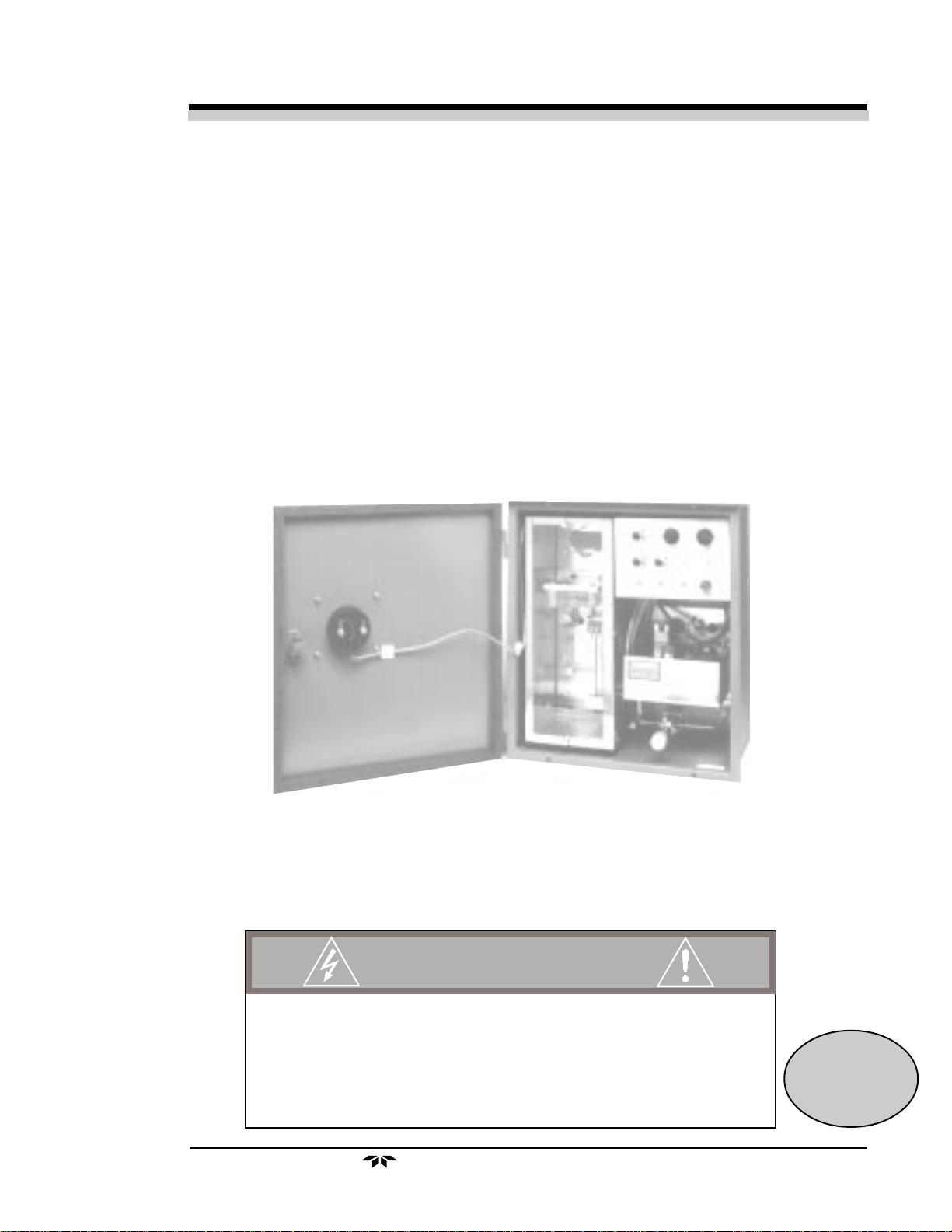
Model 356WA
Trace Oxygen Analyzer
Instruction Manual
DANGER
HIGHLY TOXIC AND OR FLAMMABLE LIQUIDS OR GASES MAY BE PRESENT IN THIS MONITORING SYSTEM.
PERSONAL PROTECTIVE EQUIPMENT MAY BE REQUIRED WHEN SERVICING THIS SYSTEM.
HAZARDOUS VOLTAGES EXIST ON CERTAIN COMPONENTS INTERNALLY WHICH MAY PERSIST FOR A
TIME EVEN AFTER THE POWER IS TURNED OFF AND DISCONNECTED.
ONLY AUTHORIZED PERSONNEL SHOULD CONDUCT MAINTENANCE AND/OR SERVICING. BEFORE
CONDUCTING ANY MAINTENANCE OR SERVICING CONSULT WITH AUTHORIZED SUPERVISOR/MANAGER.
Teledyne Analytical Instruments
P/N M356WA
09/14/99
ECO # 99-0373
i
Page 2

Model 356WModel 356W
Model 356W
Model 356WModel 356W
Copyright © 1999 Teledyne Analytical InstrumentsCopyright © 1999 Teledyne Analytical Instruments
Copyright © 1999 Teledyne Analytical Instruments
Copyright © 1999 Teledyne Analytical InstrumentsCopyright © 1999 Teledyne Analytical Instruments
All Rights Reserved. No part of this manual may be reproduced, transmitted,
transcribed, stored in a retrieval system, or translated into any other language or computer
language in whole or in part, in any form or by any means, whether it be electronic,
mechanical, magnetic, optical, manual, or otherwise, without the prior written consent of
Teledyne Analytical Instruments, 16830 Chestnut Street, City of Industry, CA 91749-
1580.
WarrantyWarranty
Warranty
WarrantyWarranty
This equipment is sold subject to the mutual agreement that it is warranted by us
free from defects of material and of construction, and that our liability shall be limited to
replacing or repairing at our factory (without charge, except for transportation), or at
customer plant at our option, any material or construction in which defects become
apparent within one year from the date of sale, except in cases where quotations or
acknowledgements provide for a shorter period. Components manufactured by others bear
the warranty of their manufacturer. This warranty does not cover defects caused by wear,
accident, misuse, or neglect. We assume no liability for direct or indirect damages of any
kind and the purchaser by the acceptance of the equipment will assume all liability for
any damage which may result from its use or misuse.
AA
A
AA
We reserve the right to employ any suitable material in the manufacture of our
apparatus, and to make any alterations in the dimensions, shape or weight of any parts, in
so far as such alterations do not adversely affect our warranty.
Important NoticeImportant Notice
Important Notice
Important NoticeImportant Notice
This instrument is intended to be used a tool to gather valuable data. The information provided by the instrument may assist the user in eliminating potential hazards
caused by the process that the instrument is intended to monitor; however,
that all personnel involved in the use of the instrument or its interface with the processthat all personnel involved in the use of the instrument or its interface with the process
that all personnel involved in the use of the instrument or its interface with the process
that all personnel involved in the use of the instrument or its interface with the processthat all personnel involved in the use of the instrument or its interface with the process
being measured be properly trained in the process itself, as well as all instrumentationbeing measured be properly trained in the process itself, as well as all instrumentation
being measured be properly trained in the process itself, as well as all instrumentation
being measured be properly trained in the process itself, as well as all instrumentationbeing measured be properly trained in the process itself, as well as all instrumentation
related to it.related to it.
related to it.
related to it.related to it.
The safety of personnel is ultimately the responsibility of those who control process
conditions. While this instrument may be able to provide early warning of imminent
danger, it has no control over process conditions, and can be misused. In particular, any
alarm or control system installed must be tested and understood, both as they operate and
as they can be defeated. Any safeguards required such as locks, labels, or redundancy
must be provided by the user or specifically requested of Teledyne.
The purchaser must be aware of the hazardous conditions inherent in the process(es)
he uses. He is responsible for training his personnel, for providing hazard warning
methods and instrumentation per the appropriate standards, and for ensuring that hazard
warning devices and instrumentation are maintained and operated properly.
it is essentialit is essential
it is essential
it is essentialit is essential
Teledyne Analytical Instruments, the manufacturer of this instrument, cannot accept
responsibility for conditions beyond its knowledge and control.
or implied by this document or any information disseminated by the manufacturer oror implied by this document or any information disseminated by the manufacturer or
or implied by this document or any information disseminated by the manufacturer or
or implied by this document or any information disseminated by the manufacturer oror implied by this document or any information disseminated by the manufacturer or
his agents is to be construed as a warranty of adequate safety control under the user'shis agents is to be construed as a warranty of adequate safety control under the user's
his agents is to be construed as a warranty of adequate safety control under the user's
his agents is to be construed as a warranty of adequate safety control under the user'shis agents is to be construed as a warranty of adequate safety control under the user's
process conditions.process conditions.
process conditions.
process conditions.process conditions.
ii
Teledyne Analytical Instruments
No statement expressedNo statement expressed
No statement expressed
No statement expressedNo statement expressed
Page 3

TT
race Oxygrace Oxyg
T
race Oxyg
TT
race Oxygrace Oxyg
en Analen Anal
en Anal
en Analen Anal
yzyz
yz
yzyz
erer
er
erer
T ab le of Contents
1 Introduction
1.1 Method of Operation................................................. 1-1
1.2 Required Equipment................................................. 1-2
1.2.1 Sample Conditioning................................... 1-2
1.2.2 Recorder /Meter Readout ........................... 1-2
2 Operational Theory
2.1 Sensor ..................................................................... 2-1
2.2 Humidifier ................................................................ 2-1
2.3 Flow System............................................................ 2-2
3 Installation
3.1 Location.................................................................... 3-1
3.2 Electrical Connections............................................. 3-1
3.3 Sample Connections ............................................... 3-2
4 Operations
4.1 Filling the Reservoir.................................................. 4-1
4.2 Detector Cell............................................................. 4-1
4.2.1 Cell Packaging ............................................ 4-1
4.2.2 Electrolyte ................................................... 4- 1
4.2.3 Cell Installation............................................ 4-3
4.3 Throttle Valve ........................................................... 4 -5
4.4 Humidity Control....................................................... 4-5
4.5 Power ....................................................................... 4 -7
4.6 Warm-Up and Stabilization....................................... 4-7
4.7 Calibration ................................................................ 4-7
5 Maintenance & Troubleshooting
5.1 Flowmeter and Humidifier ....................................... 5- 1
5.2 Cell Electrolyte Level............................................... 5-1
5.3 Reservoir ................................................................. 5-1
5.4 Calibration ............................................................... 5-1
5.5 Cell .......................................................................... 5-2
5.5.1 Electrolyte Replacement.............................. 5 -2
5.5.2 Lead Electrode............................................. 5 -2
5.6 Screen Assembly..................................................... 5-4
Teledyne Analytical Instruments
iii
Page 4

5.7 Reservoir and Humidifier Column ........................... 5 -4
5.8 Leak Detection ........................................................ 5-6
5.8.1 Leak Detection Procedure ........................... 5-6
5.8.2 Cell Leak...................................................... 5 -7
Appendix
Specifications ................................................................. A-1
Spare Parts List.............................................................. A-2
Drawing List.................................................................... A-3
Calibration Data.............................................................. A-4
Material Safety Data Sheets........................................... A-9
Model 356WModel 356W
Model 356W
Model 356WModel 356W
AA
A
AA
iv
Teledyne Analytical Instruments
Page 5

TT
race Oxygrace Oxyg
T
race Oxyg
TT
race Oxygrace Oxyg
en Analen Anal
en Anal
en Analen Anal
The Teledyne Analytical Instruments Model 356WA Trace Oxygen
Analyzer is designed to detect oxygen concentrations in process streams. It
utilizes Teledyne’s patented electrochemical sensor which requires minimal
maintenance and exhibits a 90% response in less than one minute. Cell
output is insensitive to flow rate changes within the operating range of the
analyzer’s flowmeter.
The Model 356WA features a welded stainless sampling system for
long-term, leak-free operation.
While the analyzer is offered in several configurations, they are virtually
identical with the exception of housing or options such as special meters. For
purposes of clarity, this manual will discuss the unit in general. The differences between the configurations are minor and will be obvious to the user.
yzyz
erer
yz
er
yzyz
erer
IntroductionIntroduction
Introduction
IntroductionIntroduction
Introduction 1Introduction 1
Introduction 1
Introduction 1Introduction 1
1.11.1
1.1
1.11.1
Gas from the process stream is fed through a sample line to the sample
inlet port of the analyzer. The sample is directed through the analyzer’s
sample system, where oxygen concentration is detected by the sensor. The
sensor generates an output signal which is read out on a suitable recorder or
meter.
The analyzer components include:
• A throttle valve and flowmeter to control sample flow
• A humidifier to condition the sample
• The measuring cell where catalytic conversion occurs
• An electronic amplifier circuit for converting the output of the
cell to a DC signal.
• A thermostatic assembly for temperature control in the cell
compartment
• A reservoir for providing make-up water to the humidifier.
Method of OperationMethod of Operation
Method of Operation
Method of OperationMethod of Operation
Teledyne Analytical Instruments
1-1
Page 6

1 Introduction1 Introduction
1 Introduction
1 Introduction1 Introduction
Model 356WModel 356W
Model 356W
Model 356WModel 356W
AA
A
AA
1.21.2
1.2
1.21.2
For proper operation, the analyzer may require accessory equipment,
particularly in the area of sample conditioning. The need for additional
equipment is dictated by the conditions of each application.
1.2.11.2.1
1.2.1
1.2.11.2.1
The sample must be free of entrained solids and condensable vapors,
and be at a relatively constant pressure between
more efficient operation is obtained with pressures in the range of
psigpsig
psig. Pressure surges can carry fluid from the humidifier into the cell and
psigpsig
impair cell operation. Filters, scrubbers, or pressure regulators are often
necessary, depending on local conditions.
1.1.
Filters.Filters.
1.
Filters. If filters are necessary, they should be conveniently
1.1.
Filters.Filters.
located near the analyzer, and installed in a fashion which permits
easy removal for periodic cleaning or replacement.
2.2.
Scrubbers.Scrubbers.
2.
Scrubbers. If the sample contains small quantities of acidic
2.2.
Scrubbers.Scrubbers.
anhydrides (SO2, etc.) or mercaptans (H2S, etc.) they will react
with the electrolyte or the cathode, and must be removed. A
caustic scrubber is usually effective.
Required EquipmentRequired Equipment
Required Equipment
Required EquipmentRequired Equipment
Sample ConditioningSample Conditioning
Sample Conditioning
Sample ConditioningSample Conditioning
1 and 100 psig1 and 100 psig
1 and 100 psig. However,
1 and 100 psig1 and 100 psig
5 to 105 to 10
5 to 10
5 to 105 to 10
3.3.
Pressure regulators.Pressure regulators.
3.
Pressure regulators. While the analyzer will accept pressures to
3.3.
Pressure regulators.Pressure regulators.
100 psig, a range of
pressure surges can affect instrument operation. In either case, the
use of a pressure regulator is advisable. Install the regulator as
close to the sample point as possible to reduce sample travel time
to a minimium. The regulator should incorporate a metallic
diaphragm to prevent the diffusion of atmospheric oxygen into
the sample.
1.2.21.2.2
1.2.2
1.2.21.2.2
The meter installed on the 356WA is either analog or digital. The
recorder used for analyzer signal readout is usually of the self-balancing
potentiometric type. It should have an input inpedance of
Output is 0 to 1VDC or less (optional: 1 to 5, 4 to 20, or 10 to 50 mADC).
Recorder /Meter ReadoutRecorder /Meter Readout
Recorder /Meter Readout
Recorder /Meter ReadoutRecorder /Meter Readout
5 to 10 psig5 to 10 psig
5 to 10 psig is recommended. In addition,
5 to 10 psig5 to 10 psig
10 10
ΩΩ
10
Ω or higher.
10 10
ΩΩ
1-2
Teledyne Analytical Instruments
Page 7

TT
race Oxygrace Oxyg
T
race Oxyg
TT
race Oxygrace Oxyg
en Analen Anal
en Anal
en Analen Anal
The sensor is an open-cathode cell, an electrochemical transducer
specific to oxygen. The cathode of the cell is composed of silver screen
elements with a large surface area. The screen assembly is mounted in an
acrylic block, with the lower edges of the screens immersed in potassium
hydroxide electrolyte. A thin layer of electrolyte is maintained on the surfaces of the screens by capillary action. A lead disk is positioned under the
screens and serves as the anode. An exploded view of the cell is showm in
Figure 5-1.
yzyz
erer
yz
er
yzyz
erer
Operational TheoryOperational Theory
Operational Theory
Operational TheoryOperational Theory
2.1 Sensor2.1 Sensor
2.1 Sensor
2.1 Sensor2.1 Sensor
Operational Theory 2Operational Theory 2
Operational Theory 2
Operational Theory 2Operational Theory 2
The sample gas stream is passed directly over the cathode screens,
initiating an electrochemical reaction. Four electrons are generated by the
oxidation of the lead anode, and are then used to reduce oxygen at the
cathode. The flow of electrons between the anode and cathode creates an
electric current which is directly proportional to the oxygen concentration in
the sample stream. In the absence of oxygen, no oxidation or reduction
takes place, and no current is produced.
In simplified form, the reaction may be described as follows: oxygen is
reduced at the cathode by the mechanism
4e- +O2 + 2H2O → 4OH
This cathodic half-reaction occurs simultaneously with the anodic halfreaction
Pb + 2OH- → PbO + H2O + 2e
The overall reaction is
O2+ 2Pb → 2PbO
2.2 Humidifier2.2 Humidifier
2.2 Humidifier
2.2 Humidifier2.2 Humidifier
-
-
It is necessary to maintain a film of electrolyte on the screens of the
electrode assembly. This means that the humidity of the sample as it flows
through the cell must be such that the water vapor pressure of the electro-
Teledyne Analytical Instruments
2-1
Page 8

2 Operational Theory2 Operational Theory
2 Operational Theory
2 Operational Theory2 Operational Theory
lyte is equal to the water vapor pressure in the sample gas. If the humidity
of the sample is too low, water will evaporate from the electrolyte, drying
the cell. If the sample humidity is too high, water will condense out into the
electrolyte, flooding the cell.
The sample is humidified by bubbling it through water in the humidifier
column just before it enters the cell. The humidifier column is in the same
heated compartment as the cell and so is held at the same temperature. The
water in the column, however, is cooled by evaporation into the sample gas.
Thus, the sample gas will normally have a humidity that is too low for
equilibrium with the cell. It is assumed here, of course, that since the cell
component is heated above ambient temperature, the sample gas is less than
saturated at the compartment temperature when it enters the analyzer.
The humidity of the sample is increased to be in equilibrium with the
cell electrolyte by heating the water in the humidifier column. The humidifer
heater is in the base of the column, and the amount of heating is adjusted
with the humidity control that is located on the panel of the control unit.
Model 356WModel 356W
Model 356W
Model 356WModel 356W
AA
A
AA
The amount of heating required depends on the sample flow rate, the
sample humidity, and the specific heat of the sample. The correct adjustment for the operating conditions of any particular installation is obtained by
checking the cell electrolyte level periodically and replenished when necessary according to the instructions in Section 4.2.3:
The humidifier column also contains baffles to stop water from splashing up into the line to the sample cell at high flow rates.
2.3 Flow System2.3 Flow System
2.3 Flow System
2.3 Flow System2.3 Flow System
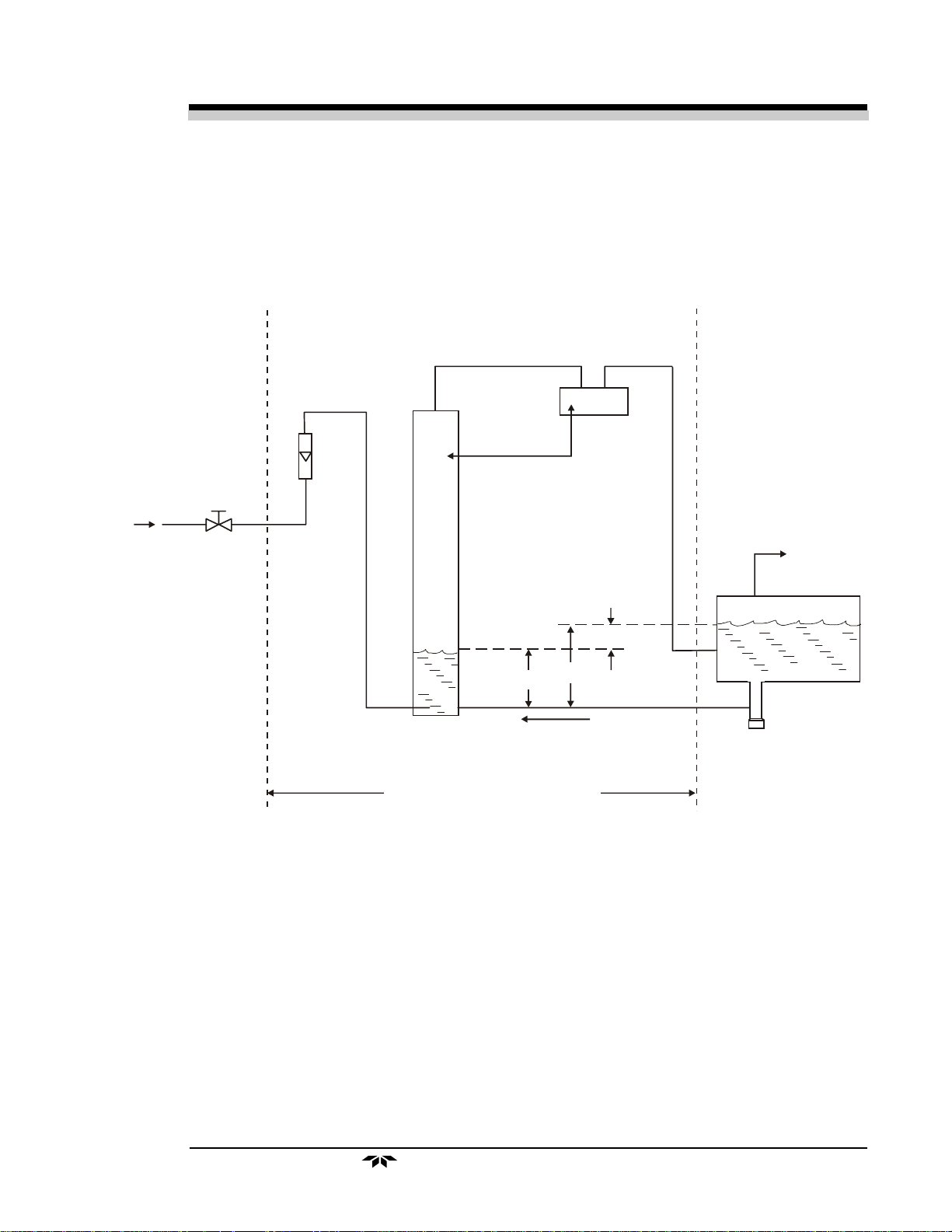
The analyzer flow system is shown schematically in Figure 2-1. It
includes a needle valve for adjusting the sample flow rate, a flowmeter to
indicate the sample flow required for calibration, the humidifier, the measuring cell, and an automatic level control system for the water in the humidifier.
As can be seen from Figure 2-1, the sample enters the humidifier
column against the pressure of a water column from the base of the humidifier to the water level in the reservoir, which is approximately 4 inches.
This determines the minimum sample pressure at which any sample can flow
through the analyzer. In practice, the sample pressure must be somewhat
greater than this in order to have an adequate flow rate.
Cell Installation
.
The automatic level control in the humidifier column is accomplished
by connecting the sample outflow from the cell to the bottom of the reser-
2-2
Teledyne Analytical Instruments
Page 9
TT
race Oxygrace Oxyg
T
race Oxyg
TT
race Oxygrace Oxyg
en Analen Anal
en Anal
en Analen Anal
yzyz
yz
yzyz
erer
er
erer
Cell
Operational Theory 2Operational Theory 2
Operational Theory 2
Operational Theory 2Operational Theory 2
Flowmeter
Sample In
Throttle
Valve
Humidifier
Column
Cell Comp a rtment
Pressure
ATM + (b - a)
Vent
b - a
b
a
Water
Reservoir
Drain
Figure 2-1: Flow System Schematic
Teledyne Analytical Instruments
2-3
Page 10

2 Operational Theory2 Operational Theory
2 Operational Theory
2 Operational Theory2 Operational Theory
voir. This places a back pressure on the sample in the cell and upper portion
of the humidifier column equal to the water column from the bottom of the
reservoir to the water level in the reservoir. Thus, the water level in the
humidifier column is held even with the sample connection at the bottom of
the reservoir. There will be a slight additional pressure in the top of the
humidifier column depending on the flow rate (the pressure needed to push
the sample through the cell and associated tubing), but at normal flow rates
this merely slightly lowers the level in the humidifier column.
The sample bubbles through the water in the reservoir on its way to the
outlet port. Some of the water vapor will re-condense, so that the sample
flows out of the outlet port saturated at the reservoir temperature, which is
slightly above ambient. The sample bubbling through the make-up water
will scrub out any oxygen which may be dissolved in it. This assures that the
sample will not pick up any oxygen as it passes through the humidifier
column.
Model 356WModel 356W
Model 356W
Model 356WModel 356W
AA
A
AA
2-4
Teledyne Analytical Instruments
Page 11

TT
race Oxygrace Oxyg
T
race Oxyg
TT
race Oxygrace Oxyg
en Analen Anal
en Anal
en Analen Anal
yzyz
erer
yz
er
yzyz
erer
InstallationInstallation
Installation
InstallationInstallation
3.1 Location3.1 Location
3.1 Location
3.1 Location3.1 Location
Installation 3Installation 3
Installation 3
Installation 3Installation 3
With proper shielding of the leads, the analyzer and the readout device
can be separated by as much as 1,000 feet. However, they should be placed
as close together as possible. For the most convenient operation, the readout recorder or meter should be within view of the controls, particularly
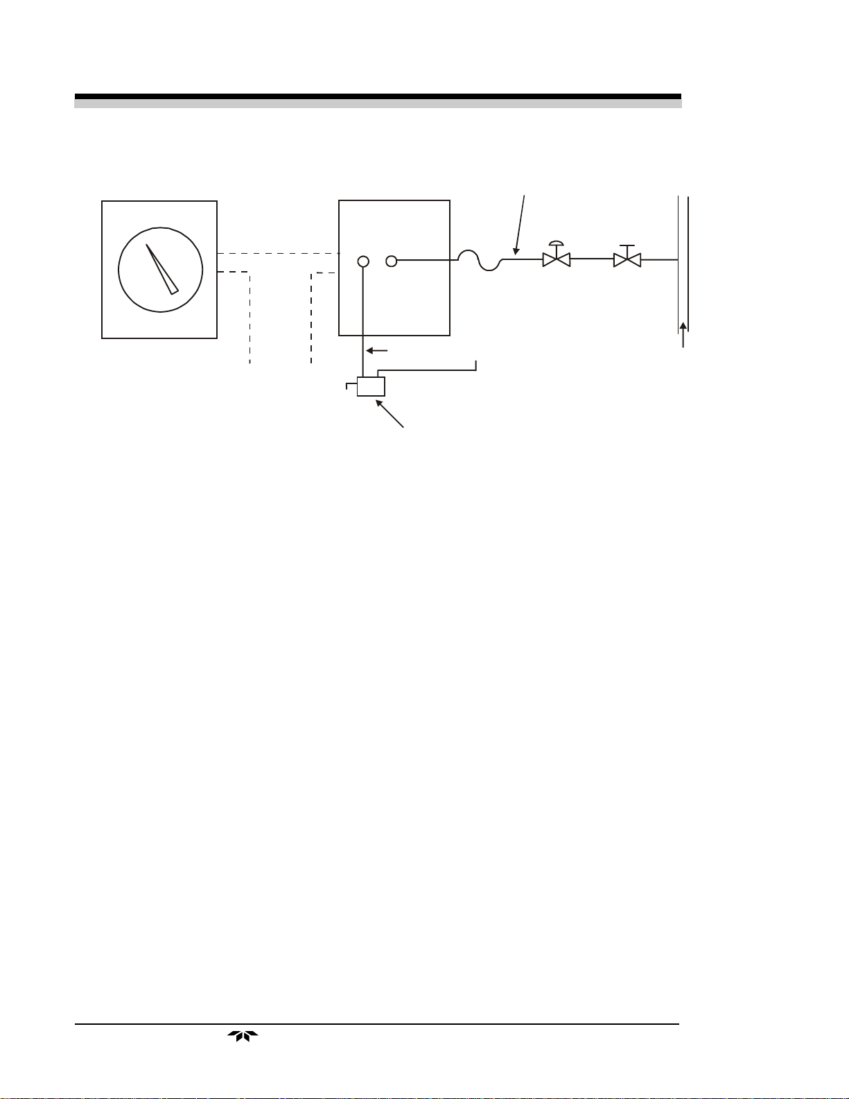
when the unit is being calibrated. Figure 2-1 depicts a typical system layout.
Other location considerations:
1) The analyzer should be sheltered from the elements.
2) Ambient temperature must be within
30 to 120 °F.30 to 120 °F.
30 to 120 °F.
30 to 120 °F.30 to 120 °F.
3) The unit should not be subject to excessive shock or vibration.
4) It should be as close as possible to the sample point.
5) There must be access to the back and side of the unit for
connection or maintenance of sample lines and power.
NOTE:NOTE:
NOTE:
NOTE:NOTE:
Since the level of the electrolyte in the measuring cell is critical andSince the level of the electrolyte in the measuring cell is critical and
Since the level of the electrolyte in the measuring cell is critical and
Since the level of the electrolyte in the measuring cell is critical andSince the level of the electrolyte in the measuring cell is critical and
the water level control system for the humidifier is gravity sensitive,the water level control system for the humidifier is gravity sensitive,
the water level control system for the humidifier is gravity sensitive,
the water level control system for the humidifier is gravity sensitive,the water level control system for the humidifier is gravity sensitive,
THE ANALYZER MUST BE MOUNTED SO THAT THE BOTTOM OFTHE ANALYZER MUST BE MOUNTED SO THAT THE BOTTOM OF
THE ANALYZER MUST BE MOUNTED SO THAT THE BOTTOM OF
THE ANALYZER MUST BE MOUNTED SO THAT THE BOTTOM OFTHE ANALYZER MUST BE MOUNTED SO THAT THE BOTTOM OF
THE CASE IS LEVEL.THE CASE IS LEVEL.
THE CASE IS LEVEL.
THE CASE IS LEVEL.THE CASE IS LEVEL.
3.2 Electrical Connections3.2 Electrical Connections
3.2 Electrical Connections
3.2 Electrical Connections3.2 Electrical Connections
A diagram of the necessary electrical connections is shown in Figure 2-2.
Note: Note:
Note:
Note: Note:
See the Interconnection Diagram (drawing A-37526) included in theSee the Interconnection Diagram (drawing A-37526) included in the
See the Interconnection Diagram (drawing A-37526) included in the
See the Interconnection Diagram (drawing A-37526) included in theSee the Interconnection Diagram (drawing A-37526) included in the
back of this manual, as well as any Addenda that may be includedback of this manual, as well as any Addenda that may be included
back of this manual, as well as any Addenda that may be included
back of this manual, as well as any Addenda that may be includedback of this manual, as well as any Addenda that may be included
with this manual for information specific to your instrument.with this manual for information specific to your instrument.
with this manual for information specific to your instrument.
with this manual for information specific to your instrument.with this manual for information specific to your instrument.
Teledyne Analytical Instruments
3-1
Page 12
3 Installation3 Installation
3 Installation
3 Installation3 Installation
Model 356WModel 356W
Model 356W
Model 356WModel 356W
AA
A
AA
Recorder
115 VAC Power and Ground
2 Power Leads
1 Ground Wire
(16 ga. Insulated)
Signal Leads
(22 ga. Twisted
Pair Shielded
Cable)
Figure 2-1 Typical System Layout
Perc ent Oxygen
Analyzer
Vent
Sample
In
1/4"
Tubing
Condensat e Trap
Vent
Sample Line
(1/4" or 1/8" Metal Tubing)
Pressure
Regulator
(5-10 psig Output)
The connections include a terminal for grounding the analyzer case and
chassis in accordance with accepted industrial practices. The maximum
power requirement is less than
1½ amperes at 115 VAC1½ amperes at 115 VAC
1½ amperes at 115 VAC.
1½ amperes at 115 VAC1½ amperes at 115 VAC
Shut Off
Valve
Sample
Line
3.3 Sample Connections3.3 Sample Connections
3.3 Sample Connections
3.3 Sample Connections3.3 Sample Connections
The sample line is connected at the back of the analyzer case as depicted in Figure 2-3. Use care in assembling any part of the sampling system
to avoid leaks. Oxygen can diffuse into the system through small leaks even
when sample pressure is much greater than atmospheric pressure. A 1/8"
female NPT fitting is installed on the back of the instrument for making
sample and vent line connections. Thepurge line is fitted with a 1/4" tube
fitting.
ConnectorsConnectors
1.
Connectors. Use straight tube connectors where possible.
ConnectorsConnectors
This facilitates removal of the analyzer section from the case
during maintenance or service.
LinesLines
2.
Lines. Lines should consist of metallic tubing, since oxygen can
LinesLines
diffuse through plastic. Use continuous tubing where possible.
VentVent
3.
Vent. The analyzed sample is vented through the back of the
VentVent
unit as shown in Figure 2-3.
3-2
Teledyne Analytical Instruments
Page 13
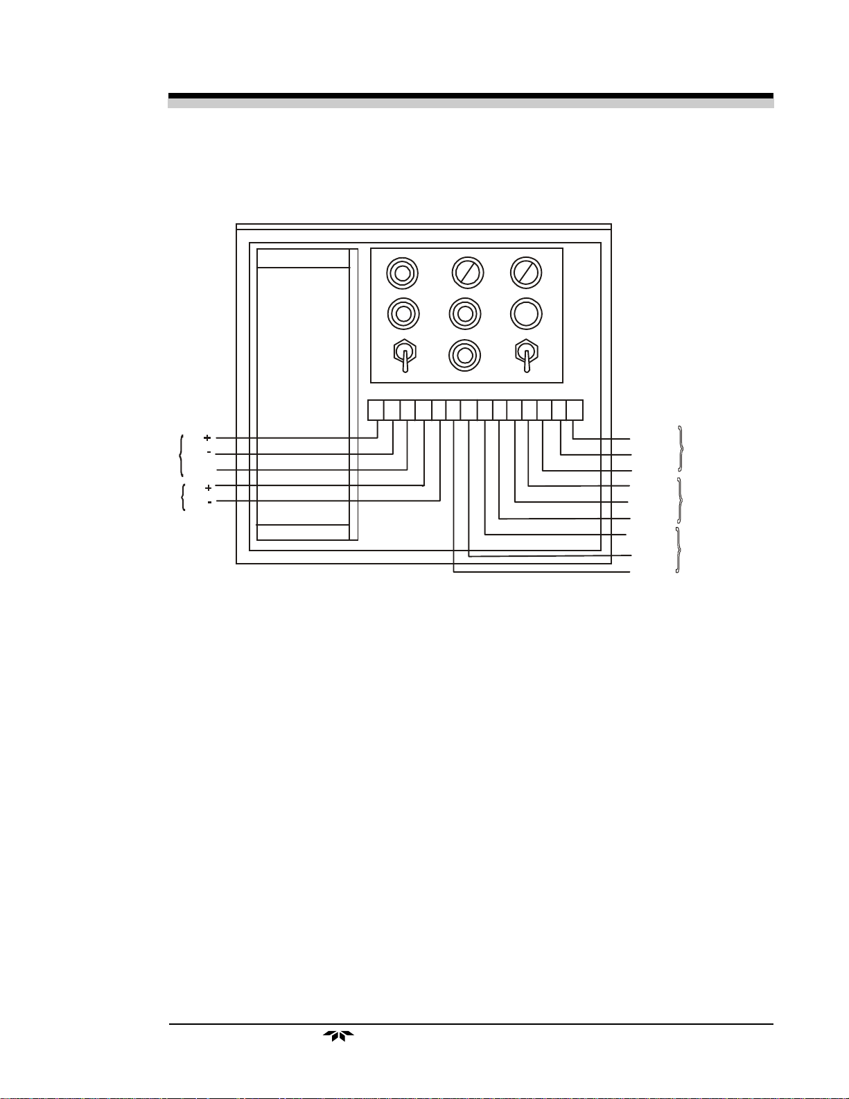
mV
Output
GND
Current
Output
TT
race Oxygrace Oxyg
T
race Oxyg
TT
race Oxygrace Oxyg
en Analen Anal
en Anal
en Analen Anal
yzyz
erer
yz
er
yzyz
erer
TS 1
1 2 3 4 5 6 7 8 9 10 11 12 13 14
Installation 3Installation 3
Installation 3
Installation 3Installation 3
HOT
NEUT
GND
NO
C
NC
NO
C
NC
AC Power In
150 Watt Max
Load
Alarm 2
Alarm 1
Figure 2-2: General Connection Diagram
See the specific Interconnection Diagram for your instrument in the drawing
package located at the back of the manual. See also any Addenda that may be
included with this manual.
The analyzer should have a vent line of ¼" diameter tubing at least two
feet long, running
downwarddownward
downward from the vent connection. This is to prevent
downwarddownward
air from diffusing into the reservoir and dissolving into the humidifier makeup water.
If it is not desirable to vent the sample into the atmosphere, a vent line
to carry the sample to a suitable venting area will be required. The sample
leaves the vent connection of the analyzer saturated with water vapor at a
temperature somewhat above ambient, so a suitable trap to remove condensate without plugging the vent line will be required. The vent line should
also be arranged so that it cannot become plugged by dirt or dust.
Teledyne Analytical Instruments
3-3
Page 14

3 Installation3 Installation
3 Installation
3 Installation3 Installation
15"
Model 356WModel 356W
Model 356W
Model 356WModel 356W
9"
AA
A
AA
18-1/4"
7/8" dia. holes
for 1/2" conduit
5/16"
17-9/16"
115 V 50/60 Hz
Pow er I n
Signal Out
2"
17"
7-15/16"
Sample
Purge
Vent
1/4" Female NPT
3-4
FIGURE 5 ANALYZER OUTLINE DIA GRAM
Figure 5: Gas Connections to Back of Analyzer
Teledyne Analytical Instruments
Page 15

TT
race Oxygrace Oxyg
T
race Oxyg
TT
race Oxygrace Oxyg
en Analen Anal
en Anal
en Analen Anal
yzyz
erer
yz
er
yzyz
erer
OperationsOperations
Operations
OperationsOperations
Operations 4Operations 4
Operations 4
Operations 4Operations 4
4.14.1
4.1
4.14.1
The reservoir is located on the right side of the analyzer case.
1) Insure that the cap on the drain spout is securely tightened.
2) Remove cap from fill port on top of reservoir.
3) Pour distilled water into reservoir until it is half full (about one
quart). The water will automatically flow into the humidifier
column.
4) Replace cap on fill port and securely tighten. A missing or loose
cap will permit the sample to vent into the analyzer case.
4.24.2
4.2
4.24.2
The cell is located in the heated compartment on the left side of the
analyzer case, as shown in Figure 4-1. To open the compartment, unscrew
the captive knurled knobs at the top and bottom of the compartment and
remove the plastic window.
4.2.14.2.1
4.2.1
4.2.14.2.1
The cell is packaged separately from the analyzer. It is filled with
distilled water to prevent oxidation of the electrodes from exposure to the
atmosphere. The cell should be left filled with the distilled water until the
analyzer is installed and ready for operation. The cell should not be exposed
to the atmosphere for any prolonged duration.
Filling the ReservoirFilling the Reservoir
Filling the Reservoir
Filling the ReservoirFilling the Reservoir
Detector CellDetector Cell
Detector Cell
Detector CellDetector Cell
Cell PackagingCell Packaging
Cell Packaging
Cell PackagingCell Packaging
4.2.24.2.2
4.2.2
4.2.24.2.2
The cell electrolyte is Teledyne Type A, used in applications where
there is a complete absence of acidic anhydrides (CO2, SO2) in the sample
gas. Type A electrolyte is a 10% solution (w/v) of reagent-grade potassium
hydroxide (KOH) in distilled water.
ElectrolyteElectrolyte
Electrolyte
ElectrolyteElectrolyte
Teledyne Analytical Instruments
4-1
Page 16

4 Operations4 Operations
4 Operations
4 Operations4 Operations
Cell Compartment Terminal Strip
Heater
Control Assembly
Model 356WModel 356W
Model 356W
Model 356WModel 356W
AA
A
AA
Cell
Assembly
Heate r
Flowmeter
Humidifier
Column
Assembly
Sample
System
Assembly
1 2 3 4 5
Span
Current Adj
2
1
Range
Alarm 1
Alarm 2
3
20
10
Humidifier
Control
2 Amp
30
Interconnect
Terminal Strip
Throttle
Valve
Sample
System
Assembly
with
Reservoir
Figure 4-1: Typical Model 306WA With 2 Alarm Option
WARNING:
Type A electrolyte is caustic. Use extreme care in
handling. Protective equipment including but not
limited to gloves and safety glasses should be worn
while handling electrolyte. Refer to the Material Safety
Data Sheet in the Appendix regarding potential hazards
and corrective action in case of accident.
Type B electrolyte is a 20 % solution (w/v) of potassium carbonate and
should be used when the CO2 level in the background gas is between 500
ppm and 1 %. This narrow range is rarely encountered. It is, however
available from the factory. Safety related information for this electrolyte can
be found in the Appendix.
Type C electrolyte is a 20 % solution (w/v) of potassium bicarbonate
and should be used when the CO2 level in the background gas is between 1
and 100 %. Safety related information for this electrolyte can be found in
the Appendix.
4-2
Teledyne Analytical Instruments
Page 17

TT
race Oxygrace Oxyg
T
race Oxyg
TT
race Oxygrace Oxyg
en Analen Anal
en Anal
en Analen Anal
Sufficient electrolyte is provided for initial servicing of the cell. Electrolyte for future service should be ordered from Teledyne. When ordering,
specify type and quantity.
yzyz
yz
yzyz
erer
er
erer
Operations 4Operations 4
Operations 4
Operations 4Operations 4
4.2.34.2.3
4.2.3
4.2.34.2.3
Prior to servicing and installing the cell, inspect the lead electrode in
the acrylic base for signs of oxidation, indicated by a reddish-brown or
yellow discoloration. If discoloration is noted, clean the cell as directed in
section 5.5.2 before placing it in service.
WARNING: Type A electrolyte is caustic. Use extreme care in
handling. Protective equipment including but not
limited to gloves and safety glasses should be worn
while handling electrolyte. Refer to the Material Safety
Data Sheet in the Appendix regarding potential hazards
and corrective action in case of accident.
1) Remove the four cell mounting bolts which secure the plastic
cover. Pour out the distilled water.
2) Pour about half the furnished electrolyte into the cell and slosh
until all components within the cell are wetted by the solution.
Drain and dispose of the solution.
3) Wipe the top of the cell and the O-ring with a clean, disposable
tissue to remove solution from the exterior.
interior of the cell.
4) Carefully pour in electrolyte until it just touches the bottom edge
of the silver screen assembly at all points. This is indicated by a
definite wicking of electrolyte onto the screen assembly at every
point along ithe bottom edge. It is essential at this point that the
bottom edge of the screen assembly be wetted at all points (as
seen by the wicking action), but not over-immersed (as large a
surface area as possible of the screen assembly must remain
above the electrolyte, while every point of the bottom edge must
be wetted). The level is correct when the bottom edge of the
sensor screen is wetted but not immersed; approximately 3/32 "of
the silver electrode extends into the pool of eelectrolyte.
Cell InstallationCell Installation
Cell Installation
Cell InstallationCell Installation
DO NOTDO NOT
DO NOT touch the
DO NOTDO NOT
NOTE:The electrolyte level in the cell is critically related to its sensitivity
due to the change in the cathode surface area exposed to the
eledctrolyte.
5) Carefully place the cell under the cell mounting plate with the
outer terminal toward the front. Secure in place with four bolts
supplied with the cell. Refer to Figure 4-2.
Teledyne Analytical Instruments
4-3
Page 18

4 Operations4 Operations
4 Operations
4 Operations4 Operations
O-Ring
Cell Mounting
Bolts
Flowmeter
Model 356WModel 356W
Model 356W
Model 356WModel 356W
Terminal Strip
No. 4
AA
A
AA
4-4
Cell Block
Sample Flow
Control Valve
Humidifier Column Heater
Humidifier Column
Figure 4-2: Cell Compartment Components
Teledyne Analytical Instruments
Page 19

TT
race Oxygrace Oxyg
T
race Oxyg
TT
race Oxygrace Oxyg
en Analen Anal
en Anal
en Analen Anal
6) Connect the red lead to the center terminal and the black lead to
NOTE:The silver screens in the cell have been specially treated to pro-
vide proper detection characteristics. They must be kept clean and
MUST NOT be touched. Even clean fingers secrete natural oils
which contaminate the screens. If the screens need straightening,
wash a small pair of tweezers thoroughly to remove any grease,
rinse them in distilled water, and use them to carefully bend the
screens back into place.
yzyz
erer
yz
er
yzyz
erer
the outer terminal.
Operations 4Operations 4
Operations 4
Operations 4Operations 4
4.34.3
4.3
4.34.3
The throttle valve is located at the top of the reservoir tank. Refer to
Figure 4-1.
1) Gently turn the valve counterclockwise. A stream of bubbles
should appear at the base of the humidifier column, and the float
of the flowmeter should rise in its tube.
2) Adjust the valve so that the flowmeter float is centered in the
flow rate reference indicator.
CAUTION: Open the throttle valve carefully. Excessive flow rate
may cause water in the humidifier column to be carried
into the detector cell. This can cause erratic readings
and may require disassembly, cleaning, and refilling of
the sensor
3) The flowmeter indicator has been factory set to a flow rate of
150 cc/min150 cc/min
150 cc/min. for the specified sample gas.
150 cc/min150 cc/min
CAUTION: Excessive flow rate may cause water in the humidifier
to be carried to the flowmeter causing moisture to
accumulate. This can cause the ball to stick in the
flowmeter. To remove moisture, remove the flowmeter
and allow to air or blow dry. Refer to the detailed instructions in Figure 5-2 for removal and installation of
the column.
Throttle ValveThrottle Valve
Throttle Valve
Throttle ValveThrottle Valve
.
4.44.4
4.4
4.44.4
The humidity control is located on the front panel of the control unit,
and is adjusted to maintain a constant electrolyte level in the detector cell.
In effect, the control governs the humidity of the sample which is directed
to the cell.
Humidity ControlHumidity Control
Humidity Control
Humidity ControlHumidity Control
Teledyne Analytical Instruments
4-5
Page 20

4 Operations4 Operations
4 Operations
4 Operations4 Operations
Wick Saturated With KOH
Electrolyte Solution
Outside Electrode Connected to
"Y" Terminal Post (+)
Oxygen Generated Here
Model 356WModel 356W
Model 356W
Model 356WModel 356W
Electrical Terminal Board
Sub-Assembly
AA
A
AA
4-6
O-Ring
Inside Electrode Connected
to "B" Terminal Po st (-)
Hydrogen Generated Here
Figure 8: Calibrator Assembly
Teledyne Analytical Instruments
Page 21

TT
race Oxygrace Oxyg
T
race Oxyg
TT
race Oxygrace Oxyg
en Analen Anal
en Anal
en Analen Anal
yzyz
yz
yzyz
erer
er
erer
Operations 4Operations 4
Operations 4
Operations 4Operations 4
1) At start-up, the humidity control knob should be set to
the cell electrolyte level as a reference. Approximately 3/32" of
the bottom edge of the screen assembly should be immersed in
the electrolyte.
2) Operate the analyzer for 24 hours and compare the electrolyte
level with the “reference” established in Step 1. If the level is
lower than the reference, adjust the knob a few divisions
clockwise; if higher, adjust a few divisions counterclockwise.
3) Operate another 24 hours and repeat Step 2.
4) Continue adjustments at ever-increasing intervals until a constant
electrolyte level is attained in the cell.
Once the analyzer is suitably located, all components serviced and
installed, and sample and electrical connections made, the instrument is
ready for operation.
4.54.5
4.5
4.54.5
When power is turned on, power is applied to the cell compartment
heater. The cell operates without applied power, but its output will vary
with changes in ambient temperature.
PowerPower
Power
PowerPower
30 30
30. Note
30 30
4.64.6
4.6
4.64.6
When the analyzer is initially put into operation, the air in the lines and
sample passages will drive the output indication to the top of the scale. The
time required to sweep out this residual air may be several hours before an
on-scale indication is reached. During this time the cell compartment is
heating and reaching its controlled temperature.
4.74.7
4.7
4.74.7
The analyzer is calibrated by adding a known amount of oxygen into
the analyzer by means of a calibrated span gas. The sensitivity of the analyzer is adjusted until the change indicated by the analyzer is equal to the
amount of oxygen known to be present in the span gas. The span gas must
be composed of the same elements as the specified sample gas if the
analyzer's calibrated flowmeter is to be used. TBE/AI recommends that the
oxygen content of the span gas be between 70–90% of full scale on the
range of interest.
Warm-Up and StabilizationWarm-Up and Stabilization
Warm-Up and Stabilization
Warm-Up and StabilizationWarm-Up and Stabilization
CalibrationCalibration
Calibration
CalibrationCalibration
Teledyne Analytical Instruments
4-7
Page 22

4 Operations4 Operations
4 Operations
4 Operations4 Operations
To calibrate the analyzer:
1. Shut the sample gas off, disconnect the sample in line and
connect the the span gas to the sample inlet. Allow the span gas
to flow through the system. Adjust the span gas flow rate until
the flowmeter float is centered in the flowmeter reference
indicator. Note the reading of the external recorder or meter.
2. Turn the range selector switch to the range which encompases
the oxygen concentration of the span gas. The meter or recorder
should move upscale and indicate the exact concentration of
oxygen in the span gas.
3. If the external recorder/meter does not indicate the proper
amount of oxygen, adjust the span dial until it does.
4. After the recorder or meter has stabilized on the proper readout,
turn off the span gas flow, disconnect the span gas, reconnect
the sample gas and establish the proper flow.
Model 356WModel 356W
Model 356W
Model 356WModel 356W
AA
A
AA
4-8
Teledyne Analytical Instruments
Page 23

TT
race Oxygrace Oxyg
T
race Oxyg
TT
race Oxygrace Oxyg
en Analen Anal
en Anal
en Analen Anal
yzyz
yz
yzyz
erer
er
erer
Maintenance & Maintenance &
Maintenance &
Maintenance & Maintenance &
TT
T
TT
rr
ouboub
r
oub
rr
ouboub
leshooting 5leshooting 5
leshooting 5
leshooting 5leshooting 5
Maintenance & Maintenance &
Maintenance &
Maintenance & Maintenance &
After the analyzer has been put into operation and calibration has been
accomplished, routine inspection will be required for normal operation.
5.1 Flowmeter and Humidifier5.1 Flowmeter and Humidifier
5.1 Flowmeter and Humidifier
5.1 Flowmeter and Humidifier5.1 Flowmeter and Humidifier
The flowmeter and humidifier column must be checked daily to insure
proper flow, and corrected as necessary. Refer to Section 2.2:
and 4.4:
as necessary. Refer to Section 4.2.3:
the electrolyte is when the bottom edge of the sensor screen is wetted but not
immersed. Approximately 3/32 " of the silver electrode should extend into the
pool of electrolyte.
Throttle Valve
5.2 Cell Electrolyte Level5.2 Cell Electrolyte Level
5.2 Cell Electrolyte Level
5.2 Cell Electrolyte Level5.2 Cell Electrolyte Level
The level of electrolyte in the cell must be checked daily and adjusted
.
TT
rr
ouboub
T
r
TT
rr
Cell Installation
leshootingleshooting
oub
leshooting
ouboub
leshootingleshooting
Humidifier
. The proper level for
5.3 Reservoir5.3 Reservoir
5.3 Reservoir
5.3 Reservoir5.3 Reservoir
The water level in the reservoir should be checked at least every two
weeks. Follow this procedure:
a) Remove the cap from the filler spout.
b) Obtain a clean glass tube about 4 to 5 inches long and about ¼ "
outer diameter.
c) Lower the tube into the tank through the filler spout until it
touches bottom.
d) Place a finger over the end of the tube, and withdraw the tube
from the tank. The height of water in the tube is the height
of the water level in the tank.
e) If the water level in the reservoir is below
distilled water.
f) Replace the filler spout cap securely after verifying that the O-
ring seal is in good condition.
Teledyne Analytical Instruments
1 "1 "
1 ", add a quart of
1 "1 "
5-1
Page 24

5 Maintenance & 5 Maintenance &
5 Maintenance &
5 Maintenance & 5 Maintenance &
5.4 Calibration5.4 Calibration
5.4 Calibration
5.4 Calibration5.4 Calibration
The sensitivity of the unit should be checked at two to four week
intervals. Calibration procedures are described in Section 4.7:
5.5 Cell5.5 Cell
5.5 Cell
5.5 Cell5.5 Cell
The electrochemical reaction in the analytical process results in the
accumulation of lead ions in the electrolyte, making the replacement of the
lead electrode or the electrolyte necessary.
5.5.1 Electrolyte Replacement5.5.1 Electrolyte Replacement
5.5.1 Electrolyte Replacement
5.5.1 Electrolyte Replacement5.5.1 Electrolyte Replacement
Replace the electrolyte at least every two months, or even more frequently if foreign matter is accumulating in the cell. Remove the cell from is
compartment, and drain, clean, rinse, and refill as described in Section 4.2.3:
Cell Installation
as outlined in Section 4.7:
TT
rr
ouboub
T
TT
r
rr
leshootingleshooting
oub
leshooting
ouboub
leshootingleshooting
Calibration
. After the cell is serviced or replaced, calibrate the analyzer
Calibration
.
Model 356WModel 356W
Model 356W
Model 356WModel 356W
.
AA
A
AA
5.5.2 Lead Electrode5.5.2 Lead Electrode
5.5.2 Lead Electrode
5.5.2 Lead Electrode5.5.2 Lead Electrode
If electrode is discolored when new, or has obviously deteriorated from
use, it may be necessary to clean or replace the electrode. Use the following
procedure while referring to Figure 5-1.
If the lead electrode is simply discolored, clean the entire cell according
to the following procedure:
a) Heat a quart of Teledyne cleaning solution to slightly below the
boiling point, and completely fill the cell cavity with the heated
solution.
b) Let the solution stand for approximately five minutes. Drain and
dispose of solution in an approved manner.
c) Repeat steps a) and b).
d) Rinse the cell with distilled water and then fill with electrolyte.
Let stand for approximately two minutes and then drain and
dispose of electrolyte in an approved manner.
e) Refill the cell with electrolyte, immersing the lower edge of the
33
3
33
//
" "
silver screens to about a
If the lead electrode is obviously beyond repair, it must be replaced.
3232
/
32
" depth.
3232
//
" "
a) Remove the terminal nuts by removing them from the mounting
screws.
b) Carefully remove the screw which holds the screen assembly in
place. Remove the screen assembly. Use clean tweezers and
Teledyne Analytical Instruments5-2
dodo
do
dodo
Page 25

TT
race Oxygrace Oxyg
T
race Oxyg
TT
race Oxygrace Oxyg
Mounting Bolts (4)
en Analen Anal
en Anal
en Analen Anal
yzyz
yz
yzyz
erer
er
erer
Cell Block
Maintenance & Maintenance &
Maintenance &
Maintenance & Maintenance &
Cell Mounting
Nuts (4)
TT
T
TT
rr
ouboub
r
oub
rr
ouboub
leshooting 5leshooting 5
leshooting 5
leshooting 5leshooting 5
Terminal seal
O-rings (2)
Cover
Lead Electrode
Cathode Screen
Assembly
O-Ring
Figure 5-1: Cell Assembly
Teledyne Analytical Instruments
5-3
Page 26

5 Maintenance & 5 Maintenance &
5 Maintenance &
5 Maintenance & 5 Maintenance &
not touch it with your fingersnot touch it with your fingers
not touch it with your fingers. Avoid any possible
not touch it with your fingersnot touch it with your fingers
contamination of the screen.
c) Cleanse the cell thoroughly in electrolyte solution.
d) Insert the new lead electrode in place in the cell body and secure
with lock washers and screws.
e) Carefully install screen assembly and secure with mounting
screw.
f) Immerse the cell assembly in hot cleaning solution and then rinse
in distilled water.
TT
T
TT
rr
ouboub
r
oub
rr
ouboub
leshootingleshooting
leshooting
leshootingleshooting
Model 356WModel 356W
Model 356W
Model 356WModel 356W
AA
A
AA
g) Install prepared cell assembly as described in Section 4.2.3:
Installation
5.6 Screen Assembly5.6 Screen Assembly
5.6 Screen Assembly
5.6 Screen Assembly5.6 Screen Assembly
The screen assembly will become discolored after prolonged use due to
contamination. When this occurs, and if the cell no longer displays adequate
sensitivity, the entire cell assembly must be replaced. Refer to Section 4.2.3:
Cell Installation
Approximately once each year the reservoir and humidifier column
should be drained and cleaned. Use the following procedure:
a) Reduce sample flow to approximately
b) Refer to Figure 4-1. Place a small funnel with attached tubing
c) Replace the drain spout cap, turn the sample flow off, and
for cell installation instructions.
5.7 Reservoir and Humidifier Column5.7 Reservoir and Humidifier Column
5.7 Reservoir and Humidifier Column
5.7 Reservoir and Humidifier Column5.7 Reservoir and Humidifier Column
beneath the drain spout which is located on the underside of the
reservoir. Remove the drain spout cap and allow the reservoir
and humidifier column to drain thoroughly.
remove the fill cap on the top of the reservoir.
..
.
..
50 cc/min50 cc/min
50 cc/min.
50 cc/min50 cc/min
Cell
d) Add a small amount of electrolyte to a pint of warm distilled
water. Pour the solution into the reservoir and replace the fill cap.
e) Gently open the throttle valve and permit the sample to flow for
five to ten minutes.
f) Reduce the sample flow to
from the reservoir. When drained, replace the drain cap and turn
off the sample flow.
g) Rinse by filling with distilled water and draining several times.
h) If the humidifier column still retains deposits on its walls, it should
be removed and cleaned with a brush and suitable cleaner. See
Teledyne Analytical Instruments5-4
50 cc/min50 cc/min
50 cc/min. and drain the solution
50 cc/min50 cc/min
Page 27

TT
race Oxygrace Oxyg
T
race Oxyg
TT
race Oxygrace Oxyg
en Analen Anal
en Anal
en Analen Anal
NOTE: If electrolyte has severely etched the
column, it should be replaced.
i) After the reservoir and column
1) Grasp the tube, and with a
yzyz
erer
yz
er
yzyz
erer
Figure 5-2. After cleaning,
thoroughly rinse the column in
distilled water before
reinstalling.
have been cleaned, refill the
reservoir as outlined in Section
4.1:
Filling the Reservoir
Removing the HumidifierRemoving the Humidifier
Removing the Humidifier
Removing the HumidifierRemoving the Humidifier
Column:Column:
Column:
Column:Column:
twisting motion, work it up into
the top humidifier block until it
clears the bottom block
completely.
Maintenance & Maintenance &
Maintenance &
Maintenance & Maintenance &
.
TT
T
TT
rr
ouboub
r
oub
rr
ouboub
leshooting 5leshooting 5
leshooting 5
leshooting 5leshooting 5
2) Angle the bottom of the tube
towards you and twist it free of
the top block.
3) The top and bottom O-rings will
remain captive in their blocks.
To Reinstall:To Reinstall:
To Reinstall:
To Reinstall:To Reinstall:
1) Engage the top of the tube in the
top block at an angle and twist
up into the cavity of the top
block unit the bottom of the tube
clears the bottom block.
2) Swing the tube into line, and
twist down into the bottom
block until the tube seats.
NOTE:NOTE:
NOTE:
NOTE:NOTE:
Refer to the Spare Parts List in the Appendix for replacement part numbers for the
The flowmeter is similarly constructed
and can be removed and reinstalled
following the same procedure outlined
above.
Figure 5-2: Removing/Replacing the
Humidifier
Teledyne Analytical Instruments
5-5
Page 28

5 Maintenance & 5 Maintenance &
5 Maintenance &
5 Maintenance & 5 Maintenance &
flowmeter column or humidifier column.
5.9 Leak Detection5.9 Leak Detection
5.9 Leak Detection
5.9 Leak Detection5.9 Leak Detection
The most frequent cause of trouble in trace measurement is leakage.
Tiny leaks which may be unnoticeable can cause serious errors in trace
measurements. One of the principal problems is that air can diffuse into a gas
line through a small leak, even though the gas pressure in the line may
greatly exceed atmospheric pressure.
When a leak occurs in a system where the mass flow velocity is less
than the molecular velocity, gas molecules move in both directions through
the leak. The net flow of a particular gas, e.g. oxygen, will depend on the
relative partial pressure of that gas on each side of the leak. In a sample
having only a few parts-per-million oxygen, there will be a net flow of
oxygen inward unless the sample pressure is many thousands of pounds.
5.9.1 Leak Detection Procedure5.9.1 Leak Detection Procedure
5.9.1 Leak Detection Procedure
5.9.1 Leak Detection Procedure5.9.1 Leak Detection Procedure
The procedure outlined here is based on the premise that the leak rate is
independent of sample flow rate.
TT
T
TT
rr
ouboub
r
oub
rr
ouboub
leshootingleshooting
leshooting
leshootingleshooting
Model 356WModel 356W
Model 356W
Model 356WModel 356W
AA
A
AA
a) Stop the sample flow to permit oxygen to accumulate at the point
of the leak.
b) After approximately one minute, restart the sample flow. It is
advisable to practice establishing the flow rate to
reference flow indication on the flowmeter, with one quick turn
of the throttle valve.
c) Simultaneous to restarting the flow, start a stopwatch to measure
the time required for the recorder/meter to respond to the
accumulated oxygen.
d) The following are approximate times for the accumulated oxygen
to reach the cell from various points in the sample path through
the analyzer at
1.5 to 2 seconds Calibrator
3.5 to 3.75 seconds Base of humidifier column*
5.5 seconds Flowmeter
6.5 seconds Metering valve
7.5 seconds Gas connection at rear of analyzer
> than 7.5 seconds Sample connection lines leading to
* A leak at this location may indicate a leak in the column or in the
reservoir system.
150 cc/min150 cc/min
150 cc/min.
150 cc/min150 cc/min
analyzer
150 cc/min150 cc/min
150 cc/min., the
150 cc/min150 cc/min
5.9.2 Cell Leak5.9.2 Cell Leak
5.9.2 Cell Leak
5.9.2 Cell Leak5.9.2 Cell Leak
Teledyne Analytical Instruments5-6
Page 29

TT
race Oxygrace Oxyg
T
race Oxyg
TT
race Oxygrace Oxyg
en Analen Anal
en Anal
en Analen Anal
If there is no rise in oxygen reading when the sample flow is restarted in
step 5.9.1.b, the measuring cell should be checked for leaks. The two most
likely leaks locations are at the two terminal seal O-rings, or at the large Oring in the cell block mounting base.
Check that the terminals are screwed tightly into place. Frequently,
when a leak occurs at a terminal connection, a greenish crystalline deposit
will be found inside the cell around the terminal mounting screw. This is lead
carbonate, which is formed by carbon dioxide in the air reacting with lead
ions in the electrolyte.
If the large O-ring at the mounting plate is leaking, the oxygen indication will begin rising almost immediately after the sample flow is stopped. It
will continue to rise until sample flow is restarted, at which time it will begin
to gradually decrease.
yzyz
yz
yzyz
erer
er
erer
Maintenance & Maintenance &
Maintenance &
Maintenance & Maintenance &
TT
T
TT
rr
ouboub
r
oub
rr
ouboub
leshooting 5leshooting 5
leshooting 5
leshooting 5leshooting 5
Teledyne Analytical Instruments
5-7
Page 30

5 Maintenance & 5 Maintenance &
5 Maintenance &
5 Maintenance & 5 Maintenance &
TT
T
TT
rr
ouboub
r
oub
rr
ouboub
leshootingleshooting
leshooting
leshootingleshooting
Model 356WModel 356W
Model 356W
Model 356WModel 356W
AA
A
AA
SymptomSymptom
Symptom
SymptomSymptom
No analyzer response to
oxygen.
CauseCause
Cause
CauseCause
a) Poor electrical connection,
or F1 fuse (a standard 2
amp Slo-Blo fuse) has
blown.
b) Cell electrolyte level too
low.
c) Dirty cell.
d) Short between cell cathode
and anode (the screen to
lead [the base material] is
shorted.)
e) If d) above corrects the
problem, the cell has
probably been poisoned,
probably by fluid flowing into
the cell humidifier column.
f) Cell has been poisoned by a
component in the sample.
What What
What
What What
a) Verify proper connection
from the cell through the
control unit to the external
recorder or meter; check for
blown fuse. Replace as
necessary.
b) Inspect electrolyte level and
add as necessary. See
Section 4.2.3, item 4.
c) Remove cell and clean
thoroughly. See Section
4.2.3.
d) Correct short. Refill with
fresh electrolyte as needed.
e) Check for excessive flow-
rate.
Check for excessive foaming in the humidifier column.
Drain and clean reservoir as
necessary. Refer to Section
5.8.
f) If there has been no change
in the normal sample
composition, a scrubber
may be required to remove
the offending component.
TT
o Doo Do
T
o Do
TT
o Doo Do
Cell lacks sensitivity.
a) Cell electrolyte level too low
due to misadjusted or faulty
humidity control.
b) Cell electrolyte too high,
due to misadjusted or faulty
humidity control.
c) Faulty humidity control.
Teledyne Analytical Instruments5-8
a) Add electrolyte as neces-
sary. Adjust humidity
control. See Section 4.5.
b) Drain electrolyte and refill.
Adjust humidity control. See
Section 4.5.
c) • Shut off main power.
• Disconnect orange wire
from TS1 terminal 5,
place a voltmeter (set to
AC current, range 0–100
mA) in series with TS1-5
and the disconnected
orange wire.
CAUTION: High voltage AC
present.
Page 31

TT
race Oxygrace Oxyg
T
race Oxyg
TT
race Oxygrace Oxyg
en Analen Anal
en Anal
en Analen Anal
yzyz
yz
yzyz
erer
er
erer
Maintenance & Maintenance &
Maintenance &
Maintenance & Maintenance &
TT
T
TT
rr
ouboub
r
oub
rr
ouboub
leshooting 5leshooting 5
leshooting 5
leshooting 5leshooting 5
SymptomSymptom
Symptom
SymptomSymptom
Cell lacks sensitivity (continued.)
CauseCause
Cause
CauseCause
Faulty humidity control (contin-
ued.)
What What
What
What What
• Turn humidifier control
completely counterclockwise.
• Turn on main power.
• While watching the
voltmeter, turn the
humidifier control clockwise; the meter reading
should go from 0–50
milliamps. If not, replace
the humidifier heater
element or the humidifier
heater control. To determine which should be
replaced, see paragraph
below.
If there is no current, either
the humidifier element or
control is defective. To
determine which it is:
• Turn the humidifier control
knob fully ccw.
• Disconnect the voltmeter
from TS1-5 and orange
wire. Reconnect the
orange wire.
• Change the voltmeter
function to 200V AC.
• Place the voltmeter
across TS1-5 and terminal TS1-4.
• Watching the meter, turn
the humidifier control
knob cw and watch the
voltmeter read 0–110 to
120V AC.
• If not, replace R2 (behind
the control knob); see
paragraph below.
• If there is voltage, replace
the heater element; see
paragraph below.
TT
o Doo Do
T
o Do
TT
o Doo Do
Teledyne Analytical Instruments
5-9
Page 32

5 Maintenance & 5 Maintenance &
5 Maintenance &
5 Maintenance & 5 Maintenance &
TT
T
TT
rr
ouboub
r
oub
rr
ouboub
leshootingleshooting
leshooting
leshootingleshooting
Model 356WModel 356W
Model 356W
Model 356WModel 356W
AA
A
AA
SymptomSymptom
Symptom
SymptomSymptom
Cell lacks sensitivity (continued.)
CauseCause
Cause
CauseCause
Faulty humidity control (contin-
ued.)
What What
What
What What
To replace humidifierTo replace humidifier
To replace humidifier
To replace humidifierTo replace humidifier
controlcontrol
control:
controlcontrol
• Shut off all power and
remove the AC power
cord from the power
source.
• Refer to wiring diagram D18633 (upper right-hand
corner of the control unit.)
Remove the wiring and
controls. Replace R2 with
appropriate part, P/N P31.
To replace humidifierTo replace humidifier
To replace humidifier
To replace humidifierTo replace humidifier
heater elementheater element
heater element:
heater elementheater element
• Shut off all power and
remove the AC power
cord from the power
source.
• Refer to wiring diagram C18593 (left-hand side,
bottom of the cell compartment.)
• Pull out the block assembly from the bottom of the
humidifier column; pull out
the heater element, and
unsolder the wires.
• Replace with new heater
element (P/N R139.)
Solder wires, turn the
terminals down into the
holder, and replace the
holder.
TT
o Doo Do
T
o Do
TT
o Doo Do
d) Cell compartment not at
proper temperature
(120 °F).
e) Faulty triac (Q6) in heater
control or faulty triac driver
(A4).
Teledyne Analytical Instruments5-10
d) Verify that the power switch
is ON.
Check condition of 2A fuse.
e) • Remove the cell compart-
ment cover. Refer to
Interconnection diagram
A-18594 (upper left-hand
corner.)
• Connect voltmeter (set to
high AC) to terminals 1
and 2 of terminal strip
TS4 (Schematic diagram
D-18632, lower right-hand
corner; Wiring diagram C18593, upper left-hand
corner.)
Page 33

TT
race Oxygrace Oxyg
T
race Oxyg
TT
race Oxygrace Oxyg
en Analen Anal
en Anal
en Analen Anal
yzyz
yz
yzyz
erer
er
erer
Maintenance & Maintenance &
Maintenance &
Maintenance & Maintenance &
TT
T
TT
rr
ouboub
r
oub
rr
ouboub
leshooting 5leshooting 5
leshooting 5
leshooting 5leshooting 5
SymptomSymptom
Symptom
SymptomSymptom
Cell lacks sensitivity (continued.)
CauseCause
Cause
CauseCause
Faulty triac (Q6) in heater
control or faulty triac driver (A4)
(continued.)
What What
What
What What
• Disconnect the thermoswitch by removing one of
the wires from TS4
terminal 3. Meter should
show voltage.
• If voltage shows, short
terminals 3 and 4 with a
test jumper. Meter reading
should drop to about zero
(less than 10 VAC.)
• If power fails to go on and
off as jumper is alternately installed and
removed between terminals 3 and 4, the triac or
triac driver is probably at
fault and should be
replaced.
• If power does go on and
off, the thermoswitch (P/N
T22) is faulty and should
be replaced.
• If none of the above
improve the sensitivity,
replace the cell.
TT
o Doo Do
T
o Do
TT
o Doo Do
Teledyne Analytical Instruments
5-11
Page 34

5 Maintenance & 5 Maintenance &
5 Maintenance &
5 Maintenance & 5 Maintenance &
TT
T
TT
rr
ouboub
r
oub
rr
ouboub
leshootingleshooting
leshooting
leshootingleshooting
Model 356WModel 356W
Model 356W
Model 356WModel 356W
AA
A
AA
Teledyne Analytical Instruments5-12
Page 35

TT
race Oxygrace Oxyg
T
race Oxyg
TT
race Oxygrace Oxyg
en Analen Anal
en Anal
en Analen Anal
Response and Recovery Time:Response and Recovery Time:
Response and Recovery Time: 90% in less than 1 minute (for lowest
Response and Recovery Time:Response and Recovery Time:
Operating Temperature Range:Operating Temperature Range:
Operating Temperature Range: +40 °F to +120 °F (+5 °C to +49 °C).
Operating Temperature Range:Operating Temperature Range:
Recorder Signal Output:Recorder Signal Output:
Recorder Signal Output: Voltage: 0-1 VDC or less.
Recorder Signal Output:Recorder Signal Output:
yzyz
erer
yz
er
yzyz
erer
AppendixAppendix
Appendix
AppendixAppendix
SpecificationsSpecifications
Specifications
SpecificationsSpecifications
Standard Ranges:Standard Ranges:
Standard Ranges: Three ranges between 0-10 PPM and
Standard Ranges:Standard Ranges:
0-5000 PPM O2 (0-2 PPM O2 available as an option).
Sampling System:Sampling System:
Sampling System: Wetted parts: 304 welded stainless
Sampling System:Sampling System:
steel.
Sensitivity:Sensitivity:
Sensitivity: 1% of low range.
Sensitivity:Sensitivity:
Accuracy:Accuracy:
Accuracy: +2% of low range.
Accuracy:Accuracy:
range).
Sample Requirement:Sample Requirement:
Sample Requirement: Flow: 150 cc/min.*
Sample Requirement:Sample Requirement:
Pressure: 1 to 150 psig.
Temperature: +60 °F to +100 °F
(+15 °C to +38 °C)
Power Requirement:Power Requirement:
Power Requirement: 115 VAC, 50/60 Hz, 150 W (other
Power Requirement:Power Requirement:
voltages available.)
Alarms:Alarms:
Alarms: Adjustable single or dual alarm (op-
Alarms:Alarms:
tional) setpoints.
Current: 1-5, 4-20, 10-50 mADC
(optional.)
Local Readout:Local Readout:
Local Readout: Digital or analog meter.
Local Readout:Local Readout:
AppendixAppendix
Appendix
AppendixAppendix
* Specified flow rate required only during calibration. Measuring
cell is not sensitive to changes in flow rate.
Teledyne Analytical Instruments
A-1
Page 36

AppendixAppendix
Appendix
AppendixAppendix
QTY. PART NO. DESCRIPTION
1 B1473 Lead electrode
1 C1372 Cell assembly
NOTE:NOTE:
NOTE:
NOTE:NOTE:
Specify cell class and range of analyzer when ordering.Specify cell class and range of analyzer when ordering.
Specify cell class and range of analyzer when ordering.
Specify cell class and range of analyzer when ordering.Specify cell class and range of analyzer when ordering.
2 O5 O-ring, cell terminal
1 O25 O-ring, cell seal
1 O26 O-ring, calibrator cover plate
2 O9 O-ring, humidifier column
2 O8 O-ring, reservoir cap
2 O204 O-ring, flowmeter
1 A33748 Thermistor assembly
1 A3042 Humidifier column assembly
1 R2454 Humidifier column heater (110V)
1* R2453 Humidifier column heater (220V)
1 A5267 Reservoir cap
5 F10 Fuse, 3AG-2A
5 F6 Fuse, 3AG-1/4A, Slo-Blo
2 H2 Heater
1 B6274 Flowmeter asm. (specify background gas)
1 B30868 PC Board, Proportional temp. control
1* B36026 PC Board, Proportional temp. control (220V)
1 C14449 PC Board, Proportional temp. control
1* C41274 PC Board, Proportional temp. control (220V)
1* B29600 PC Board, E/I converter, isolated (O option)
1* A9309 PC Board, Alarm comparator, dual (-2 opt.)
Spare Parts ListSpare Parts List
Spare Parts List
Spare Parts ListSpare Parts List
(For applications 10 PPM or higher)
(For applications less than 10 PPM)
Model 356WModel 356W
Model 356W
Model 356WModel 356W
AA
A
AA
* optional
A minimum charge is applicable to spare parts orders.
IMPORTANT: Orders for replacement parts should include the model num-IMPORTANT: Orders for replacement parts should include the model num-
IMPORTANT: Orders for replacement parts should include the model num-
IMPORTANT: Orders for replacement parts should include the model num-IMPORTANT: Orders for replacement parts should include the model num-
ber, serial number, and range of the analyzer for which theber, serial number, and range of the analyzer for which the
ber, serial number, and range of the analyzer for which the
ber, serial number, and range of the analyzer for which theber, serial number, and range of the analyzer for which the
parts are intended.parts are intended.
parts are intended.
parts are intended.parts are intended.
A-2
Teledyne Analytical Instruments
Page 37

TT
race Oxygrace Oxyg
T
race Oxyg
TT
race Oxygrace Oxyg
en Analen Anal
en Anal
en Analen Anal
Orders should be sent to:
Teledyne Analytical Instruments
16830 Chestnut Street
City of Industry, CA 91749-1580
Phone (626) 934-1500
FAX (626) 961-2538
TWX (910) 584-1887 TDYANLY COID
Web: www.teledyne-ai.com
or your local representative
yzyz
erer
yz
er
yzyz
erer
Drawing ListDrawing List
Drawing List
Drawing ListDrawing List
AppendixAppendix
Appendix
AppendixAppendix
A-5855 Outline
A-47143 Piping
D-47142 Schematic
B-30364 Schematic
B-14718 Schematic
B-15016 Schematic
D-22297 Wiring
D-47139 Wiring
B-21916 Interconnection
Teledyne Analytical Instruments
A-3
Page 38

AppendixAppendix
Appendix
AppendixAppendix
The ranges of this analyzer are:
Calibration DataCalibration Data
Calibration Data
Calibration DataCalibration Data
RangeRange
Range
RangeRange
Model 356WModel 356W
Model 356W
Model 356WModel 356W
AA
A
AA
Range Switch Position No. 1 PPM O
Range Switch Position No. 2 PPM O
Range Switch Position No. 3 PPM O
Output SignalOutput Signal
Output Signal
Output SignalOutput Signal
The output signal is D.C.
Background GasBackground Gas
Background Gas
Background GasBackground Gas
This analyzer is intended to measure oxygen in a background of:
The flowmeter has been set to indicate a flow of 150 cc/min. of this gas.
If any other type of gas is to be analyzed, the flowmeter must be reset for that
gas, using a displacement type flowmeter, when the flow is set to 150 cc/
min.
Cell ClassCell Class
Cell Class:
Cell ClassCell Class
Electrolyte TypeElectrolyte Type
Electrolyte Type
Electrolyte TypeElectrolyte Type
Type A: 10% potassium hydroxide in distilled water
Type B: 10% potassium carbonate in distilled water
Type C: 20% potassium bicarbonate in distilled water
2
2
2
Calibration ConsiderationsCalibration Considerations
Calibration Considerations
Calibration ConsiderationsCalibration Considerations
In order to calibrate the Model 356, all that is required is to center the
float of the flow tube in the target, add a known quantity of oxygen (0–100
PPM) via a calibrated span gas and adjust the span potentiometer to match
the known oxygen concentration of the span gas. It should not be necessary
to compensate for changes in altitude or ambient temperature.
The flow tube is a mass flow device and therefore automatically compensates for altitude changes should the instrument be moved to a higher
elevation (in this instance a higher span setting will be required since the
sensing element is sensitive to the partial pressure of oxygen).
The ambient temperature does not affect the flow rate through the
analyzer since the flow tube is located in the same temperature controlled
compartment as the cell assembly.
A-4
Teledyne Analytical Instruments
Page 39

TT
race Oxygrace Oxyg
T
race Oxyg
TT
race Oxygrace Oxyg
en Analen Anal
en Anal
en Analen Anal
When span gases are used or when sample gas is being analyzed the
flow can vary ±10–20% and more without changing the reading. It is best,
however, to keep the sample flow so that the float in the flow tube is at or
near the center of the target. Otherwise, a different humidifier setting may be
required.
If positioning the float in the center of the target is in error by plus or
minus one-quarter of the float’s diameter, an error of approximately ±1.5%
of reading* will be produced.
There are instances when it will be necessary to reset or check the exit
flow of sample gas and set or reset the position of the target on the flow tube:
• When a different background gas is being analyzed.
• When the target has been accidently repositioned on the flow tube.
The vent flow should be measured either with a volume displacement
flow device (e.g. a “bubble-o-meter”) or a calibrated rotometer with correction factors for ambient temperature and pressure, and sample gas density
and viscosity. When using a volume displacement flow device it will be
necessary to correct the 150 cc/min flow rate for ambient temperature and
pressure. It will also be necessary, using either type of flow measuring
device, to compensate for the increase in flowrate due to humidifying the
sample gas. (The flow tube inside the analyzer is measuring the
flowrate.)
yzyz
yz
yzyz
erer
er
erer
AppendixAppendix
Appendix
AppendixAppendix
drydry
dry gas
drydry
To determine the corrected vent flow rate it will be necessary to know
the ambient temperature (in °K), the ambient pressure (in mm Hg) and the
vapor pressure of water at ambient temperature.
Ambient temperature can be measured in °Centigrade or °F and con-
verted to °K.
Degrees C = 5 (°F -32)
9
Degrees K = °C + 273
Ambient pressure can be measured with an accurate barometer.
P
(mm Hg)
*
If the actual oxygen concentration were, for example, 8.0 ppm, the
resultant reading would be 7.9 (float high) or 8.1 (float low).
= P(in Hg) x 760
30.00
Teledyne Analytical Instruments
A-5
Page 40

AppendixAppendix
Appendix
AppendixAppendix
or by knowing the altitude
The vapor pressure of water at ambient temperature can be obtained
from Table 1.
Model 356WModel 356W
Model 356W
Model 356WModel 356W
P(mm-Hg) = 760 - (2.50 per 100 ft. of altitude)*
AA
A
AA
To determine the corrected flow (F
), substitute the ambient tem-
corrected
perature, pressure and vapor pressure of water in the following formula:
F
corrected
T
cc
=×
150
min
294 K **
°
760 mm HgPPP
××
+
P
water
Where:
T = ambient temperature (in °K)
P = ambient pressure (in mm Hg)
P
= vapor pressure of water at ambient temp. (in mm Hg)
water
By way of example, suppose that the target’s position on the flow tube
is in question and it has been determined that the ambient temperature is 77
°F and the altitude where the instrument is being used is 5000 ft. above sea
level.
Ambient Temp: K K
5
°= − + = °
77 32 273 298
()
9
Ambient Pressure: P(mm Hg) = 760- 2.50 50 = 635 mm Hg
Vapor Pressure of Water (at 298 K): 23.9 mm Hg
Corrected Flow: F = 150
*
This approximation is within ±0.5% of the ICAO Standard Atmo-
corr
°
298
×××
294
×
()
760
635
+
635 239
635
.
=
189
sphere over the range 0-7500 ft. above sea level. Ref: “Fluid Mechanics for
Engineering Technology” by Irving Granet, Prentice Hall, pp 83–84.
**
Reference ambient temperature : 294 °K (21 °C) was the ambient
temperature used in the Faradaic calculations.
A-6
Teledyne Analytical Instruments
cc
min
Page 41

TT
race Oxygrace Oxyg
T
race Oxyg
TT
race Oxygrace Oxyg
en Analen Anal
en Anal
en Analen Anal
From these computations, the exit flow rate should be set to 189 cc/min.
using an appropriate flow measuring device and the target respositioned if
necessary so that the float is centered within the target opening.
Subsequently, it should not be necessary to measure the exit flow unless
another circumstance, of the type listed above, occurs.
yzyz
yz
yzyz
erer
er
erer
AppendixAppendix
Appendix
AppendixAppendix
Teledyne Analytical Instruments
A-7
Page 42

AppendixAppendix
Appendix
AppendixAppendix
Model 356WModel 356W
Model 356W
Model 356WModel 356W
AA
A
AA
Table 1:Table 1:
Table 1:
Table 1:Table 1:
Ambient Temperature (°K) Vapor Pressure of Water (mm Hg)Ambient Temperature (°K) Vapor Pressure of Water (mm Hg)
Ambient Temperature (°K) Vapor Pressure of Water (mm Hg)
Ambient Temperature (°K) Vapor Pressure of Water (mm Hg)Ambient Temperature (°K) Vapor Pressure of Water (mm Hg)
288 12.9
289 13.7
290 14.6
291 15.6
292 16.6
293 17.7
294 18.8
295 20.0
296 21.2
297 23.9
298 23.9
299 25.4
300 26.9
301 28.6
302 30.7
303 32.1
304 34.0
305 35.9
306 38.0
307 40.2
308 42.5
Vapor Pressure of WaterVapor Pressure of Water
Vapor Pressure of Water
Vapor Pressure of WaterVapor Pressure of Water
(From 288–308°K)(From 288–308°K)
(From 288–308°K)
(From 288–308°K)(From 288–308°K)
NOTE: The MSDS on this material is available upon request
through the Teledyne Environmental, Health and
Safety Coordinator. Contact at (626) 934-1592
A-8
Teledyne Analytical Instruments
 Loading...