

Oxygen Alarm Monitor
INSTRUCTION MANUAL
FOR
Model 335 Series
Oxygen Alarm Monitor
HIGHLY TOXIC AND OR FLAMMABLE LIQUIDS OR GASES MAY BE PRESENT IN THIS MONITORING SYSTEM.
PERSONAL PROTECTIVE EQUIPMENT MAY BE REQUIRED WHEN SERVICING THIS SYSTEM.
HAZARDOUS VOLTAGES EXIST ON CERTAIN COMPONENTS INTERNALLY WHICH MAY PERSIST FOR A
TIME EVEN AFTER THE POWER IS TURNED OFF AND DISCONNECTED.
ONLY AUTHORIZED PERSONNEL SHOULD CONDUCT MAINTENANCE AND/OR SERVICING. BEFORE
CONDUCTING ANY MAINTENANCE OR SERVICING CONSULT WITH AUTHORIZED SUPERVISOR/MANAGER.
DANGER
TELEDYNE ANALYTICAL INSTRUMENTS
M24692
ECO# 99-0011
10/08/99
i

Model 335
Copyright © 1999 Teledyne Analytical Instruments
All Rights Reserved. No part of this manual may be reproduced, transmitted,
transcribed, stored in a retrieval system, or translated into any other language or computer
language in whole or in part, in any form or by any means, whether it be electronic,
mechanical, magnetic, optical, manual, or otherwise, without the prior written consent of
Teledyne Analytical Instruments (TAI), 16830 Chestnut Street, City of Industry, CA 91749-
1580.
Warranty
This equipment is sold subject to the mutual agreement that it is warranted by us free
from defects of material and of construction, and that our liability shall be limited to
replacing or repairing at our factory (without charge, except for transportation), or at
customer plant at our option, any material or construction in which defects become
apparent within one year from the date of shipment, except in cases where quotations or
acknowledgements provide for a shorter period. Components manufactured by others bear
the warranty of their manufacturer. This warranty does not cover defects caused by wear,
accident, misuse, neglect or repairs other than those performed by TAI or an authorized
service center. We assume no liability for direct or indirect damages of any kind and the
purchaser by the acceptance of the equipment will assume all liability for any damage
which may result from its use or misuse.
We reserve the right to employ any suitable material in the manufacture of our
apparatus, and to make any alterations in the dimensions, shape or weight of any parts, in
so far as such alterations do not adversely affect our warranty.
Important Notice
This instrument provides measurement readings to its user, and serves as a tool by
which valuable data can be gathered. The information provided by the instrument may
assist the user in eliminating potential hazards caused by his process; however, it is
essential that all personnel involved in the use of the instrument or its interface, with the
process being measured, be properly trained in the process itself, as well as all instrumentation related to it.
The safety of personnel is ultimately the responsibility of those who control process
conditions. While this instrument may be able to provide early warning of imminent
danger, it has no control over process conditions, and it can be misused. In particular, any
alarm or control systems installed must be tested and understood, both as to how they
operate and as to how they can be defeated. Any safeguards required such as locks,
labels, or redundancy, must be provided by the user or specifically requested of TAI at the
time the order is placed.
Therefore, the purchaser must be aware of the hazardous process conditions. The
purchaser is responsible for the training of personnel, for providing hazard warning
methods and instrumentation per the appropriate standards, and for ensuring that hazard
warning devices and instrumentation are maintained and operated properly.
TAI, the manufacturer of this instrument, cannot accept responsibility for
conditions beyond its knowledge and control. No statement expressed or implied by this
document or any information disseminated by the manufacturer or its agents, is to be
construed as a warranty of adequate safety control under the user’s process conditions.
TELEDYNE ANALYTICAL INSTRUMENTSii

Oxygen Alarm Monitor
DANGER:
WARNING:
ELECTRICAL SHOCK HAZARD
Disconnect all power to this instrument before performing
any maintenance. The PCBs within the enclosure contain
dangerously high voltages sufficient to cause death or
serious injury. Do not rely on the power switch alone to
disconnect the AC power from the unit...DISCONNECT THE
AC POWER CORD FROM THE AC POWER SOURCE before
performing maintenance or placing your hands inside the
enclosure.
This instrument is designed to be operated in a nonhazardous area. It is the customer's responsibility to ensure that
proper training and understanding of the principles of operation of this equipment is understood by the user. Since the
use of this instrument is beyond the control of Teledyne, no
responsibility by Teledyne, its affiliates and agents for damage or injury resulting from misuse or neglect of this instrument is implied or assumed.
Misuse of this product in any manner, tampering with its
components or unauthorized substitution of any component
may adversely affect the safety of this instrument.
CAUTION:
.
When operating this instrument, the doors must be closed
and all covers securely fastened. The gauges must be in
proper working order. Do not over-pressurize the system.
Read this manual before operating the instrument and adhere to all warnings included in this manual.
TELEDYNE ANALYTICAL INSTRUMENTS
iii

Model 335
1 Introduction
2 Operational Theory
2.1 Method of Analysis........................................................... 2-1
2.2 Micro-Fuel Cell Sensor .................................................... 2-1
2.2.1 Principles of Operation............................................ 2-1
2.2.2 Anatomy of a Micro-Fuel Cell.................................. 2-2
2.2.3 Electrochemical Reactions...................................... 2-3
2.2.4 The Effect of Pressure............................................. 2-4
2.2.5 Calibration Characteristics ...................................... 2-4
2.3 Circuit Description............................................................ 2 -5
2.4 Alarms .............................................................................. 2-6
Table of Contents
3 Installation and Operation
3.1 Installing the Micro-Fuel Cell ........................................... 3- 1
3.2 Power and Signal Connections........................................ 3-1
3.2.1 AC and Battery Backed Standby Power................... 3-1
3.2.2 Installing the Rechargeable NiCad Batteries ........... 3-2
3.2.3 Signal Connections .................................................. 3-2
3.3 Calibration........................................................................ 3-3
3.4 Operation ......................................................................... 3-4
3.5 Cell Warranty ................................................................... 3 -4
3.6 Safety Checklist ............................................................... 3-4
3.7 Accessory Flow-Through Adapter.................................... 3-5
Appendix
Specifications......................................................................... A-1
Recommended Spare Parts List............................................ A-2
Drawing List ........................................................................... A-2
Material Safety Data Sheet.................................................... A-3
TELEDYNE ANALYTICAL INSTRUMENTSiv

Oxygen Alarm Monitor Introduction 1
Introduction
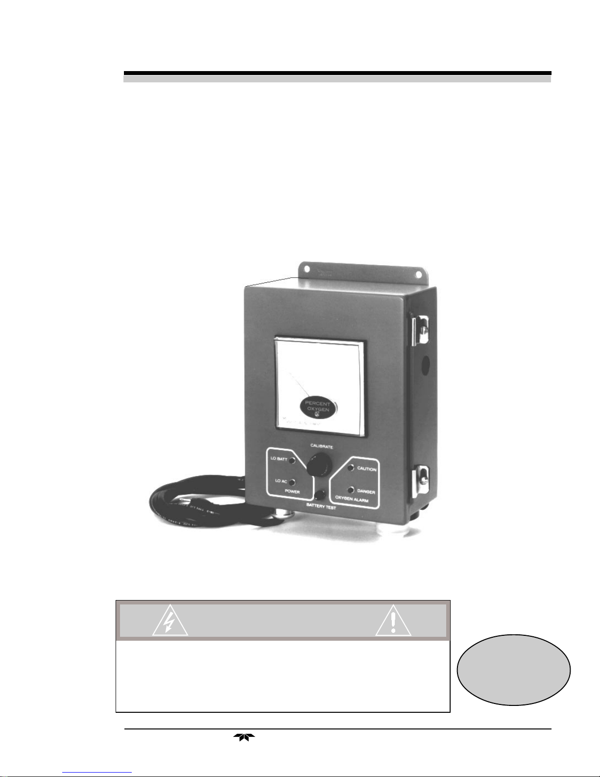
The Teledyne Analytical Instruments (TAI) Model 335 Oxygen
Alarm accurately measures the oxygen content of the atmosphere surrounding its sensor. The standard measurement range is 0-25% oxygen.
The alarm feature of the instrument incorporates two adjustable setpoints
to allow alarm warning under either of two independent oxygen level
conditions. The standard alarm indication is produced by both an audible
annunciator and a visual light, and when an alarm condition exists, a relay
is energized to switch a set of relay contacts. Both normally open and
normally closed circuits are provided by the Form “C” relay contacts;
consult the Interconnection Diagram at the rear of the manual to find the
interconnection terminals where the circuits can be accessed.
DANGER:
The instrument is designed as a safety monitor. However, it is the
responsibility of the user to establish whether or not the total system or
instrument, environment, alarm components and any other relevant devices
will actually assure safety in his/her particular circumstances.
The “Safety Checklist” outlined in the “Pre-Operation” section of this
manual should be treated as a guide only; it is up to the user to establish
practical safety precautions. Also, it is vital that operator’s understand and
test the operation of the complete system.
Consult the circuit-related drawings at the rear of the manual to find
information about circuit paths (schematic) and connecting points (wiring
and interconnection diagrams), as well as physical characteristics and
dimensions (outline diagram). These drawings reflect the exact design and
construction of your instrument.
Remove power from the system before opening the
instrument or attempting to perform any maintenance.
TELEDYNE ANALYTICAL INSTRUMENTS
1-1

1 Introduction Model 335
1-2
TELEDYNE ANALYTICAL INSTRUMENTS

Oxygen Alarm Monitor Operational Theory 2
Operational Theory
2.1 Method of Analysis
The analysis is specific for oxygen, i.e., the measuring cell will not
generate an output current unless oxygen is present in the sample gas.
Thus, the instrument has an absolute zero and no zero gas is required to
operate the analyzer.
The measuring cell has the ability to respond accurately to the presence of oxygen irrespective of flowrate. TAI recommends using ambient
air as a span gas or, if that is not possible, using a known calibration gas of
about 80% of the range of interest value.
The measuring cell (U.S. Patent #3,429,796) is a solid-state maintenance-free structure that carries a TAI guarantee for performance and usable
life. The cell consumes oxygen from the gas surrounding it and generates
a proportional microampere current. The low level signal is then amplified
by a solid-state operational amplifier. The resulting DC signal is suitable
for driving a high impedance recording device, a temperature compensation circuit for the cell and an integral 0-100µA meter. The output signal
is linear over the specified ranges of analysis.
2.2 Micro-Fuel Cell Sensor
2.2.1 Principles of Operation
The oxygen sensor used in the Model 335 is a Micro-Fuel Cell (MFC)
designed and manufactured by TAI. It is a sealed plastic disposable electrochemical transducer.
The active components of the MFC are a cathode, an anode and the
15% aqueous Potassium Hydroxide (KOH) electrolyte in which they are
immersed. The cell converts the energy from a chemical reaction into an
electrical potential that can produce a current in an external electrical
circuit. Its action is similar to that of a battery.
TELEDYNE ANALYTICAL INSTRUMENTS
2-1
2 Operational Theory Model 335
There is, however, an important difference in the operation of a
battery as compared to the MFC: in the battery, all reactants are stored
within the cell, whereas in the MFC, one of the reactants (oxygen) comes
from outside the device as a constituent of the sample gas being analyzed.
The MFC is therefore a hybrid between a battery and a true fuel cell. (All
of the reactants are stored externally in a true fuel cell.)
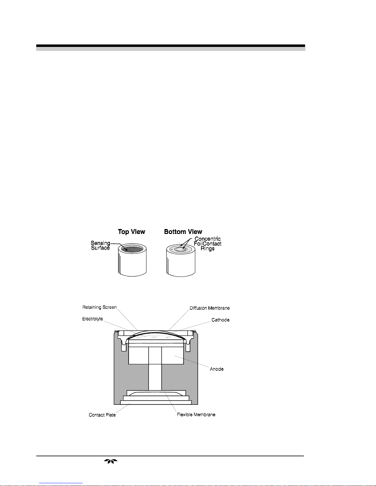
2.2.2 Anatomy of a Micro-Fuel Cell
The MFC is a cylinder only 1¼" in diameter and 1¼" thick. It is
made of extremely inert plastic (which can be placed confidently in practically any environment or sample stream) and is effectively sealed, though
one end is permeable to oxygen in the sample gas. At the permeable end a
screen retains a diffusion membrane through which the oxygen passes into
the cell. At the other end of the cell is a contact plate consisting of two
concentric foil rings. The rings mate with spring-loaded contacts in the
sensor block assembly and provide the electrical connection to the rest of
the analyzer. Figure 2-1 illustrates the external features.
mfcouts.wmf
Figure 2-1: Micro-Fuel Cell
mfc-xsec.wmf
Figure 2-2. Cross Section of a Micro-Fuel Cell
2-2
TELEDYNE ANALYTICAL INSTRUMENTS

Oxygen Alarm Monitor Operational Theory 2
At the top end of the cell, under the retaining screen, is a diffusion
membrane of Teflon whose thickness is very accurately controlled. (See
Figure 2-2.) Beneath the diffusion membrane lies the oxygen sensing
element (cathode) with a surface area almost 2.5cm2. The cathode has
many perforations to ensure sufficient wetting of the upper surface with
electrolyte, and it is plated with an inert metal.
The anode structure is below the cathode. It is made of lead and has a
proprietary design used to maximize the amount of metal available for
chemical reaction.
At the rear of the cell, just below the anode structure, is a flexible
membrane designed to accommodate the internal volume changes that
occur throughout the life of the cell. This flexibility preserves the integrity
of the structural elements surrounding the cathode and prevents the associated changes in electrical activity that would result.
The entire space between the diffusion membrane, above the cathode,
and the flexible rear membrane, beneath the anode, is filled with electrolyte. Cathode and anode are submerged in this common pool. They each
have a conductor connecting them to one of the external contact rings on
the contact plate on the bottom of the cell.
2.2.3 Electrochemical Reactions
The sample gas diffuses through the Teflon membrane. Any oxygen
in the sample gas is reduced on the surface of the cathode by the following
HALF REACTION:
O2 + 2H2O + 4e– → 4OH
–
(cathode)
(Four electrons combine with one oxygen molecule in the presence of
water from the electrolyte to produce four hydroxyl ions.)
When the oxygen is reduced at the cathode, lead is simultaneously
oxidized at the anode by the following HALF REACTION:
2(Pb + 2OH–) → 2(Pb+2 + H2O) + 4e
–
(anode)
(Two electrons are transferred for each atom of lead that is oxidized.
TWO ANODE REACTIONS balance one cathode reaction to transfer four
electrons.)
The electrons released at the surface of the anode flow to the cathode
surface when an external electrical path is provided. The current is proportional to the amount of oxygen reaching the cathode. It is measured and
used to determine the oxygen concentration in the gas mixture.
TELEDYNE ANALYTICAL INSTRUMENTS
2-3

2 Operational Theory Model 335
The overall reaction for the fuel cell is the SUM of the half reactions
above, or:
2Pb + O2 → 2PbO
(These reactions will hold as long as no gaseous components capable
of oxidizing lead are present in the sample. The only likely components
are the halogens: iodine, bromine, chlorine and fluorine.)
The output of the fuel cell is limited by (1) the amount of oxygen in
the cell at the time and (2) the amount of stored anode material.
In the absence of oxygen, no current is generated.
2.2.4 The Effect of Pressure
In order to state the amount of oxygen present in the sample as a
portion (parts-per-million {ppm} or percent {%}) of the gas mixture, it is
necessary that the sample diffuse into the cell under constant pressure.
If the pressure changes, the rate that oxygen reaches the cathode
through the diffusing membrane will also increase. The electron transfer,
and therefore the external current, will increase, even though the proportion of oxygen has not changed.
From Dalton's Law, the partial pressure of each gas in a mixture is the
same pressure that it would exert if it were alone given the same amount
and confined to the same volume. This means that as long as the total
pressure of the sample remains constant, the mixture can change, but the
diffusion of the oxygen will be affected only by the concentration of the
oxygen.
For this reason, the sample system supplying sample gas to the cell is
designed to keep the pressure on the diffusion membrane constant.
2.2.5 Calibration Characteristics
Given that the total pressure of the sample gas at the surface of the
MFC input is constant, a convenient characteristic of the cell is that the
current produced in an external circuit of constant impedance is directly
proportional to the rate at which oxygen molecules reach the cathode, and
this rate is directly proportional to the concentration of oxygen in the
gaseous mixture. In other words it has a linear characteristic curve, as
shown in Figure 2-3 (using arbitrary units). Measuring circuits do not have
to compensate for nonlinearities.
2-4
TELEDYNE ANALYTICAL INSTRUMENTS

Oxygen Alarm Monitor Operational Theory 2
mfccurve.wmf
Figure 2-3. Characteristic Input/Output Curve for a Micro-Fuel Cell
In addition, since there is zero output in the absence oxygen, the
characteristic curve has an absolute zero. The cell itself does not need to
be zeroed. In practical application, however, zeroing is still used to compensate for a number of other variables in the instrument and in the environment of the instrument.
2.3 Circuit Description
Follow this description on the Circuit Schematic in the Drawings
section at the rear of this document.
The measuring cell produces a current signal that is acted upon by the
thermistor, resistor and span potentiometer network to produce a temperature compensated voltage signal. The voltage signal (about 100mV 20%)
is applied to the CW terminal of the span pot (P1). A portion (about half)
of the voltage, as determined by the position of the span pot slider, is
applied to amplifier A1. Offset zero adjustment is provided at this point by
zero potentiometer P2. Capacitors C1 (RFI filter) and C2 (noise filter)
improve the signal quality to ensure clean amplification by A1. Adjustment of the span pot can now cause the signal voltage, amplified twentyfold by A1, to equal 1V full scale at the amplifier’s output.
The amplified 1V signal is fed to the meter, and a full scale meter
response with 1V applied is accomplished by adjustment of potentiometer
P6. Comparator sections A2a and A2b, biased by setpoint potentiometers
P5 and P4, respectively, provide direct activation of the alarm relays and
TELEDYNE ANALYTICAL INSTRUMENTS
2-5

2 Operational Theory Model 335
LED’s; they also enable the oscillator of the audible (beeper) alarm. The
alarm relays themselves are ultra-sensitive and require only a few
milliamps driving current. Jumpers A through H and J through R allow the
alarms to be connected in either LOW or HIGH configuration. The reference voltage for the alarm comparators is taken from the reference comparator circuit (which also monitors the battery and AC line voltage levels.)
Comparator sections A2c and A2d compare the battery voltage and a
voltage corresponding to the AC line voltage with a 1V reference level
produced by A1b from D7 and P3. To represent the line voltage, the
secondary of the power transformer and a voltage divider are used. If
either the battery voltage or the AC line voltage drop below relative preset
levels, the appropriate LED will light. Low voltage LED signals must be
acknowledged and the problem corrected as soon as possible; eventually,
the battery voltage will weaken to the point that the LED’s cease to warn
of the problem.
The 1V reference is also applied to the two alarm setpoint networks
consisting of P4/P19 (CAUTION SET) and R20/P5/R21 (DANGER SET),
which supply the reference voltages for the two alarm comparators. The
positions of the sliders of setpoint potentiometers P4 and P5 determine the
reference levels of the two comparators, and consequently provide the
setpoints of the two alarms.
2.4 Alarms
When the alarm setpoints are properly adjusted, they provide an
operational band that covers all acceptable oxygen concentrations. If the
oxygen level at the sensor crosses the adjusted setpoint of one of the
alarms, that alarm will cause the switching of relay contacts. Normally
open (N.O.) and normally closed (N.C.) circuit connections at the interconnection terminal strip will be reversed. Thus, a circuit that is open (turned
off) in a non-alarm condition will be closed (turned on) when its alarm is
activated, and vice-versa.
As per OSHA specifications, the standard factory setting of the two
alarms provides a “CAUTION” alarm at 20% oxygen (at the sensor) and a
“DANGER” alarm at 19.5% oxygen. To cover special cases, a limited
amount of adjustment is possible.
2-6
TELEDYNE ANALYTICAL INSTRUMENTS

Oxygen Alarm Monitor Installation and Operation 3
Installation and Operation
Installation consists of installing the Micro-Fuel Cell, installing the
rechargeable batteries and connecting the instrument to the AC power.
3.1 Installing the Micro-Fuel Cell
The Micro-Fuel Cell is shipped separately from the instrument and must
be installed before operating the instrument. Turn the instrument off and
disconnect the AC power.
To install the cell in the probe assembly:
1. Remove the probe from its holder inside the instrument case and
remove the cell from its sealed shipping package.
2. Unscrew the cap from the top of the probe assembly.
3. Remove the shorting clip from the cell. REMOVE THE
MEMBRANE END OF THE SHORTING CLIP FIRST so that
it does not puncture the soft membrane.
4. Place the cell in the probe with the terminal end facing down
toward the probe contacts and the soft membrane surface facing
the outside.
5. Replace the probe cap, making sure that it is all the way down
and seated on the probe body, then replace the probe assembly
into its holder.
3.2 Power and Signal Connections
NOTE: Batteries are shipped disconnected.
Refer to manual for connection before operation.
This instrument is designed to operate from a 115VAC @ 50/60 Hz
power. As an option, if specified at the time of purchase, this instrument can
be powered from 100 or 220VAC @ 50/60 Hz. Connect the included
power cord to the AC power.
3.2.1 AC and Battery Backed Standby Power
TELEDYNE ANALYTICAL INSTRUMENTS
3-1

3 Installation and Operation Model 335
The Model 335 uses battery backed standby power during periods of
power failure or "brown out" conditions. Power outages will not interfere
with a properly-working Model 335 oxygen alarm if it is installed and used
correctly. The standby power source uses rechargeable NiCad (Nickel
Cadmium) batteries. If the AC power is temporarily impaired (“brown-out”)
or interrupted, the stand-by power supply takes over and keeps the analyzer
in operation.
Periodically test the condition of the battery pack by pressing the
“BATTERY TEST” pushbutton on the instrument’s control panel and note
the battery condition in the area so designated on the meter scale. Release
the pushbutton to return to the normal sampling mode. The battery test
provides only an indication of the battery state under the test conditions; it is
possible that a battery might test well but perform for only a short time under
actual operational conditions (a characteristic of the battery, not the analyzer), so it is very important that power outages be corrected without delay.
Furthermore, TAI recommends that the instrument be tested periodically by
operating it for several hours without AC power (that is, under battery
power).
The standard Model 335 is designed to operate on standby battery
power for at least six hours if conditions are favorable, i.e., conditions are not
extreme and the batteries are well charged and in good condition). Under
actual conditions, however, these factors will always tend to evolve toward
the worst case if left unattended. Therefore, the user must always ensure that
battery condition, charge and other related factors are monitored with sufficient frequency to prevent problems. Most importantly, DO NOT DEPEND
UPON THE LONGEVITY OF BATTERY BACKUP, but correct problems as soon as possible.
3.2.2 Installing the Rechargeable NiCad Batteries
Connect the batteries as follows:
1. Remove the tape from the red wire and the white green wire.
2. Connect the red wire to TS2-5; connect the white green wire to
TS2-6.
3.2.3 Signal Connections
Alarm relay and optional output signals are available to the user from a
terminal block inside the enclosure. See the Interconnection Diagram included with the drawings at the back of this manual.
3-2
TELEDYNE ANALYTICAL INSTRUMENTS

Oxygen Alarm Monitor Installation and Operation 3
The CAUTION and DANGER alarms are equipped with separate
relays. Each of these relays provides a single set of contacts rated for 2A
resistive load @ 28VDC or 2A @ 120VAC.
A 0-1VDC signal output is available as an option that must be specified
at the time of purchase. If you have chosen this option, the Oxygen Monitor
will generate a 0-1VDC signal as output to represent the 0-25% oxygen
range. This output signal is linear and proportional to the oxygen concentration within the 0-25% range. The output signal is available to the user from
a terminal block inside the enclosure. (See the Interconnection Diagram
included with the drawings at the rear of this document.)
3.3 Calibration
Prior to operating this instrument for the first time, the Oxygen Monitor
must be calibrated. If this instrument is to be used as a safety monitor,
routine calibration should be carried out on a weekly basis.
NOTE:
Calibration of a standard instrument is performed by exposing the
sensor to ordinary ambient air (not the monitored atmosphere) and adjusting
the “CALIBRATE” control until the meter pointer rests at the CAL mark on
its scale. This mark represents the normal oxygen concentration of air
(20.9%) under standard conditions, so be sure that the sensor is exposed to
fresh air when using the calibration mark.
If it is not feasible to use ordinary air as the calibration gas, then clean,
compressed instrument air can be used. It will probably be necessary to seal
the sensor in the piped-in calibration gas to isolate it from the surrounding
atmosphere. A flow-through adaptor can be purchased from TAI as an
accessory for those applications. Although a special calibration gas can be
used, the calibration results will be meaningless unless the oxygen concentration of the calibration gas is known, and the analyzer is adjusted to indicate
that concentration. To eliminate any error caused by the calibration gas,
always use a certified composition with an oxygen concentration between
80% and 90% of the full scale meter reading of the analyzer.
Calibration in the same atmosphere that is being monitored can
result in serious error. The analysis performed and the alarms, if
any, generated by this instrument when calibrated using the monitored atmosphere or a span gas of unknown composition, will be
meaningless.
Once the instrument has been installed, calibrated, and the power turned
on, it will continuously monitor the oxygen level within the environment it is
3.4 Operation
TELEDYNE ANALYTICAL INSTRUMENTS
3-3

3 Installation and Operation Model 335
placed. The oxygen level is displayed on the analog meter. The response
time of the instrument will depend on the actual Micro-Fuel Cell (MFC)
installed. With the class B-3 MFC installed, the response time is less than 15
seconds at 25°C. The table below indicates the response time for some
MFCs typically used in the Model 335.
Class Response Warranty Application
Time (Sec) (Months)
B-3 13 12 Intermediate response/long life
B-5 13 18 Long life/general O2 monitoring
C-3 30 12 General purpose/long life
3.5 Cell Warranty
The Class B-3 cell used in the Model 335 is warranted for 12 months of
service. Under normal operating conditions the Class B-3 cell should last 12
months in air. For special applications, optional cells are available.
NOTE:
Customers having warranty claims must return the cell in question to
the factory evaluation after obtaining an RMA number. If it is determined
that failure is due to faulty workmanship or materials, the cell will be replaced free of charge. If a cell was working satisfactorily, but fails short of
its warranty period, the customer will receive credit, on a prorated basis,
toward the purchase of a new cell.
Evidence of mishandling will render the cell warranty null and
void.
3.6 Safety Checklist
The following checklist is offered only as a guide to assist the user in
verifying a number of important factors; it is by no means a complete list of
safety-related items. The procedures and precautions relating to the use of
the instrument in the user’s process must be developed by the user. It is vital
that the operator understand and test the operation of the total system.
Verify that:
1. Instrument power is active and adequate.
3-4
TELEDYNE ANALYTICAL INSTRUMENTS

Oxygen Alarm Monitor Installation and Operation 3
2. Instrument functions are operational.
3. Alarm indicators are effective and produce intended results.
4. Unauthorized personnel are prevented from tampering with the
instrument or auxiliary equipment.
5. Routine test and calibration procedures are instituted and
followed.
6. Any and all sampling and/or location problems are identified and
handled.
7. Any and all necessary warning labels, notices, and information
are provided.
8. Operators understand the operations and functions of the analyzer
and system.
9. Any environmental or other influences that could affect the
operation or accuracy of the instrument are identified and
handled.
3.7 Accessory Flow-Through Adapter
A flow-through adaptor is available for the Series 335 Oxygen Analyzer for those applications that require piped-in gases. The adaptor consists
of a sealed chamber where the instrument’s probe is inserted, with two
radially-oriented hose connectors to which supply and vent lines for the
calibration gas are connected. The design provides gas flow over the sensing surface of the cell without contamination by the surrounding monitored
atmosphere.
TELEDYNE ANALYTICAL INSTRUMENTS
3-5

3 Installation and Operation Model 335
3-6
TELEDYNE ANALYTICAL INSTRUMENTS

Oxygen Alarm Monitor Appendix
Appendix
Specifications
Range: 0-25% Oxygen
Sensitivity: 0.5% of full scale
Accuracy: ±2% of full scale (at constant temperature)
±5% of full scale (over operating temperature
range once the system has equilibrated)
Response Time: 90% in less than 15 seconds at 25°C (B-3 cell)
Operating Temperature: 15-45°C
Reproducibility: ± 1% of full scale
Sensor Type: B-3, B-5, C-3
Readout: High resolution 41/2" analog meter
Battery Life: 48 hours (non-alarm condition)
Power Requirements: 115VAC @ 50/60 Hz charges and maintains on
trickle charge two NiCad battery packs.
Enclosure: Dust-tight steel enclosure (wall mountable, two
brackets top and bottom, each with two 5/16"
holes, 8" center-to-center).
11.5"(H) x 9"(W) x 4.125"(D)
(22.9cm x 29.2cm x 10.4cm)
Weight: 11.7lbs (5.3Kg)
Alarms: Factory Set: CAUTION = 20.0%
DANGER = 19.5%
Audible Horn
Visual Red Indicator Lamps
TELEDYNE ANALYTICAL INSTRUMENTS
A-1

Appendix Model 335
Recommended Spare Parts List
Qty P/N Description
1 C-6689 Micro-Fuel Cell, Class B-3 (if non-standard,
see "Specifications" Sheet)
4 B-76 Battery
1 M-69 Meter
1 F-8 Fuse, 1/2A Slo-Blo
1 L-52 Indicator Light (Red)
1 A-20 Alarm, Sonalert
1 P-102 Span Potentiometer
1 R-914 Relay
2 S-521 Spring, Relay Hold-Down
IMPORTANT: Orders for replacement parts should include the part
number, the model and serial numbers of the analyzer
in which they are to be used.
Orders should be sent to:
TELEDYNE ANALYTICAL INSTRUMENTS
16830 Chestnut Street
City of Industry, CA 91749-1580
Phone (626)961-1500,
Fax (626)961-2538
TWX (910)584-1887 TDYANLY COID or your local representative.
Web: www.teledyne-ai.com
Drawing List
C-24634 Outline Drawing
A-24690 Interconnection Diagram
B-24663 Schematic Diagram
C-24694 Wiring Diagram
A-2
TELEDYNE ANALYTICAL INSTRUMENTS

Oxygen Alarm Monitor Appendix
Material Safety Data Sheet
Section I – Product Identification
Product Name: Micro-Fuel Cells and Super Cells, all classes except
A-2C, A-3, and A-5.
Electrochemical Oxygen Sensors, all classes except R-19.
Mini-Micro-Fuel Cells, all classes.
Manufacturer: Teledyne Analytical Instruments
Address: 16830 Chestnut Street, City of Industry, CA 91749
Phone: (626) 934-1500
Technical Support: (626) 934-1673
Environment Health
and Safety: (626) 934-1592
Section II – Hazardous Ingredients/Composition
Material or
Component C.A.S. # Quantity OSHA PEL ACGIH
TLV
Lead (Pb) 7439-92-1 3–20 gms 0.05 mg/m30.15 mg/m
Potassium Hydroxide 1310-58-3 1–5 ml None 2 mg/m
Solution 15% (KOH)
Section III – Physical/Chemical Characteristics
Material
Appearance
or Component
Lead
Boiling
Point (°C)
1744
Specific
Gravity
11.34
Vapor
Pressure
na
Melting
Point
(°C)
328
Density
na
Evap.
Rate
na
Solubility
in Water
Insoluble
3
3
Odor
Solid, silver
gray, odorless
1320
Potassium
Hydroxide
2.04
na
na
na
TELEDYNE ANALYTICAL INSTRUMENTS
360
Complete
White or
slightly
yellow,
no odor
A-3

Appendix Model 335
Section IV – Fire and Explosion Hazard Data
Flash Point: na Flammable Limits: na LEL: na UEL: na
Extinguishing Media: Use extinguishing media appropriate to surrounding fire
conditions. No specific agents recommended.
Special Fire Fighting
Equipment:
Wear NIOSH/OSHA approved self-contained breathing
apparatus and protective clothing to prevent contact with
skin and eyes.
Unusual Fire and Explosion
Hazards:
Emits toxic fumes under fire conditions.
Section V – Reactivity Data
Stability: Stable
Incompatibilities: Aluminum, organic materials, acid chlorides, acid
anhydrides, magnesium, copper. Avoid contact with acids
Hazardous Decomposition of
Byproducts:
Hazardous Polymerization: Will not occur.
and hydrogen peroxide > 52%.
Toxic fumes
Section VI – Health Hazard Data
Routes of Entry: Inhalation: Highly unlikely
Ingestion: May be fatal if swallowed.
Skin: The electrolyte (potassium hydroxide) is corrosive; skin
contact may cause irritation or chemical burns.
Eyes: The electrolyte (potassium hydroxide) is corrosive; eye
contact may cause irritation or severe chemical burns.
Acute Effects: The electrolyte is harmful if swallowed, inhaled or
Chronic Effects: Prolonged exposure with the electrolyte has a destructive
A-4
TELEDYNE ANALYTICAL INSTRUMENTS
adsorbed through the skin. It is extremely destructive to
tissue of the mucous membranes, stomach, mouth, upper
respiratory tract, eyes and skin.
effect on tissue.
Chronic exposure to lead may cause disease of the blood
and blood forming organs, kidneys and liver, damage to
the reproductive systems and decrease in fertility in men
and women, and damage to the fetus of a pregnant
woman. Chronic exposure from the lead contained in
this product is extremely unlikely.

Oxygen Alarm Monitor Appendix
Signs and Symptoms of
Exposure:
Carcinogenicity: Lead is classified by the IARC as a class 2B carcinogen
OSHA: Where airborne lead exposures exceed the OSHA action
NTP: na
Medical Conditions Generally
Aggravated by Exposure:
Emergency First Aid Procedures:
Contact of electrolyte with skin or eyes will cause a
burning sensation and/or feel soapy or slippery to touch.
Other symptoms of exposure to lead include loss of
sleep, loss of appetite, metallic taste and fatigue.
(possibly carcinogenic to humans)
level, refer to OSHA Lead Standard 1910.1025.
Lead exposure may aggravate disease of the blood and
blood forming organs, hypertension, kidneys, nervous
and possibly reproductive systems. Those with preexisting skin disorders or eye problems may be more susceptible to the effects of the electrolyte.
In case of contact with the skin or eyes, immediately
flush with plenty of water for at least 15 minutes and
remove all contaminated clothing. Get medical attention
immediately.
If ingested, give large amounts of water and DO NOT
INDUCE VOMITING. Obtain medical attention immediately.
If inhaled, remove to fresh air and obtain medical
attention immediately.
Section VII – Precautions for Safe Handling and Use
NOTE: The oxygen sensors are sealed, and under normal circumstances,
the contents of the sensors do not present a health hazard. The
following information is given as a guide in the event that a cell
leaks.
Protective measures
during cell replacement:
Cleanup Procedures: Wipe down the area several times with a wet paper
Before opening the bag containing the sensor cell, check
the sensor cell for leakage. If the sensor cell leaks, do
not open the bag. If there is liquid around the cell while
in the instrument, wear eye and hand protection.
towel. Use a fresh towel each time. Contaminated paper
towels are considered hazardous waste.
TELEDYNE ANALYTICAL INSTRUMENTS
A-5

Appendix Model 335
Section VIII – Control Measures
Eye Protection: Chemical splash goggles
Hand Protection: Rubber gloves
Other Protective Clothing: Apron, face shield
Ventilation: na
Section IX – Disposal
Both lead and potassium hydroxide are considered poisonous substances and are regulated under
TSCA and SARA Title III.
EPA Waste Number: D008
California Waste Number: 181
DOT Information: RQ Hazardous Waste Solid N.O.S. (Lead), 9, UN3077,
PG III
Follow all Federal, State and Local regulations.
Section X – References
Material Safety Data Sheets from J.T. Baker Chemical, Aldrich, Malinckrodt, ASARCO
U.S. Department of Labor form OMB No. 1218-0072
Title 8 California Code of Regulations
TSCA
SARA Title III
CFR 49
CFR 29
CFR 40
NOTE: The above information is believed to be correct and is offered for your
information, consideration, and investigation. It should be used as a
guide. Teledyne Analytical Instruments shall not be held liable for any
damage resulting from handling or from contact with the above product.
A-6
TELEDYNE ANALYTICAL INSTRUMENTS
 Loading...