

Page 1
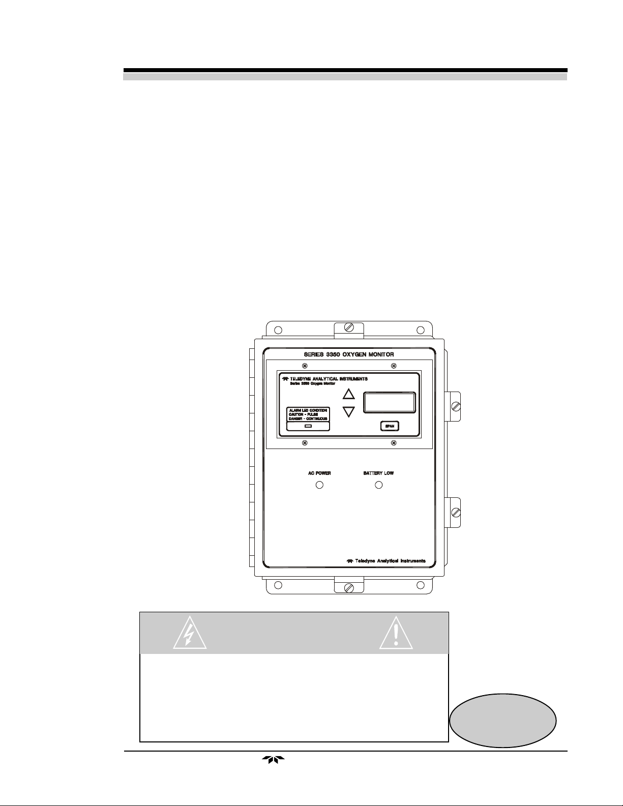
OPERATING INSTRUCTIONS FOR
Model 3350
Oxygen Alarm Monitor
DANGER
HIGHLY TOXIC AND OR FLAMMABLE LIQUIDS OR GASES MAY BE PRESENT IN THIS
MONITORING SYSTEM.
PERSONAL PROTECTIVE EQUIPMENT MAY BE REQUIRED WHEN SERVICING THIS SYSTEM.
HAZARDOUS VOLTAGES EXIST ON CERTAIN COMPONENTS INTERNALLY WHICH MAY
PERSIST FOR A TIME EVEN AFTER THE POWER IS TURNED OFF AND DISCONNECTED.
ONLY AUTHORIZED PERSONNEL SHOULD CONDUCT MAINTENANCE AND/OR SERVICING.
BEFORE CONDUCTING ANY MAINTENANCE OR SERVICING CONSULT WITH AUTHORIZED
SUPERVISOR/MANAGER.
Teledyne Analytical Instruments
P/N M70682
4/11/2014
i
Page 2

Copyright © 2000Teledyne Analytical Instruments
All Rights Reserved. No part of this manual may be reproduced, transmitted, transcribed, stored in a retrieval system, or translated into any other language or computer
language in whole or in part, in any form or by any means, whether it be electronic,
mechanical, magnetic, optical, manual, or otherwise, without the prior written consent of
Teledyne Analytical Instruments, 16830 Chestnut Street, City of Industry, CA 9174
Warranty
This equipment is sold subject to the mutual agreement that it is warranted by us free
from defects of material and of construction, and that our liability shall be limited to
replacing or repairing at our factory (without charge, except for transportation), or at
customer plant at our option, any material or construction in which defects become
apparent within one year from the date of shipment, except in cases where quotations or
acknowledgements provide for a shorter period. Components manufactured by others bear
the warranty of their manufacturer. This warranty does not cover defects caused by wear,
accident, misuse, neglect or repairs other than those performed by Teledyne or an authorized service center. We assume no liability for direct or indirect damages of any kind and
the purchaser by the acceptance of the equipment will assume all liability for any damage
which may result from its use or misuse.
We reserve the right to employ any suitable material in the manufacture of our
apparatus, and to make any alterations in the dimensions, shape or weight of any parts, in
so far as such alterations do not adversely affect our warranty.
8.
Important Notice
This instrument provides measurement readings to its user, and serves as a tool by
which valuable data can be gathered. The information provided by the instrument may
assist the user in eliminating potential hazards caused by his process; however, it is
essential that all personnel involved in the use of the instrument or its interface, with the
process being measured, be properly trained in the process itself, as well as all instrumentation related to it.
The safety of personnel is ultimately the responsibility of those who control process
conditions. While this instrument may be able to provide early warning of imminent danger,
it has no control over process conditions, and it can be misused. In particular, any alarm or
control systems installed must be tested and understood, both as to how they operate and
as to how they can be defeated. Any safeguards required such as locks, labels, or redundancy, must be provided by the user or specifically requested of Teledyne at the time the
order is placed.
Therefore, the purchaser must be aware of the hazardous process conditions. The
purchaser is responsible for the training of personnel, for providing hazard warning
methods and instrumentation per the appropriate standards, and for ensuring that hazard
warning devices and instrumentation are maintained and operated properly.
Teledyne Analytical Instruments (TAI), the manufacturer of this instrument,
cannot accept responsibility for conditions beyond its knowledge and control. No statement expressed or implied by this document or any information disseminated by the
manufacturer or its agents, is to be construed as a warranty of adequate safety control
under the user’s process conditions.
ii
Teledyne Analytical Instruments
Page 3
.
Model 3350 complies with all of the requirements of the Commonwealth of Europe (CE) for Radio Frequency Interference, Electromagnetic Interference (RFI/EMI), and Low Voltage Directive
(LVD).
The following International Symbols are used throughout the Instruction Manual for your visual and immediate warnings and when you
have to attend CAUTION while operating the instrument:
GROUND
Protective Earth
CAUTION, The operator needs to refer to the manual
for further information. Failure to do so may
compromise the safe operation of the equipment.
CAUTION, Risk of Electric Shock
Teledyne Analytical Instruments
iii
Page 4

Contents
Introduction
1.1 Overview........................................................................ 1-1
1.2 Main Features of the Analyzer ....................................... 1-1
1.3 Front Panel Description.................................................. 1-2
1.4 Rear Panel Description.................................................. 1-3
Operational Theory
2.1 Introduction .................................................................... 2-1
2.2 Micro-Fuel Cell Sensor .................................................. 2-1
2.2.1 Principles of Operation .......................................... 2-1
2.2.2 Anatomy of a Micro-Fuel Cell................................. 2-2
2.2.3 Electrochemical Reactions .................................... 2-3
2.2.4 The Effect of Pressure............................................ 2-3
2.2.5 Calibration Characteristics ...................................... 2-4
2.3 Electronics ..................................................................... 2-5
2.3.1 General.................................................................. 2-5
2.3.2 Signal Processing .................................................. 2-5
2.4 Alarms............................................................................ 2-6
Installation
3.1 Unpacking the Analyzer................................................. 3-1
3.2 Installation...................................................................... 3-2
3.3 Installing the Micro-Fuel Cell ......................................... 3-2
3.4 Electrical Connections ................................................... 3-2
3.5 Power and Signal Connections ...................................... 3-3
3.6 Calibration ..................................................................... 3-8
3.7 Operation ....................................................................... 3-9
3.8 Cell Warranty ................................................................. 3-10
3.9 Safety Checklist ............................................................. 3-10
iv
3.5.1 AC and Battery Backed Standby Power ................ 3-3
3.5.2 Battery Backed Standby Power ............................. 3-4
3.5.2.1 Connecting the Rechargeable Battery ..... 3-5
3.5.3 Analog Outputs ...................................................... 3-6
3.5.4 RS-232 Port (optional) ........................................... 3-6
3.5.5 Alarm Relays ......................................................... 3-7
Teledyne Analytical Instruments
Page 5

3.10 Accessory Flow-Through Adapter ................................. 3-11
Operation
4.1 Using the Function and Data Entry Buttons ................... 4-1
4.2 Alarm Conditions ........................................................... 4-2
4.3 Calibration ..................................................................... 4-2
Maintenance
5.1 Replacing the Fuse........................................................ 5-1
5.1.1 Standard AC Version ............................................. 5-1
5.1.2 AC with Battery Backup Version ............................ 5-2
5.2 Sensor Installation or Replacement ............................... 5-2
5.2.1 When to Replace a Sensor.................................... 5-2
5.2.2 Ordering and Handling of Spare Sensors .............. 5-3
5.2.3 Removing the Micro-Fuel Cell ............................... 5-3
5.2.4 Installing a Micro-Fuel Cell .................................... 5-4
5.2.5 Cell Warranty Conditions ....................................... 5-4
Appendix
A.1 Specifications ................................................................ A-1
A.2 Spare Parts List ............................................................. A-2
A.3 Reference Drawing........................................................ A-3
A.4 Miscellaneous................................................................ A-3
Teledyne Analytical Instruments
v
Page 6

D ANGER
COMBUSTIBLE GAS USAGE WARNING
This is a general purpose instrument designed for usage in a
nonhazardous area. It is the customer's responsibility to ensure
safety especially when combustible gases are being analyzed
since the potential of gas leaks always exist.
The customer should ensure that the principles of operating of
this equipment is well understood by the user. Misuse of this
product in any manner, tampering with its components, or unauthorized substitution of any component may adversely affect
the safety of this instrument.
Since the use of this instrument is beyond the control of
T eledyne, no responsibility by T eledyne, its affiliates, and a gents
for damage or injury from misuse or neglect of this equipment is
implied or assumed.
vi
Teledyne Analytical Instruments
Page 7

Alarm Oxygen Monitor Introduction 1
Introduction
1.1 Overview
The Teledyne Electronic Technologies Analytical Instruments (TET/AI)
Model 3350 is a microprocessor-based Oxygen Alarm Monitor for real-time
measurement of the oxygen content of the atmosphere surrounding its sensor.
The Model 3350 standard instrument is configured to run from an AC
power source and is also available with continuous charging, DC battery backup
option. The rated battery life is approximately 17 hours configured in failsafe
mode and 48 hours in non-failsafe mode.
The instrument is designed as a safety monitor. However, it is the responsibility of the user to establish whether or not the total system or instrument,
environment, alarm components and any other relevant devices will actually
assure safety in his/her particular circumstances.
1.2 Main Features of the Analyzer
• Accurate readings of oxygen content at the standard 0-25% range.
(Consult factory for other ranges)
• Large, bright, light emitting diode meter readout.
• Nylon cell holder.
• Simple pushbutton span controls.
• Advanced Micro-fuel Cell, for percent analysis, has a 12 month
warranty.
• Unaffected by oxidizing gasses.
• Fast response and recovery time.
• Microprocessor based electronics: 8bit CMOS microprocessor with
on-board RAM and 16KB ROM.
• Air calibration range for convenient spanning at 20.9% oxygen.
Teledyne Analytical Instruments
1-1
Page 8
1 Introduction Model 3350
• Two factory preset alarms, form C relay contacts, configured as Failsafe
or Non-Failsafe.
• Sensor failure alarm, form C relay contact, configured as Failsafe or
Non-Failsafe.
• Three analog outputs: two for measurement (0–10 VDC, and
negative ground 4–20 mADC) and one for range identification
(0-10 VDC).
• Optional RS232
• Compact and rugged, wall mounted NEMA-4 rated enclosure.
• CE Approval
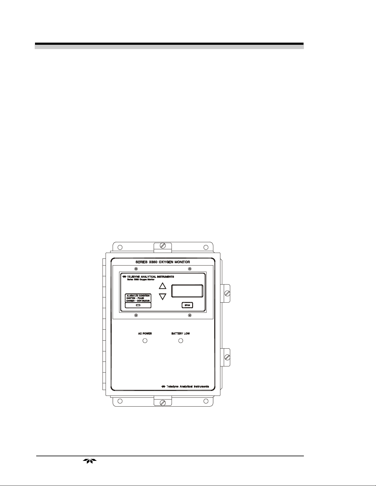
1.3 Front Panel Description
All controls and displays except the power switch are accessible from the
front panel. See Figure 1-1. The front panel has three pushbutton membrane
switches, a digital meter, and an alarm indicator LED for operating the monitor.
These features are described briefly here and in greater detail in Chapter 4,
Operation.
1-2
Figure 1-1: Front Panel
Span Key: Pushbutton membrane switch is used to span calibrate the ana-
lyzer:
Teledyne Analytical Instruments
Page 9
Alarm Oxygen Monitor Introduction 1
Data Entry Keys: Two pushbutton membrane switches are used to
manually change the span measurement parameters of the instrument as they are
displayed on the LED meter readout:
• Up Arrow Increment values of parameters upwards as they
are displayed on the LED readout.
• Down Arrow Increment values of parameters downwards as
they are displayed on the LED readout.
Digital LED Readout: The digital display is a LED device that
produces large, bright, 7-segment numbers that are legible in any lighting
environment. It has three functions:
• Meter Readout: As the meter readout, it displays the oxygen
concentration currently being measured.
• Measurement Parameters Readout: It displays the span
calibration point when it is being checked or changed.
• Alarm Condition: It displays intermittently, “CAUt” and the gas
readings when a CAUTION Alarm has been initiated and “dAng”
for DANGER Alarm.
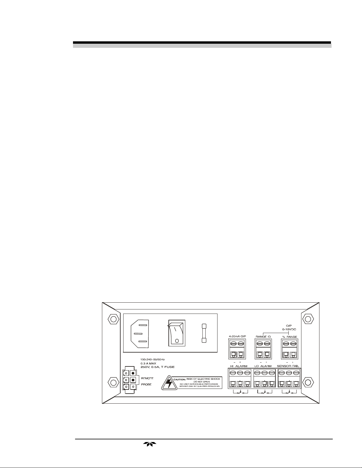
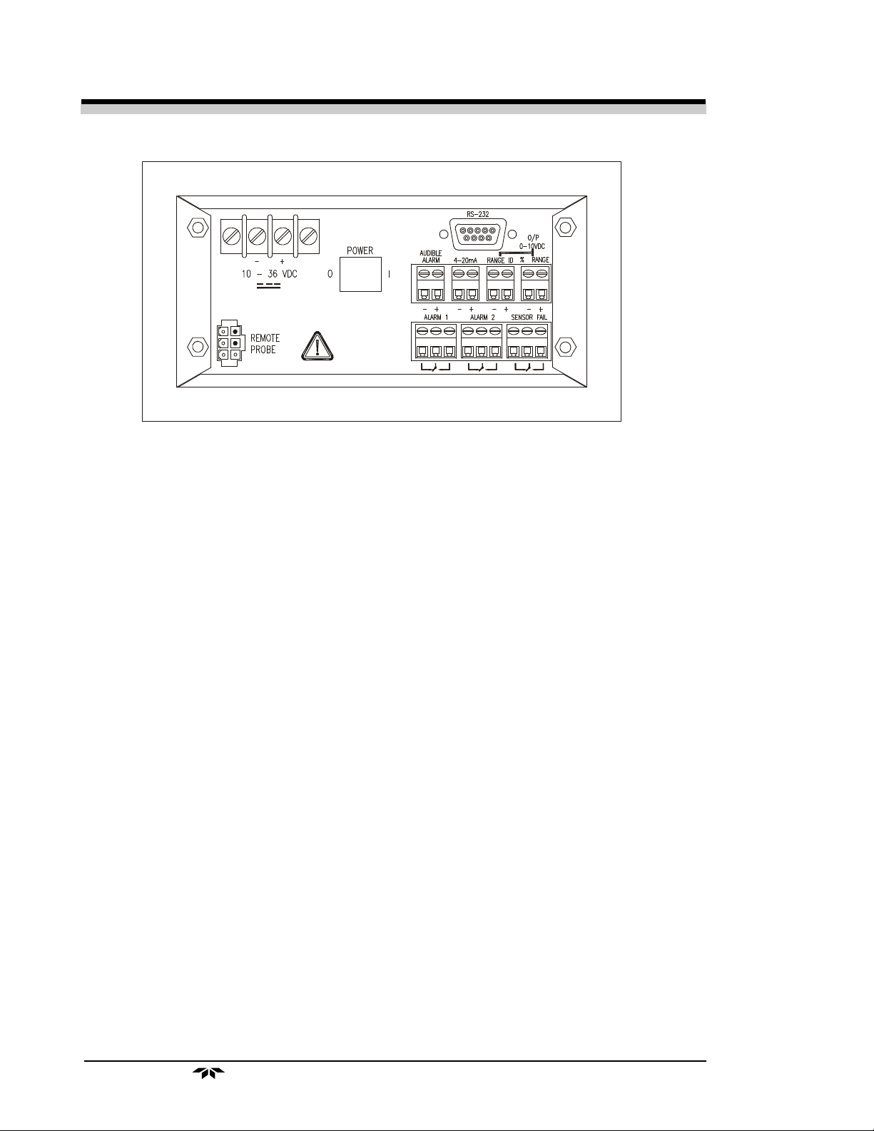
1.4 Rear Panel Description
The rear panel contains the electrical input and output connectors. Separate rear panel illustrations are shown in figure 1-2 for the AC and DC battery
backup versions of the instrument. The connectors are described briefly here
and in detail in the Installation chapter of this manual.
Figure 1-2 Rear Panel, Control Unit - AC
(viewed from inside front door)
Teledyne Analytical Instruments
1-3
Page 10
1 Introduction Model 3350
Figure 1-2 Rear Panel, Control Unit - DC
(viewed from inside front door)
• Power Connection AC version: Universal 100–240 VAC, at
50/60Hz. The connector housing includes
the fuse holder and the power switch.
DC Battery Backup Version: , 10 to 36
VDC. Supplied by universal 100-240VAC.
Fuse Holder: Replacing the fuses is
described in Chapter 5, Maintenance.
I/O Power Switch: Turns the instrument
power ON (1) or OFF (0).
• Analog Outputs 0–10 VDC concentration output.
0–10 VDC range ID (or optional
overrange) output.
4–20 mA DC concentration output,
negative ground.
• Digital Output RS232 (optional).
• Audible Alarm Output for standard internal or customer
supplied external audible alarm
(12VDC@5mA).
• Alarm Connections Alarm 1 (CAUTION), Alarm 2
(DANGER), and Sensor Failure Alarm
connections.
1-4
• Sensor Connector Sensor Connector.
Teledyne Analytical Instruments
Page 11

Alarm Oxygen Monitor Operational Theory 2
Operational Theory
2.1 Introduction
The analysis is specific for oxygen, i.e., the measuring cell will not generate
an output current unless oxygen is present in the sample gas. Thus, the instrument
has an absolute zero and no zero gas is required to operate the analyzer.
The measuring cell has the ability to respond accurately to the presence of
oxygen irrespective of flowrate. TAI recommends using ambient air as a span
gas or, if that is not possible, using a known calibration gas of about 80% of the
range of interest value.
The measuring cell (U.S. Patent #3,429,796) is a solid-state maintenancefree structure that carries a TAI guarantee for performance and usable life. The
cell consumes oxygen from the gas surrounding it and generates a proportional
microampere current. The Control Unit processes the sensor output and translates it into electrical concentration, range, and alarm outputs, and a percent
oxygen meter readout. It contains a microcontroller that manages all signal
processing, input/output, and display functions for the analyzer.
2.2 Micro-Fuel Cell Sensor
2.2.1 Principles of Operation
The oxygen sensor used in the Model 3350 is a Micro-fuel Cell designed
and manufactured by TAI. It is a sealed, disposable electrochemical transducer.
The active components of the Micro-Fuel Cell are a cathode, an anode,
and the aqueous KOH electrolyte in which they are immersed. The cell converts
the energy from a chemical reaction into an electrical potential that can produce a
current in an external electrical circuit. Its action is similar to that of a battery.
There is, however, an important difference in the operation of a battery as
compared to the Micro-Fuel Cell: In the battery, all reactants are stored within
the cell, whereas in the Micro-Fuel Cell, one of the reactants (oxygen) comes
from outside the device as a constituent of the sample gas being analyzed. The
Micro-Fuel Cell is therefore a hybrid between a battery and a true fuel cell. (All
of the reactants are stored externally in a true fuel cell.)
Teledyne Analytical Instruments
2-1
Page 12
2 Operational Theory Model 3350
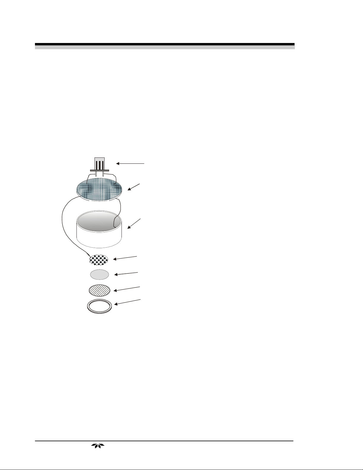
2.2.2 Anatomy of a Micro-Fuel Cell
The Micro-Fuel Cell is made of extremely inert plastic (which can be
placed confidently in practically any environment or sample stream). It is effectively sealed, though one end is permeable to oxygen in the sample gas. At the
permeable end a screen retains a diffusion membrane through which the oxygen
passes into the cell. At the other end of the cell is a connector and temperature
compensation network (restrictors and thermistor) on a printed circuit board.
Refer to Figure 2-1, Basic Elements of a Micro-Fuel Cell, which illustrates the following internal description.
Electrical Connector
Circuit Board
with temperature compensation network.
Anode
Cathode
Teflon Membran e
Screen
Clamp
Figure 2-1. Basic Elements of a Micro-Fuel Cell (not to scale)
At the sensing end of the cell is a diffusion membrane, whose thickness is
very accurately controlled. Near the diffusion membrane lies the oxygen sensing
element—the cathode.
The anode structure is larger than the cathode. It is made of lead and is
designed to maximize the amount of metal available for chemical reaction.
The space between the active elements is filled by a structure saturated with
electrolyte. Cathode and anode are wet by this common pool. They each have a
conductor connecting them, through some electrical circuitry, to one of the
external contacts in the connector receptacle, which is on the top of the cell.
2-2
Teledyne Analytical Instruments
Page 13

Alarm Oxygen Monitor Operational Theory 2
2.2.3 Electrochemical Reactions
The sample gas diffuses through the Teflon membrane. Any oxygen in the
sample gas is reduced on the surface of the cathode by the following HALF
REACTION:
O2 + 2H2O + 4e– → 4OH
–
(cathode)
(Four electrons combine with one oxygen molecule—in the presence of
water from the electrolyte—to produce four hydroxyl ions.)
When the oxygen is reduced at the cathode, lead is simultaneously oxidized
at the anode by the following HALF REACTION:
2(Pb + 2OH–) → 2(Pb+2 + H2O) + 4e
–
(anode)
(Two electrons are transferred for each atom of lead that is oxidized. TWO
ANODE REACTIONS balance one cathode reaction to transfer four electrons.)
The electrons released at the surface of the anode flow to the cathode
surface when an external electrical path is provided. The current is proportional
to the amount of oxygen reaching the cathode. It is measured and used to
determine the oxygen concentration in the gas mixture.
The overall reaction for the fuel cell is the SUM of the half reactions above,
or:
2Pb + O2 → 2PbO
(These reactions will hold as long as no gaseous components capable of
oxidizing lead are present in the sample. The only likely components are the
halogens—iodine, bromine, chlorine and fluorine.)
The output of the fuel cell is limited by (1) the amount of oxygen in the cell
at the time and (2) the amount of stored anode material.
In the absence of oxygen, no current is generated.
2.2.4 The Effect of Pressure
In order to state the amount of oxygen present in the sample as a percentage of the gas mixture, it is necessary that the sample diffuse into the cell under
constant pressure.
If the pressure changes, the rate that oxygen reaches the cathode through
the diffusing membrane will also increase. The electron transfer, and therefore the
external current, will increase, even though the proportion of oxygen has not
changed.
Fortunately, Dalton's Law confirms that every gas in a mixture contributes
the same pressure to the mixture that it would exert if it were alone in the same
Teledyne Analytical Instruments
2-3
Page 14

2 Operational Theory Model 3350
amount in that same volume. This means that as long as the total pressure of the
sample remains constant, the mixture can change, but the diffusion of the oxygen
will be affected only by the concentration of the oxygen.
For this reason, the sample system supplying sample gas to the cell should
be designed to keep the pressure on the diffusion membrane constant.
2.2.5 Calibration Characteristics
Given that the total pressure of the sample gas at the surface of the MicroFuel Cell input is constant, a convenient characteristic of the cell is that the
current produced in an external circuit of constant impedance is directly proportional to the rate at which oxygen molecules reach the cathode, and this rate is
directly proportional to the concentration of oxygen in the gaseous mixture. In
other words it has a linear characteristic curve, as shown in Figure 2-2. Measuring circuits do not have to compensate for nonlinearities.
Figure 2-2. Characteristic Input/Output Curve for a Micro-Fuel Cell
In addition, since there is zero output in the absence oxygen, the characteristic curve has an absolute zero. The cell itself does not need to be zeroed.
2-4
Teledyne Analytical Instruments
Page 15

Alarm Oxygen Monitor Operational Theory 2
2.3 Electronics
2.3.1 General
The signal processing uses an Intel® microcontroller with on-board RAM
and ROM to control all signal processing, input/output, and display functions for
the analyzer. System power is supplied from a universal power supply module
designed to be compatible with most international power sources.
The power supply circuitry is on the Power Supply PCB, which is mounted
vertically, just behind the rear panel of the Control Unit.
The signal processing electronics including the sensor amplifier,
microcontroller, analog to digital, and digital to analog converters are located on
the Main PCB, which is mounted vertically, just behind the front panel of the
Control Unit.
2.3.2 Signal Processing
Figure 2-3 is a block diagram of the signal processing electronics described
below.
RS 232
E–I CONV
D A C
AUDIBLE
ALARM
DISPLAY
Concentration
MFC
Microamp
Output
TEMPER A TURE
COMPENSA TION
NETWORK ON
SENSOR PCB
Sensor
M illivolt
Output
SENSOR
AMPLIFIER
KEYBOARD
A D C
MICROCONTROLLER
(optional)
4–20 mA dc
0–10 V dc
RANGE ID
RELAYS
Figure 2-3: Block Diagram of the Signal Processing Electronics
Teledyne Analytical Instruments
ALARMS
2-5
Page 16

2 Operational Theory Model 3350
In the presence of oxygen the cell generates a current. The sensor has an
internal thermistor compensation network.
The output of the sensor is converted to millivolts. This output is fed to a
volatge amplifier. The internal thermistor network provides temperature compensation of the sensor output. The resistance of the network changes with
temperature, compensating for the changes of the microfuel cell output to temperature.
The output from the temperature compensation amplifier is sent to an
analog to digital converter (ADC), and the resulting digital concentration signal is
sent to the microcontroller.
The digital concentration signal along with input from the front panel buttons
(KEYBOARD) is processed by the microcontroller, and appropriate output
signals are directed to the display and alarm relays. The same digital information
is also sent to a 12-bit digital to analog converter (DAC) that produces the 0-10
V dc analog concentration signal and the 0-10 V dc analog range ID output. A
voltage to current converter (E–I CONV) produces the 4-20 mA dc analog
concentration signal.
2.4 Alarms
When the alarm setpoints are properly adjusted, they provide an operational band that covers all acceptable oxygen concentrations. If the oxygen level
at the sensor crosses the adjusted setpoint of one of the alarms, that alarm will
cause the switching of relay contacts. Normally open (N.O.) and normally
closed (N.C.) circuit connections at the interconnection terminal strip will be
reversed. Thus, a circuit that is open (turned off) in a non-alarm condition will be
closed (turned on) when its alarm is activated, and vice-versa.
As per OSHA specifications, the standard factory setting of the two alarms
provides a “CAUTION” (Alarm 1) alarm at 20% oxygen (at the sensor) and a
“DANGER” (Alarm 2) alarm at 19.5% oxygen. To cover special cases, a
limited amount of adjustment is possible.
2-6
Teledyne Analytical Instruments
Page 17

Alarm Oxygen Monitor Installation 3
Installation
Installation of the analyzer includes:
1. Unpacking the system.
2. Mounting the Control Unit to a wall
3. Installing the Micro-Fuel Cell
4. Connecting the battery
5. Making the electrical connections.
6. Testing the installation.
CAUTIONS: Read this chapter in its entirety before installing the units.
The Micro-Fuel Cell sensor electrolyte is caustic. Do not
attempt to open it. Leaking or exhausted cells should be
disposed of in accordance with local regulations. Refer to the
Material Safety Data Sheet in the Appendix.
Any damage or scarring of the delicate permeable membrane
on the sensing end of the cell will require cell replacement.
Prevent contact with membrane by any solid object.
3.1 Unpacking the Analyzer
As soon as you receive the instrument, carefully unpack and inspect
Control Unit, and any included accessories for damage. Immediately report
any damage to the shipping agent. The analyzer is shipped with all the
materials you need to install and prepare the system for operation.
CAUTION: Do not disturb the integrity of the cell package until the cell is to
actually be used. If the cell package is punctured and air is
permitted to enter, cell-life will be compromised.
Teledyne Analytical Instruments
3-1
Page 18

3 Installation Model 3350
3.2 Installation
The 3350 is designed to be wall-mounted, in a general purpose, area.
The unit should be installed at viewing level in a sheltered area, if possible.
The installation consists of installing the MFC, connecting the rechargeable
battery (if applicable) and connecting the instrument to AC power..
Refer to the Outline diagram D-70679 for the physical dimensions of
the analyzer.
For CE Compliant Installation: If the unit is installed without the
power cord, a switch or circuit breaker must be installed in close proximity to
the analyzer to break both sides of the line with a rating of 3A at 250V~
minimum. The minimum recommended wire is 16 AWG 250VAC.
3.3 Installing the Micro-Fuel Cell
The Micro-Fuel Cell is shipped separately from the instrument and must
be installed before operating the instrument. Turn the instrument off and
disconnect the AC power.
To install the cell in the probe assembly:
1. Remove the probe from its holder on the outside of the
instrument case and remove the cell from its sealed shipping
package.
2. Unscrew the cap from the top of the probe assembly.
3. Remove the shorting clip from the cell.
4. Place the cell in the probe with the terminal end facing down
toward the probe contacts and the soft membrane surface facing
the outside.
5. Replace the probe cap, making sure that it is all the way down
and seated on the probe body, then replace the probe assembly
into its holder.
3.4 Electrical Connections
Figures 3-1 through 3-4 show the two alternate Model 3350 AC power
connections. The first illustration fig. 3-1 shows the AC powered version,
and the second illustration fig. 3-2 shows the DC battery backup version.
Both versions have identical connections for the External Probe, alarms, and
both digital and analog concentration outputs. For detailed pinouts, see the
wiring/interconnection drawings in the Drawings section at the rear of this
manual.
3-2
Teledyne Analytical Instruments
Page 19

Alarm Oxygen Monitor Installation 3
Figure 3-1 Electrical Connectors for AC Control Unit
Figure 3-2 Electrical Connectors for DC Control Unit
3.5 Power and Signal Connections
AC and Battery Backed Standby Power
This 3350 is designed to operate from 100-240VAC @ 50/60 Hz
power. Connect the included power cord to the AC power as shown in Fig.
3-3 for standard AC unit and Fig. 3-4 for battery backed standby power.
3.5.1 Primary Input Power (AC version): The power cord
receptacle, fuse block and Power switch are on the Control Unit. A 6-foot,
standard AC power cord is supplied with the analyzer.
Teledyne Analytical Instruments
3-3
Page 20

3 Installation Model 3350
Figure 3-3 AC Input Power Connections
The universal power supply allows direct connection to any 100-240
VAC, 50/60Hz power source. The fuse block, to the right of the power cord
receptacle, accepts two 5x20mm 0.5 A, 250V IEC type T fuse. (See Fuse
Replacement in chapter 5, Maintenance.)
The Power switch is located on the right-hand end of the Control Unit
power source input receptacle assembly.
3.5.2 Battery Backed Standby Power
An optional Battery Backed Standby Power Configuration is offered on
the Model 3350 for potential power failure or "brown out" conditions.
Power outages will not interfere with a properly-working Model 3350
oxygen alarm if it is installed and used correctly. The standby power source
uses a rechargeable lead acid battery. If the AC power is temporarily impaired (“brown-out”) or interrupted, the stand-by power supply takes over
and keeps the analyzer in operation.
3-4
Figure 3-4 DC Battery Backup Input Power Connections
Teledyne Analytical Instruments
Page 21

Alarm Oxygen Monitor Installation 3
Periodically test the condition of the battery pack by pressing the
“BATTERY TEST” pushbutton inside the instrument’s control panel and
note the battery condition by viewing the "battery low" LED on the front
panel. Release the pushbutton to return to the normal sampling mode. The
battery test provides only an indication of the battery state under the test
conditions; it is possible that a battery might test well but perform for only a
short time under actual operational conditions (a characteristic of the battery,
not the analyzer), so it is very important that power outages be corrected
without delay. Furthermore, TAI recommends that the instrument be tested
periodically by operating it for several hours without AC power (that is,
under battery power).
The optional battery backup version of the Model 3350 is designed to
operate on standby battery power for at least 17 hours in Fail Safe mode and
48 hours in Non-Fail Safe mode (if conditions are favorable, i.e., conditions
are not extreme and the battery is well charged and in good condition).
Under actual conditions, however, these factors will always tend to evolve
toward the worst case if left unattended. Therefore, the user must always
ensure that battery condition, charge and other related factors are monitored
with sufficient frequency to prevent problems. Most importantly, DO NOT
DEPEND UPON THE LONGEVITY OF BATTERY BACKUP, but
correct problems as soon as possible.
Battery service life depends on the number of discharge cycles, depth of
discharge and ambient temperature.
Cycle service life in relation to depth of discharge:
180 cycles at 100% discharge
450 cycles at 50% discharge
1200 cycles at 30% discharge
The battery is designed for use in standby operation for approximately 3-5
years under normal service conditions. An ideal service condition will be
o
realized when the battery is operated at an ambient temperature of 20
o
(68
F). Operation of the battery at higher temperatures will reduce the
C
battery life.
3.5.2.1 Connecting the Rechargeable Battery
Connect the battery as follows:
1. Slide "quick connect" lug attached to the black wire onto the
negative (-) lug of the battery located closest to the opening of the
enclosure.
Analog outputs should not be connected to any AC line
source, or any source of hazardous voltages.
Teledyne Analytical Instruments
3-5
Page 22

3 Installation Model 3350
3.5.3 Analog Outputs
There are four DC output signal connectors with screw terminals on the
panel. Recommended wire: 22 AWG minimum with 300VAC insulation.
There are two wires per output with the polarity noted. The outputs are:
0–10 V % Range: Voltage rises with increasing oxygen concentration,
from 0 V at 0 percent oxygen to 10 V at full scale
percent oxygen. (Full scale = 25% O
).
2
0–10 V Range ID: 03.33 V = Low Range, 06.66 V = High Range,
10 V = Air Cal Range.
4–20 mA % Range: Current increases with increasing oxygen concentra-
tion, from 4 mA at 0 percent oxygen to 20 mA at full
scale percent oxygen. (Full scale = 25% O
).
2
Audible Alarm: Factory installed to internal buzzer, may be used for
customer interconnection to 12V a Buzzer (1215VDC, 4.3mA Max.).
The RS232 terminals must not be connected to
any AC line source, or any source of hazardous
voltage.
3.5.4 RS-232 Port (Optional)
The digital signal output is a standard RS-232 serial communications
port used to connect the analyzer to a computer, terminal, or other digital
device. The pinouts are listed in Table 3-1.
Table 3-1: RS-232 Signals
RS-232 Sig RS-232 Pin Purpose
RD 2 Received Data
TD 3 Transmitted Data
COM 5 Common
The data sent is status information, in digital form, updated every two
seconds. Status is reported in the following order:
3-6
• The concentration in percent
• The range in use
Teledyne Analytical Instruments
Page 23

Alarm Oxygen Monitor Installation 3
Each status output is followed by a carriage return and line feed.
The RS-232 protocol allows some flexibility in its implementation.
Table 3-2 lists certain RS-232 values that are required by the 3350 implementation.
Table 3-2: Required RS-232 Options
Parameter Setting
Baud 2400
Byte 8 bits
Parity none
Stop Bits 1
Message Interval 2 seconds
Alarm Relays must not be connected to any voltage
source greater than 130VAC. Minimum recommended
wire is 16 AWG with 300 VAC insulation
3.5.5 Alarm Relays
The three alarm-circuit connectors are screw terminals for making
connections to internal alarm relay contacts. There is one set of contacts for
each of 3 different types of alarm. Alarm 1 (CAUTION), Alarm 2 (DANGER), and Cell Fail. Contacts are Form C, with normally open and normally closed contact connections capable of switching up to 3 ampere at 130
VAC into a resistive load (3A for 30 VDC) maximum.
The alarm relay circuits are designed for failsafe operation, meaning the
relays are energized during normal operation. If power fails the relays deenergize (alarms activated). Alarms are also available factory configured for
non-failsafe operation which would extend the life of the battery standby
power if applicable.
The contact connections are indicated diagrammatically on the rear
panel as Normally Closed, Common, and Normally Open. Figure 3-5
explains how these act in failsafe operation.
Figure 3-5: Contact ID for FAILSAFE Relay Operation
Teledyne Analytical Instruments
3-7
Page 24

3 Installation Model 3350
The specific descriptions for each type of alarm are as follows:
Alarm #1 (CAUTION) Factory preset for OSHA Standards at 20%
Oxygen.
Alarm #2 (DANGER) Factory preset for OSHA Standards at 19.5%
Oxygen.
Sensor Fail Actuates when the output of the Micro-Fuel Cell sensor
falls below the acceptable level (0.05% Oxygen).
CAUTION: There could be hazardous voltage at the alarms termi-
nals, even when power is removed from the instrument.
Internal Sensor Wiring: The receptacle for the sensor cable is located
in the lower left-hand corner of the Control Unit rear panel. The 6-pin
polarized connector is keyed to fit only one way into the receptacle. Do not
force it in. The other end of the cable is connected to the top of the sensor in
the sensor housing
3.6 Calibration
Prior to operating this instrument for the first time, the Oxygen Monitor
must be calibrated. If this instrument is to be used as a safety monitor,
routine calibration should be carried out on a weekly basis.
If it is not feasible to use ordinary air as the calibration gas, then clean,
compressed instrument air can be used. It will probably be necessary to seal
the sensor in the piped-in calibration gas to isolate it from the surrounding
atmosphere. A flow-through adaptor can be purchased from TAI as an
accessory for those applications. Although a special calibration gas can be
used, the calibration results will be meaningless unless the oxygen concentration of the calibration gas is known, and the analyzer is adjusted to indicate
that concentration. To eliminate any error caused by the calibration gas,
always use a certified composition with an oxygen concentration between
80% and 90% of the full scale meter reading of the analyzer.
3-8
NOTE: Calibration in the same atmosphere that is being moni-
tored can result in serious error. The analysis performed and the alarms, if any, generated by this instru-
Teledyne Analytical Instruments
Page 25

Alarm Oxygen Monitor Installation 3
ment when calibrated using the monitored atmosphere
or a span gas of unknown composition, will be meaningless.
Preliminary—If not already done: Power up the Analyzer and
allow the LED reading to stabilize.
Procedure:
1. Expose the sensor to ambient air or instrument grade air (20.9%
oxygen). Allow time for the analyzer to achieve equilibrium.
2. Press the SPAN button once.
3. Immediately (within 5 seconds) press either the Δ or ∇ button
until the display is stable and reads 20.9%.
The unit is now calibrated. (also see section 4 operation)
Note: The alarms will be disabled for about 25 seconds after the SPAN
button is released. Disabling the alarms allows air to be cleared from
the sensor without tripping any alarm set below span (20.9%).
Figure 3-6 Front Panel Membrane (Control Unit)
3.7 Operation
Once the instrument has been installed, calibrated, and the power turned
on, it will continuously monitor the oxygen level within the environment it is
placed. The oxygen level is displayed on the digital meter. The response
time of the instrument will depend on the actual Micro-Fuel Cell (MFC)
installed. With the class B-3 MFC installed, the response time is less than 15
seconds at 25°C. The table below indicates the response time for some
MFCs typically used in the Model 3350.
Teledyne Analytical Instruments
3-9
Page 26

3 Installation Model 3350
Class Response Warranty Application
Time (Sec) (Months)
B-3 13 12 Intermediate response/long life
3.8 Cell Warranty
The Class B-3 cell used in the Model 3350 is warranted for 12 months
of service. Under normal operating conditions the Class B-3 cell should last
12 months in air. For special applications, optional cells are available.
Customers having warranty claims must return the cell in question to
the factory for evaluation after obtaining an RMA number. If it is determined that failure is due to faulty workmanship or materials, the cell will be
replaced free of charge. If a cell was working satisfactorily, but fails short of
its warranty period, the customer will receive credit, on a prorated basis,
toward the purchase of a new cell.
NOTE: Evidence of mishandling will render the cell warranty
null and void.
3.9 Safety Checklist
The following checklist is offered only as a guide to assist the user in
verifying a number of important factors; it is by no means a complete list of
safety-related items. The procedures and precautions relating to the use of
the instrument in the user’s process must be developed by the user. It is vital
that the operator understand and test the operation of the total system.
Verify:
1. Instrument power is active and adequate.
2. Instrument functions are operational.
3. Alarm indicators are effective and produce intended results.
4. Unauthorized personnel are prevented from tampering with the
instrument or auxiliary equipment.
5. Routine test and calibration procedures are instituted and
followed.
3-10
6. Any and all sampling and/or location problems are identified and
handled.
Teledyne Analytical Instruments
Page 27

Alarm Oxygen Monitor Installation 3
7. Any and all necessary warning labels, notices, and information
are provided.
8. Operators understand the operations and functions of the
analyzer and system.
9. Any environmental or other influences that could affect the
operation or accuracy of the instrument are identified and
handled.
3.10 Accessory Flow-Through Adapter
A flow-through adapter is available for the Series 3350
Oxygen Analyzer for those applications that require piped-in gases. The
adapter consists of a sealed chamber where the instrument's probe is
inserted, with two radially-oriented hose connectors to which supply and
vent lines for the calibration gas are connected. Refer to Fig 3-7 . The
design provides gas flow over the sensing surface of the cell without
contamination by surrounding monitored atmosphere.
NOTE: If the sensor probe is installed without a constant flow
of gas, it will interfere with the sensor readings and will cause drift
and inaccurate readings.
Fig. 3-7 Flow-through Adapter and sensor Probe
Teledyne Analytical Instruments
3-11
Page 28

3 Installation Model 3350
Left intentially blank
3-12
Teledyne Analytical Instruments
Page 29

Alarm Oxygen Monitor Operation 4
Operation
Figure 4-1 Front Panel Membrane (Control Unit)
4.1 Using the Span and Data Entry Buttons
When no buttons on the Analyzer are being pressed, the instrument is in
the Analyze mode. It is monitoring the percent of oxygen that is flowing
around the Probe.
When one of the Function Buttons is being pressed, the Analyzer is in
the Setup mode or the Calibration mode.
The Calibration mode button is:
• SPAN
The Data Entry buttons (Δ and ∇) increment the values displayed on
the PERCENT OXYGEN meter while one of the Function buttons is being
held down.
• Δ : Increments the displayed value upwards.
• ∇ : Increments the displayed value downwards.
The Span function can be selected at any time by holding down the
appropriate button.
Teledyne Analytical Instruments
4-1
Page 30

4 Operation Model 3350
4.2 Alarm Conditions
The alarm setpoints are preset at the factory and can not be changed by
the user.
Alarm 1 (CAUTION)
Factory preset at 20% Oxygen. Contact factory for custom Alarm
Setpoints.
When CAUTION Alarm (Alarm 1) is activated, the LED on the
front panel will begin to blink. In addition, the digital readout will
flash alternately with the oxygen reading and the letters “CAUt”
for CAUTION.
Alarm 2 (DANGER)
Factory preset at 19.5% Oxygen per OSHA Specification. Contact
factory for custom Alarm Setpoints.
When DANGER Alarm (Alarm 2) is activated, the LED on the front
panel stay on continuously. In addition, the digital readout will flash alternately with the oxygen reading and the letters “dAng” for DANGER.
Sensor Fail Alarm
The SENSOR FAIL alarm is factory set to a reading less than 0.05%
O2. Should this alarm trigger the ALARM Indicator below the SET Function buttons will blink, and the alarm relay contact dedicated to this function
will change state.
4.3 Calibration
Prior to operating this instrument for the first time, the Oxygen Monitor
must be calibrated. If this instrument is to be used as a safety monitor,
routine calibration should be carried out on a weekly basis.
If it is not feasible to use ordinary air as the calibration gas, then clean,
compressed instrument air can be used. It will probably be necessary to seal
the sensor in the piped-in calibration gas to isolate it from the surrounding
atmosphere. A flow-through adaptor can be purchased from TAI as an
accessory for those applications. Although a special calibration gas can be
used, the calibration results will be meaningless unless the oxygen concentration of the calibration gas is known, and the analyzer is adjusted to indicate
4-2
Teledyne Analytical Instruments
Page 31

Alarm Oxygen Monitor Operation 4
that concentration. To eliminate any error caused by the calibration gas,
always use a certified composition with an oxygen concentration between
80% and 90% of the full scale meter reading of the analyzer.
CAUTION: Calibration in the same atmosphere that is being monitored can
result in serious error. The analysis performed and the alarms, if
any, generated by this instrument when calibrated using the
monitored atmosphere or a span gas of unknown composition,
will be meaningless.
Preliminary—If not already done: Power up the Analyzer and
allow the LED reading to stabilize.
Procedure:
1. Expose the sensor to ambient air or instrument grade air (20.9%
oxygen). Allow time for the analyzer to achieve equilibrium.
Note: If the analyzer goes overrange, the display will go blank and the front
panel ALARM Indicator, beneath the SET Function buttons, will blink.
Hold down the SPAN button until the ALARM Indicator stops blinking.
2. Press the SPAN button once.
3. Immediately (within 5 seconds) press either the Δ or ∇ button
until the display is stable and reads 20.9%.
Note: When an arrow button is first pressed, the LED begins flashing
slightly more rapidly and no longer tracks the span gas. Instead, it
responds to the UP/DOWN keystrokes.
Note: While the LED is flashing slightly more rapidly, the SPAN routine will
time-out in five seconds (instead of five minutes), if no further keystrokes are entered.
4. When the span value is set to 20.9% Oxygen, stop pressing the
keys and wait for five seconds.
The unit is now calibrated. (also see section 4 operation)
Note: The alarms will be disabled for about 25 seconds after the SPAN
button is released. Disabling the alarms allows air to be cleared from
the sensor without tripping any alarm set below span (20.9%).
Supplementary Information
If, during the Span Procedure, you pressed the SPAN button by mistake, you must wait five minutes for the analyzer to resume analisis or you
can press the UP button and then the DOWN button. (Pressing the UP and
DOWN buttons causes the analyzer to time-out in five seconds instead of
five minutes).
Teledyne Analytical Instruments
4-3
Page 32

4 Operation Model 3350
4-4
Teledyne Analytical Instruments
Page 33

Alarm Oxygen Monitor Maintenance 5
Maintenance
Aside from normal cleaning, the Model 3350 should not require any
maintenance beyond replacement of expended Micro-Fuel Cells, and perhaps a
blown fuse. Routine maintenance includes occasional recalibration, as described
in chapter 4, Operation.
5.1 Replacing the Fuses
Remove Power to Unit before replacing any fuse.
The Model 3350 has two different configurations: Standard AC Version
and AC with Battery Backup Version. Both configurations have replaceable
fuses. When a fuse blows, check first to determine the cause, then replace the
fuse(s) using the following procedures, depending on which version is used.
5.1.1 Standard AC Version
When a fuse blows, check first to determine the cause, then replace the
fuse using the following procedure:
1. Disconnect the AC power and place the power switch located on
the rear panel of the control unit in the O position. Remove the
control unit power cord from the receptacle.
2. The fuse receptacle is located in the power cord receptacle
assembly in the upper left-hand corner of the control unit, on the
front door. See Figure 5-1.
FUSE
Figure 5-1: AC Fuse Replacement
Teledyne Analytical Instruments
5-1
Page 34

5 Maintenance Model 3350
3. Insert a small flat-blade screwdriver into the slot in the receptacle at
the end of the power module and gently pry open the fuse
receptacle. The fuse holder will slide out. There are two fuses in use
and are visible in the clip.
4. Remove the bad fuse and replace it with a 5x20mm 0.5 A,
250 VAC, type T fuse(P /N F1130).
5. Replace the fuse holder into its receptacle, pushing in firmly until it
clicks.
5.1.2 AC With Battery Backup Version
1. Disconnect the AC power and place the power switch, located on
the rear panel of the control unit, in the O position.
2. Place a small screwdriver in the notch of the fuse holder cap, push in
and rotate 1/4 turn. The cap will pop out a few millimeters. Pull out
the fuse holder cap and fuse, as shown in figure 5-2.
FUSE
0.50 AMP
Figure 5-2: DC Battery Backup Fuse Replacement
FUSE
¼ AMP
3. Replace fuse by reversing process in step 1, by removing the bad
fuse and replace it with a 5 x 20mm 0.25A, 250VAC, Type "T" fuse
(P/N F1128) and 0.50A, 250VAC (P/N F1358).
5.2 Sensor Installation or Replacement
5.2.1 When to Replace a Sensor
The Micro-Fuel Cell typically provide almost constant output through their
useful life, and then fall off sharply towards zero at the end. You will find that
very little adjustment will be required to keep the analyzer calibrated properly
during the duration of a given cell’s useful life.
If large adjustments are required to calibrate the instrument, or calibration
cannot be achieved within the range of the Δ∇ buttons, the cell may need replac-
5-2
Teledyne Analytical Instruments
Page 35

Alarm Oxygen Monitor Maintenance 5
ing. Read the section Cell Warranty Conditions, below, before replacing the
cell.
In addition, if the front panel Percent Oxygen Meter displays “00.0” when
the unit is plugged in, and the power switch is in the ON position, the sensor
needs to be replaced.
IMPORTANT: After replacing the Micro-Fuel Cell, the analyzer must be
recalibrated. See Calibration in chapter 4.
5.2.2 Ordering and Handling of Spare Sensors
To have a replacement cell available when it is needed, TET/AI recommends that one spare cell be purchased shortly after the instrument is placed in
service, and each time the cell is replaced.
CAUTION: Do not stockpile cells. The warranty period starts on the day of
shipment. For best results, order a new spare cell when the
current spare is installed.
The spare cell should be carefully stored in an area that is not subject to
large variations in ambient temperature (75° F nominal), and in such a way as to
eliminate the possibility of incurring damage.
CAUTION: Do not disturb the integrity of the cell package until the cell is to
actually be used. If the cell package is punctured and air is permitted to enter, cell-life will be compromised.
WARNING: The sensor used in the Model 3350 uses electrolytes which
contain substances that are extremely harmful if touched,
swallowed, or inhaled. Avoid contact with ANY fluid or
powder in or around the unit. What may appear to be plain
water could contain one of these toxic substances. In case
of eye contact, immediately flush eyes with water for at
least 15 minutes. Call physician. (See Appendix, Material
Safety Data Sheet—MSDS).
5.2.3 Removing the Micro-Fuel Cell
To remove a spent or damaged Micro-Fuel Cell:
1. Disconnect the Power Source from the Unit.
2. Remove the spent cell by unscrewing it, counterclockwise, from the
cell holder.
3. Dispose of the cell in a safe manner, and in accordance with local
laws.
Teledyne Analytical Instruments
5-3
Page 36

5 Maintenance Model 3350
5.2.4 Installing a Micro-Fuel Cell
To install a new Micro-Fuel Cell:
CAUTION: Do not scratch, puncture, or damage the sensing membrane of the
Micro-Fuel Cell sensor. Damage to the membrane will require
replacement of the sensor.
To install the new cell:
1. Remove probe assembly from the probe holder.
2. Unscrew the cap from the top of the probe assembly.
3. Place the cell in the probe with the terminal end of the cell facing
down towards the probe contacts.
4. Replace the probe cap.
5.2.5 Cell Warranty Conditions
The Class B-3 Micro-Fuel cell is used in the Model 3350. This cell is a
long life cell and is warranted for 12 Months (under specified operating conditions—see Appendix) from the date of shipment. Note any Addenda attached to
the front of this manual for special information applying to your instrument.
With regard to spare cells, 12 month shelf life warranty period begins on
the date of shipment. The customer should stock only one spare cell per instrument at a time. Do not attempt to stockpile spare cells.
If a cell was working satisfactorily, but ceases to function before the
warranty period expires, the customer will receive credit toward the purchase of
a new cell.
If you have a warranty claim, you must return the cell in question to the
factory for evaluation. If it is determined that failure is due to faulty workmanship
or material, the cell will be replaced at no cost to the customer.
NOTE: Evidence of damage due to tampering or mishandling will render the
cell warranty null and void.
5-4
Teledyne Analytical Instruments
Page 37

Alarm Oxygen Monitor Appendix
Appendix
A.1 Specifications
Range: 0-25% Oxygen
Sensitivity: 0.5% of full scale
Accuracy: ±2% of full scale (at constant temperature)
±5% of full scale (over operating temperature
range once the system has reached equilibrium)
Response Time: 90% in less than 20 seconds at 25°C (B-3 cell)
Operating, and Storage Temperature: 0-50°C
Relative Humidity: 0-95% Non condensing
Maximum Altitude: 6562ft (2000 meters)
Reproducibility: ± 1% of full scale
Sensor Type: B-3
Display: Light emitting diode display - LED.
Battery Life: 48 hours (non-alarm condition) non-failsafe
17 hours (non-alarm conditions) failsafe
Power Requirements: AC 100 to 240VAC @ 50/60 Hz, 0.3A MAX
Battery Backup version charges and maintains a
12 VDC lead acid battery.
Signal Output: Voltage: 0-10 VDC, Negative Ground (10mA
MAX)
Current: 4-20 mA, Negative Ground (15V
MAX open circuit) 10VDC/500ohms maximum
operating range.
Audible Alarm: 12-15 VDC 4.3mA Max.
Range ID: 0-10VDC (0-10mA MAX) (80mA short circuit)
Enclosure: Wall Mounting, NEMA-4 enclosure.
Approx. 8"(W) x 10"(H) x 6"(D)
Alarms: Factory Set: CAUTION = 20.0%
DANGER = 19.5%
CELL FAIL
Audible Buzzer
Visual Red, Indicator Lamps
Teledyne Analytical Instruments
A-1
Page 38

Appendix Model 3350
A. 2 Spare Parts List
Standard AC Version
QTY. P/N DESCRIPTION
1 C80261G PC Board, Main
1 C-70740A PC Board, Power Supply AC Version
1 C-70875 Probe Assembly
1 C-800 Probe Clip
4 F-1130 Fuse (AC), 1/2A, 250 VAC IEC Type T
1 A-20 Alarm, Audible
1 C-6689 Micro-Fuel Cell, Class B-3
(if non-standard, see "Specifications"
sheet)
1 A-74345 Flow thru adapter
Battery Backup Version
QTY. P/N DESCRIPTION
1 C-70724 Battery Charger BD.
1 C-70740B PC Board, Power Supply, DC Version
5 F-1128 Fuse 1/4 A, IEC Type T 250VAC
1 F1358 Fuse 1/2 A, IECType T 250VAC, 5x20mm
1 B-500 Battery, 12VDC, 7Ah
IMPORTANT: Orders for replacement parts should include the part number and
the model and serial number of the system for which the parts are
intended.
Send orders to:
TELEDYNE INSTRUMENTS
Analytical Instruments
16830 Chestnut Street
City of Industry, CA 91748
Telephone: (626) 934-1500
TWX: (910) 584-1887 TDYANYL COID
Fax: (626) 961-2538
A-2
Web: www.teledyne-ai.com
or your local representative.
Teledyne Analytical Instruments
Page 39

Alarm Oxygen Monitor Appendix
A.3 Reference Drawings
D-70682 Final Assembly
D-70679 Outline Diagram
D-70680 Interconnection Diagram
A.4 Miscellaneous
The symbol: ~ is used on the rear of the control panel of the model
3350 to signify volts alternating current (V ac).
NOTE: The MSDS on this material is available upon request
through the Teledyne Environmental, Health and
Safety Coordinator. Contact at (626) 934-1592
Teledyne Analytical Instruments
A-3
Page 40

Appendix Model 3350
A-4
Teledyne Analytical Instruments
Page 41

Alarm Oxygen Monitor Appendix
A.5 Material Safety Data Sheet
Section I – Product Identification
Product Name: Micro-Fuel Cells
Mini-Micro-Fuel Cells, all classes
Super Cells, all classes except T–5F
Electrochemical Oxygen Sensors, all classes.
Manufacturer: Teledyne Electronic Technologies/Analytical Instruments
Address: 16830 Chestnut Street, City of Industry, CA 91749
Phone: (626) 961-9221
Technical Support: (626) 934-1673
Environment, Health
and Safety: (626) 934-1592
Date Prepared : 11/23/98
Section II – Physical and Chemical Data
Chemical and Common Names: Potassium Hydroxide (KOH), 15% (w/v)
Lead (Pb), pure
CAS Number: KOH 1310–58–3
Pb 7439–92–1
KOH (15% w/v) Pb (pure)
Melting Point/Range: –10 to 0 °C 328 °C
Boiling Point/Range: 100 to 115 °C 1744 °C
Specific Gravity: 1.09 @ 20 °C 11.34
pH: >14 N/A
Solubility in Water: Completely soluble Insoluble
Percent Volatiles by Volume: None N/A
Appearance and Odor: Colorless, odorless solution Grey metal,
odorless
Teledyne Analytical Instruments
A-5
Page 42

Appendix Model 3350
Section III – Physical Hazards
Potential for fire and explosion: The electrolyte in the Micro-Fuel Cells
is not flammable. There are no fire or explosion hazards associated with
Micro-Fuel Cells.
Potential for reactivity: The sensors are stable under normal conditions of
use. Avoid contact between the sensor electrolyte and strong acids.
Section IV – Health Hazard Data
Primary route of entry: Ingestion, eye/skin contact
Exposure limits:OSHA PEL: .05 mg/cu.m. (Pb)
ACGIH TLV: 2 mg/cu.m. (KOH)
Effects of overexposure
Ingestion: The electrolyte could be harmful or fatal
if swallowed.
Oral LD50 (RAT) = 3650 mg/kg
Eye: The electrolyte is corrosive; eye contact
could result in permanent loss of vision.
Dermal: The electrolyte is corrosive; skin contact
could result in a chemical burn.
Inhalation: Liquid inhalation is unlikely.
Signs/symptoms of exposure: Contact with skin or eyes will cause a
burning sensation and/or feel soapy or
slippery to touch.
Medical conditions
aggravated by exposure: None
Carcinogenicity: NTP Annual Report on Carcinogens: Not
listed
LARC Monographs: Not listed
OSHA: Not listed
A-6
Other health hazards: Lead is listed as a chemical known to the
State of California to cause birth defects
or other reproductive harm.
Teledyne Analytical Instruments
Page 43

Alarm Oxygen Monitor Appendix
Section V – Emergency and First Aid Procedures
Eye Contact: Flush eyes with water for at least 15 minutes and get im-
mediate medical attention.
Skin Contact: Wash affected area with plenty of water and remove
contaminated clothing. If burning persists, seek medical
attention.
Ingestion: Give plenty of cold water. Do not induce vomiting.
Seek medical attention. Do not administer liquids to an
unconscious person.
Inhalation: Liquid inhalation is unlikely.
Section VI – Handling Information
NOTE: The oxygen sensors are sealed, and under normal circumstances,
the contents of the sensors do not present a health hazard. The
following information is given as a guide in the event that a cell
leaks.
Protective clothing: Rubber gloves, chemical splash goggles.
Clean-up procedures: Wipe down the area several times with a wet pa-
per towel. Use a fresh towel each time.
Protective measures
during cell replacement:Before opening the bag containing the sensor
cell, check the sensor cell for leakage. If the sensor cell leaks, do not open the bag. If there is
liquid around the cell while in the instrument,
put on gloves and eye protection before removing the cell.
Disposal: Should be in accordance with all applicable
state, local and federal regulations.
NOTE: The above information is derived from the MSDS provided by the
manufacturer. The information is believed to be correct but does
not purport to be all inclusive and shall be used only as a guide.
Teledyne Analytical Instruments shall not be held liable for any
damage resulting from handling or from contact with the above
product.
Teledyne Analytical Instruments
A-7
 Loading...