

Trace Oxygen Analyzer
OPERATING INSTRUCTIONS FOR
Model 3190Z
Trace Oxygen Analyzer
P/N M3190Z
6/09/09
DANGER
Toxic gases and or flammable liquids may be present in this monitoring system.
Personal protective equipment may be required when servicing this instrument.
Hazardous voltages exist on certain components internally which may persist
for a time even after the power is turned off and disconnected.
Only authorized personnel should conduct maintenance and/or servicing.
Before conducting any maintenance or servicing, consult with authorized
supervisor/manager.
Teledyne Analytical Instruments i

Model 3190Z
Copyright © 2009 Teledyne Instruments/ Analytical Instruments
All Rights Reserved. No part of this manual may be reproduced, transmitted, transcribed,
stored in a retrieval system, or translated into any other language or computer language in
whole or in part, in any form or by any means, whether it be electronic, mechanical,
magnetic, optical, manual, or otherwise, without the prior written consent of Teledyne
Instruments / Analytical Instruments, 16830 Chestnut Street, City of Industry, CA 91749-
1580.
Warranty
This equipment is sold subject to the mutual agreement that it is warranted by us free from
defects of material and of construction, and that our liability shall be limited to replacing or
repairing at our factory (without charge, except for transportation), or at customer plant at
our option, any material or construction in which defects become apparent within one year
from the date of shipment, except in cases where quotations or acknowledgements provide
for a shorter period. Components manufactured by others bear the warranty of their
manufacturer. This warranty does not cover defects caused by wear, accident, misuse,
neglect or repairs other than those performed by TI/AI or an authorized service center. We
assume no liability for direct or indirect damages of any kind and the purchaser by the
acceptance of the equipment will assume all liability for any damage which may result from
its use or misuse.
We reserve the right to employ any suitable material in the manufacture of our apparatus,
and to make any alterations in the dimensions, shape or weight of any parts, in so far as
such alterations do not adversely affect our warranty.
Important Notice
This instrument provides measurement readings to its use r, an d serves as a tool b y whic h
valuable data can be gathered. The information provided by the instrument may assist the user
in eliminating potential hazards caused by his process; however, it is essential that all
personnel involved in the use of the instrument or its interface, with the process being
measured, be properly trained in the process itself, as well as all instrumentation related to it.
The safety of personnel is ultimately the responsibility of those who control process
conditions. While this instrument may be able to provide early warning of imminent
danger, it has no control over process conditions, and it can be misused. In particular, any
alarm or control systems installed must be tested and understood, both as to how they
operate and as to how they can be defeated. Any safeguards required such as locks, labels,
or redundancy, must be provided by the user or specifically requested of TI/AI at the time
the order is placed.
Therefore, the purchaser must be aware of the hazardous process conditions. The purchaser
is responsible for the training of personnel, for providing hazard warning methods and
instrumentation per the appropriate standards, and for ensuring that hazard warning devices
and instrumentation are maintained and operated properly.
Teledyne Instruments/ Analytical Instruments, the manufacturer of this instrument, cannot
accept responsibility for conditions beyond its knowledge and control. No statement
expressed or implied by this document or any information disseminated by the
manufacturer or its agents, is to be construed as a warranty of adequate safety control under
the user’s process conditions.
Teledyne Analytical Instruments ii

Trace Oxygen Analyzer
Safety Messages
Your safety and the safety of others is very important. We have
provided many important safety messages in this manual. Please read
these messages carefully.
A safety message alerts you to potential hazards that could hurt you
or others. Each safety message is associated with a safety alert symbol.
These symbols are found in the manual and inside the instrument. The
definition of these symbols is described below:
GENERAL WARNING/CAUTION: Refer to the instructions
for details on the specific danger. These cautions warn of
specific procedures which if not followed could cause bodily
Injury and/or damage the instrument.
No
Symbol
CAUTION: HOT SURFACE WARNING: This warning is
specific to heated components within the instrument. Failure
to heed the warning could result in serious burns to skin and
underlying tissue.
WARNING: ELECTRICAL SHOCK HAZARD: Dangerous
voltages appear within this instrument. This warning is
specific to an electrical hazard existing at or nearby the
component or procedure under discussion. Failure to heed this
warning could result in injury and/or death from
electrocution.
Technician Symbol: All operations marked with this symbol
are to be performed by qualified maintenance personnel only.
NOTE: Additional information and comments regarding a
specific component or procedure are highlighted in the form
of a note.
Teledyne Analytical Instruments iii

Model 3190Z
CAUTION: THE ANALYZER SHOULD ONLY BE USED FOR THE
PURPOSE AND IN THE MANNER DESCRIBED IN
THIS MANUAL.
IF YOU USE THE ANALYZER IN A MANNER OTHER
THAN THAT FOR WHICH IT WAS INTENDED,
UNPREDICTABLE BEHAVIOR COULD RESULT
POSSIBLY ACCOMPANIED WITH HAZARDOUS
CONSEQUENCES.
This manual provides information designed to guide you through
the installation, calibration operation and maintenance of your new
analyzer. Please read this manual and keep it available.
Occasionally, some instruments are customized for a particular
application or features and/or options added per customer requests.
Please check the front of this manual for any additional information in
the form of an Addendum which discusses specific information,
procedures, cautions and warnings that may be peculiar to your
instrument.
Manuals do get lost. Additional manuals can be obtained from
TI/AI at the address given in the Appendix. Some of our manuals are
available in electronic form via the internet. Please visit our website at:
www.teledyne-ai.com.
Teledyne Analytical Instruments iv

Trace Oxygen Analyzer
Table of Contents
Safety Messages .......................................................................... iii
Introduction ................................................................................... 1
1.1 Overview 1
1.2 Main Features of the Analyzer 1
1.3 Front Panel Description 2
1.4 Rear Panel Description 3
Operational Theory ....................................................................... 7
2.1 Introduction 7
2.2 Zirconium Oxide Sensors 7
2.2.1 Principles of Operation 7
2.2.2 The Effect of Pressure 8
2.3 Electronics 8
2.3.1 General 8
2.3.2 Signal Processing 9
3.1 Unpacking the Analyzer 11
3.2 Location and Mounting 12
3.2.1 Control Unit Installation 12
3.2.2 External Probe Installation 12
3.3 Electrical Connections 12
3.4 Gas Connections 16
3.5 Installation Checklist 16
Operation ..................................................................................... 17
4.1 Introduction 17
4.2 Using the Function and Data Entry Buttons 18
4.3 Setting the Analysis Ranges 18
4.3.1 HI Range 19
Teledyne Analytical Instruments v

Model 3190Z
4.3.2 LO Range 19
4.4 Setting the Alarm Setpoints 19
4.4.1 HI Alarm 19
4.4.2 LO Alarm 19
4.4.3 Sensor Fail Alarm 20
4.5 Selecting a Fixed Range or Autoranging 20
4.6 Calibration 20
4.7 LED Display on StartUp 21
Maintenance ................................................................................ 23
5.1 Replacing the Fuse 23
5.1.1 AC Powered Units 23
5.1.2 DC Powered Units 24
5.2 Sensor Installation or Replacement 24
5.2.1 When to Replace a Sensor 24
A.1 Specifications 25
A.2 Spare Parts List 26
A.4 Miscellaneous 27
Teledyne Analytical Instruments vi

Trace Oxygen Analyzer
DANGER
COMBUSTIBLE GAS USAGE
This is a general purpose instrument designed for use in a
non-hazardous area. It is the customer's responsibility to
ensure safety especially when combustible gases are being
analyzed since the potential of gas leaks always exist.
WARNING
The customer should ensure that the principles of operating
this equipment are well understood by the user. Misuse of
this product in any manner, tampering with its components,
or unauthorized substitution of any component may
adversely affect the safety of this instrument.
Since the use of this instrument is beyond the control of
Teledyne Instruments/ Analytical Instruments, referred as
TI/AI, no responsibility by TI/AI, its affiliates, and agents for
damage or injury from misuse or neglect of this equipment is
implied or assumed.
Teledyne Analytical Instruments vii

Model 3190Z
(This page intentionally left blank)
Teledyne Analytical Instruments viii

Trace Oxygen Analyzer Introduction
Introduction
1.1 Overview
The Teledyne Electronic Technologies Analytical Instruments
(TETAI) Model 3190Z is a microprocessor-based trace oxygen analyzer
for real-time measurement of trace amounts of oxygen in inert gases, or
in a wide variety of gas mixtures. It features simple operation, fast
response, and a compact, rugged construction.
1.2 Main Features of the Analyzer
The main features of the analyzer include:
• High resolution, accurate readings of oxygen content from 0-10
parts per million (ppm) through 0-1,000 ppm. Large, bright,
light-emitting-diode meter readout
• Simple pushbutton controls
• Advanced Zirconium Oxide measuring technology sensors
• Fast response and recovery time
• Microprocessor based electronics: 8-bit CMOS with on-board
RAM and 16 KB ROM
• Two user selectable ranges (depending on sensor configuration)
allow best match to user’s process and equipment
• Operator can select auto-ranging, allowing the analyzer to
automatically select the proper preset range for a given
measurement or lock the analyzer onto a single range
• Two concentration alarms with adjustable set-points
• Three analog outputs: two for measurement (0–10 VDC and
negative ground 4–20 mADC) and one for range identification
(0-10 VDC).
Teledyne Analytical Instruments 1
Introduction Model 3190Z
• Compact and rugged control unit with flush-panel case.
Designed for indoor use. Front panel NEMA-4 rated.
• External probe
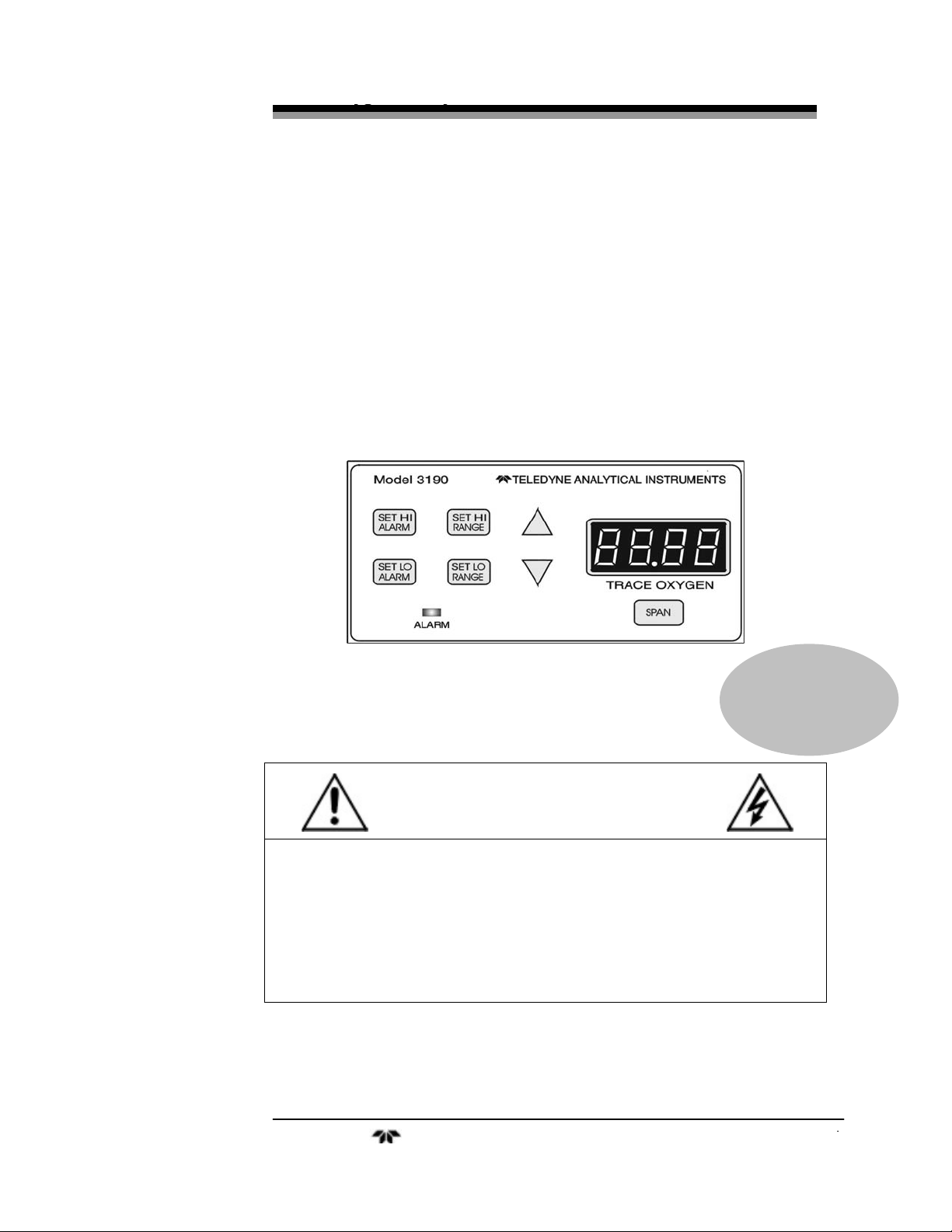
1.3 Front Panel Description
All controls and displays except the power switch are accessible
from the front panel. See Figure 1-1. The front panel has seven
pushbutton membrane switches, a digital meter, and an alarm indicator
LED for operating the analyzer. These features are described briefly
here and in greater detail in Chapter 4 - Operation.
Figure 1-1: Front Panel
Function Keys: Seven pushbutton membrane switches are used to select
the function performed by the analyzer:
• Set HI Alarm Set the concentration ABOVE which an
alarm activates.
• Set LO Alarm Set the concentration BELOW which
an alarm activates.
• Set HI Range Set the high analysis range for the
instrument (up to 0-1,000 ppm).
• Set LO Range Set the low analysis range for the
instrument (down to 0-1,000 ppm).
• Span Span-calibrate the analyzer.
Teledyne Analytical Instruments 2

Trace Oxygen Analyzer Introduction
Data Entry Keys: Two pushbutton membrane switches are used to
manually change measurement parameters of the instrument as they are
displayed on the LED meter readout:
Up Arrow Increment values of parameters upwards
as they are displayed on the LED readout.
• Down Arrow Increment values of parameters
downwards as they are displayed on the
LED readout.
Digital LED Readout: The digital display is a LED device that
produces large, bright, 7-segment numbers that are legible in any
lighting environment. It has two functions:
• Meter Readout
As the meter readout, it displays the
oxygen concentration currently being
measured.
• Measurement Parameters Readout
It also displays user-definable alarm set-
points, ranges, and span calibration point
when they are being checked or changed.
1.4 Rear Panel Description
The rear panel contains the electrical input and output connectors.
Separate rear panel illustrations are shown in Figure 1-2 for the AC and
DC powered versions of the instrument. The connectors are described
briefly here and in detail in the Chapter 3 - Installation.
Teledyne Analytical Instruments 3

Introduction Model 3190Z
Figure 1-2 Rear Panel (AC and DC versions)
Power Connection
AC version: 100–240 VAC, 50/60 Hz. The
connector housing includes the fuse
holder and the power switch.
DC version: Requires 10 - 36 VDC.
Fuse Holder: Replacing the fuse is described in
Chapter 5 - Maintenance.
Teledyne Analytical Instruments 4

Trace Oxygen Analyzer Introduction
I/O Power Switch: Turns the
instrument power ON (I) or OFF (O).
• Analog Outputs 0–10 VDC concentration output.
0–10 VDC Range ID (or optional
over-range) output.
4–20 mADC concentration output,
negative ground.
• Alarm
Connections HI Alarm, LO Alarm, and Sensor
Failure Alarm connections.
• RS-232 Port Serial digital output of concentration
and range signals.
• External Probe Connects to the remote probe or
remote analysis unit.
Teledyne Analytical Instruments 5

Introduction Model 3190Z
(This page intentionally left blank)
Teledyne Analytical Instruments 6

Trace Oxygen Analyzer Operational Theory
Operational Theory
2.1 Introduction
The analyzer is composed of three subsystems:
1. Analysis unit with zirconium oxide sensor(s)
2. Control unit with signal processing, display and controls
3. Interface unit, supplying signals between 1 and 2.
The analysis unit is designed to accept the sample gas and direct it
to the sensitive surface of the zirconium oxide sensor.
The control unit processes the sensor output and translates it into an
electrical concentration, which supplies the customer with range, alarm
outputs, and a meter readout giving the trace oxygen level. It contains a
microcontroller that manages all signal processing, input/output, and
display functions for the analyzer.
The interface unit receives power from the control unit, and creates
precision heater and bias voltages for the zirconium oxide sensor.
2.2 Zirconium Oxide Sensors
2.2.1 Principles of Operation
Teledyne’s zirconium oxide sensor is a miniature solid state
sensor. It uses a stabilized zirconia disc as an electrolyte with a sensing
electrode (the cathode) and a counter electrode (the anode) on each side
of the disc. The zirconia is heated to a temperature of about 500°C via a
built-in heater. By applying a suitable reference voltage across the
cathode and anode, the heated zirconia acts as an electrolyte which is
capable of moving oxygen ions within its crystalline structure. This
allows for the reduction of oxygen molecules reaching the cathode and
the generation of a current equivalent to the amount of oxygen in a
sample measured in parts per million (ppm).
Teledyne Analytical Instruments 7

Operational Theory Model 3190Z
The sensor is designed for long term stability with an operating
life of 5 years.
This unit features one or two sensors, and can be custom-designed
for a specific range of oxygen analysis.
2.2.2 The Effect of Pressure
In order to state the amount of oxygen present in the sample as a
specific portion of the gas mixture, it is necessary that the sample diffuse
into the sensors under constant pressure.
If the total pressure increases, the rate that oxygen reaches the
sensors will also increase. The electron transfer, and therefore the
external current, will increase, even though the proportion of oxygen has
not changed. It is therefore important that the sample pressure at the
sensors, (usually vent pressure) remain relatively constant between
calibrations.
2.3 Electronics
2.3.1 General
The signal processing uses a microcontroller with on-board RAM
and ROM to control all signal processing, input/output, and display
functions for the analyzer. System power is supplied from a universal
power supply module designed to be compatible with most international
power sources.
The power supply circuitry is on the Power Supply PCB, which is
mounted vertically, just behind the rear panel of the control unit.
The signal processing electronics, which includes the signal
amplifiers, microcontroller, analog to digital converter, and digital to
analog converter, are located on the Main PCB. It is mounted vertically
just behind the front panel of the control Unit.
Teledyne Analytical Instruments 8

Trace Oxygen Analyzer Operational Theory
2.3.2 Signal Processing
Figure 2-4 is a block diagram of the signal processing electronics
described below.
Figure 2-4: Block Diagram of the Signal Processing Electronics
In the presence of oxygen, the sensor(s) produce a current. A
current to voltage amplifier (I–E AMPL) converts this current to a
voltage.
The output from the I-E amplifier and subsequent buffer circuit (not
shown) is sent to an analog to digital converter (ADC), and the resulting
digital concentration signal is sent to the micro controller.
The digital concentration signal along with input from the front
panel buttons (KEYBOARD) is processed by the micro controller, and
appropriate output signals are directed to the display, alarm relays, and
Teledyne Analytical Instruments 9

Operational Theory Model 3190Z
RS-232 (optional) output. The same digital information is also sent to a
8-bit digital to analog converter (DAC) that produces the 0-10 VDC
analog concentration signal and the 0-10 VDC analog range ID output.
A current to voltage converter (E–I CONV) produces the 4-20 mADC
analog concentration signal.
Teledyne Analytical Instruments 10

Trace Oxygen Analyzer Installation
Installation
Installation of the analyzer includes:
1. Unpacking the system.
2. Mounting the control unit and external sample block.
3. Making the electrical connections.
4. Making the gas connections.
5. Testing the installation.
CAUTION: READ THIS CHAPTER IN ITS ENTIRETY BEFORE
INSTALLING THE UNITS.
THE MODEL 3190Z IS FOR INDOOR USE ONLY.
THE SAMPLE MUST BE FREE OF ENTRAINED
SOLIDS, WATER, OR COMBUSTIBLE COMPOUNDS.
3.1 Unpacking the Analyzer
As soon as you receive the instrument, carefully unpack and inspect
control unit, external probe, and any included accessories for damage.
Immediately report any damage to the shipping agent. The analyzer is
shipped with all materials needed to install and prepare the system for
operation.
Teledyne Analytical Instruments 11

Installation Model 3190Z
3.2 Location and Mounting
3.2.1 Control Unit Installation
The 3190Z control unit is designed to be panel-mounted in a
general purpose, indoor area, away from moisture and the elements. The
unit should be installed at viewing level in a sheltered area.
CAUTION: FOR THE DC POWERED VERSION, THE CONTROL
UNIT CHASSIS MUST BE ISOLATED FROM THE
INPUT POWER GROUND.
Refer to the Outline Diagram for the physical dimensions of the
analyzer, which can be found at the back of the manual.
3.2.2 External Probe Installation
The external probe should be installed as close as possible to the
control unit
The standard Model 3190Z includes the external probe unit
depicted in the Final Assembly and the Analysis Unit (probe) Outline.
Dimensions are also given in the Specifications section in the Appendix.
For special applications, the type of external probe unit supplied
may vary depending on the specific process. With these systems,
specific installation and interconnect information is given in a separate
probe manual or in an addendum to this manual depending on the model
External Probe used. The addendum will reference the specific Outline
and Interconnection Drawings in the Drawings section of this manual,
and provides any other appropriate information.
3.3 Electrical Connections
Figure 3-2 shows the two alternate Model 3190Z rear panels. The
first illustration shows the AC powered version, and the second
illustration shows the DC powered version. The only difference between
them is the power connections; all other connections are the same.
Primary Input Power (AC version): The power cord receptacle, fuse
block and power switch are located in the same assembly. A 6-foot
Teledyne Analytical Instruments 12

Trace Oxygen Analyzer Installation
standard AC power cord is supplied with the control unit. Insert the
female plug end of the power cord into the power cord receptacle.
The universal power supply allows direct connection to any 100240VAC, 50/60 Hz power source. The fuse block, to the right of the
power cord receptacle, accepts a 5 × 20 mm, 0.5A time-delay fuse (see
Fuse Replacement in Chapter 5 - Maintenance).
The power switch is located on the right-hand end of the power
source input receptacle assembly.
Primary Input Power (DC version): The 10–36 VDC power is
connected via the + and − terminals in the upper-left corner of the panel.
The fuse receptacle, to the right of the power terminal strip, holds a 0.5A
fast-acting fuse (see Fuse Replacement in Chapter 5 - Maintenance).
The Power switch is located below the fuse receptacle.
CAUTION: INSERT THE STRIPPED TIPS OF WIRES ENTIRELY
INTO THE TERMINAL BLOCKS. DO NOT LEAVE
EXPOSED WIRE OUTSIDE OF THE HOLES IN THE
BLOCKS.
CAUTION: THE CONTROL UNIT CHASSIS MUST BE ISOLATED
FROM THE GROUNDING SYSTEM OF THE DC INPUT
POWER.
Teledyne Analytical Instruments 13

Installation Model 3190Z
Figure 3-2 Rear Panel Electrical Connectors for AC and DC Units
Analog Outputs: There are three DC output signal connectors with
screw terminals on the panel. There are two wires per output with the
polarity noted. See Figure 3-3. The outputs are:
0–10 V Concentration: Voltage is proportional to oxygen reading, from
0 V at 0 ppm oxygen to 10 V at full scale ppm
oxygen. (Full scale = 100% of programmed
range).
0–10 V Range ID: 3.33 V = Low Range, 6.66 V = High Range
4–20 mA % Range: Current is proportional to oxygen reading, from 4
mA at 0 ppm oxygen to 20 mA at full scale ppm
oxygen. (Full scale = 100% of programmed
range).
Teledyne Analytical Instruments 14

Trace Oxygen Analyzer Installation
Alarm Relays: The three alarm circuit connectors are screw terminals
for making connections to internal alarm relay contacts. There is one set
of contacts for each type of alarm. Contacts are Form C, with normally
open and normally closed contact connections capable of switching up
to 0.5A at 125 VAC into a resistive load.
The alarm relay circuits are designed for failsafe operation,
meaning the relays are energized during normal operation. If power fails
the relays de-energize (alarms activated).
The contact connections are indicated diagrammatically on the rear
panel as normally closed (NC), common (C), and normally open (NO).
Figure 3-3 explains how these act in failsafe operation.
The specific descriptions for each type of alarm are as follows:
HI Alarm Configured as high alarm (actuates when
concentration is above threshold). Can be set
anywhere within the full range of the analyzer (11,000 ppm), but must be set ABOVE the threshold set
for the LO Alarm.
LO Alarm Configured as low alarm (actuates when
concentration is below threshold). within the full
range of the analyzer (1-1,000 ppm), but must be set
BELOW the threshold set for the HI Alarm.
Sensor Fail Not active in this product
Figure 3-3: Contact ID for FAILSAFE Relay Operation
Teledyne Analytical Instruments 15

Installation Model 3190Z
External Probe: The receptacle for the analysis unit cable is located in
the lower left-hand corner of the rear panel. The 6-pin Minifit ™
connector is keyed to fit only one way into the receptacle; do not force
it. The other end of the cable consists of four separate wires. These
should be connected to the terminal strip on the analysis unit as follows:
Red: #1 White: #3
Black: #2 Green: #4
Refer to the Final Assembly, located at the back of the manual.
3.4 Gas Connections
Gas connection instructions depend on the specific external probe
used and any special requirements of the process being monitored.
The standard Model 3190Z External Probe has inlet and outlet
fixtures only. Calibration gases must be externally piped into the sample
inlet through appropriate valves. Quarter-inch tube fittings are used. For
metric installations, quarter-inch to 6 mm adapters can be supplied.
In general, sample flow and pressure must not create significant
backpressure past the sensor. For the standard probe, 2 SCFH (1 LPM)
is the nominal recommended flow rate.
The pressure required will depend on the sampling system. The
simplest method of pressure regulation is venting the outlet directly to
atmosphere. If venting into a system of varying pressure, some form of
pressure regulation is required.
3.5 Installation Checklist
Before connecting the instrument to a power source and applying
power, make sure you have:
• Correctly installed the sample and exhaust gas lines
• Checked for leaks
• Set the sample pressure to 5-10 psig nominal
Once the above checks have been made, you can apply power. The
instrument is now ready for operation.
Teledyne Analytical Instruments 16

Trace Oxygen Analyzer Operation
Operation
4.1 Introduction
Once the analyzer has been mounted, the gas lines connected, and
the electrical connections made, the analyzer can be configured for your
application. This involves setting the system parameters as follows:
• Defining the user-selectable analysis ranges
• Setting alarm set-points.
• Calibrating the instrument
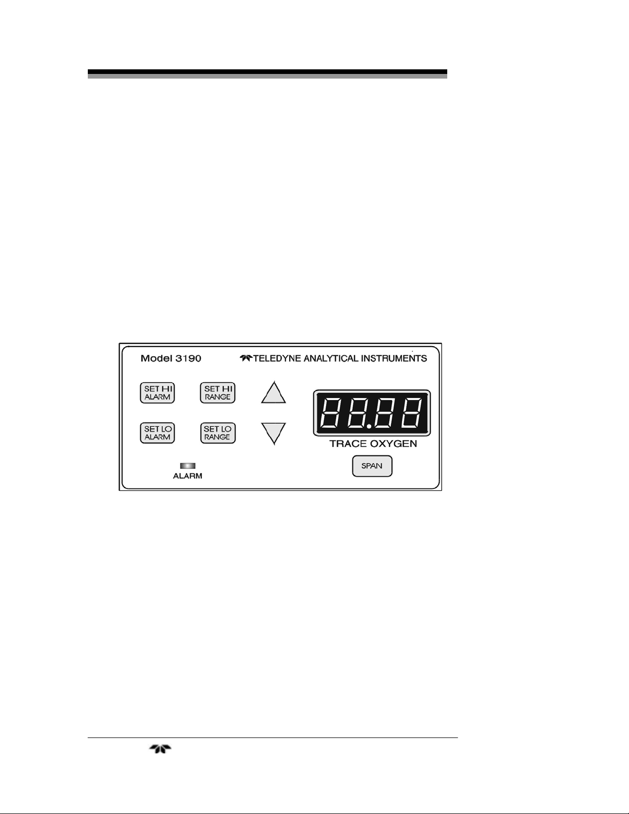
All of these functions are performed via the front panel controls,
shown in Figure 4-1.
Analyzing a gas sample for the percent oxygen level through the
cell block is the default mode of operation. The analyzer is monitoring
the oxygen level as long as no front panel buttons have been pressed.
Figure 4-1: Front Panel Controls and Indicators
Teledyne Analytical Instruments 17

Operation Model 3190Z
4.2 Using the Function and Data Entry Buttons
When one of the function buttons is being pressed, the analyzer is
in the Setup mode or the Calibration mode.
The four setup function buttons on the analyzer are:
• SET HI ALARM
• SET LO ALARM
• SET HI RANGE
• SET LO RANGE
The Calibration mode button is:
• SPAN
The data entry buttons (Δ and ∇) adjust the value displayed on the
TRACE OXYGEN meter while one of the function buttons is being held
down.
• Δ : Increments the displayed value upwards.
• ∇ : Increments the displayed value downwards.
Any of the functions can be selected at any time by pressing the
appropriate button.
Each function will be described in the following sections. Although
the operator can use any function at any time, the order chosen in this
manual is appropriate for an initial setup.
4.3 Setting the Analysis Ranges
The two user-definable analysis ranges are both capable of being
adjusted from 0-10 ppm to 0-1,000 ppm oxygen concentration.
The analyzer automatically switches from the LO range to the
HI range when the oxygen concentration reaches the LO range fullscale value. It will switch back to the LO range when the oxygen
concentration falls below the LO range full-scale value
Note: The HI Range set-point MUST be set at a higher
concentration than the LO Range set-point.
Teledyne Analytical Instruments 18

Trace Oxygen Analyzer Operation
4.3.1 HI Range
Setting the HI Range full-scale value defines the LEAST sensitive
analysis range to be used. To set the HI Range:
1. Press the SET HI RANGE function button once.
2. Immediately (within 5 seconds) press either the Δ or ∇ button
to raise or lower the displayed value as required, until the
display reads the desired full-scale concentration.
4.3.2 LO Range
Setting the LO Range full-scale value defines the MOST sensitive
range to be used. To set the LO Range:
1. Press the SET LO RANGE function button once.
2. Immediately (within 5 seconds) press either the Δ or ∇ button
to raise or lower the displayed value as required, until the
display reads the desired full-scale concentration.
4.4 Setting the Alarm Setpoints
The alarm set-points can be adjusted over the full range of the
analyzer (0-1,000 ppm oxygen content). The set-point values are
expressed in ppm only.
Note: The HI Alarm set-point MUST be set at a higher
concentration than the LO Alarm set-point.
4.4.1 HI Alarm
Setting the HI Alarm sets the value ABOVE which the HI Alarm
will activate. To Set the HI Alarm:
1. Press the SET HI ALARM function button once.
2. Within 5 seconds press either the Δ or ∇ button to raise or lower
the displayed value as required, until the display reads the
desired concentration.
4.4.2 LO Alarm
Setting the LO Alarm sets the value BELOW which the LO alarm
will activate. To set the LO Alarm:
Teledyne Analytical Instruments 19

Operation Model 3190Z
1. Press the SET LO ALARM function button once.
2. Within 5 seconds press either the Δ or ∇ button to raise or lower
the displayed value as required, until the display reads the
desired concentration.
4.4.3 Sensor Fail Alarm
Not active in this product.
4.5 Selecting a Fixed Range or Autoranging
The Model 3290 can operate in fixed high, fixed low, or auto-
ranging mode. To change modes:
1. Press and then release the SET HI RANGE and the SET LO
RANGE buttons simultaneously.
2. Within 5 seconds press either the Δ or ∇ button until Auto, Lo,
or Hi displays on the LCD, as desired.
After about three seconds, the analyzer resumes monitoring in the
selected range mode.
4.6 Calibration
Power up the analyzer and allow the LED reading to stabilize. Wait at
least ten minutes after powering, giving the heater and bias voltages
enough time to reach operating voltage. Set the alarm set-points and the
full-scale ranges to the desired values.
Procedure:
1. Apply calibration gas of a known concentration. A span gas
containing an oxygen content of 60-100% of the range of the
analyzer is recommended.
Note: If the analyzer output goes above the high alarm set-point
or below the low alarm set-point, the front panel ALARM
Indicator located beneath the SET function buttons will blink.
When the SPAN key is pressed, the alarm indicator will stop
blinking.
2. Press the SPAN button once.
Teledyne Analytical Instruments 20

Trace Oxygen Analyzer Operation
3. Immediately (within 5 seconds) press either the Δ or ∇ button
until the display is stable and displays the oxygen concentration
of the applied calibration gas. Once set, the unit will enter
Analyze Mode after approximately three seconds.
The unit is now calibrated.
If the output of the sensor is outside of the expected range, this may be
caused by:
a) Bad electrical connection between the control and
analysis unit
b) Improperly analyzed or entered calibration gas value
c) Electronics failure
The unit will not accept the attempted calibration and will flash
‘0000’ on the LED display unit a valid calibration is performed.
4.7 LED Display on StartUp
When the unit is powered, it will initially display “8.8.8.8” for a
short period of time. This is to confirm all LED segments are
functioning. Afterward, the LED display will initiate a delay countdown,
allowing the sensor’s heater to begin charging and capture a zero
reading. Flowing “zero” gas or a sensor is not needed for this
instrument adjustment.
Teledyne Analytical Instruments 21

Operation Model 3190Z
(This page intentionally left blank)
Teledyne Analytical Instruments 22

Trace Oxygen Analyzer Maintenance
Maintenance
Aside from normal cleaning and checking for leaks at the gas
connections, the Model 3190Z should not require any maintenance
beyond replacement of zirconium oxide sensors, and perhaps a blown
fuse. Routine maintenance includes occasional recalibration, as
described in Chapter 4 - Operation.
5.1 Replacing the Fuse
5.1.1 AC Powered Units
When a fuse blows, check first to determine the cause, then replace
the fuse using the following procedure:
1. Disconnect the AC power and place the power switch located on
the rear panel in the O position. Remove the power cord from the
receptacle.
2. The fuse receptacle is located in the power cord receptacle
assembly in the upper left-hand corner of the rear panel. See
Figure 5-1.
Figure 5-1: AC Fuse Replacement
Teledyne Analytical Instruments 23

Maintenance Model 3190Z
3. Insert a small flat-blade screwdriver into the slot in the receptacle
wall nearest the fuse and gently pry open the fuse receptacle. The
fuse holder will slide out. The fuse in use is visible in the clip.
To open the spare fuse compartment, push on one end until it
slides out.
4. Remove the bad fuse and replace it with a 5×20 mm 0.5 A,
250 VAC, IEC, time lag (T) fuse (P/N F1128) for AC units.
5. Replace the fuse holder into its receptacle, pushing in firmly
until it clicks.
5.1.2 DC Powered Units
In units with DC power, the fuse is located on the rear panel above
the ON/OFF switch.
1. Open the fuse holder by unscrewing and removing the cap
marked FUSE.
2. The fuse is located inside the receptacle, not inside the cap. Both
terminals are on the same end of the fuse. Pull straight out
without twisting to remove the old fuse from the receptacle, and
replace it with a 0.5 A, 125 VDC, very quick acting (FF)
Microfuse (P/N F51).
3. Replace the cap by screwing it back into the receptacle.
5.2 Sensor Installation or Replacement
5.2.1 When to Replace a Sensor
The sensors used in this product will typically last five years or
longer in service. Typically, the sensors will fail either high or
low. Inaccurate or erratic readings are a sign that one of the
sensors may have failed. In most cases, we recommend the
entire unit be returned to an authorized Teledyne Service Center
for sensor replacement.
Teledyne Analytical Instruments 24

Trace Oxygen Analyzer Appendix
Appendix
A.1 Specifications
Ranges: Two user selectable ranges can be set
between 0-10 ppm and 0-1,000 ppm
oxygen. Default ranges are 0-100 ppm and
0-1,000 ppm oxygen
Signal Output: Voltage: 0–10 VDC, negative ground
Current: 4-20 mA, negative ground
Range ID: 0-10 VDC
Display: Light-emitting diode (LED) display
Alarms: One high alarm relay, adjustable; one low
alarm relay, adjustable; one sensor failure
relay. All alarms failsafe.
System Operating Temp: 0 - 50°C
Accuracy: ±2% of full scale at constant temperature
±5% of full scale over 0-50°C range once
temperature equilibrium is reached (at 3%
and 5% user defined ranges).
Response Time: 90% in less than 20 seconds at 25°C
System Power: AC (100-240 VAC, 47/440 Hz), or DC
Requirements: (10-36 VDC); user specified
System Enclosure: Panel Mount: 2.81" H × 6.0" W × 2.87" D
(71.4 mm × 152.4 mm × 72.9 mm).
Face Plate: 3.75" H × 7.0" W (95.3 mm H ×
177.8 mm W). Faceplate rated to NEMA-4
Sensor Type: Zirconium Oxide
Analysis Unit: 4.0" H × 6.0" W × 3.25" D
(101.6 mm × 152.4 mm × 82.6 mm)
Teledyne Analytical Instruments 25

Appendix Model 3190Z
A.2 Spare Parts List
1* C-64586A PC Board, Power Supply (AC-version)
1* C-64586B PC Board, Power Supply (DC-version)
1 C-76491C PCB Board, Main
1 C-76490C Interface Unit
2* F-1130 Fuse (AC), ½A, 250 VAC
IEC Type T, 5x20mm
1* F-51 Fuse (DC), ½A, 125 VDC Micro-fuse
1 S-1439 Sensor, 0-1,000 ppm, zirconium oxide
* - configuration-dependent
A minimum charge of US $150.00 is applicable to spare parts orders.
IMPORTANT: Orders for replacement parts should include the
part number and the model and serial number of the
system for which the parts are intended.
Send orders to:
TELEDYNE ELECTRONIC TECHNOLOGIES
Analytical Instruments
16830 Chestnut Street
City of Industry, CA 91749-1580
Telephone: (626) 961-9221
TWX: (910) 584-1887 TDYANYL COID
Fax: (626) 961-2538
…or your local representative.
Teledyne Analytical Instruments 26

Trace Oxygen Analyzer Appendix
A.3 Drawing List
D-76533 Outline/Interconnection Diagram
A.4 Miscellaneous
The symbol: ~ is used on the rear panel of the model 3190Z to
signify volts alternating current (VAC).
Teledyne Analytical Instruments 27
 Loading...