

Page 1

INSTRUCTION MANUAL
FOR
TRACE OXYGEN ANALYZER
MODEL 311-D
RANGES: 0-100 PPM; 0-1000 PPM; 1% AND 100%
TELEDYNE ANALYTICAL INSTRUMENTS
16830 CHESTNUT STREET
CITY OF INDUSTRY, CALIF. 91749
TELEPHONE: (626) 934-1500
FAX: (626) 961-2538
TWX: (910) 584-1887 TDYANYL COID
EASYLINK: 628-31862
Web: www.teledyne-ai.com
Page 2

TABLE OF CONTENTS
MODEL 311D
1. INTRODUCTION 1
1.1 Description 1
1.2 Method of Analysis 1
1.3 Outstanding Features 1
1.3.1 Micro-Fuel Cell 1
1.3.2 Reliable Calibration 1
1.3.3 Integral Power Supply 2
1.3.4 Accuracy and Response 2
1.3.5 Compact Packaging 3
1.3.6 Circuit Description 3
2. SUPPORTING EQUIPMENT AND SERVICES 4
2.1 Sampling Equipment 4
2.2 Power Service 4
3. OPERATION 4
3.1 Introduction 4
3.2 Calibration 5
3.2.1 Calibration Procedure 5
3.3 Positive Pressure Sampling 6
3.4 Atmospheric Pressure Sampling 6
4. MAINTENANCE 7
4.1 Battery Power Supply Services 7
4.2 Routine Maintenance 7
4.3 Cell Replacement 7
4.4 Cell Warranty 8
5. TRANSDUCTION AND TEMPERATURE COMPENSATION 9
6. LEAK TESTING 9
SPECIFICATION DATA 10
APPENDIX - Effect of CO
on B-2C Cell Life 11
2
SPARE PARTS LIST 12
DRAWING LIST 13
Page 3

1. INTRODUCTION
1.1 Description
portable trace oxygen analyzer which can be operated without an external power source, and
reliably calibrated without the use of cumbersome, questionable, “certified” calibration gases.
The instrument provides for trace oxygen analysis in decade steps ranging from 0-100 to 0-1000
ppm (full scale) plus a 0-1% and 0-100% calibration range that encompasses the known oxygen
concentration of atmospheric air (20.9%, or 209,000 ppm).
Sample oxygen is read from an extremely accurate digital panel meter (0.1% accuracy) whose
range of measurement is determined by the position of the range selector switch.
Sample gas is introduced and vented via a pair of swagelok quick-disconnect fittings that feature
integral shutoff valves that automatically close when the mating male fitting is withdrawn. The
fittings are an integral part of the measuring cell manifold, so that internal sample passage
volume is at an absolute minimum. Sample flow control, although not critical (0.1 to 10
liters/min.), must be accomplished with accessory equipment.
1.2 Method of Analysis
electrochemical transducer, which functions as a fuel cell; in this instance, the fuel is oxygen.
Oxygen diffusing into the cell reacts chemically to produce an electrical current that is
proportional to the oxygen concentration in the gas space immediately adjacent to the transducer
sensing surface. A two-stage solid state amplifier that features operational amplifiers whose
power consumption per unit is less than (5) milliwatts amplifies the linear, but minute, signal
produced by the transducer from trace oxygen. The dual stages of amplification provide enough
gain to read on the digital panel meter and use a thermistor- controlled network to compensate
for the positive temperature coefficient of the transducer.
1.3 Outstanding Features
Model 311-D:
1.3.1 Micro-Fuel Cell
transducer with no electrolyte to change or electrodes to clean. When the cell reaches the end of
its useful life, it is merely thrown away and replaced, as one would replace a worn-out battery in
a flashlight. The life of the cell is warranted by TAI (see Section 4.4) in a fashion similar to that
employed by the manufacturers of automobile batteries. This procedure guarantees the customer
compensation for failure of a given cell to perform as specified.
1.3.2 Reliable Calibration
the user to calibrate the instrument with the most economical, reliable
gas there is -- atmospheric air.
The special “CAL” range of the instrument is meant for calibrating the span in ambient air to
20.9% oxygen. By drawing air through the instrument (see the sample calibration procedure in
Section 3.2) reliable calibration can be achieved.
: The Teledyne Analytical Instruments (TAI) Model 311-D is a
: The sample oxygen is measured by a unique
: The following unique features are incorporated into the
: The Micro-Fuel Cell is a sealed electrochemical
: The unique qualities of the Micro-Fuel Cell allow
, abundant, standardization
-1-
Page 4

After the electronics have been properly zeroed (a one-time factory operation), the instrument
cannot produce an output indication in the absence of oxygen; therefore, the need for a “zero”
standardization gas is obviated.
1.3.3 Integral Power Supply
(DPM) requirements of the instrument amplifier are furnished by three internally-mounted 750
milliampere-hour nickel-cadmium batteries. Fully charged, these batteries will provide enough
power to operate the instrument continuously
overnight charge on a 2-day duty cycle should keep the original batteries usable for many years.
A “LOW BATTERY” indication is shown on the digital display.
An integral charging circuit and a detachable power cord are provided so that the batteries may
be recharged from any 50 or 60 cycle, 105 to 125 volt convenience outlets.
The instrument is designed to either sample or have its batteries recharged. Both operations
cannot be carried out simultaneously. TAI has deliberately interlocked the circuitry in this way.
Only when the selector switch is placed in the “OFF” position will the neon lamp on the back
plate of the 311D light up to indicate power to the battery charging circuit.
A current limiting resistor (53.2 ohms) is potted into the end of each battery. This assures that,
under no circumstances, can more than 80 milliamperes be switched or drawn from either battery
supply.
BATTERY CHECK
selector knob counter-clockwise to the battery test position and hold there; the switch is springloaded, and must be held. The meter should read more than 1600; otherwise, the batteries need
to be recharged. Release the Range Selector Switch, and it will automatically return to the
“OFF” position. When the batteries are set at a really low charge condition, the “LOW BATT”
warning is displayed. Caution should be taken not to discharge the batteries any further.
1.3.4 Accuracy and Response
of ±0.2% of full scale, or ±0.2 ppm, whichever is greater, at constant temperature. A ±5% of
reading accuracy is achievable throughout the operating temperature range of 30 to 125°F.
With a sample flowrate of 150 cc/min., 90% response is achieved in 10 seconds in all the
positions.
1.3.5 Compact Packaging
inch aluminum case that is equipped with a carrying handle and foot pads.
Access to the instrument interior is gained by loosening (ccw) the three 1/4” slot-head fasteners
on the back of the outer case. The case may then be detached from the control panel assembly.
: To determine the state of the rechargeable batteries, turn the range
: The differential power and digital panel meter
for a period of ca. 500 hours. Furthermore, an
: The Model 311D provides monitoring accuracy
-2-
: The instrument is housed in a 6-1/8 x 9-1/2 x 5-5/8
Page 5

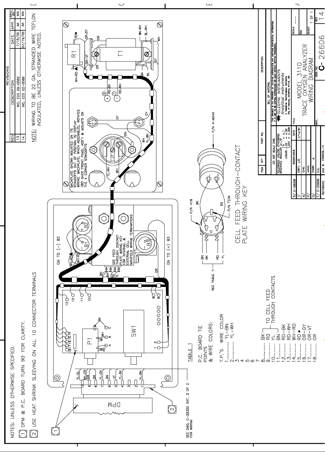
Further disassembly may be accomplished by removing the backplate assembly from its four
mounting standoffs, and laying the two separated assemblies out as illustrated on the “Analyzer
Wiring Diagram”. The diagram is included among the drawings at the rear of the manual.
1.3.6 Circuit Description
transducer; its output current is in proportion to the concentration of the oxygen measured. A
current-to-voltage converter, A3, supplies an output voltage, whose level is set by the range
switch to the span pot. A thermistor varies the gain of amplifier A2 as the temperature of the
cellblock changes; this compensates for the change in output of the Micro-Fuel Cell due to
changes in temperature. The output of A2 is shown on the digital panel meter (DPM). Refer to
the schematic diagram.
The batteries are charged when the instrument is connected to the main power supply, and kept
in the off position. The batteries are charged at 80 mAmp, set by resistor R1. In the
measurement mode, amplifier A1b, which floats the ground at the center of the power supply,
controls the power supplied to the amplifier and the DPM.
The synthetic ground amplifier maintains a constant ratio of 1:1 between the negative and
positive power supplies. The constant ratio keeps the offset voltage of the amplifier from
changing as the battery voltage varies up and down. This prevents damage to the Micro-Fuel
Cell, due to oxidation caused by reverse-polarity charging. The synthetic ground is produced by
connecting the non-inverting input of amplifier A1b to the junction of R7 and R8 (which is at the
ground potential); the output of A1b is the synthetic ground. The resulting dual power supplies
have a constant ratio of:
Neg. supply/Pos. supply = R7/R8 = 1.
WARNING
cells may be damaged, and this will shorten the life of the battery. Always check the battery
charge before using the instrument.
If the battery voltage should drop to zero while the unit is operating, the FET switch Q1 shorts
the Micro-Fuel Cell; this protects the cell from damage or saturating with oxygen.
2. SUPPORTING EQUIPMENT AND SERVICES
2.1 Sampling Equipment
pressure and flowrate of the sample gas. For positive pressure applications, TAI suggests a
simple throttle valve, installed in the sample line between the sample point and the analyzer.
The flowrate should be limited to 0.1 to 10 liters/min. IMPORTANT: If a pressure regulator is
: Caution should be exercised! If the battery is discharged excessively, the battery
: A Micro-Fuel Cell (Class B-2C) is used as the
-3-
: The customer must provide a means of controlling the
Page 6

necessary or desirable, it must have a metallic diaphragm. Regulators with organic or plastic
diaphragms are permeable to oxygen, and if used in the sampling system, will lead to high
oxygen readings.
For atmospheric pressure sampling, connect a pump and flow control valve downstream
analyzer and draw (rather than push) the sample through the instrument.
TAI supplies three male disconnect fittings with the instrument; one for installation of the
customer’s sample line, one to be used to open the vent fitting of the instrument, and one
(equipped with a plastic tube) for drawing air through the unit for calibration purposes.
2.2 Power Service
capable of delivering a maximum of 1/4 ampere of current will be periodically
recharge the instrument’s battery power supply. An eight-foot, UL approved, 3-wire, detachable
power cord is provided with the instrument and should be stored in a safe place when not in use.
As a no-cost option, the 311D can be furnished with 220-volt, 50 or 60 Hertz charging power.
3. OPERATION
3.1 Introduction
instant use. The Micro-Fuel Cell is in place within the manifold, and prior to shipment the
manifold was purged with an inert gas to eliminate all but traces of oxygen from the internal
sampling system. The integral shutoff valves in the quick-disconnect sample fittings, if not
disturbed, will maintain this inert atmosphere within the manifold indefinitely. This can be
demonstrated by advancing the range selector switch to the 0-1000 ppm position.
When the range selector is advanced from the “OFF” position, power to the instrument’s
circuitry is established. The meter will instantly respond to the residual oxygen within the
integral sample passages.
It is impossible to achieve a “perfect” seal of the internal sample system, and what the meter is
indicating is the diffusion/consumption balance point of the internal sample system and the
micro-fuel cell.
This “balance” point, with a properly calibrated instrument, is always within the limits of the 100
ppm range. If the reading claims off the limits of this scale, a leak in the manifold assembly is
indicated.
TO EXTEND THE CELL LIFE AND MINIMIZE THE TIME REQUIRED TO MAKE
THE NEXT ANALYSIS, THE INSTRUMENT SHOULD ALWAYS BE PURGED WITH
THE SAMPLE OR AN INERT GAS PRIOR TO BEING TAKEN OUT OF SERVICE
FOR STANDBY OR STORAGE.
3.2 Calibration
cludes a definitive calibration cycle. TAI feels that the interval between calibrations should be
: A source of single-phase, 105 to 125 volt, 50 or 60 Hertz power,
: The Model 311D is delivered completely assembled and ready for
-4-
: The inherently constant output of the cell during its useful life pre-
from the
required to
Page 7

dictated by the customer’s application. If the instrument were being used to certify the oxygen
content of a product for delivery, then a calibration prior to certification would certainly be in
order. If, on the other hand, the instrument is being used to monitor or guard a sample, the
evidence provided by the analyzer will determine when a calibration check is in order.
DO NOT CALIBRATE THE INSTRUMENT UNLESS THERE IS A TRACE OXYGEN
GAS READILY AVAILABLE FOR PURGING IMMEDIATELY FOLLOWING THE
CALIBRATION PROCEDURE. (The longer the instrument is exposed to high concentrations
of oxygen, the longer it takes to get back to its working ppm range.)
3.2.1 Calibration Procedure
calibrate the instrument:
1. Stand the instrument upright on a level surface, with the range switch
in the “OFF” position.
2. Advance the range switch to the “CAL” position.
3. Install the plastic-tube-equipped male disconnect fitting in either
of the analyzer’s sample ports, and a blank disconnect fitting in the
other port (direction of sample flow is of no importance). A pump
is recommended on the plastic tube. Pump the tube until the meter
reading is stable.
CAUTION
POSSIBILITY THE MICRO-FUEL CELL MAY LEAK. THE CELL CONTAINS KOH
SOLUTION WHICH IS CAUSTIC AND EXTREMELY HAZARDOUS! (See Appendix -
Material Safety Data Sheet).
4. Unlock and adjust the span control until the meter reads 20.9% oxygen.
BE SURE TO RELOCK THE CONTROL AFTER THE ADJUST MENT IS MADE.
5. Immediately after Step 4 has been accomplished, disconnect the
tubing equipped calibration fitting, and plug in either the sample or a source
of inert gas.
If the instrument is to be used for sampling after the calibration procedure has been complete,
follow the decreasing oxygen reading by positioning the range switch so that the meter gives the
best possible resolution of the oxygen. DO NOT ATTEMPT TO ACTUALLY TAKE A READING
UNTIL THE METER INDICATION STABILIZES. If the sample oxygen content lies within the
limits of 0-100 ppm, an overnight purge is recommended for the instrument to recover
sufficiently from the effects of the 209,000 ppm oxygen concentration of air (over four decades
of range differential). Recovery time is proportionally less for coarser ranges.
: DO NOT SUCK ON THE TUBE WITH YOUR MOUTH, THERE IS A
: Employ the following step-by-step procedure to
-5-
Page 8

If, on the other hand, the instrument is not to be used immediately after calibration, and a low
ppm oxygen gas is being employed as a purge, allow the manifold to be purged overnight, and
then disconnect both male fittings. ALWAYS DISCONNECT THE SOURCE FITTING FIRST,
AND IMMEDIATELY THEREAFTER, THE VENT FITTING.
3.3 Positive Pressure Sampling
pressure sample source, ALWAYS
1. Before making ANY connections to the instrument, establish a sample line
flow rate of 0.1 to 10 liters/min. Allow the sample to vent to atmosphere
long enough to purge the line free of air.
2. Install the vent fitting first
to make the connections in rapid order, so that atmospheric diffusion time
Through the vent fitting is held to a minimum.
When disconnecting the instrument, reverse the procedure: source fitting first
fitting.
The objective of the connect-disconnect procedure is to obviate the possibility of pressurizing
the manifold. IF A FLOWING SAMPLE WAS CONNECTED TO THE MANIFOLD
WITHOUT THE VENT FITTING IN PLACE, THE PRESSURE IN THE MANIFOLD
WOULD RISE AND BE EQUAL TO THE SAMPLE PRESSURE ALMOST
IMMEDIATELY. In such a situation, depending on the magnitude of the sample pressure,
leaks in the manifold might result.
3.4 Atmospheric Pressure Sampling
slightly
of the pump should also be equipped with a throttle valve, so that sample flow can be reduced to
0.1 - 10 liters/min. If pump loading is a consideration, the inlet side of the pump will have to
include a bypass path that is open to the atmosphere through still another throttle valve. The
sample path and bypass path may then be balanced by manipulating the two valves, so that
sample flow is within the prescribed limits without loading the pump.
UNDER NO CIRCUMSTANCES SHOULD THERE BY ANY RESTRICTIONS IN THE
LINE BETWEEN THE SAMPLE POINT AND THE ANALYZER -- partial-pressure-
sensitive device, any oxygen readings taken under these conditions would be erroneous, and
vacuums in excess of 1/3 atmosphere may damage the cell.
4. MAINTENANCE
4.1 Battery Power Supply Service
not connected to the AC power line. TAI suggests that an overnight recharge be accomplished
negative), a sample pump will be required downstream from the analyzer. The inlet side
proceed as follows:
: When connecting the instrument to a positive
and then the sample source fitting. Be prepared
, and then vent
: If the sample is at atmospheric pressure (or
-6-
. The Model 311D is for use ONLY when it is
Page 9

every two (2) days of continuous use. To recharge the batteries, place the range switch in the
“OFF” position and connect the power cord to a convenience outlet. The integral charging
circuit will automatically energize and regulate battery charging current when the switch is in the
“OFF” position and the AC cord is plugged into the power line. Under no circumstances allow
the instrument to remain “ON” when the “LOW BATT” warning is indicated. Charging the
batteries more than this will not
so.
WARNING
TO THE OPERATING POSITION WHILE THE UNIT IS PLUGGED INTO THE
POWER LINE! DOING SO MAY CAUSE THE INTEGRATED CIRCUITS TO FAIL.
When charging is completed, unplug the unit from the AC outlet. Turn the range switch to the
“BATT. TEST” position or to the operating position. NOTE: The “BATT. TEST” position will
not give a reliable indication of the battery charge immediately after a charge cycle. Allow the
unit to run for awhile before testing the batteries.
If the instrument is stored with the range switch in the “OFF” position (charge cord
disconnected), the period of time between charge periods should be one month. However, do not
leave it longer than the one-month period.
4.2 Routine Maintenance
routine maintenance is required, as there are no moving parts in the instrument. The Micro-Fuel
Cell is a sealed, modular component that should be replaced when faulty.
4.3 Cell Replacement
those of a mercury battery, in that both provide an almost constant output through their useful
life, and then fall off sharply towards zero at the end. If the sample being analyzed has a low (0100 ppm) oxygen concentration, cell failure will probably be indicated by the inability to
properly calibrate the analyzer. The user will find that very little adjustment of the 10-turn span
potentiometer will be required to keep the analyzer calibrated properly during the duration of a
given cell’s useful life. If large, many-turn adjustments (cw) are required to calibrate the
instrument, or calibration cannot be achieved within the range of the control, the cell should be
immediately replaced. (Read Section 4.4 before replacing the cell.)
To offset the possibility of not having a replacement cell available when it is needed, TAI
recommends that a spare cell be purchased shortly after the instrument is placed in service, and
each time the cell is replaced thereafter.
The spare cell should be carefully stored in an area that is not subject to large variations in
ambient temperature (75° F, nominal), and in such a way as to obviate any possibility of
incurring damage. Under no circumstances, disturb the integrity of the cell package until the
cell is to be actually used. If the cell package is punctured and air permitted to enter, the cell
will immediately start to react to the presence of oxygen.
: DO NOT TURN THE RANGE SWITCH EITHER TO “BATT. TEST” OR
damage them; allowing them to discharge completely may do
: Beyond adhering to a battery recharge schedule, no
: The characteristics of the Micro-Fuel Cell are similar to
-7-
Page 10

No tools are required to replace the cell in the instrument. Simply unscrew (ccw) the plug at the
bottom of the analyzer, and the cell will drop out of the manifold cavity.
Remove the new cell from its package, and carefully remove the shorting clip. Do not touch the
silver-colored sensing surface of the cell -- as it is covered with a delicate Teflon membrane that
can be ruptured in handling.
Place the cell on the end of the manifold plug, so that the sensing surface of the cell is in contact
with the plug, and the electrical contact plate end of the cell is facing upwards. Insert the cell
and plug into the manifold cavity, and screw the plug back into place. Apply as much pressure
as you can with your fingers, but use no tools.
After the cell has been installed, purge the instrument with an inert gas (or the sample), and then
proceed as directed in Section 3.2.1.
4.4 Cell Warranty
. The Class B-2C cell employed in the Model 311D is warranted
for 80,000 percent-hours or six (6) months of service (whichever occurs first).
With regard to spare cells, service time starts when the cell is removed from its shipping
package. The customer should stock only one spare cell per instrument at a time. Do not
attempt to stockpile spare cells.
The Model 311D should not be used in applications where CO
is a major component in the
2
sample. Concentrations of 1,000 ppm or less will not effect the cell performance. See Appendix
- “Effect of CO
on B-2C Cell Life.”
2
If a cell was working satisfactorily, but ceases to function before the warranty period expires, the
customer will receive credit, toward the purchase of a new cell.
Customer having warranty claims must return the cell in question to the factory for evaluation,
after obtaining an RMA number. If it is determined that failure is due to faulty workmanship or
material, the cell will be replaced at no cost to the customer.
-8-
WARNING
: Evidence of damage due to tampering or mishandling will render the cell
warranty null and void.
5. TRANSDUCTION AND TEMPERATURE COMPENSATION
The Micro-Fuel Cell has an inherent positive temperature coefficient, the effects of
which have been minimized through the implementation of a calibrated thermistor compensation
circuit.
Internal electronic calibration is accomplished by TAI. However, should there by any doubt
concerning it, the following procedure can be used to recalibrate. Refer to schematic.
Page 11

1. Disconnect cell.
2. Move range switch to “CAL” position.
3. Adjust P1 such that the output of A3, pin 6, measures between 0 and +0.5 mV, ideally
+-.3 mV.
4. Adjust P2 for 0 ± 1 mV at output of A2, pin 6.
5. Verify that the offset is the same on all ranges.
6. Re-connect cell.
6. LEAK TESTING
If a leak is suspected in the unit, DO NOT ATTEMPT TO TIGHTEN THE
DISCONNECT FITTINGS. THE FITTINGS ARE POTTED IN EPOXY AND
TIGHTENING THEM WILL BREAK THE SEAL! To check for leaks, TAI recommends
one of the following procedures:
Procedure 1:
1. Purge the instrument down as low as possible.
2. Place the vent line in water and disconnect the sample.
3. Next, disconnect the vent line and place the range switch on the X100 range.
4. The unit should stay on the X100 range if there are no leaks.
Procedure 2:
1. Purge the instrument with Nitrogen at the sample port.
2. Note the reading once it has stabilized (at least 24 hours on the 0-10 ppm range) and
increase the flow rate.
3. If the reading goes down, the unit, or the tubing to the unit, has a leak.
-9-
SPECIFICATION DATA
TAI SALES ORDER NUMBER
INSTRUMENT MODEL NUMBER 311D
INSTRUMENT SERIAL NUMBER
MICRO-FUEL CELL CLASS B-2C
ACCURACY: ±0.2% OF SCALE, OR ±1 PPM, WHICHEVER IS GREATER, AT
A CONSTANT TEMPERATURE; ±5% OF READING, OR ±1 PPM, WHICHEVER
IS GREATER, OVER THE OPERATING TEMPERATURE RANGE.
Page 12

OPERATING TEMPERATURE RANGE: 30° TO 125°F.
RESPONSE AND RECOVERY: AT THE SPECIFIED FLOWRATE (0.25 SCFH),
THE SENSOR OUTPUT SHOULD BE, IN TEN SECONDS, WITHIN ±10% OF AN
INTRODUCED GAS HAVING A CONCENTRATION OF 100 PPM OR MORE; FOR
A CONCENTRATION OF LESS THAN 100 PPM, THE SENSOR OUTPUT SHOULD
BE WITHIN ±10% IN SIXTY SECONDS (PROVIDED THAT THE SENSOR IS NOT
ALREADY SUPERSATURATED WITH A VERY HIGHLY-CONCENTRATED GAS,
AND THE INTRODUCED GAS IS NOT VERY LOW IN CONCENTRATION.
RANGES OF ANALYSIS: 0-100 PPM OXYGEN
0-1000 PPM OXYGEN
0-1 % OXYGEN
0-100 % OXYGEN (CAL.)
RECOMMENDED SPAN GAS: ATMOSPHERIC AIR.
-10-
Page 13

EFFECT OF CO2 ON B-2C CELL LIFE
-11-
Page 14

RECOMMENDED SPARE PARTS LIST
MODEL 311D
QTY.
P/N DESCRIPTION
5 F-39 MICRO FUSE, 0.25 AMP., FAST-BLOW
(FOR 210-240 VAC)
5 F-51 MICRO FUSE, 0.50 AMP., FAST-BLOW
(FOR 100-125 VAC)
1 C-6689-A2C MICRO-FUEL CELL, CLASS A2C
(FOR GAS SAMPLES WITH CO2)
1 C-6689-B2C MICRO-FUEL CELL, CLASS B-2C (STANDARD)
3 B-27296 BATTERY ASSEMBLY
1 B-30717 LCD METER ASSEMBLY
1 L-79 LAMP, NEON ASSEMBLY
A MINIMUM CHARGE IS APPLICABLE TO SPARE PARTS ORDERS.
IMPORTANT:
SEND ORDERS TO: TELEDYNE ANALYTICAL INSTRUMENTS
16830 CHESTNUT STREET
CITY OF INDUSTRY, CALIF. 91749
TEC. SUPPORT: (626) 934-1673
WEB: www.teledyne-ai.com
Orders for replacement parts should include the part number (if available)
model number, serial number, sales order number, and range/background
of the analyzer for which the parts are intended.
TELEPHONE: (888) 789-8168
(626) 934-1500
(626) 961-9221
FAX: (626) 961-2538
(626) 934-1651
-12-
Page 15

DRAWING LIST
MODEL 311D
B-26473 PICTORAL DIAGRAM
C-28339 SCHEMATIC
C-26606 WIRING DIAGRAM
NOTE: The MSDS on this material is available upon request through the Teledyne
Environmental Health and Safety Coordinator. Contact at (626) 934-1592.
-13-
Page 16

Page 17
Page 18

 Loading...