

Teledyne 306WA User Manual

TT
race Oxygrace Oxyg
T
race Oxyg
TT
race Oxygrace Oxyg
en Analen Anal
en Anal
en Analen Anal
yzyz
yz
yzyz
erer
er
erer
INSTRUCTION MANUAL
MODEL 306WA
TRACE OXYGEN ANALYZER
DANGER
HIGHLY TOXIC AND OR FLAMMABLE LIQUIDS OR GASES MAY BE PRESENT IN THIS MONITORING
SYSTEM.
PERSONAL PROTECTIVE EQUIPMENT MAY BE REQUIRED WHEN SERVICING THIS SYSTEM.
HAZARDOUS VOLTAGES EXIST ON CERTAIN COMPONENTS INTERNALLY WHICH MAY PERSIST FOR
A TIME EVEN AFTER THE POWER IS TURNED OFF AND DISCONNECTED.
ONLY AUTHORIZED PERSONNEL SHOULD CONDUCT MAINTENANCE AND/OR SERVICING. BEFORE
CONDUCTING ANY MAINTENANCE OR SERVICING CONSULT WITH AUTHORIZED SUPERVISOR/
MANAGER.
TELEDYNE ELECTRONIC TECHNOLOGIES
Analytical Instruments
P/N M4624
09/14/99
ECO# 99-0373
i

Model 306WModel 306W
Model 306W
Model 306WModel 306W
Copyright © 1999 Teledyne Electronic Technologies/Analytical Instru-Copyright © 1999 Teledyne Electronic Technologies/Analytical Instru-
Copyright © 1999 Teledyne Electronic Technologies/Analytical Instru-
Copyright © 1999 Teledyne Electronic Technologies/Analytical Instru-Copyright © 1999 Teledyne Electronic Technologies/Analytical Instrumentsments
ments
mentsments
All Rights Reserved. No part of this manual may be reproduced, transmitted,
transcribed, stored in a retrieval system, or translated into any other language or computer
language in whole or in part, in any form or by any means, whether it be electronic,
mechanical, magnetic, optical, manual, or otherwise, without the prior written consent of
Teledyne Electronic Technologies/Analytical Instruments, 16830 Chestnut Street, City of
Industry, CA 91749-1580.
WarrantyWarranty
Warranty
WarrantyWarranty
This equipment is sold subject to the mutual agreement that it is warranted by us
free from defects of material and of construction, and that our liability shall be limited to
replacing or repairing at our factory (without charge, except for transportation), or at
customer plant at our option, any material or construction in which defects become
apparent within one year from the date of sale, except in cases where quotations or
acknowledgements provide for a shorter period. Components manufactured by others bear
the warranty of their manufacturer. This warranty does not cover defects caused by wear,
accident, misuse, or neglect. We assume no liability for direct or indirect damages of any
kind and the purchaser by the acceptance of the equipment will assume all liability for
any damage which may result from its use or misuse.
AA
A
AA
We reserve the right to employ any suitable material in the manufacture of our
apparatus, and to make any alterations in the dimensions, shape or weight of any parts, in
so far as such alterations do not adversely affect our warranty.
Important NoticeImportant Notice
Important Notice
Important NoticeImportant Notice
This instrument is intended to be used a tool to gather valuable data. The information provided by the instrument may assist the user in eliminating potential hazards
caused by the process that the instrument is intended to monitor; however,
that all personnel involved in the use of the instrument or its interface with the processthat all personnel involved in the use of the instrument or its interface with the process
that all personnel involved in the use of the instrument or its interface with the process
that all personnel involved in the use of the instrument or its interface with the processthat all personnel involved in the use of the instrument or its interface with the process
being measured be properly trained in the process itself, as well as all instrumentationbeing measured be properly trained in the process itself, as well as all instrumentation
being measured be properly trained in the process itself, as well as all instrumentation
being measured be properly trained in the process itself, as well as all instrumentationbeing measured be properly trained in the process itself, as well as all instrumentation
related to it.related to it.
related to it.
related to it.related to it.
The safety of personnel is ultimately the responsibility of those who control process
conditions. While this instrument may be able to provide early warning of imminent
danger, it has no control over process conditions, and can be misused. In particular, any
alarm or control system installed must be tested and understood, both as they operate and
as they can be defeated. Any safeguards required such as locks, labels, or redundancy
must be provided by the user or specifically requested of Teledyne.
The purchaser must be aware of the hazardous conditions inherent in the process(es)
he uses. He is responsible for training his personnel, for providing hazard warning
methods and instrumentation per the appropriate standards, and for ensuring that hazard
warning devices and instrumentation are maintained and operated properly.
it is essentialit is essential
it is essential
it is essentialit is essential
Teledyne Electronic Technologies/Analytical Instruments, the manufacturer of this
instrument, cannot accept responsibility for conditions beyond its knowledge and
control.
disseminated by the manufacturer or his agents is to be construed as a warranty ofdisseminated by the manufacturer or his agents is to be construed as a warranty of
disseminated by the manufacturer or his agents is to be construed as a warranty of
disseminated by the manufacturer or his agents is to be construed as a warranty ofdisseminated by the manufacturer or his agents is to be construed as a warranty of
adequate safety control under the user's process conditions.adequate safety control under the user's process conditions.
adequate safety control under the user's process conditions.
adequate safety control under the user's process conditions.adequate safety control under the user's process conditions.
ii
No statement expressed or implied by this document or any informationNo statement expressed or implied by this document or any information
No statement expressed or implied by this document or any information
No statement expressed or implied by this document or any informationNo statement expressed or implied by this document or any information
TELEDYNE ELECTRONIC TECHNOLOGIES
Analytical Instruments

TT
race Oxygrace Oxyg
T
race Oxyg
TT
race Oxygrace Oxyg
en Analen Anal
en Anal
en Analen Anal
yzyz
yz
yzyz
erer
er
erer
Table of Contents
1 Introduction
1.1 Method of Operation................................................. 1-1
1.2 Required Equipment................................................. 1-2
1.2.1 Sample Conditioning................................... 1-2
1.2.2 Recorder /Meter Readout ........................... 1-2
2 Operational Theory
2.1 Sensor ..................................................................... 2-1
2.2 Humidifier ................................................................ 2-1
2.3 Flow System............................................................ 2-2
2.4 Calibrator................................................................. 2-4
3 Installation
3.1 Location.................................................................... 3-1
3.2 Electrical Connections............................................. 3-1
3.3 Sample Connections ............................................... 3-2
4 Operations
4.1 Filling the Reservoir.................................................. 4-1
4.2 Detector Cell............................................................. 4-1
4.2.1 Cell Packaging ............................................ 4-1
4.2.2 Electrolyte ................................................... 4- 1
4.2.3 Cell Installation............................................ 4-3
4.3 Calibrator.................................................................. 4-5
4.4 Throttle Valve ........................................................... 4 -5
4.5 Humidity Control....................................................... 4-7
4.6 Power ....................................................................... 4 -8
4.7 Warm-Up and Stabilization....................................... 4-8
4.7.1 Calibration................................................... 4-8
Maintenance & Troubleshooting
5.1 Flowmeter and Humidifier ....................................... 5-1
5.2 Cell Electrolyte Level............................................... 5-1
5.3 Reservoir ................................................................. 5-1
TELEDYNE ELECTRONIC TECHNOLOGIES
Analytical Instruments
iii

5.4 Calibration ............................................................... 5-2
5.5 Cell .......................................................................... 5-4
5.6 Screen Assembly..................................................... 5-5
5.7 Calibrator................................................................. 5-6
5.8 Reservoir and Humidifier Column ........................... 5-6
5.9 Leak Detection ........................................................ 5- 8
Appendix
Specifications ................................................................. A-1
Spare Parts List.............................................................. A-2
Drawing List.................................................................... A-3
Calibration Data..............................................................A-4
Model 306WModel 306W
Model 306W
Model 306WModel 306W
5.4.1 Internal Calibrator ........................................ 5-2
5.4.2 Standard (span) Gas Calibration ................. 5-2
5.5.1 Electrolyte Replacement.............................. 5 -4
5.5.2 Lead Electrode............................................. 5-5
5.9.1 Leak Detection Procedure ........................... 5-8
5.9.2 Cell Leak...................................................... 5-9
AA
A
AA
iv
TELEDYNE ELECTRONIC TECHNOLOGIES
Analytical Instruments

TT
race Oxygrace Oxyg
T
race Oxyg
TT
race Oxygrace Oxyg
en Analen Anal
en Anal
en Analen Anal
The Teledyne Analytical Instruments Model 306WA Trace Oxygen
Analyzer is designed to detect trace concentrations of oxygen in process
streams. It utilizes Teledyne’s patented electrochemical sensor which requires minimal maintenance and exhibits a 90% response in less than one
minute. Cell output is insensitive to flow rate changes within the operating
range of the analyzer’s flowmeter.
yzyz
erer
yz
er
yzyz
erer
IntroductionIntroduction
Introduction
IntroductionIntroduction
Introduction 1.0Introduction 1.0
Introduction 1.0
Introduction 1.0Introduction 1.0
The Model 306WA features a welded stainless sampling system for
long-term, leak-free operation.
While the analyzer is offered in several configurations, they are virtually
identical with the exception of housing or options such as special meters. For
purposes of clarity, this manual will discuss the unit in general, since differences will be minor and will be obvious to the user.
1.11.1
1.1
1.11.1
Gas from the process stream is fed through a sample line to the sample
inlet port of the analyzer. The sample is directed through the analyzer’s
sample system, where oxygen concentration is detected by the sensor. The
sensor generates an output signal which is read out on a suitable recorder or
meter.
The analyzer components include a throttle valve and flowmeter to
control sample flow, a humidifier to condition the sample, the measuring cell
and its associated circuitry, and a calibrator to adjust the sensitivity of the
analyzer to the desired measurement range.
Method of OperationMethod of Operation
Method of Operation
Method of OperationMethod of Operation
1.21.2
1.2
1.21.2
For proper operation, the analyzer may require accessory equipment,
particularly in the area of sample conditioning. The need for additional
equipment is dictated by the conditions of each application.
Required EquipmentRequired Equipment
Required Equipment
Required EquipmentRequired Equipment
TELEDYNE ELECTRONIC TECHNOLOGIES
Analytical Instruments
1-1

1.0 Introduction1.0 Introduction
1.0 Introduction
1.0 Introduction1.0 Introduction
Model 306WModel 306W
Model 306W
Model 306WModel 306W
AA
A
AA
1.2.11.2.1
1.2.1
1.2.11.2.1
The sample should be free of entrained solids and condensable vapors,
and be at a relatively constant pressure between
more efficient operation is obtained with pressures in the range of
psigpsig
psig. Pressure surges can carry fluid from the humidifier into the cell and
psigpsig
impair cell operation. Filters, scrubbers, or pressure regulators are often
necessary, depending on local conditions.
1.1.
Filters.Filters.
1.
Filters. If filters are necessary, they should be conveniently
1.1.
Filters.Filters.
located near the analyzer, and installed in a fashion which permits
easy removal for periodic cleaning or replacement.
2.2.
Scrubbers.Scrubbers.
2.
Scrubbers. If the sample contains small quantities of acidic
2.2.
Scrubbers.Scrubbers.
anhydrides (SO2, etc.) or mercaptans (H2S, etc.) they will react
with the electrolyte or the cathode, and for consistent operation
should be removed. A caustic scrubber is usually effective.
3.3.
Pressure regulators.Pressure regulators.
3.
Pressure regulators. While the analyzer will accept pressures to
3.3.
Pressure regulators.Pressure regulators.
100 psig, a range of
pressure surges can affect instrument operation. In either case, the
use of a pressure regulator is advisable. Install the regulator as
close to the sample point as possible to reduce sample travel time
to a minimium. The regulator should incorporate a metallic
diaphragm to prevent the diffusion of atmospheric oxygen into
the sample.
Sample ConditioningSample Conditioning
Sample Conditioning
Sample ConditioningSample Conditioning
5 to 10 psig5 to 10 psig
5 to 10 psig is recommended. In addition,
5 to 10 psig5 to 10 psig
1 and 100 psig1 and 100 psig
1 and 100 psig. However,
1 and 100 psig1 and 100 psig
5 to 105 to 10
5 to 10
5 to 105 to 10
1.2.21.2.2
1.2.2
1.2.21.2.2
The meter installed on the 306WA is either analog or digital. The
recorder used for analyzer signal readout is usually of the self-balancing
potentiometric type. It should have an input inpedance of
for the 0 to 1 VDC (or optionally less than 0-1 VDC) signal output, and 4-20
mADC isolated ground (standard) for maximum load resistance of
1-2
Recorder /Meter ReadoutRecorder /Meter Readout
Recorder /Meter Readout
Recorder /Meter ReadoutRecorder /Meter Readout
20 20
ΚΩΚΩ
20
ΚΩ or higher
20 20
ΚΩΚΩ
TELEDYNE ELECTRONIC TECHNOLOGIES
Analytical Instruments
1.0 1.0
1.0
1.0 1.0
ΚΩ.ΚΩ.
ΚΩ.
ΚΩ.ΚΩ.

TT
race Oxygrace Oxyg
T
race Oxyg
TT
race Oxygrace Oxyg
en Analen Anal
en Anal
en Analen Anal
The sensor is an open-cathode cell, an electrochemical transducer
specific to oxygen. The cathode of the cell is composed of silver screen
elements with a large surface area. The screen assembly is mounted in an
acrylic block, with the lower edges of the screens immersed in potassium
hydroxide electrolyte. A thin layer of electrolyte is maintained on the surfaces of the screens by capillary action. A lead disk is positioned under the
screens and serves as the anode.
yzyz
erer
yz
er
yzyz
erer
Operational TheoryOperational Theory
Operational Theory
Operational TheoryOperational Theory
2.1 Sensor2.1 Sensor
2.1 Sensor
2.1 Sensor2.1 Sensor
Operational Theory 2.0Operational Theory 2.0
Operational Theory 2.0
Operational Theory 2.0Operational Theory 2.0
The sample gas stream is passed directly over the cathode screens,
initiating an electrochemical reaction. Four electrons are generated by the
oxidation of the lead anode, and are then used to reduce oxygen at the
cathode. The flow of electrons between the anode and cathode creates an
electric current which is directly proportional to the oxygen concentration in
the sample stream. In the absence of oxygen, no oxidation or reduction
takes place, and no current is produced.
In simplified form, the reaction may be described as follows: oxygen is
reduced at the cathode by the mechanism
4e- +O2 + 2H2O → 4OH
This cathodic half-reaction occurs simultaneously with the anodic halfreaction
Pb + 2OH- → PbO + H2O + 2e
The overall reaction is
O2+ 2Pb → 2PbO
-
-
2.2 Humidifier2.2 Humidifier
2.2 Humidifier
2.2 Humidifier2.2 Humidifier
It is necessary to maintain a film of electrolyte on the screens of the
electrode assembly. This means that the humidity of the sample as it flows
through the cell must be such that the water vapor pressure of the electro-
TELEDYNE ELECTRONIC TECHNOLOGIES
Analytical Instruments
2-1

2.0 Operational Theory2.0 Operational Theory
2.0 Operational Theory
2.0 Operational Theory2.0 Operational Theory
lyte is equal to the water vapor pressure in the sample gas. If the humidity
of the sample is too low, water will evaporate from the electrolyte, drying
the cell. If the sample humidity is too high, water will condense out into the
electrolyte, flooding the cell.
The sample is humidified by bubbling it through water in the humidifier
column just before it enters the cell. The humidifier column is in the same
heated compartment as the cell and so is held at the same temperature. The
water in the column, however, is cooled by evaporation into the sample gas.
Thus, the sample gas will normally have a humidity that is too low for
equilibrium with the cell. It is assumed here, of course, that since the cell
component is heated above ambient temperature, the sample gas is less than
saturated at the compartment temperature when it enters the analyzer.
The humidity of the sample is increased to be in equilibrium with the
cell electrolyte by heating the water in the humidifier column. The humidifer
heater is in the base of the column, and the amount of heating is adjusted
with the humidity control that is located on the panel of the control unit.
Model 306WModel 306W
Model 306W
Model 306WModel 306W
AA
A
AA
The amount of heating required depends on the sample flow rate, the
sample humidity, and the specific heat of the sample. The correct adjustment for the operating conditions of any particular installation is obtained by
checking the cell electrolyte level periodically as described in section 4.2.3.
The humidifier column also contains baffles to stop water from splashing up into the line to the sample cell at high flow rates.
2.3 Flow System2.3 Flow System
2.3 Flow System
2.3 Flow System2.3 Flow System
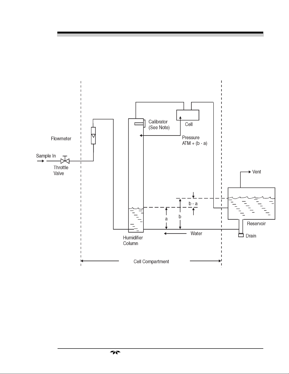
The analyzer flow system is shown schematically in Figure 1. It includes a needle valve for adjusting the sample flow rate, a flowmeter to
indicate the sample flow required for calibration, the humidifier, the calibrator, the measuring cell, and an automatic level control system for the water
in the humidifier.
As can be seen from Figure 1, the sample enters the humidifier column
against the pressure of a water column from the base of the humidifier to
the water level in the reservoir, which is approximately 4 inches. This
determines the minimum sample pressure at which any sample can flow
through the analyzer. In practice, the sample pressure must be somewhat
greater than this in order to have an adequate flow rate.
The automatic level control in the humidifier column is accomplished
by connecting the sample outflow from the cell to the bottom of the reservoir. The puts a back pressure on the sample in the cell and upper portion of
2-2
TELEDYNE ELECTRONIC TECHNOLOGIES
Analytical Instruments
TT
race Oxygrace Oxyg
T
race Oxyg
TT
race Oxygrace Oxyg
en Analen Anal
en Anal
en Analen Anal
yzyz
yz
yzyz
erer
er
erer
Operational Theory 2.0Operational Theory 2.0
Operational Theory 2.0
Operational Theory 2.0Operational Theory 2.0
Figure 1: Flow System Schematic
TELEDYNE ELECTRONIC TECHNOLOGIES
Analytical Instruments
2-3

2.0 Operational Theory2.0 Operational Theory
2.0 Operational Theory
2.0 Operational Theory2.0 Operational Theory
the humidifier column equal to the water column from the bottom of the
reservoir to the water level in the reservoir. Thus, the water level in the
humidifier column is held even with the sample connection at the bottom of
the reservoir. There will be a slight additional pressure in the top of the
humidifier column depending on the flow rate (the pressure needed to push
the sample through the cell and associated tubing), but at normal flow rates
this merely slightly lowers the level in the humidifier column.
The sample bubbles through the water in the reservoir on its way to the
outlet port. Some of the water vapor will re-condense, so that the sample
flows out of the outlet port saturated at the reservoir temperature, which is
slightly above ambient. The sample bubbling through the make-up water
will scrub out any oxygen which may be dissolved in it. This assures that the
sample will not pick up any oxygen as it passes through the humidifier
column.
Model 306WModel 306W
Model 306W
Model 306WModel 306W
AA
A
AA
2.4 Calibrator2.4 Calibrator
2.4 Calibrator
2.4 Calibrator2.4 Calibrator
The number of electrons flowing through the measuring cell’s load
resistance (the output current) is directly proportional to the amount of
oxygen that has reacted. If no oxygen is present, no output current flows,
giving the analyzer an absolute zero. No zero adjustment is required. The
analyzer can be completely calibrated with only one standard sample,
instead of the two usually required for process analyzers.
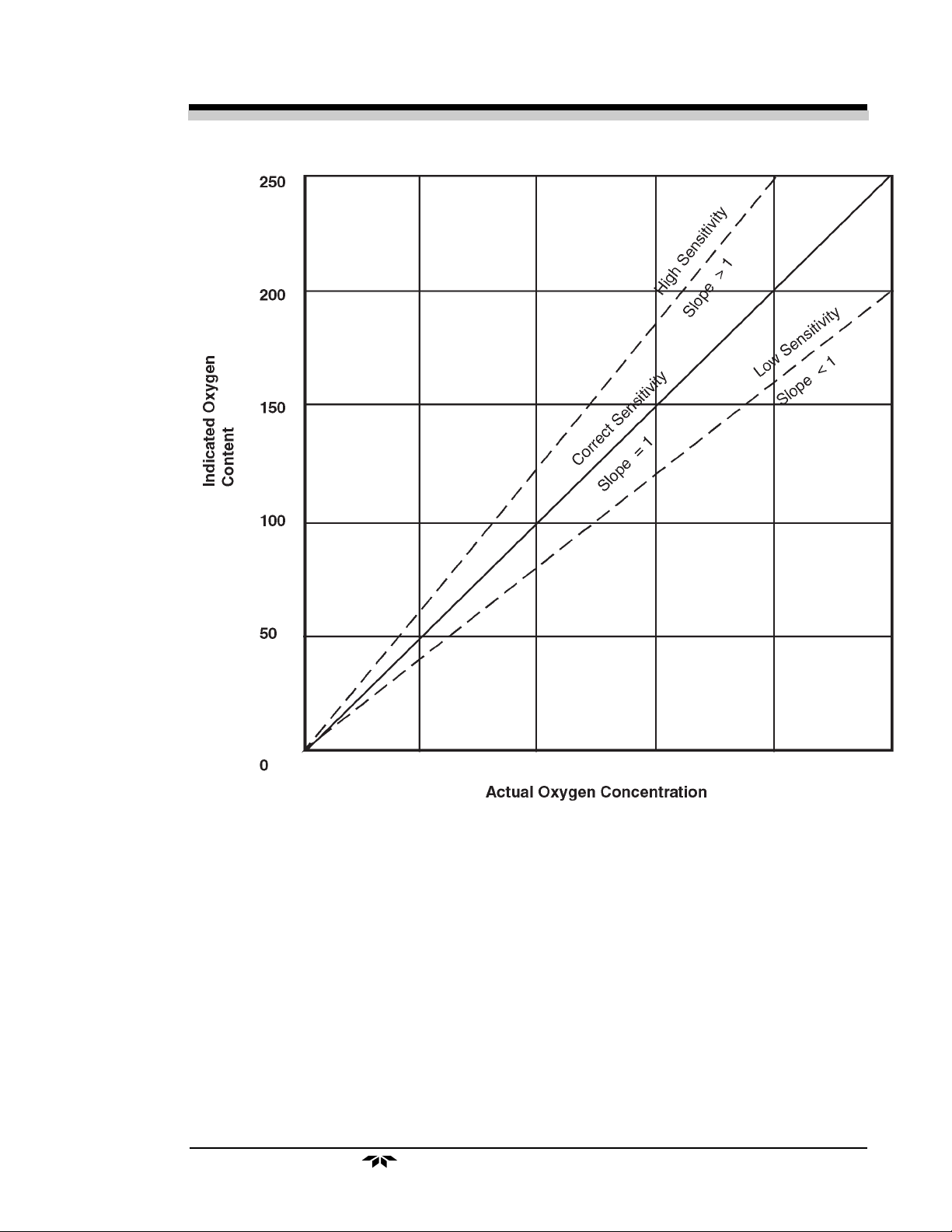
If the oxygen content indicated by the analyzer is plotted as ordinate
against the actual oxygen content as abscissa on a simple graph, the condition of proper calibration is represented by a straight line starting at the
origin with a slope of 1 (see Figure 2). If the analyzer has a low sensitivity,
the slope will be greater than 1. In each case, however, the line passes
through the origin because of the absolute zero, and the slope is determined
by the sensitivity adjustment. Thus, the analyzer can be completely calibrated by adjusting the slope of this curve; i.e., by adjusting the span so that
the change in output indication is equal to a known change in actual oxygen
content of the sample. This can be done by adding a known amount of
oxygen to the sample flowing through the analyzer, even though the amount
of oxygen in the sample is now known. Refer to section
4.7.1: Calibration4.7.1: Calibration
4.7.1: Calibration.
4.7.1: Calibration4.7.1: Calibration
The calibrator provided is an electrolysis cell in which water is converted to hydrogen and oxygen by an electric current.
The concentration of oxygen added to the sample can be calculated
from the amount of current passing through the calibrator and the sample
flow rate.
2-4
TELEDYNE ELECTRONIC TECHNOLOGIES
Analytical Instruments
TT
race Oxygrace Oxyg
T
race Oxyg
TT
race Oxygrace Oxyg
en Analen Anal
en Anal
en Analen Anal
yzyz
yz
yzyz
erer
er
erer
Operational Theory 2.0Operational Theory 2.0
Operational Theory 2.0
Operational Theory 2.0Operational Theory 2.0
Figure 2: Proper Calibration
TELEDYNE ELECTRONIC TECHNOLOGIES
Analytical Instruments
2-5

2.0 Operational Theory2.0 Operational Theory
2.0 Operational Theory
2.0 Operational Theory2.0 Operational Theory
The three ranges of the analyzer are intended primarily to make calibration convenient. It is expected that the oxygen content of the sample being
analyzed will be within the narrow range (Range No. 1) of the analyzer.
Then when the analyzer is switched to Range No. 2, a sufficiently large
amount of oxygen can be added by the calibrator to five a reliable calibration. Since the calibration is dependent on adjusting the change in indication, this change should be as large as possible—at least 50% of the wider
range.
For example:
Analyzer range: 0-1, 0-100, 0-1000
Sample reading: 18 PPM
Check calibration:
Adjust the analyzer calibration potentiometer so that 50 ppm of oxygen
is being added to the sample. This is the change in actual oxygen content of
the sample.
Model 306WModel 306W
Model 306W
Model 306WModel 306W
AA
A
AA
Assume that the analyzer changes its output to read 52.
The change in output indications is 52 - 18 = 34 when 50 PPM O2 is
added. Therefore, the span potentiometer should be adjusted to give a
reading of
(18 x 50) + 50 = 76.5 PPM
34
NOTE:NOTE:
NOTE:
NOTE:NOTE:
For details, see Appendix: Calibration Considerations.For details, see Appendix: Calibration Considerations.
For details, see Appendix: Calibration Considerations.
For details, see Appendix: Calibration Considerations.For details, see Appendix: Calibration Considerations.
2-6
TELEDYNE ELECTRONIC TECHNOLOGIES
Analytical Instruments

TT
race Oxygrace Oxyg
T
race Oxyg
TT
race Oxygrace Oxyg
en Analen Anal
en Anal
en Analen Anal
yzyz
erer
yz
er
yzyz
erer
InstallationInstallation
Installation
InstallationInstallation
3.1 Location3.1 Location
3.1 Location
3.1 Location3.1 Location
Installation 3.0Installation 3.0
Installation 3.0
Installation 3.0Installation 3.0
With proper shielding of the leads, the analyzer and the readout device
can be separated by as much as 1,000 feet. However, they should be placed
as close together as possible. For the most convenient operation, the readout recorder or meter should be within view of the controls, particularly
when the unit is being calibrated. Other location considerations:
1) The analyzer should be sheltered from the elements.
2) Ambient temperature must be within
30 to 120 °F.30 to 120 °F.
30 to 120 °F.
30 to 120 °F.30 to 120 °F.
3) The unit should not be subject to excessive shock or vibration.
4) It should be as close as possible to the sample point.
5) There must be access to the back and side of the unit for
connection or maintenance of sample lines and power.
NOTE:NOTE:
NOTE:
NOTE:NOTE:
Since the level of the electrolyte in the measuring cell is critical andSince the level of the electrolyte in the measuring cell is critical and
Since the level of the electrolyte in the measuring cell is critical and
Since the level of the electrolyte in the measuring cell is critical andSince the level of the electrolyte in the measuring cell is critical and
the water level control system for the humidifier is gravity sensitive,the water level control system for the humidifier is gravity sensitive,
the water level control system for the humidifier is gravity sensitive,
the water level control system for the humidifier is gravity sensitive,the water level control system for the humidifier is gravity sensitive,
THE ANALYZER MUST BE MOUNTED SO THAT THE BOTTOM OFTHE ANALYZER MUST BE MOUNTED SO THAT THE BOTTOM OF
THE ANALYZER MUST BE MOUNTED SO THAT THE BOTTOM OF
THE ANALYZER MUST BE MOUNTED SO THAT THE BOTTOM OFTHE ANALYZER MUST BE MOUNTED SO THAT THE BOTTOM OF
THE CASE IS LEVEL.THE CASE IS LEVEL.
THE CASE IS LEVEL.
THE CASE IS LEVEL.THE CASE IS LEVEL.
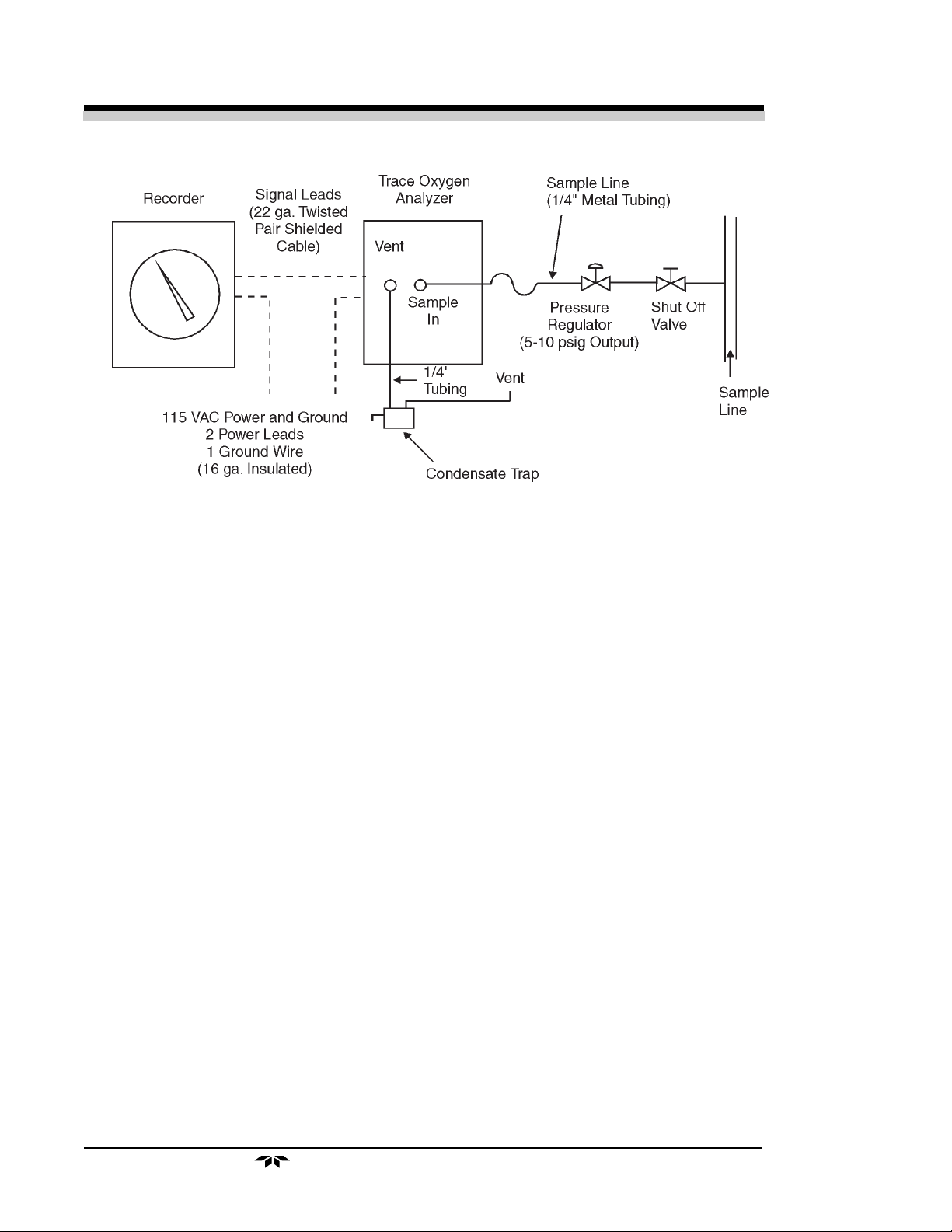
Figure 3 depicts a typical system layout.
3.2 Electrical Connections3.2 Electrical Connections
3.2 Electrical Connections
3.2 Electrical Connections3.2 Electrical Connections
A diagram of the necessary electrical connections is shown in Figure 4.
Note: Note:
Note:
Note: Note:
See the Interconnection Diagram (drawing A-21916) included in theSee the Interconnection Diagram (drawing A-21916) included in the
See the Interconnection Diagram (drawing A-21916) included in the
See the Interconnection Diagram (drawing A-21916) included in theSee the Interconnection Diagram (drawing A-21916) included in the
back of this manual, as well as any Addenda that may be includedback of this manual, as well as any Addenda that may be included
back of this manual, as well as any Addenda that may be included
back of this manual, as well as any Addenda that may be includedback of this manual, as well as any Addenda that may be included
with this manual for information specific to your instrument.with this manual for information specific to your instrument.
with this manual for information specific to your instrument.
with this manual for information specific to your instrument.with this manual for information specific to your instrument.
The connections include a terminal for grounding the analyzer case and
chassis in accordance with accepted industrial practices. The maximum
power requirement is less than
1½ amperes at 115 VAC1½ amperes at 115 VAC
1½ amperes at 115 VAC.
1½ amperes at 115 VAC1½ amperes at 115 VAC
TELEDYNE ELECTRONIC TECHNOLOGIE
Analytical Instruments
3-1
3.0 Installation3.0 Installation
3.0 Installation
3.0 Installation3.0 Installation
Model 306WModel 306W
Model 306W
Model 306WModel 306W
AA
A
AA
Figure 3: Typical System Layout
3.3 Sample Connections3.3 Sample Connections
3.3 Sample Connections
3.3 Sample Connections3.3 Sample Connections
The sample line is connected at the back of the analyzer case as depicted in Figure 5. Use care in assembling any part of the sampling system
to avoid leaks. Oxygen can diffuse into the system through small leaks even
when sample pressure is much greater than atmospheric pressure.
ConnectorsConnectors
1.
Connectors. Use straight tube connectors where possible.
ConnectorsConnectors
This facilitates removal of the analyzer section from the case
during maintenance or service.
LinesLines
2.
Lines. Lines should consist of metallic tubing, since oxygen can
LinesLines
diffuse through plastic. Use continuous tubing where possible.
VentVent
3.
Vent. The analyzed sample is vented through the back of the
VentVent
unit as shown in Figure 5.
The analyzer should have a vent line of ¼" diameter tubing at least two
feet long, running
air from diffusing into the reservoir and dissolving into the humidifier makeup water.
downwarddownward
downward from the vent connection. This is to prevent
downwarddownward
If it is not desirable to vent the sample into the atmosphere, a vent line
to carry the sample to a suitable venting area will be required. The sample
leaves the vent connection of the analyzer saturated with water vapor at a
temperature somewhat above ambient, so a suitable trap to remove condensate without plugging the vent line will be required. The vent line should
also be arranged so that it cannot become plugged by dirt or dust.
3-2
TELEDYNE ELECTRONIC TECHNOLOGIES
Analytical Instruments
 Loading...