

Page 1

Ultra Trace Sensor Model 3060E
TELEDYNE BROWN ENGINEERING
Analytical Instruments
MODEL 3060E
Ultra Trace Oxygen Analyzer
MODEL 3060E
ULTRA TRACE OXYGEN ANALYZER
INSTRUCTION MANUAL
TELEDYNE BROWN ENGINEERING
Analytical Instruments
MODEL 3060E
Ultra Trace Oxygen Analyzer
Software Version 4.22
Edition: M59174-94-554
P/N M59174
ECO# 96-385
May 24, 1996
Teledyne Electronic Technologies
Analytical Instruments
i
Page 2

Model 3060E Ultra Trace Sensor
Copyright © 1994 Teledyne Electronic Technologies/Analytical Instruments
All Rights Reserved. No part of this manual may be reproduced, transmitted,
transcribed, stored in a retrieval system, or translated into any other language or computer language in whole or in part, in any form or by any means, whether it be electronic, mechanical, magnetic, optical, manual, or otherwise, without the prior written
consent of Teledyne Brown Engineering Analytical Instruments, 16830 Chestnut Street,
City of Industry, CA 91749-1580.
Warranty
This equipment is sold subject to the mutual agreement that it is warranted by us
free from defects of material and of construction, and that our liability shall be limited
to replacing or repairing at our factory (without charge, except for transportation), or at
customer plant at our option, any material or construction in which defects become
apparent within one year from the date of shipment, except in cases where quotations or
acknowledgements provide for a shorter period. Components manufactured by others
bear the warranty of their manufacturer. This warranty does not cover defects caused by
wear, accident, misuse, neglect or repairs other than those performed by Teledyne or an
authorized service center. We assume no liability for direct or indirect damages of any
kind and the purchaser by the acceptance of the equipment will assume all liability for
any damage which may result from its use or misuse.
We reserve the right to employ any suitable material in the manufacture of our
apparatus, and to make any alterations in the dimensions, shape or weight of any parts,
in so far as such alterations do not adversely affect our warranty.
Important Notice
This instrument provides measurement readings to its user, and serves as a tool by
which valuable data can be gathered. The information provided by the instrument may
assist the user in eliminating potential hazards caused by his process; however, it is
essential that all personnel involved in the use of the instrument or its interface, with the
process being measured, be properly trained in the process itself, as well as all instrumentation related to it.
The safety of personnel is ultimately the responsibility of those who control
process conditions. While this instrument may be able to provide early warning of
imminent danger, it has no control over process conditions, and it can be misused. In
particular, any alarm or control systems installed must be tested and understood, both as
to how they operate and as to how they can be defeated. Any safeguards required such
as locks, labels, or redundancy, must be provided by the user or specifically requested of
Teledyne at the time the order is placed.
Therefore, the purchaser must be aware of the hazardous process conditions.
The purchaser is responsible for the training of personnel, for providing hazard warning
methods and instrumentation per the appropriate standards, and for ensuring that hazard
warning devices and instrumentation are maintained and operated properly.
Teledyne Electronic Technologies/Analytical Instruments (TET/AI), the
manufacturer of this instrument, cannot accept responsibility for conditions beyond its
knowledge and control. No statement expressed or implied by this document or any
information disseminated by the manufacturer or its agents, is to be construed as a
warranty of adequate safety control under the user’s process conditions.
ii
Teledyne Electronic Technologies
Analytical Instruments
Page 3

Ultra Trace Sensor Model 3060E
Table of Contents
1 Introduction
Overview ............................................................................................................ 1-1
Components ........................................................................................................ 1-2
Main Features of the Analyzer ........................................................................... 1-2
Applications........................................................................................................ 1-4
2 Operational Theory
Overview .............................................................................................................2-1
Ultra Trace Sensor ..............................................................................................2-3
Ultra Trace Sensor Components ..................................................................2-3
Ultra Trace Sensor Operation ......................................................................2-4
Faradaic Calibrator .............................................................................................2-5
Faradaic Calibrator Components .................................................................2-5
Faradaic Calibrator Operation .....................................................................2-7
Sample System ....................................................................................................2-8
Electronics ...........................................................................................................2-11
Signal Processing Functions.........................................................................2-12
Analog Input Circuit Board .................................................................2-12
AnalogOutput Circuit Board................................................................2-12
Digital Circuit Board ...........................................................................2-14
Display Screens....................................................................................2-14
Temperature Controller ................................................................................2-15
Valve Control Circuit Board ........................................................................2-15
Power Supply Module..................................................................................2-15
3 Installation
Overview .............................................................................................................3-1
Unpacking the Analyzer ......................................................................................3-1
Cautions and Warnings .......................................................................................3-2
Ultra Trace Sensor Installation............................................................................3-3
Adding Electrolyte to the Ultra Trace Sensor ..............................................3-4
Ultra Trace Sensor Electrical Connections ..................................................3-8
Teledyne Electronic Technologies
Analytical Instruments
iii
Page 4

Model 3060E Ultra Trace Sensor
Faradaic Calibrator .............................................................................................3-9
Adding Electrolyte to the Calibrator ............................................................3-10
Adding Water to the Reservoir.....................................................................3-14
Level Detector and Solenoid Switch ............................................................3-15
Electrical Installation...........................................................................................3-16
Electrical Connections..................................................................................3-16
Voltage Selection and Fuse Changing ..........................................................3-17
Gas Line Connections..........................................................................................3-19
Installation Checklist ...........................................................................................3-22
4 Operations
Overview .............................................................................................................4-1
Front Panel Controls and Indicators ....................................................................4-2
Sample System Status Panel ........................................................................4-2
LED Display ................................................................................................4-3
Computer Control Module ...........................................................................4-3
Sensor Compartment Temperature Controller .............................................4-6
Ultra Trace Sensor Electrolyte Temperature................................................4-6
Rear Panel Connections.......................................................................................4-6
Operating the Analyzer........................................................................................4-7
Start-up Checklist ........................................................................................4-7
Modes of Operation......................................................................................4-8
Cold Start 4-8
Warm Start ..........................................................................................4-9
Full Start Versus Quick Start ..............................................................4-9
Forcing a COLD START by turning Power OFF/ON .......................4-9
Forcing a Cold Start Without First Shutting Down .............................4-10
Full Start Mode ............................................................................................4-11
Full Start Options.........................................................................................4-13
Setup for Internal Calibrator Use (Full Start)......................................4-13
Setup for Span Gas Use (Full Start) ....................................................4-15
Setup for Both Span Gas & Internal Calibrator (Full Start)................4-16
Quick Start Mode.........................................................................................4-20
Analyze Mode ..............................................................................................4-23
Conditioning the Ultra Trace Sensor....................................................4-23
Span Calibration Using an External Span Gas ............................................4-25
Span Calibration Using the Internal Calibrator ...................................4-29
iv
Teledyne Electronic Technologies
Analytical Instruments
Page 5

Ultra Trace Sensor Model 3060E
Zero Calibration...................................................................................4-33
Important Notes on Zero and Span Calibration ...................................4-37
Setup Mode: System Password ....................................................................4-38
Setup: Alarms ......................................................................................4-40
Setup: Auto Settling ............................................................................4-42
Setup: Clock/Scheduled Span or Scheduled Zero ................................4-47
Setup: More Options ............................................................................4-49
Setup: H2O Reservoir ..........................................................................4-52
Setup: Modem ......................................................................................4-54
Setup: Zero/Span Gas Source ..............................................................4-55
Setup: Negative O2 ..............................................................................4-56
Range Mode .................................................................................................4-57
AutoRange Function ............................................................................4-57
Manual Range Function.......................................................................4-58
Stand-by Mode.............................................................................................4-58
Normal Shutdown ................................................................................4-59
High Current Output Mode ..........................................................................4-60
5 Maintenance & T roubleshooting
Routine Maintenance Checklist ...........................................................................5-1
Ultra Trace Sensor Maintenance .........................................................................5-1
Adding Distilled Water to the Electrolyte ....................................................5-1
Purging Distilled Water................................................................................5-2
Replacing the Electrolyte in the Ultra Trace Sensor ....................................5-3
Scrubber Maintenance .........................................................................................5-4
Troubleshooting...................................................................................................5-4
Troubleshooting Tables................................................................................5-5
6 Quick Reference
Introduction .........................................................................................................6-1
Cold Start ............................................................................................................6-4
Full Start ............................................................................................................. 6-5
Quick Start ..........................................................................................................6-6
Span Calibration Using External Gas Source .....................................................6-7
Span Calibration Using Internal Calibrator.........................................................6-8
Zero Calibration ..................................................................................................6-9
Setting the Password ...........................................................................................6-10
Teledyne Electronic Technologies
Analytical Instruments
v
Page 6

Model 3060E Ultra Trace Sensor
Setting the Alarms ...............................................................................................6-11
Auto Settling........................................................................................................6-12
Scheduled Zero and Scheduled Span ...................................................................6-13
Filtering, Zero Display, Bypass and Reservoir....................................................6-14
Modem.................................................................................................................6-15
Setup: Zero and Span Gas Source .......................................................................6-16
Negative Oxygen Display ....................................................................................6-17
Auto and Fixed Range .........................................................................................6-18
Standby: Normal Shutdown.................................................................................6-19
Appendix
Specifications ......................................................................................................A-1
Spare Parts List ...................................................................................................A-2
Drawing List........................................................................................................A-3
Material Safety Data Sheets............................................... MSDS-1
vi
Teledyne Electronic Technologies
Analytical Instruments
Page 7
IntroductionIntroduction
Introduction
IntroductionIntroduction
Overview
The Teledyne Electronic Technologies/Analytical Instruments (TET/AI) Model
3060E Ultra Trace Oxygen Analyzer is a highly sophisticated microprocessorbased instrument designed to measure the oxygen concentration in a gas
mixture in a range as low as 0-50 parts per billion (PPB). The 3060E accurately
measures and analyzes the oxygen content in inert gases such as helium,
nitrogen and argon, and in flammable gases such as hydrogen and ethylene. The
analyzer is easy to use through LCD menu displays with five touch switches for
operator interface.
Ultra Ultra
Ultra
Ultra Ultra
Introduction
483 mm
TT
race Oxygrace Oxyg
T
race Oxyg
TT
race Oxygrace Oxyg
en Analen Anal
en Anal
en Analen Anal
yzyz
yz
yzyz
erer
er
erer
SAMPLE
OXYGEN
SCRUBBER
13
CALIBRATOR
6
7
FLOWSET
SPARGER
BYPASS
1
10
2
MV1
3
CALIBRATOR
SAMPLE
SPAN
VENT1 VENT2
BYPASS
5
MV2
HO
2
8
N
2
AR
4
H
2
HE
SELECTOR
9
MV3
CELL
MFC
GAS
TELEDYNE BROWN ENGINEERING
Analytical Instruments
Model 3060E
ULTRA TRACE OXYGEN ANALYZER
SENSOR COMPARTMENT
35
83
51
310
82
35
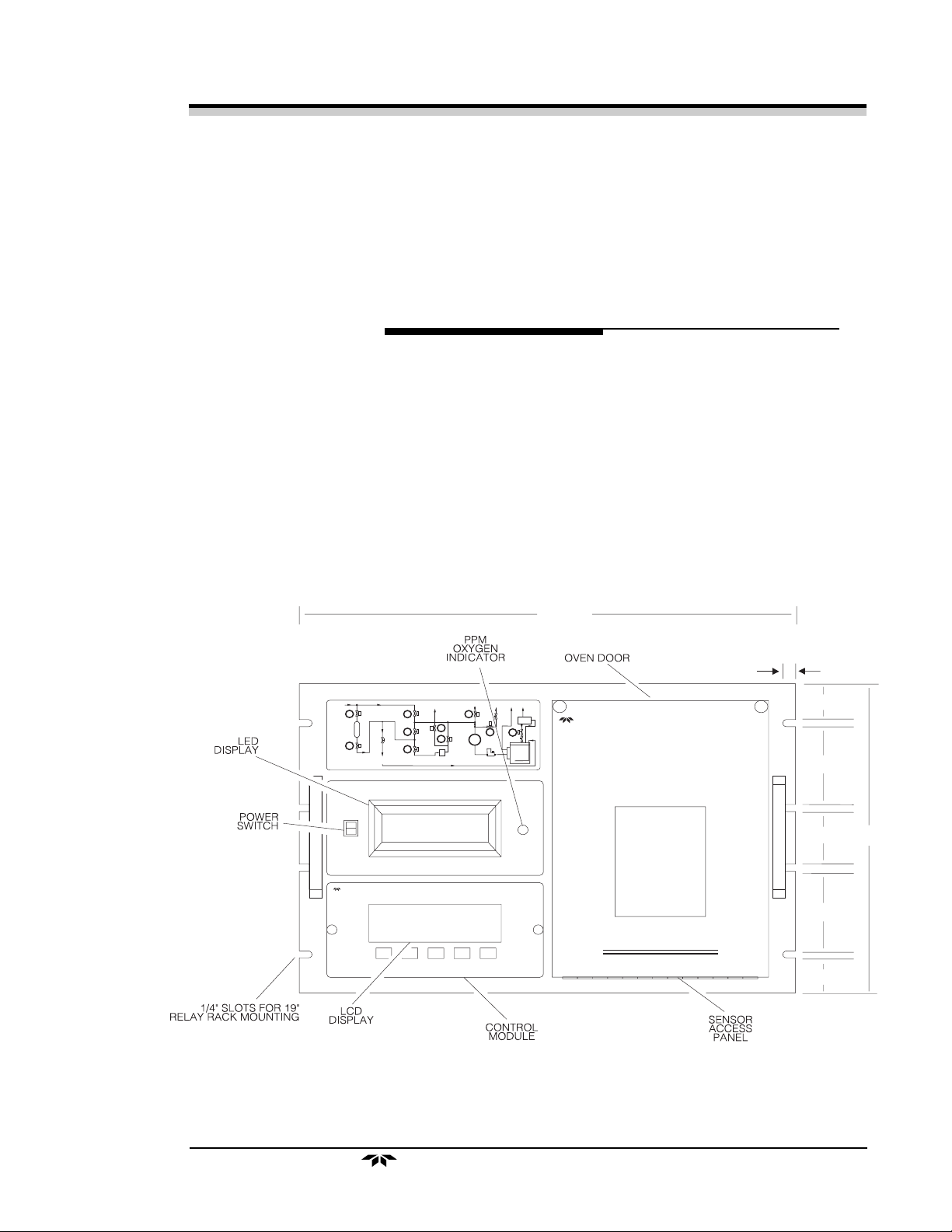
Figure 1-1: Model 3060E Front Panel
Teledyne Electronic Technologies
Analytical Instruments
1–1
Page 8

Model 3060EModel 3060E
Model 3060E
Model 3060EModel 3060E
Components
The 3060E is designed to mount in a standard 19-inch rack. All of the
operational controls are easily accessed through the well-marked front panel.
Each of the following components is contained within the analyzer:
• Analysis
Electrochemical Ultra Trace Sensor
Electrochemical Calibrator
Sample System
• Power Supply Module
• Control Module
• LED Display
• Valve Control Board
• Temperature Controller
Chapter 1Chapter 1
Chapter 1
Chapter 1Chapter 1
The external design consists of easily accessible controls and ports. The front
panel consists of:
• LED Display
• LCD Display
• Flow Schematic Display
• Ultra Trace Sensor Access Panel
The back panel ports are:
• Gas Inlet/Outlet Ports
• Electrical Connections
• Water Reservoir Inlet and Drain
Main Features of the Analyzer
The 3060E is highly sophisticated yet simple to use. Useful features help you
to operate the analyzer and also provide you with high quality analysis data.
Below is a list of the main features.
1. Low range (0–50 PPB): This range provides highest resolution and
accuracy for ultra-pure gases. Three other ranges (0–100 PPB, 0–1
PPM, and 0–10 PPM) are also provided to meet your analysis needs.
1–2
2. Linearity on all ranges: This feature allows the user to calibrate the
analyzer on any of the four ranges and then analyze the sample gases
for all ranges.
Teledyne Electronic Technologies
Analytical Instruments
Page 9

IntroductionIntroduction
Introduction
IntroductionIntroduction
3. AutoRanging with manual override: This feature allows the analyzer
4. Built-in oxygen scrubber: The built-in oxygen scrubber can be used
5. Faradaic calibrator: The built-in Faradaic calibrator generates oxy-
Ultra Ultra
Ultra
Ultra Ultra
to automatically select the appropriate range for a given measurement. A manual override allows the user to “lock in” a specific
range of interest.
to:
• Produce the zero gas needed to set the zero point.
• Feed the zero gas to sparge the electrolyte in the Ultra Trace
sensor.
• Feed the zero gas to the Faradaic calibrator to generate a
span gas for adjusting the span level.
Should very high oxygen levels be present in the sample gas, the
automatic scrubber inlet shut-off feature prolongs the life of the
scrubber.
gen from PPB levels up to 8 PPM, and allows the user to calibrate
the analyzer. A calibrator gauge logs the amount of time the calibrator is used and notifies you through the LCD display if the calibrator
electrolyte needs refilling.
TT
race Oxygrace Oxyg
T
race Oxyg
TT
race Oxygrace Oxyg
en Analen Anal
en Anal
en Analen Anal
yzyz
yz
yzyz
erer
er
erer
6. Autozero and Autospan: The analyzer can be set to calibrate itself
(zero and span) at pre-programmed intervals.
7. Span gas port: The analyzer has separate sample and span gas ports,
which allow the installation of an external source of span gas for
calibration without interfering with the sample gas line.
8. A built-in water/electrolyte level detector in the Ultra Trace sensor
signals an automatic water feed to the sensor when the electrolyte
falls below a minimum level.
9. Insensitivity to minor flow changes and mechanical vibrations: The
analyzer output is not affected by minor changes in the flow rate.
10. Built-in correction factors for various gases: Built-in correction
factors for various gases allow you to select nitrogen, argon, helium
or hydrogen as background gases without the need to recalibrate the
mass flow controller.
11. Flow schematic display: This feature allows you to visually verify
the exact status of each of the pneumatic valves in the sampling
system.
Teledyne Electronic Technologies
Analytical Instruments
1–3
Page 10

Model 3060EModel 3060E
Model 3060E
Model 3060EModel 3060E
12. Meter readouts (the analyzer includes two meter readouts):
13. Minimal maintenance: The electrochemical Ultra Trace sensor in the
analyzer requires virtually no maintenance. Water is automatically
replenished in the Ultra Trace sensor. Replacing the electrolyte is
easily done and does not require removing the Ultra Trace sensor
from the analyzer.
14. Remote capability: The 3060E can be remotely located and controlled from a microcomputer linked to the analyzer by a phone line.
Software provided with the analyzer allows you to control analyzer
functions through menus displayed on the computer.
15. Five direct-reading alarms: Five programmable setpoints and Form
C SPDT relays can be configured to practically any requirement.
Chapter 1Chapter 1
Chapter 1
Chapter 1Chapter 1
· A red LED readout with large, easy-to-read numerals
displaying oxygen concentration.
· An LCD graphic display which includes alphanumeric
information such as alarms, output, help menus, etc.
16. Isolated 4-20 mADC and 0-1 VDC (negative ground) outputs: Four
signal outputs provide for both oxygen measurement and range
identification.
Applications
The analyzer is an invaluable tool in the following applications and industries:
• Analysis of blanketing gases in semiconductor and electronics
industries.
• Measuring the purity of various gases in air separation plants.
• Controlling oxygen for cracking and heating furnaces in petrochemical industries.
• Prevention of oxidation by measuring the purity of blanketing gases
in fiber and glass industries.
• Monitoring and controlling gas atmospheres in the heat treatment of
metals in steel and other metal industries.
• Gas analysis and research in laboratories and research and development areas.
1–4
Teledyne Electronic Technologies
Analytical Instruments
Page 11

Operational Operational
Operational
Operational Operational
Overview
There are five main analyzer functional groups:
TheorTheor
Theor
TheorTheor
yy
y
yy
Operational Theory
1. Ultra Trace Sensor
2. Faradaic Calibrator
3. Sample System
Ultra Ultra
Ultra
Ultra Ultra
TT
race Oxygrace Oxyg
T
race Oxyg
TT
race Oxygrace Oxyg
en Analen Anal
en Anal
en Analen Anal
yzyz
yz
yzyz
erer
er
erer
4. Electronic Signal Processing
5. Temperature Controller.
The analyzer uses a sophisticated Ultra Trace oxygen (O2) sensor, which is an
electrochemical galvanic device with current output.
An electrochemical calibrator based on Faraday’s law is provided to facilitate
the calibration of the analyzer.
The sample system is designed to optimize the performance of the analyzer.
The components and the methods used for the fabrication of the sample system
assure leak-free transport of gases through the analyzer.
The electronic signal processing unit (control module) is designed to simplify
the operation of the analyzer and accurately process the signal from various
components. The control module incorporates a microprocessor which allows
the operation of the analyzer with a minimum of operator interaction.
A temperature controller regulates the temperature of the Ultra Trace sensor
to minimize the effects of ambient temperature variations during analysis.
Figure 2-1 shows the locations of the major components of the analyzer.
Teledyne Electronic Technologies
Analytical Instruments
2-1
Page 12

Model 3060EModel 3060E
Model 3060E
Model 3060EModel 3060E
Chapter 2Chapter 2
Chapter 2
Chapter 2Chapter 2
Figure 2-1. Main Components
Temperature
Controller
2-2
Teledyne Electronic Technologies
Analytical Instruments
Page 13
Operational Operational
Operational
Operational Operational
Ultra Trace Sensor
The analyzer incorporates an electrochemical ultra trace O2 sensor exclusively
designed by TET/AI (U.S. Patent #5,085,760). The sensor shows exceptionally high sensitivity for O2 and remarkable long-term stability. The highly
accurate sensing element of the sensor enables it to detect as low as 0.5 PPB
of O
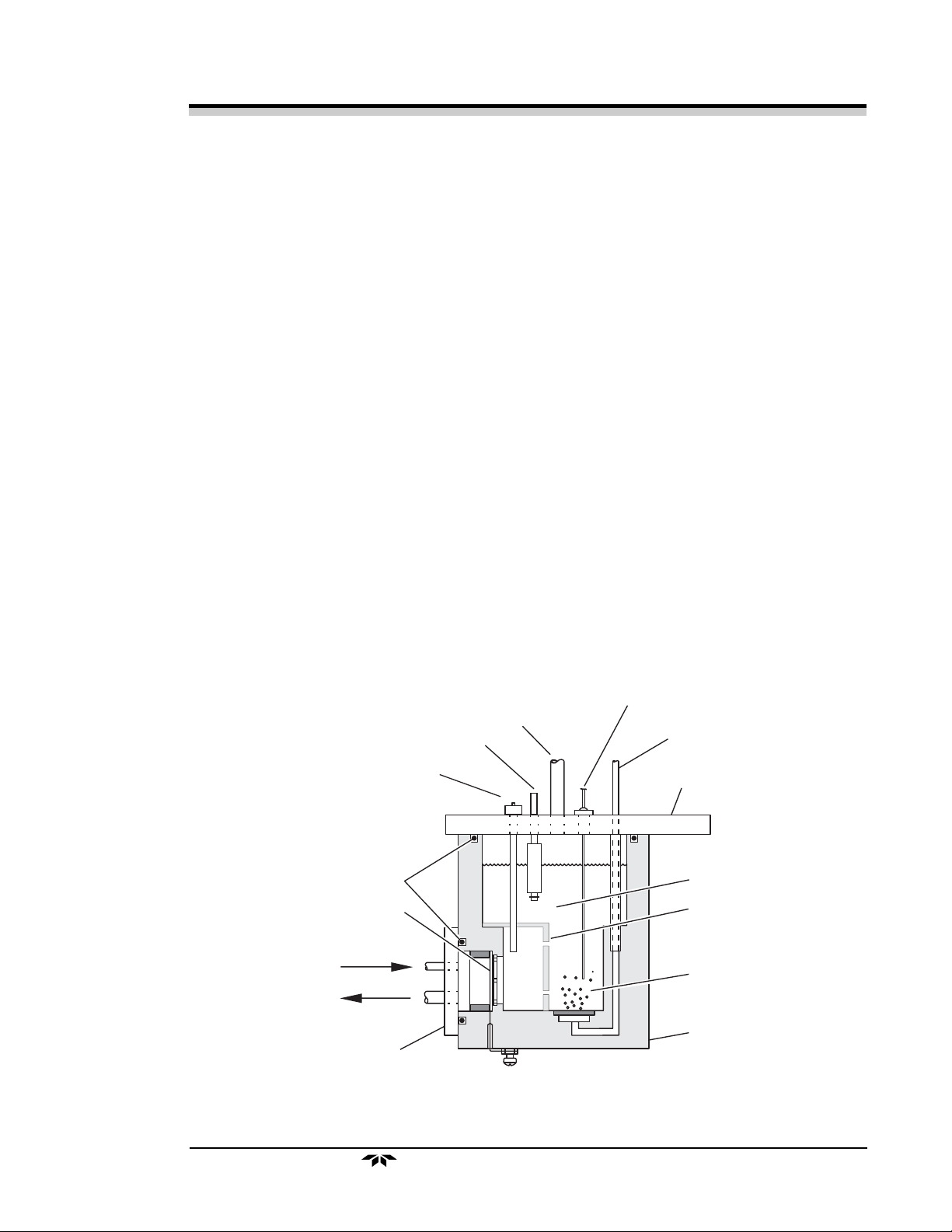
The components of the sensor are shown in Figure 2-2. The main body of the
sensor is made of clear acrylic. The sensor has a U-shaped profile with an open
top end. The left-hand wall of the sensor has a circular aperture for mounting
the O2-sensing cathode. A high surface area cadmium anode is inserted through
the top stainless steel plate. A fine porous frit disc is mounted at the bottom of
the sensor in order to remove any dissolved O2 by continuously sparging the
electrolyte with O2 free gas. A baffle plate is inserted between the sparger and
the sensing electrode to minimize the noise level caused by the sparger.
TheorTheor
Theor
TheorTheor
in a gas mixture.
2
yy
y
yy
Ultra Ultra
Ultra
Ultra Ultra
Ultra Trace Sensor Components
TT
race Oxygrace Oxyg
T
race Oxyg
TT
race Oxygrace Oxyg
en Analen Anal
en Anal
en Analen Anal
yzyz
yz
yzyz
erer
er
erer
The main body of the sensor contains 15% aqueous KOH electrolyte. A
thermistor is inserted into the sensor’s main body through an opening on the top
stainless steel mounting plate. The opening serves as a port for adding water/
electrolyte to the sensor. An electrolyte level detector is also mounted through
the top stainless steel plate.
WATER LEVEL
DETECTOR
CADMIUM ANODE
O-RING
CATHODE
SAMPLE IN
SAMPLE OUT
PURGE GAS OUT
(-)
THERMISTOR
PURGE GAS IN
TOP STAINLESS
STEEL PLATE
ELECTROLYTE
BAFFLE PLATE
ZERO GAS BUBBLES
(OXYGEN-FREE)
CELL BODY
SIDE STAINLESS
STEEL PLATE
Figure 2-2. Ultra Trace Sensor Components
(+)
CATHODE
Teledyne Electronic Technologies
Analytical Instruments
2-3
Page 14

Model 3060EModel 3060E
Model 3060E
Model 3060EModel 3060E
The sensing cathode used in the sensor is a high surface-area metal-catalyzed
gas diffusion electrode, with a surface area of 150–180 m2/g. A 0.4 mg/cm
catalyst load provides an effective cathode surface area of up to 600 times the
geometric area of the cathode. This produces a very high signal output per unit
concentration of O2; hence, an excellent signal-to-noise ratio is achieved even
at the highest sensitivity.
The metal-catalyzed gas-diffusion electrode consists of a hydrophobic Tefloncarbon gas diffusion backing layer and a Teflon-carbon metal catalyst layer
bonded together. The thickness of the catalyst layer is approximately one-tenth
of the gas diffusion layer. The overall thickness of the cathode is approximately
0.5 mm.
The cathode is held against the sensor body by a polyethylene ring. The catalyst
layer of the cathode is exposed to the electrolyte phase; the hydrophobic
backing layer is exposed to the gas to be analyzed. The cathode assembly is
sealed by placing a polypropylene O-ring between the stainless steel plate,
containing stainless steel gas inlet and outlet tubes, and the sensor body.
Chapter 2Chapter 2
Chapter 2
Chapter 2Chapter 2
2
The electrolyte in the sensor is continuously purged by bubbling the zero gas
(generated by passing the sample gas through the built-in scrubber) through the
fine porous frit mounted in the inner floor of the sensor. Sparging of the
electrolyte removes most of the dissolved O
from the electrolyte, reducing the
2
background signal.
Ultra Trace Sensor Operation
The gas to be analyzed enters the cavity through an inlet tube between the
cathode and the stainless steel plate, and exits through the outlet tube. During
this process, the gas diffuses through the gas wicks of the hydrophobic backing
layer, and reaches the catalyst surface where O2 present in the gas mixture reacts
by the following mechanism:
O2 + 2H2O + 4e- → 4OH
Due to the high surface area of the catalyst, most of the O2 reacts at the cathode
surface and a very small amount of O2 dissolves in the bulk electrolyte. The
continuous sparging of the electrolyte with zero gas does not allow the O
concentration to build up in the bulk electrolyte. The amount of O2 that reaches
the catalyst surface is proportional to the partial pressure of O2 in the gas
mixture.
-
(cathode)
2
2-4
Teledyne Electronic Technologies
Analytical Instruments
Page 15

Operational Operational
Operational
Operational Operational
When the O2 is reduced at the cathode, cadmium is simultaneously oxidized by
the following mechanism:
TheorTheor
Theor
TheorTheor
yy
y
yy
Ultra Ultra
Ultra
Ultra Ultra
TT
race Oxygrace Oxyg
T
race Oxyg
TT
race Oxygrace Oxyg
en Analen Anal
en Anal
en Analen Anal
yzyz
yz
yzyz
erer
er
erer
Cd → Cd+2 + 2e
The electrons released at the anode surface flow to the cathode surface via an
external circuit. This current is measured and used to determine the O
concentration in the gas mixture. The resulting current is directly proportional
to the O2 level in the gas mixture.
The current output of the sensor changes with temperature therefore, in order
to minimize the effects of ambient temperature variation on the current output,
the sensor is housed in a temperature-controlled oven maintained at 28°C
±2°C. Variations in temperature affecting the sensor are detected by a resistive
thermal device (RTD) attached to the sensor, which signals the temperature
controller to adjust the oven temperature accordingly.
A thermistor installed in the sensor monitors electrolyte temperature. Changes
in electrolyte temperature above 30°C are relayed to the microprocessor, which
adjusts the current output through a compensation algorithm.
NOTE: Since the gas to be analyzed does not flow through the bulk
electrolyte of the sensor, the probability of contaminating the
electrolyte by the particulates (if any) in the sample gas is very low.
This eliminates the requirements for frequent replacement of
sensor electrolyte. This is in contrast to Hercsh type galvanic cells
where gas is bubbled through the electrolyte and frequent replacement of electrolyte (3-6 month intervals) is essential to maintain
sensor performance.
-
(anode)
2
Faradaic Calibrator
The analyzer may be calibrated by using either the internal Faradaic calibrator
or an external span gas. The calibration using an external span gas is simple and
self-explanatory. The internal calibrator generates O2 at a precisely controlled
rate. The unique design of the calibrator allows repeated and reliable calibration
of the analyzer.
Faradaic Calibrator Components
Figure 2-3 illustrates major calibrator components. The calibrator is comprised
of a top electrode assembly and a bottom mounting block containing a cup for
electrolyte. An O-ring is used to make a leak-free seal between these two
components.
Teledyne Electronic Technologies
Analytical Instruments
2-5
Page 16
Model 3060EModel 3060E
Model 3060E
Model 3060EModel 3060E
The two platinum/gold wire electrodes are attached to a feed-through header,
which is sealed to the stainless steel plate. The two electrodes are wrapped
around a porous polyethylene rod. The bottom end of the porous polyethylene
rod is submerged into the pool of electrolyte. Capillary action causes the
electrolyte to fill the pores, keeping the electrodes wet, which helps to maintain
the ionic conductivity between the two electrodes.
O
N
P
O
W
E
R
TE
LE
DYN
A
NA
E
LYTIC
AL
INS
TR
UM
EN
TS
PPBO XYGEN
P
P
M
O
X
Y
G
E
N
Chapter 2Chapter 2
Chapter 2
Chapter 2Chapter 2
C
O
N
T
R
O
L
M
O
D
U
L
E
2-6
Figure 2-3. Major Calibrator Components
Teledyne Electronic Technologies
Analytical Instruments
Page 17

Operational Operational
Operational
Operational Operational
The calibrator is based on Faraday’s Law of Electrolysis. When applied to the
electrolysis of water, it states that the rate at which oxygen is generated is
directly proportional to the quantity of electric current flowing through the
electrodes. Based on this, the following formula is derived to determine the
current required to generate a mixture with the desired oxygen concentration
(PPM) and flow rate (SCCM).
The desired O2 concentration is entered through the calibration menu, and the
mass flow controller provides the flow rate of O2-free zero gas through the
calibrator. The required current for the electrolysis of water is calculated by the
microprocessor and then supplied to the calibrator electrodes.
A calibrator bypass uses zero gas to flush out any O2 that has seeped into the
calibration cavity path, eliminating excess O2 that might otherwise enter the
sampling system.
TheorTheor
Theor
TheorTheor
yy
y
yy
Ultra Ultra
Ultra
Ultra Ultra
Faradaic Calibrator Operation
µµ
I (
µA) = 40/150 X O2 (PPM) X Flow Rate (SCCM)
µµ
TT
race Oxygrace Oxyg
T
race Oxyg
TT
race Oxygrace Oxyg
en Analen Anal
en Anal
en Analen Anal
yzyz
yz
yzyz
erer
er
erer
The accuracy of the calibration gas formed using the calibrator is best in the
0-10 PPM range. Since the sensor has linear output through all ranges, the
analyzer may be calibrated at one or two ranges above the normal range of
operation.
NOTE: For example, if the analyzer is to be used for analysis in the 0–50
PPB range, calibrate the analyzer in the 0–100 PPB or 0–1 PPM
range to minimize calibration error. At this level, errors due to
mass flow controller calibration, measurement of current from a
current source and current leakage are minimized.
To see why, assume the absolute error during calibration on any range is 2 PPB.
If the analyzer is calibrated at 25 PPB, 2 PPB error constitutes an 8% error in
calibration. However, if the analyzer is calibrated at 80 PPB the calibration
error will be only 2.5%.
Teledyne Electronic Technologies
Analytical Instruments
2-7
Page 18

Model 3060EModel 3060E
Model 3060E
Model 3060EModel 3060E
Sample System
The sample system delivers gases to the O2 sensor from the analyzer rear panel
inlet. Depending on the mode of operation (determined by which valves are
open or closed), either a sample, span or zero gas is delivered.
Chapter 2Chapter 2
Chapter 2
Chapter 2Chapter 2
The 3060E sample system is designed and fabricated to insure that the O
concentration of the gas is not altered (except in the O2 scrubber) as it travels
through the sample system.
• Electropolished 316L Stainless Steel Components
To eliminate O2 absorption and desorption from the internal wetted
surfaces of the sample system components, the sample system is
fabricated from electropolished 316L stainless steel.
• Welding/Metal Gasket-Type Fittings
All of the joints upstream of the O2 sensor are orbitally welded,
except for the metal gasket-type compression connections at the O
scrubber and mass flow controller. Orbital welding is used in the
sample system wherever feasible. Orbital welding fuses the electropolished 316L stainless steel components together, forming a
smooth, clean internal (wetted) weld junction and eliminating small
spaces around the weld junction where gases can get trapped or
absorbed. All of the weld junctions in the entire assembly are
purged using an inert gas during welding to ensure that there is no
O2 contamination.
Orbital welding is used where practical; otherwise, conventional
precision welding is used. For example, conventional precision
welding is used to fuse the tubes to the mounting plates. Metal
gasket-type compression connections are used at the O2 scrubber
and at the mass flow controller to facilitate replacement. The metal
gasket-type connection creates an airtight, metal-to-metal seal,
eliminating inboard and outboard gas leakage.
2
2
2-8
Teledyne Electronic Technologies
Analytical Instruments
Page 19

Operational Operational
Operational
Operational Operational
TheorTheor
Theor
TheorTheor
• Valves
yy
y
yy
The analyzer sampling system utilizes three different types of valves.
Each valve is selected to prevent O2 contamination of the sample
depending on its position and purpose in the circuit.
Air-Actuated Bellows Valves
These valves are normally closed in the sample system. They are
used to control the delivery through the sample system of the
sample, span or zero gas. The valve bodies are orbitally welded
in the system and the valve bonnets make a metal-to-metal seal
to the body. This valve system eliminates inboard and outboard
gas leakage. The valves are activated (open/closed) by computer-controlled solenoid valves.
The valves have the following basic functions:
PV1: Sample gas to the Ultra Trace sensor.
PV2: Zero gas to the Ultra Trace sensor.
PV3: Zero gas to the calibrator.
PV4: Span gas out of the calibrator.
PV5: External span gas to the Ultra Trace sensor.
PV6: Sample gas into the scrubber.
PV7: Zero gas out of the scrubber.
PV8: Sample bypass vent.
PV9: Water to the Ultra Trace sensor.
PV10: Calibration bypass.
Ultra Ultra
Ultra
Ultra Ultra
TT
race Oxygrace Oxyg
T
race Oxyg
TT
race Oxygrace Oxyg
en Analen Anal
en Anal
en Analen Anal
yzyz
yz
yzyz
erer
er
erer
Metering Valve
The metering valve (labeled MV1 on the flow schematic) is used
to manually control the sparge rate to the sensor. The body of
the metering valve is orbitally welded and the bonnet is sealed to
the body with metal O-rings. The manual control knob is located in the sensor compartment.
Solenoid Valves
The solenoid valves control the air flow to the air-activated
bellows valves. The solenoid valves are controlled by the microprocessor. When de-energized, the valve outlet is open to
ambient air, allowing the air-activated bellows valve to close.
Teledyne Electronic Technologies
Analytical Instruments
2-9
Page 20

Model 3060EModel 3060E
Model 3060E
Model 3060EModel 3060E
• Oxygen Scrubber
The O2 scrubber is used to remove O2 (down to less than 1 PPB,
typically 0.5 PPB) from the sample gas. The scrubbed gas is used
for:
Sparging
Electrolyte in the Ultra Trace oxygen sensor is sparged with
oxygen-free gas to reduce dissolved oxygen from the electrolyte.
Zero Calibration
The oxygen-free gas is used to electronically offset the background signal of the Ultra Trace sensor. This provides a zero
point for the system to measure the oxygen content of the
sample gas during analysis.
Span Calibration Using Internal Calibrator
Chapter 2Chapter 2
Chapter 2
Chapter 2Chapter 2
The oxygen-free gas is mixed with oxygen generated in the
electrochemical calibrator to produce a span gas with a known
oxygen concentration. This provides a span point for the system
to measure the oxygen content of the sample during analysis.
NOTE: The standard O2 scrubber has a capacity of 80 cc of pure O2 .
Under normal operating conditions, the scrubber is expected to
last several years. The scrubber is installed in the system using
metal gasket and VCR type fittings.
The life of the scrubber is approximately 10 years when subjected
to an O2 concentration of 10 PPM at a flow rate of 150 cc/min.
• Mass Flow Controller
A mass flow controller is used to control the rate of gas flowing by
the sensing electrode of the sensor. The flow controller is located
upstream of the sensor. It provides signal input to the electronics in
the control module. The flow rate is displayed on the LCD screen
and is typically set at 150 cc/min.
• Fittings
The electropolished 316L stainless steel tees, elbows and crosses
used in the sampling system are orbitally welded for system integrity.
Small size fittings are used to make the sample system compact and
to minimize total system internal volume.
2-10
Teledyne Electronic Technologies
Analytical Instruments
Page 21
Operational Operational
Operational
Operational Operational
TheorTheor
Theor
TheorTheor
yy
y
yy
Ultra Ultra
Ultra
Ultra Ultra
TT
race Oxygrace Oxyg
T
race Oxyg
TT
race Oxygrace Oxyg
en Analen Anal
en Anal
en Analen Anal
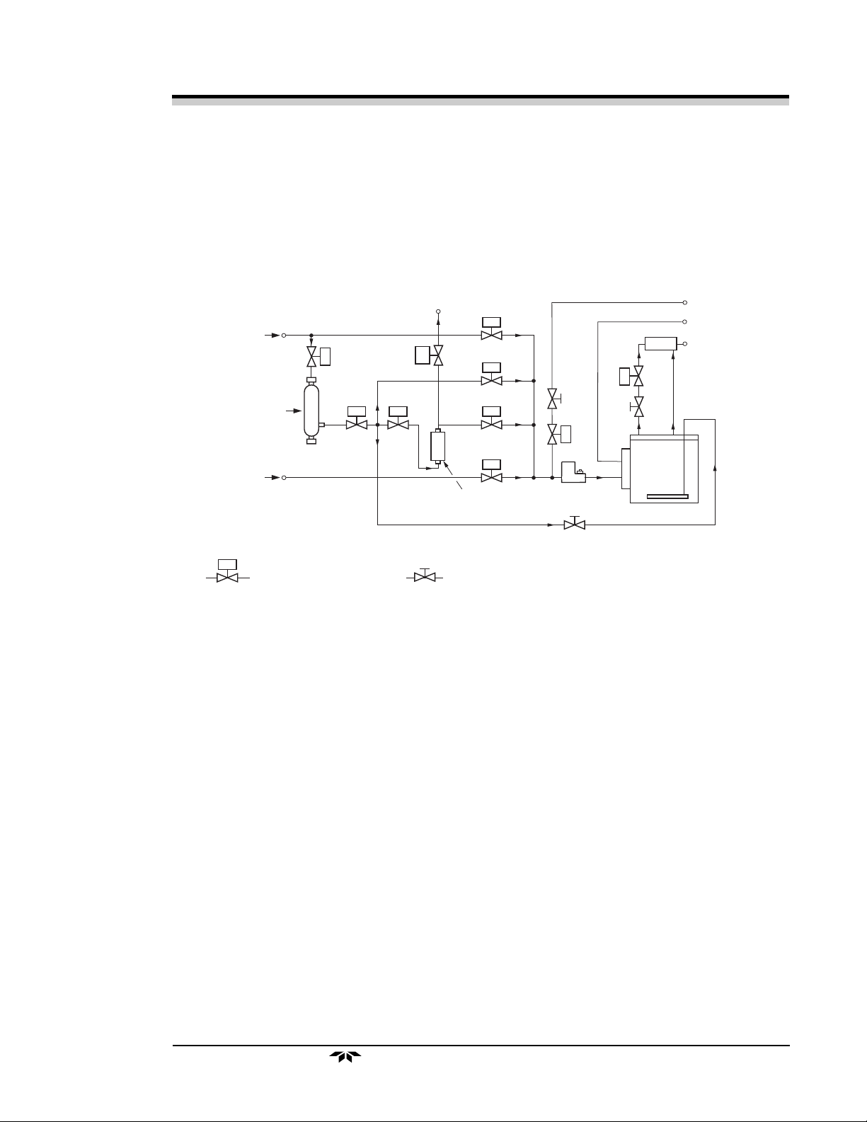
• Overall Sample System Design
The design of the sample system minimizes the volume of dead
space, which can retain residual gas from another route or previous
mode of analysis. Dead space contamination is minimized by the
structure of the gas flow routes (Figure 2-4).
yzyz
yz
yzyz
erer
er
erer
SAMPLE IN
OXYGEN SCRUBBER
SPAN GAS IN
PV
1
SHUT-OFF VALVE METERING
Electronics
The analyzer has an embedded microcomputer, that controls all signal processing, input/output and display functions of the analyzer. System power is
supplied from a power supply module designed to be compatible with any
international power source.
PV
CALIBRATOR
BYPASS
6
PV
7
10
PV
3
CALIBRATOR
MV1
Figure 2-4. Flow Schematic
PV
PV
PV
PV
1
2
4
5
VALVE
MV2
8
MV1
PV
9
ULTRATRACE
SENSOR
H2O
MV3
BYPASSVENT (SAMPLE)
VENT #1 (SAMPLE/SPAN)
VENT #2 (SPARGER)
The microcomputer, a liquid crystal display (LCD) and all analog signal
processing electronics are located inside a replaceable control module. A light
emitting diode (LED) display and circuitry to actuate the valves in the sample
are located outside the control module.
Functional groups of analyzer electronics are:
1. Signal Processing
2. Temperature Control
3. Valve Control
4. Power Supply
Teledyne Electronic Technologies
Analytical Instruments
2-11
Page 22

Model 3060EModel 3060E
Model 3060E
Model 3060EModel 3060E
Signal Processing Functions
Analog signal processing is accomplished in two plug-in circuit cards operating
under control of the microcomputer. One card processes analog input signals
and the other processes analog output signals. Digital signal processing is
accomplished directly by the microcomputer. All analog signals are converted
to digital early in the processing cycle to minimize analog processing and assure
maximum system accuracy, since digital processing is much more accurate than
analog and immune to many parameters such as drift and aging.
Analog Input Circuit Board
The analog input printed circuit board (PCB) is actually a plug-in module
consisting of a main board and a daughter board. Two analog signals are
connected to the inputs of this module for processing. They are:
• Ultra Trace Sensor Current Output
• Mass Flow Controller Output
Chapter 2Chapter 2
Chapter 2
Chapter 2Chapter 2
The circuitry on the daughter board converts the Ultra Trace sensor current to
a corresponding voltage, provides range control, isolates system grounds, and
filters high frequencies from the signal.
The circuitry on the main board processes the filtered output signal from the
daughter board and the signal outputs from the flow controller. All signals are
eventually connected through an analog multiplexer (electronic switch) to the
input of an analog-to-digital converter, where they are converted to digital
signals for use by the microcomputer.
This circuit board also contains a voltage measuring circuit to monitor the
voltage outputs of the system power supply, and a gas selector switch circuit
to adjust the mass flow controller for the background gas selected.
Analog Output Circuit Board
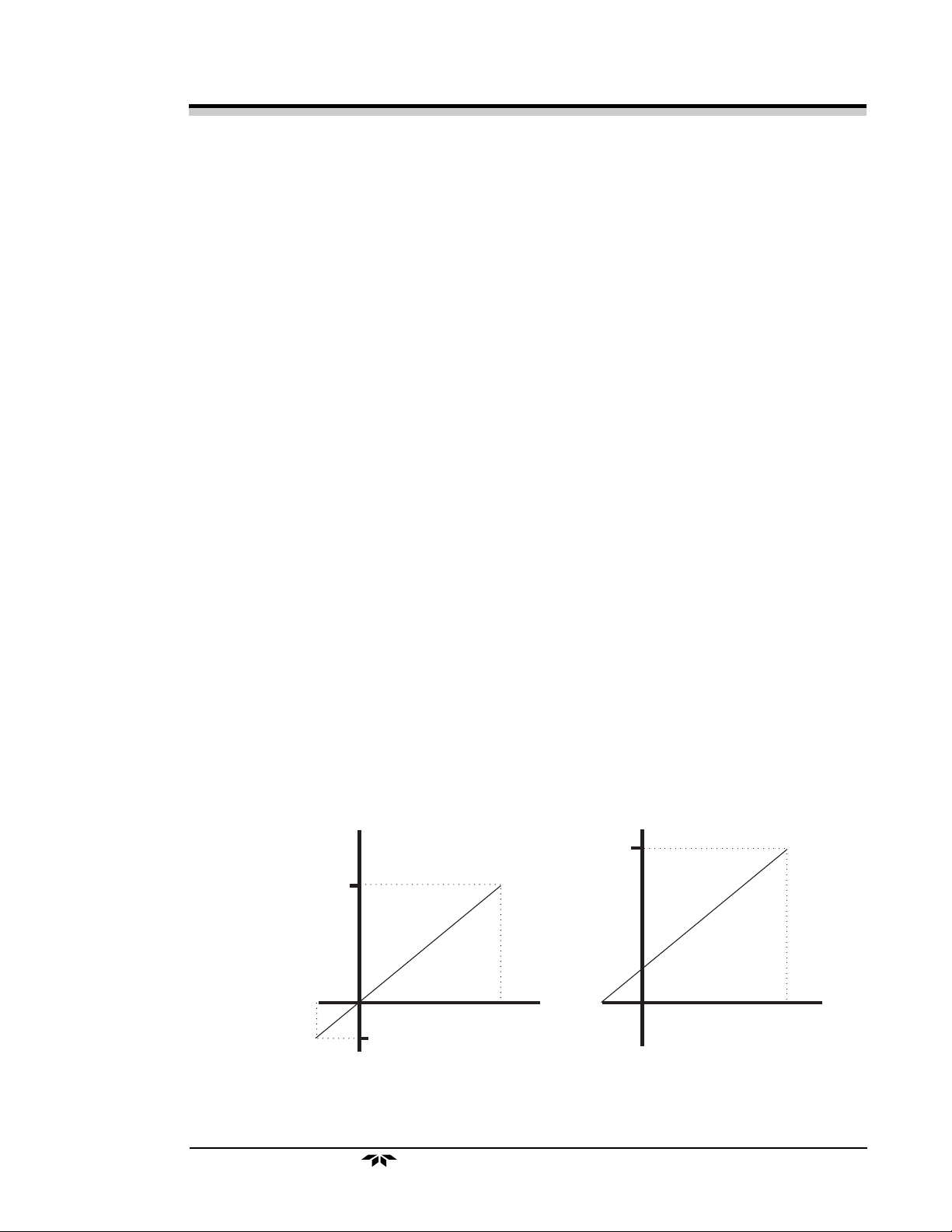
The analog output printed circuit board (PCB) generates the two 0-1 volt and
the two 4-20 mA analog signal outputs available on the rear panel of the
analyzer. These signals, generated in digital format by the microcomputer, are
converted into analog signals by the circuitry on this PCB. The output signals
represent the following:
• 0-1V Signal (Oxygen Measurement)
2-12
This output goes from 0 to 1, representing 0 to 100% of the scale
that has been set; i.e., 0.6 volt is equal to 60% of the full scale, or 30
PPB when on the 50 PPB scale. It is possible that the signal may go
past zero into the negative range up to -0.25, especially if the ana-
Teledyne Electronic Technologies
Analytical Instruments
Page 23
Operational Operational
Operational
Operational Operational
TheorTheor
Theor
TheorTheor
yy
y
yy
Ultra Ultra
Ultra
Ultra Ultra
TT
race Oxygrace Oxyg
T
race Oxyg
TT
race Oxygrace Oxyg
en Analen Anal
en Anal
en Analen Anal
lyzer has been zeroed with a gas that contains a significant concentration of O2 (Figure 2-3).
• 0-1V Range Identifier
This 0 to 1 volt output represents each range with a particular
voltage as shown in Table 2-1.
• Isolated 4-20 mA Signal (Oxygen Measurement)
This is a 4 to 20 mA output representing 0 to 100% of the scale,
with 4 mA equal to 0%, and 20 mA equal to 100% of that range.
This output may also range lower than 4 mA, especially if the
analyzer has been zeroed with a gas that contains a significant
concentration of O2 (Figure 2-5).
• Isolated 4-20 mA Range Identifier
This 4 to 20 mA output identifies individual ranges with discrete
current output as shown in Table 2-1.
yzyz
yz
yzyz
erer
er
erer
1 V
- 1/4
Full Scale
Value
Identifier Identifier
Range Voltage (V) Current (mA)
50 PPB 0.0 4.0
100 PPB 0.2 7.2
1 PPM 0.4 10.4
10 PPM 0.6 13.6
30 PPM 0.8 16.8
Table 2-1. Range Identifier
Voltage (V)
20 mA
O2
(0,0)
-0.25
Full
Scale
- 1/4
Full
Scale
Value
Current (I)
O2
(0,0)
Full
Scale
Figure 2-5. Analog Signal Output Offset
Teledyne Electronic Technologies
Analytical Instruments
2-13
Page 24

Model 3060EModel 3060E
Model 3060E
Model 3060EModel 3060E
Digital Circuit Board
The digital PCB is a general purpose microcomputer used to control all
functions of the analyzer. The analog input PCB and the analog output PCB
plug directly into connectors located on the digital PCB. In addition to
controlling these analog PCBs, the digital board performs the following
functions:
1. Provides valve control commands for the sampling system.
2. Processes input from the control panel pushbuttons.
3. Provides signals for the selectable alarms.
4. Processes serial I/O functions (RS-232 data). The following serial
interface default parameters are used:
Defaults
1200 Baud Fixed
8 Bits
No Parity
1 Stop Bit
Chapter 2Chapter 2
Chapter 2
Chapter 2Chapter 2
5. Controls the LCD and the LED displays.
Display Screens
There are two display screens on the front panel of the analyzer:
LCD
This screen is a dot-matrix display located on the control module of the
analyzer. It displays all of the menus and commands for the user to
control the system and is the user interface for system operations.
LED
This screen is a 7-segment display located on the front panel of the
analyzer, above the control module. This screen displays only oxygen
concentration, but it is large and bright to allow the operator to read it
at a greater distance. A dimmer switch for this display is located on the
display PCB behind the front panel.
2-14
Teledyne Electronic Technologies
Analytical Instruments
Page 25

Operational Operational
Operational
Operational Operational
Temperature control in the oven, which houses the sensor and Faradaic
calibrator, is processed by a stand-alone proportional integrative derivative
(PID) controller. Input from the resistive thermal device (RTD) sensor located
in the oven is used to regulate two 25-watt heaters. Oven temperature is set at
28 ±2°C and should be kept at this temperature during analyzer operation.
The valve control PCB is external to the control module, across the top of the
front panel of the analyzer. This PCB contains driver circuitry to activate the
solenoid valves. It also contains and controls dual-color LEDs that indicate the
actual status of the pneumatic valves (green for OPEN and red for CLOSED).
The valve control PCB operates under the control of the system microcomputer.
TheorTheor
Theor
TheorTheor
yy
y
yy
T emperature Controller
Valve Control Circuit Board
Ultra Ultra
Ultra
Ultra Ultra
TT
race Oxygrace Oxyg
T
race Oxyg
TT
race Oxygrace Oxyg
en Analen Anal
en Anal
en Analen Anal
yzyz
yz
yzyz
erer
er
erer
Power Supply Module
NOTE: This power supply contains an International Power Entry Module.
This feature allows operation on any of four international voltage
ranges: 100V, 120V, 220V or 240V (50Hz or 60Hz). It also
facilitates both North American and European fusing arrangements. Instructions for programming this module are described in
Chapter 3, Voltage Selection.
The analyzer power supply module is a replaceable assembly containing four
power supplies and five alarm relays. Electronic circuitry used to drive and
interface the alarm relays to the output of the microcomputer is also located
inside this module.
Teledyne Electronic Technologies
Analytical Instruments
2-15
Page 26

Model 3060EModel 3060E
Model 3060E
Model 3060EModel 3060E
Chapter 2Chapter 2
Chapter 2
Chapter 2Chapter 2
2-16
Teledyne Electronic Technologies
Analytical Instruments
Page 27

InstallationInstallation
Installation
InstallationInstallation
Overview
Installation of the analyzer includes:
Ultra Ultra
Ultra
Ultra Ultra
TT
race Oxygrace Oxyg
T
race Oxyg
TT
race Oxygrace Oxyg
en Analen Anal
en Anal
en Analen Anal
Installation
1. Unpacking the system.
2. Recognizing the necessary precautions when installing the system.
3. Adding electrolyte to the Ultra Trace sensor.
4. Adding electrolyte to the calibrator.
5. Hooking up electrical connections.
6. Hooking up the sample/span gas and instrument air supply to the
appropriate connections.
7. Testing the system.
yzyz
yz
yzyz
erer
er
erer
Unpacking the Analyzer
Carefully unpack the analyzer and inspect it for damage. Immediately report
any damage to the shipping agent. Remove the packing slip and verify that you
have received all of the correct materials.
Packing list:
1. Model 3060E Ultra Trace Oxygen Analyzer
2. 3060E Accessory Kit (P/N A59582)
The analyzer is shipped with all the materials and special items you need to
install and prepare the system for operation. The shipping carton contains the
following components:
1. Analyzer assembly
• Ultra Trace sensor
• Calibrator
• Two cadmium anodes (in holders)
• Electronics
Teledyne Electronic Technologies
Analytical Instruments
3-1
Page 28

Model 3060EModel 3060E
Model 3060E
Model 3060EModel 3060E
2. Standard accessory kit for the 3060E (P/N A59582):
Qty P/N Description
12 G284 Gaskets, VCR-type
6 G352 Weld glands, male, VCR-type
6 N284 Nuts, female
5
7
/64 "
/16 "
1 W66 Wrench, open end, ¼ " 1 S915 Screwdriver, #0 Phillips drive
1 S916 Screwdriver, slotted drive
1 S914 Socket, 7/16 " for ¼ " drive
1 R1549 Rachet, quick release, ¼ " drive
1 W68 Allen wrench, with handle, 7/64 "
1 W69 Allen wrench, long arm,
1 A51934 KOH electrolyte
1 A64239 Calibration electrolyte
1 B51752 Syringe 50 cc (Assembled)
1 A51886 Syringe 2 cc (Assembled)
1 T1052 Fritted glass tube
1 Safety glasses
1 pr. Gloves, rubber
1 MP-A56133 Procedure for Preparation of Electrolyte
Chapter 3Chapter 3
Chapter 3
Chapter 3Chapter 3
3. Instruction Manual
4. Quick Reference: Start Up
Cautions and Warnings
1. Always use extreme care when handling the electrolyte bottles.
Electrolyte can cause skin irritation. If the electrolyte comes into
contact with skin, immediately wash the affected area with cold
water.
CAUTION: The sensor electrolyte is caustic. Protective equipment
including, but not limited to, gloves and safety glasses should
be worn while handling electrolyte. See the Material Safety
Data Sheets for potential hazards and corrective action in
case of accident.
2. Use the correct syringe for each type of electrolyte. The 50 cc
syringe is used with the sensor electrolyte. The 2 cc syringe is used
with the calibrator electrolyte.
3. Before adding electrolyte to the sensor, examine the electrical
connections on the sensor body to make sure that they are firmly
secured to the proper terminals.
3-2
Teledyne Electronic Technologies
Analytical Instruments
Page 29
InstallationInstallation
Installation
InstallationInstallation
Ultra Trace Sensor Installation
The analyzer is usually shipped with the sensor installed. If you need to install
or replace the sensor assembly before using the analyzer, use the procedure
below.
Ultra Ultra
Ultra
Ultra Ultra
TT
race Oxygrace Oxyg
T
race Oxyg
TT
race Oxygrace Oxyg
en Analen Anal
en Anal
en Analen Anal
4. When adding electrolyte to the calibrator, do not overfill.
5. When hooking up electrical connections, do not connect the output
to the chassis.
6. Do not begin operating the analyzer until you have completed all of
the installation procedures.
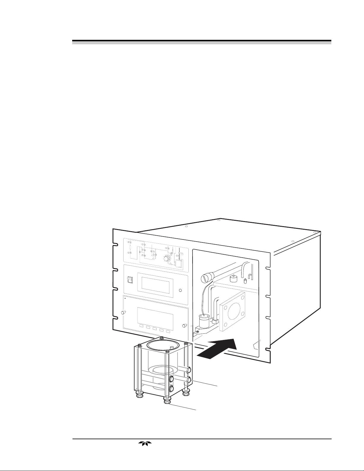
1. Prepare the analyzer casing for the sensor. Place four of the short
bolts in the holes on the side of the sensor and four of the long bolts
in the holes at the bottom of the sensor and bring the sensor between
the top and side stainless steel plates (see Figure 3-1). Leave all
eight bolts loose until Step 3.
yzyz
yz
yzyz
erer
er
erer
O
N
P
O
W
E
R
PPM O
X
YG
PPB O
T
E
L
E
D
Y
N
E
A
N
A
L
Y
T
I
C
A
L
I
N
S
T
R
U
M
E
XYG
N
T
S
EN
C
O
N
T
R
O
L
M
O
D
U
L
E
EN
SIDE BOLTS
BASE BOLTS
Figure 3-1. Ultra Trace Sensor Bolt Installation
Teledyne Electronic Technologies
3-3
Analytical Instruments
Page 30

Model 3060EModel 3060E
Model 3060E
Model 3060EModel 3060E
2. Slip the Teflon tubing (mounted inside the sensor) onto the 1/8 "
stainless steel tube at the bottom of the stainless steel top plate (see
Figure 3-2).
Chapter 3Chapter 3
Chapter 3
Chapter 3Chapter 3
Figure 3-2. Tube Alignment
3. Push the sensor all the way up against the top stainless steel plate.
4. Finger-tighten the side and then the bottom bolts with your hand.
5. Using the rachet (RL547) supplied, tighten each of the four bolts to
secure the sensor to the top plate.
6. Using the rachet (RL547) supplied, tighten each of the four bolts on
the side plate.
NOTE: Make sure that the O-rings are in their grooves on the top and side
of the sensor before tightening the bolts.
Adding Electrolyte to the Ultra Trace Sensor
CAUTION: Protective equipment including but not limited to gloves,
safety glasses, face shield and rubber apron must be worn
while handling electrolyte. The safety of the people in the
vicinity of the area in which the electrolyte is being handled
must be given similar consideration. Please refer to Material
Safety Data Sheets to learn about potential hazards and
corrective action in case of accident.
3-4
Teledyne Electronic Technologies
Analytical Instruments
Page 31

InstallationInstallation
Nitrogen
Teflon/Nylon
tube
Fritted tube
P/N T1052
Electrolyte
bo ttle
P/N BT L-P-32OZ
KOH
electrolyte
Nitrogen
bubbles
Installation
InstallationInstallation
Prior to adding electrolyte to the Ultra Trace sensor, the electrolyte must be
purged with nitrogen (N2) to remove most of the dissolved oxygen (O2). This
will reduce the time required to remove the dissolved O
by sparging it with N
purge the electrolyte:
Ultra Ultra
Ultra
Ultra Ultra
inside the sensor and hence, shorten the start-up time. To
2
1. Prepare the sensor electrolyte by following procedure MP-A56133
included in the Accessory Kit.
2. Open the cap of the electrolyte bottle.
3. Insert the fritted glass tube (P/N T1052) through the opening in the
bottle and bubble O
of the N
can be seen dispersing through the electrolyte.
should be adjusted so that a large number of small bubbles
2
-free N2 through the electrolyte. The flow rate
2
TT
race Oxygrace Oxyg
T
race Oxyg
TT
race Oxygrace Oxyg
from the electrolyte
2
en Analen Anal
en Anal
en Analen Anal
yzyz
yz
yzyz
erer
er
erer
Figure 3-3. Electrolyte Bottle with Fritted Tube
4. Purge the electrolyte for about one hour.
NOTE: TET/AI recommends that the sensor be purged before adding
electrolyte. This is done by lowering a plastic/Teflon tube (clean
and free of any oil/grease and/or particulates) into the sensor
through the opening on the top of the stainless steel mounting plate
and flushing the sensor with O2-free gas. Add electrolyte into the
sensor while flushing the sensor with O2-free gas. This will
eliminate the O2 from the sensor before the addition of prepurged
electrolyte. This procedure will substantially reduce the downtime
associated with clean-up at the first startup of the analyzer.
Teledyne Electronic Technologies
Analytical Instruments
3-5
Page 32

Model 3060EModel 3060E
Model 3060E
Model 3060EModel 3060E
After the electrolyte has been purged, it can be added to the sensor using the
following procedure:
1. Remove the plastic screw cap from the anode port on the stainless
steel plate on the top of the sensor body (Figure 3-4.1) and flush out
the sensor by using oxygen-free gas.
Gas Out
Oxygen-Free
Gas In
Plastic/Teflon
Tube
Chapter 3Chapter 3
Chapter 3
Chapter 3Chapter 3
3-6
Figure 3-4.1. Flushing Out the Ultra Trace Sensor by O2-Free Gas
2. Insert the tube attached to the 50 cc syringe into the electrolyte
bottle and slowly fill the syringe with electrolyte.
3. Insert the tube attached to the syringe into the sensor through the
opening on the top stainless steel plate. Slowly pour electrolyte into
the sensor (Figure 3-4.2).
Teledyne Electronic Technologies
Analytical Instruments
Page 33

InstallationInstallation
Installation
InstallationInstallation
ELECTROLYTE
ANODE
PORT
TOP
Ultra Ultra
Ultra
Ultra Ultra
TT
race Oxygrace Oxyg
T
race Oxyg
TT
race Oxygrace Oxyg
CELL BODY
en Analen Anal
en Anal
en Analen Anal
yzyz
yz
yzyz
erer
er
erer
Figure 3-4.2. Adding Electrolyte to the Ultra Trace Sensor
NOTE: Review the cautions and warnings on the use of electrolyte at
the beginning of this chapter and in the Material Safety Data
Sheets.
Avoid spilling electrolyte on the stainless steel plate. If you spill
any electrolyte on the stainless steel plate, wipe it up with damp
tissue paper. If electrolyte is not completely wiped, a white
residue (potassium carbonate, a reaction product of potassium
hydroxide and carbon dioxide in air) will appear with time.
As you pour, ensure that no large air bubbles remain trapped
inside the sensor. If large bubbles appear, use the syringe to
withdraw electrolyte from the sensor until the bubbles disappear. Return the withdrawn electrolyte to the sensor slowly.
4. Add electrolyte until the level reaches about 1 inch above the yellow
level marker on the front of the Ultra Trace sensor body. DO NOT
add electrolyte above the green level marker.
5. Remove the cadmium anode from the holder and immediately insert
it into the sensor through the opening in the top mounting plate
(Figure 3-5). Ensure that the O-ring is attached to the anode assembly.
Teledyne Electronic Technologies
Analytical Instruments
3-7
Page 34

Model 3060EModel 3060E
Model 3060E
Model 3060EModel 3060E
ELECTROLYTE
ANODE
PORT
TOP
CELL BODY
Chapter 3Chapter 3
Chapter 3
Chapter 3Chapter 3
Figure 3-5. Inserting the Anode
Ultra Trace Sensor Electrical Connections
There are two wires to be connected so that the sensor can send signals to the
central processor to generate the O2 content data, and two wires to send
temperature data to the processor.
The cathode terminal is located at the bottom of the sensor body and connected
to the red wire. The anode connection is on top of the sensor and is connected
to the black wire. The thermistor terminal is mounted on the stainless steel plate
on the top of the sensor body. With the exception of the anode, each of these
terminals is already connected to the signal processing unit when the analyzer
is shipped.
The positive and negative current source leads for the calibrator are located on
the top of the calibrator assembly (Figure 3-6).
After installing the analyzer, examine all of the connectors to ensure that they
are firmly secured to their respective terminals.
3-8
Teledyne Electronic Technologies
Analytical Instruments
Page 35

InstallationInstallation
Installation
InstallationInstallation
Ultra Ultra
Ultra
Ultra Ultra
TT
race Oxygrace Oxyg
T
race Oxyg
TT
race Oxygrace Oxyg
*
Some instruments have
a switch mounted here for
toggling solenoid valve 9
(see Status Panel) on and
off. See Section 3.4.3
The two wires from the switch
*
are connected so as to short
between the white/red wires
of the level detector
en Analen Anal
en Anal
en Analen Anal
yzyz
yz
yzyz
erer
er
erer
Figure 3-6. Sensor Cell Components and Connections
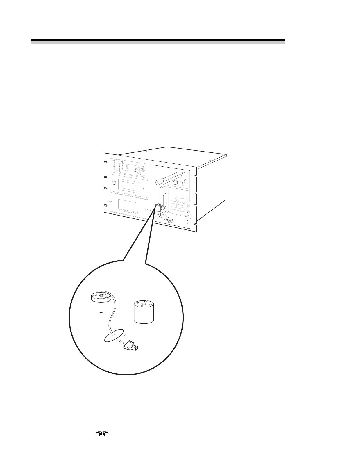
Faradaic Calibrator
The Faradaic calibrator is located inside the Ultra Trace sensor compartment.
The calibrator consists of a stainless steel block with a Teflon liner inside the
block and an electrode assembly. In order to use the Faradaic calibrator, you
must add electrolyte to the Teflon calibrator liner.
Adding the recommended amount of calibration electrolyte (about 1/2 c c) to the
calibrator generally enables you to use the calibrator for about 10 hours. A
countdown timer in the upper right-hand corner of the LCD keeps track of the
amount of time the calibrator has been used in a hh:mm format. A flashing
“C=0:00” on the display indicates that the calibrator needs refilling.
Teledyne Electronic Technologies
Analytical Instruments
3-9
Page 36

Model 3060EModel 3060E
Model 3060E
Model 3060EModel 3060E
NOTE: If you try to use the calibrator with insufficient electrolyte or
without the current source leads connected, the LCD will display CURRENT FAILURE MODE. If this occurs, refill the
calibrator with calibrator electrolyte, connect the current source
leads, and turn the analyzer OFF and then ON. Proceed with
the Quick Reference: Start Up and perform the calibration
again (see Chapter 4 for details).
O
N
P
O
W
E
R
P
P
M
O
X
Y
G
E
TELEDYNE
ANALYTICALINSTRUMENTS
P
P
B
O
X
Y
G
E
N
N
Chapter 3Chapter 3
Chapter 3
Chapter 3Chapter 3
CONTROLMODULE
Calibrator current
source connector
Figure 3-7. Removing the Calibrator Assembly.
Adding Electrolyte to the Calibrator
CAUTION: Calibration electrolyte is not the same as the Ultra Trace
sensor electrolyte. Calibration electrolyte is a combination of
an aqueous 0.5% CF3SO3H and an ionic surfactant. Do not
use the aqueous 15% KOH electrolyte (Ultra Trace sensor
electrolyte) in the calibrator. Using the Ultra Trace sensor
electrolyte in the calibrator will seriously damage the calibrator and the sampling system valves.
3-10
Teledyne Electronic Technologies
Analytical Instruments
Page 37

InstallationInstallation
Installation
InstallationInstallation
WARNING: Protective equipment including but not limited to gloves,
Ultra Ultra
Ultra
Ultra Ultra
TT
race Oxygrace Oxyg
T
race Oxyg
TT
race Oxygrace Oxyg
en Analen Anal
en Anal
en Analen Anal
yzyz
yz
yzyz
safety glasses, face shield and rubber apron must be worn
while handling electrolyte. The safety of the people in the
vicinity of the area in which the electrolyte is being handled
must be given similar consideration. Please refer to Material
Safety Data Sheets to learn about potential hazards and
corrective action in case of accident.
ON
P
O
W
E
R
T
E
L
E
D
A
Y
N
N
A
E
L
Y
T
I
C
A
L
I
N
S
T
R
U
M
PPMOXYGEN
PPBOXYGEN
E
N
T
S
C
O
N
T
R
O
L
M
O
D
U
L
E
erer
er
erer
Figure 3-8. Adding Electrolyte to the Calibrator.
Teledyne Electronic Technologies
Analytical Instruments
3-11
Page 38

Model 3060EModel 3060E
Model 3060E
Model 3060EModel 3060E
The analyzer is shipped with the calibrator electrode assembly installed. In
order to add electrolyte to the calibrator, the electrode assembly must be
removed from the calibrator block. To remove the calibrator electrode
assembly, use the following procedures:
1. Disconnect the current source connector from the calibrator assembly.
2. Using the wrenches (W68 and W69) provided, unscrew the four
bolts from the top of the calibrator assembly (see Figure 3-7).
3. Lift up and remove the calibrator electrode holder. To avoid contaminating the electrodes, do not touch the calibrator wick and
avoid contact between the wick and the calibrator block. Place the
calibrator electrode holder on a flat surface with the calibrator wick
facing upward.
4. Using the 2 cc micro-syringe supplied, add 1/2 cc of the calibration
electrolyte to the calibrator housing by lowering the micro-syringe
needle into the center of the Teflon liner in the stainless steel block
(see Figure 3-8).
Chapter 3Chapter 3
Chapter 3
Chapter 3Chapter 3
CAUTION: Avoid spilling electrolyte on the stainless steel block. If you
spill any electrolyte on the stainless steel block, wipe it up with
a damp tissue paper.
If the electrolyte has entered between the Teflon liner and the
stainless steel block, remove the electrolyte from the Teflon
liner and then remove the Teflon liner by using a clean screw
driver pushing against the liner and pulling it up. Clean the
inside of the stainless steel block and the outside of the Teflon
liner with tissue paper. Insert the Teflon liner in the stainless
steel block and carefully refill it with calibration electrolyte.
Do not add more than 1/2 cc electrolyte to the calibrator. If you
overfill the calibrator and electrolyte enters the gas manifold,
it can damage the Ultra Trace oxygen sensor, the flow
controller, and the valves.
5. After adding electrolyte to the calibrator housing, rinse the calibrator
wick with distilled water.
6. With the syringe, carefully put a few drops of electrolyte onto the
entire wick including the portion under the electrodes and wait until
the wick absorbs some of the electrolyte (see Figure 3-9).
3-12
7. Gently shake the electrode assembly to remove any excess electrolyte on the calibrator wick.
Teledyne Electronic Technologies
Analytical Instruments
Page 39

InstallationInstallation
Installation
InstallationInstallation
NOTE: DO NOT wipe the wick with a tissue paper.
Ultra Ultra
Ultra
Ultra Ultra
TT
race Oxygrace Oxyg
T
race Oxyg
TT
race Oxygrace Oxyg
en Analen Anal
en Anal
en Analen Anal
8. Place the calibrator electrode assembly back on the stainless steel
block.
9. Using the wrench (P/N W68) provided, secure the calibrator electrode assembly on the stainless steel block by tightening the four
bolts and then tighten the bolts with the wrench (P/N W69) provided. See Figure 3-10.
10. Reconnect the current source connector to the calibrator.
O
N
P
O
W
E
R
P
P
M
O
X
Y
G
E
N
P
P
B
O
X
Y
G
E
T
N
E
L
E
D
A
Y
N
N
A
E
L
Y
T
I
C
A
L
I
N
S
T
R
U
M
E
N
T
S
CO
N
TR
O
L
M
O
D
U
L
E
yzyz
yz
yzyz
erer
er
erer
Figure 3-9. Soaking the Calibrator Wick with the Electrolyte.
O
N
POWER
P
P
M
O
X
Y
G
E
PPBOXYGEN
T
E
L
A
E
N
D
A
Y
L
N
Y
E
T
IC
A
L
IN
S
T
R
U
M
E
N
T
S
C
O
N
T
R
O
L
M
O
D
U
N
L
E
Ca librator
current source
connector
Figure 3-10. Installing the Calibrator.
Teledyne Electronic Technologies
Analytical Instruments
3-13
Page 40

Model 3060EModel 3060E
Model 3060E
Model 3060EModel 3060E
Adding Water to the Reservoir
If the analyzer is to be used continuously for on-line gas analysis, then add
approximately 800 cc of distilled water to the reservoir. The rate of water
addition to the sensor is controlled by the metering valve MV3 located adjacent
to the reservoir, below the top cover plate. The valve MV3 is also accessible
from the rear of the analyzer.
The water drip rate is set at the factory at 1 drop every 2–4 minutes. This drip
rate is close to the rate of evaporation of water from the Ultra Trace sensor.
However, if the water drip rate is not proper, the electrolyte level in the Ultra
Trace sensor will not be maintained at the desired level (between the yellow and
green level markers). A drip rate that is too slow will cause the electrolyte level
to drop slowly. If this occurs, open MV3 slightly (1/2 turn) by rotating the valve
control knob anticlockwise. See Figure 3-11 for the location of MV3. Repeat
this step if necessary.
Chapter 3Chapter 3
Chapter 3
Chapter 3Chapter 3
Figure 3-11. Piping Layout, Water Reservoir and Metering Valves
CAUTION: If you open valve MV3 too wide, an excessive amount of water
will enter the sensor and the output will increase but will
slowly return to the original value. With MV3 open too wide,
the level detector will open and close more frequently causing
output instability. If this occurs, close MV3 slowly until the
drip rate is normal. If you experience difficulty in adjusting
MV3, you may add prepurged water directly to the sensor
through the filler port.
3-14
Teledyne Electronic Technologies
Analytical Instruments
Page 41

InstallationInstallation
Installation
InstallationInstallation
The water in the reservoir should last for 8-12 months. Check the water level
periodically by dipping a glass rod into the reservoir. When the water level falls
below
the top surface of the reservoir.
CAUTION: Do not completely fill the reservoir with water; this will
If the analyzer is to be used as a transportable unit, i.e., on a cart for certifying
various points at an installation, do not add water into reservoir but instead add
prepurged water directly into the sensor when the electrolyte level has fallen
below the yellow level marker on the sensor.
Ultra Ultra
Ultra
Ultra Ultra
1
/2 inch, add more water until the level is approximately 1/2 - 1/4 inch below
prevent the sensor sparge gas from being vented through the
water reservoir and may force the sparge gas to flow through
the sensing electrode of the sensor and cause electrolyte
leakage.
TT
race Oxygrace Oxyg
T
race Oxyg
TT
race Oxygrace Oxyg
en Analen Anal
en Anal
en Analen Anal
Level Detector and Solenoid Switch
yzyz
yz
yzyz
erer
er
erer
The level detector senses when the electrolyte level in the sensor drops, usually
as a result of water evaporation. When this occurs, a solenoid valve (valve 9
on the Status Panel) opens and replenishes the lost water at a rate depending
on the relative opening of metering valve MV3.
Ocassionally, trapped air between the solenoid valve (valve 9) and the metering
valve (MV3) will prevent the automatic addition of water to the sensor even
though the level detector is sensing a low electrolyte condition and the solenoid
valve is open. In some units, a toggle switch has been installed as shown in
Figure 3-6 which when switched off and on several times, causes the solenoid
valve (valve 9) to open and close repeatedly and dislodges any trapped gas. In
units without this toggle switch, repeated opening and closing of the solenoid
valve is accomplished through the software.
For the units with the toggle switch, the switch should be left in the ON position
for normal operation. Moving the toggle switch to the OFF position causes the
solenoid valve to close. If trapped gas is suspected, alternately opening and
closing the solenoid valve by switching the toggle switch off and on several
times will create a slight pressure pulse and drive out any trapped pockets of
air.
NOTE: The toggle switch must be left in the ON position for normal
operation. If the switch is left in the OFF position, the water
replenishing solenoid valve (valve 9) will remain closed regardless
of the electrolyte level in the sensor. Opening MV3 will have no
effect on the electrolyte level. Instability and damage to the Ultra
Trace sensor will eventually result as the electrodes become dry.
Teledyne Electronic Technologies
Analytical Instruments
3-15
Page 42

Model 3060EModel 3060E
Model 3060E
Model 3060EModel 3060E
Electrical Installation
Electrical Connections
All of the electrical connections originate at the back of the analyzer (see Figure
3-15). The analyzer is shipped with all of the electrical connections intact.
There is no assembly or installation required. The four output signal connectors
are screw terminals for two wires per output and polarity is noted below each
set of terminals. The five alarm circuit connectors are screw terminals for alarm
relay contacts which are noted below each set of terminals.
The five selectable alarms provide a set of Form C contacts. The contacts are
capable of switching up to 3 amperes at 115 VAC into a resistive load.
The RS-232 port is configured as data terminal equipment (DTE) and uses a
9-pin D connector wired as follows:
Chapter 3Chapter 3
Chapter 3
Chapter 3Chapter 3
Pin # Signal
1 No connection
2 Transmit Data
3 Receive Data
4 N/C
5 Ground
6 N/C
7 RTS
8 CTS
9 N/C
Connecting the analyzer to a modem requires a PC-to-modem cable. When
connecting the analyzer directly to a PC, terminal or other data terminal
equipment, a “null-modem” cable is required.
Serial interface parameters are as follows:
Defaults
1200 Baud (Fixed)
8 Bits
No Parity
1 Stop Bit
3-16
Teledyne Electronic Technologies
Analytical Instruments
Page 43

InstallationInstallation
Installation
InstallationInstallation
The voltage setting and fuses of the analyzer can be changed to international
standards. To change the voltage setting or fuses:
WARNING: Disconnect all power from the analyzer before proceeding.
Ultra Ultra
Ultra
Ultra Ultra
TT
race Oxygrace Oxyg
T
race Oxyg
TT
race Oxygrace Oxyg
en Analen Anal
en Anal
en Analen Anal
Voltage Selection and Fuse Changing
1. The AC power module is located on the back panel of the analyzer
(see Figure 3-15). Directly above the power cord receptacle is the
voltage select/fuse panel. To remove the cover, insert the tip of a
small blade screwdriver into the notch above the power cord receptacle (see Figure 3-12) and carefully pry the cover loose.
2. Remove the cover and the fuse block assembly.
3. Pull the voltage selector card straight out of the housing by pulling
on the indicator pin (see Figure 3-12).
4. Turn the card so that the desired voltage can be read at the bottom.
yzyz
yz
yzyz
erer
er
erer
5. Slide the indicator pin around the card so that it is at the top of the
card when the voltage is read at the bottom (see Figure 3-13).
6. Place the voltage selector card back into the housing. The edge
where the desired voltage is printed should go in first and the printed
side of the card should be facing down.
7. Replace the fuse block and the cover. Verify that the indicator pin is
pointing to the correct voltage.
Fuse Block
Indicator Pin
Voltage Selector Card
Housing
Cover
Notch
Figure 3-12. Removing the Voltage Card
Teledyne Electronic Technologies
Analytical Instruments
3-17
Page 44

Model 3060EModel 3060E
Model 3060E
Model 3060EModel 3060E
NOTE: Spare fuses are located in a clip attached to the power supply
enclosure inside of the analyzer.
To change from North American to European fuses, perform the following
procedure:
1. The AC power module is located on the back panel of the analyzer
(see Figure 3-15). Directly above the power cord receptacle is the
voltage select/fuse panel. To remove the cover, insert the tip of a
small blade screwdriver into the notch above the power cord receptacle (see Figure 3-12) and carefully pry the cover loose.
2. Remove the cover. Loosen the Phillips screw two turns and remove
the fuse block by sliding it away from the screw and up from the
pedestal.
Chapter 3Chapter 3
Chapter 3
Chapter 3Chapter 3
3. Remove the North American fuse and turn the fuse block over.
0
1
I00V
22
00
0
0
2
1
90° 90°
1
0
0
1
I20V
Figure 3-13. Voltage Selection
2
4
0
2
2
2
0
0
1
2
0
22
220V
1
0
4
2
0
90°
4. Replace the fuse with European fuses. Two European fuses are
required, but the lower one may be replaced with a dummy fuse, or
jumper bar (see Figure 3-14).
5. Slide the fuse block back between the Phillips screw and pedestal.
6. Tighten the Phillips screw. Replace the cover.
NOTE: The fuses that go into the housing first are the active set.
2
2
0
002
0
0
1
42
240V
3-18
Teledyne Electronic Technologies
Analytical Instruments
Page 45

InstallationInstallation
Installation
InstallationInstallation
Ultra Ultra
Ultra
Ultra Ultra
L
O
B
E
S
U
F
P
I
L
F
C
K
O
V
E
TT
race Oxygrace Oxyg
T
race Oxyg
TT
race Oxygrace Oxyg
R
en Analen Anal
en Anal
en Analen Anal
yzyz
yz
yzyz
erer
er
erer
Fuse Block
Cover
Jumper Bar
North American
Fuse
Fuse Block
Cover
Figure 3-14. Fuse Replacement
Jumper Bar
European 1.5 Amp Fuses
5 X 20 mm
Gas Line Connections
All of the gas lines to the system hook up at the back of the unit. See Figure 3-15.
All of the fittings are 1/4 " male VCR-type fittings, with the exception of the
compressed air inlet fitting. You have been provided with VCR glands, gaskets
and female nuts. The glands must be orbitally welded to electro-polished 1/4 "
tubing and then connected to the inlet/outlet connections on the instrument.
Use 3/4 " and 5/8 " wrenches to connect the gas lines. Insert the gasket
(P/N G284) between the fitting and tighten the female and male nuts until
finger-tight; then, by holding the male nut with the wrench, tighten the female
nut with the second wrench by 1/6 turn.
CAUTION: Do not put any torque on the tubes welded on the sam-
pling system.
Check that each of the lines is hooked up to the correct connection. The lines
should be connected in the following order:
1. Span Gas In
If you choose to use a span gas to calibrate the analyzer, connect the
span gas tank to the span gas inlet.
Teledyne Electronic Technologies
Analytical Instruments
3-19
Page 46

Model 3060EModel 3060E
Model 3060E
Model 3060EModel 3060E
2. Sparger Vent
The sparger vent transports the oxygen-contaminated gas out of the
system after it leaves the Ultra Trace sensor. The sparge gas vent is
routed through the water reservoir (gas flows above water) to purge
out any oxygen in the water reservoir.
3. Sample Gas In
Hook up the sample gas to the sample gas inlet. Switch the gas
selector on the front panel to the appropriate sample gas coming
into the system: N2, Ar, H2 or He. When the sample gas flows
through the oxygen scrubber, the sample gas becomes the zero gas
and can be used for calibration.
4. Sample Bypass Out
The bypass vent allows a part of the sample gas to come out of the
sample system without entering the Ultra Trace sensor, decreasing
the response and recovery times of the analyzer. The bypass vent is
set at 1 liter/minute at the factory. The metering valve MV2 that
controls the rate of the bypass vent is located near the rear end of
the sampling system. See Figure 3-11. To access this valve, open the
top and back covers of the analyzer.
Chapter 3Chapter 3
Chapter 3
Chapter 3Chapter 3
5. Sample/Span Vent
The sample/span vent transports the sample or span gas out of the
system after exposure to the Ultra Trace sensor.
Caution: The sample/span and sparger vents must be connected to vent
tubes of at least 1/4 in OD, preferably 1/2 in or larger. Using
smaller tubing may result in significant backpressure which
could force the vent gas to pass through the sensing electrode and
cause damage or even rupture the sensing electrode.
6. Air In
The compressed (instrument) air inlet is a 1/4 " tube fitting. Compressed air is used to actuate the pneumatic valves, and is controlled
by the solenoid valves, which are in turn controlled by the microprocessor. The inlet air pressure should be between 75 and 80 psig.
Pressure lower than 75 psig may not actuate the pneumatic valves,
leaving them closed. However, be careful not to exceed 80 psig.
CAUTION: Pressure higher than 100 psig can damage the solenoid
valves.
3-20
Teledyne Electronic Technologies
Analytical Instruments
Page 47

InstallationInstallation
Installation
InstallationInstallation
Ultra Ultra
Ultra
Ultra Ultra
TT
race Oxygrace Oxyg
T
race Oxyg
TT
race Oxygrace Oxyg
en Analen Anal
en Anal
en Analen Anal
7. Water Reservoir and Reservoir Drain
The water reservoir supplies water for automatic replenishment of
water to the Ultra Trace sensor. Before transporting the analyzer, all
water must be drained by opening the reservoir drain.
8. Calibrator Bypass
This outlet is used when purging the Faradaic calibrator, such as
after replacing the electrolyte. It prevents a spike from appearing in
analyzer output due to contamination with air.
yzyz
yz
yzyz
erer
er
erer
WATER
RESERVOIR
RESERVOIR
DRAIN
CALIBRATOR
BYPASS
OUT
SAMPLE
BYPASS
OUT
AIR
IN
SPARGER
VENT
SPAN GAS
IN
PARALLEL (PRINTER)
PORT (25 PIN D-SUB)
(FEMALE)
SAMPLE/SPAN
VENT
SAMPLE IN
4 SIGNAL CONNECTIONS
(2) 0-1VDC & (2) 4-20MADC
INCLUDING RANGE IDENTIFYING OUTPUT
AC POWER IN
COOLING
FAN
RS232 SERIAL
PORT (9 PIN D-SUB)
(MALE)
5 ALARM CIRCUIT
CONNECTIONS
Figure 3-15. Gas Line/Rear Panel Connections
Teledyne Electronic Technologies
Analytical Instruments
3-21
Page 48

Model 3060EModel 3060E
Model 3060E
Model 3060EModel 3060E
Installation Checklist
After installing the system, confirm the following:
• The sample gas connection to the analyzer sample inlet port is not
leaking.
• The sample gas pressure must be between 10 and 30 psig.
• The span gas pressure must be between 10 and 30 psig.
• There are no leaks between the span gas tank and the analyzer span
gas inlet port when a span gas is used to calibrate.
• The air supply connection to the analyzer port is not leaking.
• The air supply pressure must be between 75 and 80 psig.
• The vent tubes must be properly installed and should be at least
outer diameter. (Tubing with less than 1/4 " O.D. causes backpressure that forces gas to flow through the sensing membrane of
the Ultra Trace sensor, generating signal noise.)
Chapter 3Chapter 3
Chapter 3
Chapter 3Chapter 3
1
/4 "
• The electrolyte level in the Ultra Trace sensor must be between the
green and yellow marker levels.
CAUTION: Protective equipment including but not limited to gloves,
safety glasses, face shield and rubber apron must be worn
while handling electrolyte. The safety of the people in the
vicinity of the area in which the electrolyte is being
handled must be given similar consideration. Please refer
to Material Safety Data Sheets to learn about potential
hazards and corrective action in case of accident.
3-22
Teledyne Electronic Technologies
Analytical Instruments
Page 49

OperationsOperations
Operations
OperationsOperations
Overview
The Model 3060E analyzer is a computerized system that operates through a
central control module consisting of the microprocessor, signal processing unit
and two display panels. Operations are performed and monitored through the
controls and displays on the analyzer front panel. Figure 4-1 shows various
sections of the analyzer front panel.
Operations
Ultra Ultra
Ultra
Ultra Ultra
TT
race Oxygrace Oxyg
T
race Oxyg
TT
race Oxygrace Oxyg
en Analen Anal
en Anal
en Analen Anal
yzyz
yz
yzyz
erer
er
erer
SAMPLE
OXYGEN
SCRUBBER
483 mm
13
CALIBRATOR
6
7
FLOWSET
SPARGER
BYPASS
1
10
2
MV1
3
CALIBRATOR
SAMPLE
SPAN
VENT1 VENT2
BYPASS
5
MV2
HO
N
AR
4
H
2
HE
SELECTOR
9
2
MV3
CELL
MFC
GAS
2
8
TELEDYNE BROWN ENGINEERING
Analytical Instruments
Model 3060E
ULTRA TRACE OXYGEN ANALYZER
SENSOR COMPARTMENT
35
83
51
310
82
35
Figure 4-1. Analyzer Front Panel Sections
Teledyne Electronic Technologies
Analytical Instruments
4-1
Page 50

Model 3060EModel 3060E
Model 3060E
Model 3060EModel 3060E
Front Panel Controls and Indicators
Sample System Status Panel
The sample system status panel illustrates the sample system and valve modes.
The status panel is shown in Figure 4-2. The panel is marked with a scaled
version of the flow schematic.
At the appropriate points in the flow schematic, the valve lights indicate the
status of each of the pneumatic valves PV1 to PV10.
• A green light indicates that the valve is OPEN.
• A red light indicates that the valve is CLOSED.
GAS
SAMPLE
BYPASS
5
MV2
MFC
VENT 1 VENT 2
8
MV3
CELL
SAMPLE
OXYGEN
SCRUBBER
CALIBRATOR
BYPASS
6
MV1
7
FLOW SET
SPARGER
1
2
3
10
4
CALIBRATOR
SPAN
N
2
Ar
H
2
He
SELECTOR
9
HO
2
Chapter 4Chapter 4
Chapter 4
Chapter 4Chapter 4
Figure 4-2. Sample System Status Panel
Metering valve MV1 is located in the Ultra Trace Oxygen sensor compartment
and controls the flow rate of electrolyte sparging. Turn the knob clockwise to
close the valve completely. The valve should always be closed when not in use.
See Figure 4-3.
CAUTION: Close any valves gently. If valves are over-tightened, the
valve stems can be damaged.
Metering valve MV2 is located near the rear of the sampling system and
controls the sample bypass flow rate.
Metering valve MV3 is located near the middle of the right side of the water
reservoir and below the analyzer top cover plate and controls the water drip rate
to the Ultra Trace sensor. See Figure 3-11.
On some units, a toggle switch has been installed to switch solenoid valve 9 (see
Figure 4-2) off and on. This switch is shown in the inset of Figure 3-6. It is used
to dislodge any trapped gas in the water replenishing line. Units without the
switch have an additional menu in the software labelled RESVR which
automatically toggles the solenoid valve.
4-2
Teledyne Electronic Technologies
Analytical Instruments
Page 51

OperationsOperations
Operations
OperationsOperations
Ultra Ultra
Ultra
Ultra Ultra
TT
race Oxygrace Oxyg
T
race Oxyg
TT
race Oxygrace Oxyg
en Analen Anal
en Anal
en Analen Anal
yzyz
yz
yzyz
erer
er
erer
SAMPLE
OXYGEN
SCRUBBER
N
AR
H
2
HE
SELECTOR
SAMPLE
SPAN
VENT 1 VENT 2
BYPASS
5
MV2
HO
2
8
2
GAS
9
MV3
CELL
MFC
CALIBRATOR
6
MV1
7
FLOW SET
SPARGER
BYPASS
1
10
2
4
3
CALIBRATOR
Figure 4-3. Ultra Trace Sensor Compartment and Components
LED Display
The LED display shows the oxygen content of the sample, span or zero gas. The
display normally shows PPB oxygen content; however, when higher levels are
encountered, the indicator on the right side of the panel illuminates to indicate
that the analyzer has automatically switched to PPM levels of oxygen content.
Computer Control Module
The computer control module is shown in Figure 4-4. It consists of a LCD
display panel and five touch-control buttons. The LCD display panel can
display up to seven lines of text:
• Line 1 indicates the valve mode.
• Lines 2–6 display up to five lines of instructions, messages, or
warnings.
• Line 7 lists menu options.
Teledyne Electronic Technologies
Analytical Instruments
4-3
Page 52

Model 3060EModel 3060E
TELEDYNE BROWN ENGINEERING
Analytical Instruments
Model 3060E
Model 3060EModel 3060E
Each of the menu options corresponds with one of the touch-control buttons.
TELEDYNE BROWN ENGINEERING
Analytical Instruments
Chapter 4Chapter 4
Chapter 4
Chapter 4Chapter 4
FULL
1
Figure 4-4. Computer Control Module
QUICK
2
CONTROL MODULE
3
4
5
To use the system and select displayed options, press the colored touch-control
key directly underneath the option you wish to select. The menus and options
listed correspond to the current mode. A sample screen is shown in Figure 4-5.
1. Cold/Warm Start-Up Mode:
Cold Start allows you to reset the factory default calibration parameters, clear computer memory, and enter a new authorization code.
Warm Start allows the analyzer to retain calibration parameters,
schedule zero/span and authorization code when the analyzer is
turned off and then turned on.
LINE 1
VALVE MODE
INSTRUCTIONS
LINES 2-6
LINE 7
MENU OPTIONS
4-4
12345
Figure 4-5. Sample Screen
Teledyne Electronic Technologies
Analytical Instruments
Page 53

OperationsOperations
Operations
OperationsOperations
Ultra Ultra
Ultra
Ultra Ultra
2. Full/Quick Start Mode
Full Start purges the sample, zero, calibrator and span gas lines
before the analyzer is used for the first time. Quick Start purges the
sampling line after disconnecting and connecting the gas inlet lines,
or after the unit has been turned off momentarily. Use Quick Start
after the analyzer has been running on a daily basis and the sample/
span gas needs to be disconnected/connected. (To disconnect/
connect gas lines, the analyzer must be in Stand-by mode. See
Stand-by mode menu information later in this chapter.)
3. Analyze mode (Calibration/Setup/Range/Stdby)
Analyze mode is the normal mode of sample gas analysis. During
normal analysis of the sample gas, other modes available from the
Analyze mode are:
a. Calibration mode:
Allows you to set the analyzer zero and span.
TT
race Oxygrace Oxyg
T
race Oxyg
TT
race Oxygrace Oxyg
en Analen Anal
en Anal
en Analen Anal
yzyz
yz
yzyz
erer
er
erer
b. Setup mode:
Initializes the alarms, modem, allows you to schedule
Autospan and Autozero at pre-determined intervals, select
internal or external zero gas, positive O2 reading display
option, slope of zero/span auto settling and degree of filtering of signal.
c. Range:
Allows you to set the range manually or use the AutoRanging feature.
d. Stand-by (shutdown) mode:
Keeps the analyzer ready for operation when:
• no gas is flowing through the system
• the sample/span gas line is being connected or disconnected
• proceeding through normal shutdown of the analyzer.
4. High Current Output mode:
Closes all valves to protect the Ultra Trace sensor and preserve the
oxygen scrubber when concentrations of oxygen higher than 30
PPM are detected for longer than two minutes. (This mode is
activated only when the analyzer is in the Analyze mode).
Pressing buttons in certain sequences allows you to set modes of
operation. The system’s electronics subsequently operate the correct
valves depending on the options that you choose. The choices are
displayed on the LCD screen and vary depending on the mode.
Teledyne Electronic Technologies
Analytical Instruments
4-5
Page 54

Model 3060EModel 3060E
Model 3060E
Model 3060EModel 3060E
NOTE: The LCD backlight enhances the ability to read the display menu
and will automatically shut off after usage. Press the red key to turn
the backlight back on.
Sensor Compartment Temperature Controller
The Ultra Trace sensor is housed in an insulated compartment oven located at
the front of the analyzer. See Figure 4-3. The temperature of the sensor housing
is controlled at 28 ±2°C by a proportional integrative derivative (PID)
controller located behind the rear sample system cover plate. Input from a
resistive thermal device (RTD) located in the sensor housing is used to regulate
two 25 W heaters. The temperature controller is shown in Figure 3-11 and the
heaters are shown in Figure 4-3.
Ultra Trace Sensor Electrolyte Temperature
The temperature of the Ultra Trace sensor is continuously monitored and
displayed in the upper right hand corner of the LCD screen by an input from a
thermistor inserted into the sensor from the Ultra Trace sensor top mounting
plate (see Figure 2.2). The nominal value of electrolyte temperature is between
25-31°C (after the oven temperature has stabilized). If the displayed temperature is outside this limit and the ambient temperature is below 32° C, replace
the thermistor.
Chapter 4Chapter 4
Chapter 4
Chapter 4Chapter 4
Rear Panel Connections
All the gas inlet and outlet connections, water reservoir inlet and water drain,
compressed air inlet, power in, fuse selection, signal out, range identifying
output and RS 232 port are located at the rear of the analyzer. See Figure 4-6.
• Inlet Connectors
There are four inlet connectors on the back panel: span gas inlet,
sample gas inlet, water reservoir, and compressed air inlet.
• Outlet Connectors
There are four outlet connectors, or vents: sample/span outlet, the
bypass vent, reservoir drain, and sparger vent.
• AC Power In and Fuse Block
The AC power in is the AC connection where the power cord is
plugged in. Above the power cord connection in the same module is
the voltage select/fuse block panel. See Chapter 3, paragraph Volt-
age Selection/Fuse Changing for further details.
4-6
Teledyne Electronic Technologies
Analytical Instruments
Page 55

OperationsOperations
Operations
OperationsOperations
Ultra Ultra
Ultra
Ultra Ultra
TT
race Oxygrace Oxyg
T
race Oxyg
TT
race Oxygrace Oxyg
en Analen Anal
en Anal
en Analen Anal
yzyz
yz
yzyz
erer
er
erer
WATER
RESERVOIR
RESERVOIR
DRAIN
CALIBRATOR
BYPASS
OUT
SAMPLE
BYPASS
OUT
AIR
IN
SPARGER
VENT
SPAN GAS
IN
PARALLEL (PRINTER)
PORT (25 PIN D-SUB)
(FEMALE)
SAMPLE/SPAN
VENT
SAMPLE IN
4 SIGNAL CONNECTIONS
(2) 0-1VDC & (2) 4-20MADC
AC POWER IN
INCLUDING RANGE IDENTIFYING OUTPUT
5 ALARM CIRCUIT
CONNECTIONS
COOLING
FAN
RS232 SERIAL
PORT (9 PIN D-SUB)
(MALE)
Figure 4-6. Rear Panel Connections
Operating the Analyzer
Start-up Checklist
Before you turn the analyzer power on, check the following:
1. Do not begin operation until each of the installation procedures has
been followed and checked (see Chapter 3).
2. Confirm that the analyzer sample gas port is securely connected to
the sample gas source. Check for leaks.
3. The recommended sample gas pressure is between 10 and 30 psig; a
pressure above or below these limits may cause an error in the gas
flow rate which may cause an error in calibration while using the
internal calibrator.
4. If using a span gas to calibrate, the span gas tank should be securely
connected to the span gas port. Span gas pressure should be
between 10 and 30 psig.
Teledyne Electronic Technologies
Analytical Instruments
4-7
Page 56

Model 3060EModel 3060E
Model 3060E
Model 3060EModel 3060E
5. Confirm that the electrolyte level in the Ultra Trace sensor is between the green and yellow markers on the main body of the Ultra
Trace sensor (see Chapter 3).
6. Confirm that the manually operated metering valve MV1 is closed.
Turn the knob clockwise to close the valve (see Figure 4-3).
7. Confirm that the water level in the water reservoir is 1/4 to 1/2 inch
below the top surface of the reservoir.
8. Confirm that the anode is securely mounted on the sensor mounting
plate.
9. Confirm that the thermistor cable is securely connected to the
thermistor.
10. Confirm that the sensor compartment door is closed.
11. Confirm that air pressure is between 75–80 psig.
12 Confirm that all analyzer vent lines are vented to atmospheric
pressure with vent tubes of at least 1/4 inch outside diameter.
Chapter 4Chapter 4
Chapter 4
Chapter 4Chapter 4
13. After verification of the above step, turn the power ON.
Modes of Operation
Cold Start
The very first time you turn power on, the display will indicate model number,
Company name, software version and COLD START.
NOTE: When you power up the instrument for the first time and the display
does not indicate COLD START, turn the power off, wait 10
seconds and then turn the power back on while holding down the
red key on the Control Module. This will force a COLD START.
With COLD START, all parameters, such as calibration and alarms, revert to
factory default values. With the preset default calibration values, the sample gas
analysis readings may be 20-60 % off the true values. Therefore, it is essential
to perform span and zero calibration prior to using the analyzer for sample gas
analysis. A cold start enables you to:
• Purge the electrolyte in the Ultra Trace sensor and calibrator and the
entire sample system.
• Set up calibration parameters for the analyzer.
• Set the alarms.
• Set a three-digit authorization code.
NOTE: Once an authorization code has been entered, subsequent alarm
setting changes will require entry of the authorized code.
4-8
Teledyne Electronic Technologies
Analytical Instruments
Page 57

OperationsOperations
Operations
OperationsOperations
Once these parameters are set, they are stored in a battery backed-up, power
failure-safe memory, and the next power-up will automatically use this stored
data (
except for the authorization code where you will be required to perform a COLD
START
COLD START the analyzer , previous calibration and alarm set-up data will be
lost, and you will have to span and zero calibrate the analyzer again.
Every time the analyzer is powered up, the first menu will give you the option
of a Full Start or a Quick Start. Full Start automatically purges the sample,
zero, calibrator and span gas lines. The purge operation is completed in about
two hours. Be sure to use FULL START the very first time you operate the
analyzer.
Ultra Ultra
Ultra
Ultra Ultra
TT
race Oxygrace Oxyg
T
race Oxyg
TT
race Oxygrace Oxyg
en Analen Anal
en Anal
en Analen Anal
Warm Start
WARM START). Y ou can change any of these parameters during operation
. Should you lose the code or want to change the code and decide to
Full Start Versus Quick Start
yzyz
yz
yzyz
erer
er
erer
QUICK START is used when you are operating the analyzer on a daily basis and
want to disconnect the sample/span gas and connect a new source for continued
normal operation or turned the analyzer OFF/ON switch during troubleshooting or maintenance. QUICK START purges the sample/span line for five minutes
and brings the analyzer quickly on line.
Forcing a COLD START by turning Power OFF/ON
T o force a COLD START any time after the very first analyzer power-up, turn
the power OFF, wait for 10 seconds and then hold down the red key on the touch
panel while flipping the analyzer power switch to ON. The very first screen will
indicate COLD START.
Teledyne Electronic Technologies
Analytical Instruments
4-9
Page 58

Model 3060EModel 3060E
Model 3060E
Model 3060EModel 3060E
Forcing a Cold Start Without First Shutting Down
T o force a COLD START at the next power-up after the analyzer has been used,
follow the procedure outlined below.
Chapter 4Chapter 4
Chapter 4
Chapter 4Chapter 4
VALVES: ANALYZE
FLOW = 150.0 CC/MIN
5.00
AUTORANGE: 10 PPM
12345
VALVES: SHUTTING DOWN
TIME REMA INING 00 : 02 : 00
PLEASE WAIT . . .
12345
VALVES: STANDBY
STANDBY MODE - ALARMS DISABLED
12345
PPM 02
SETUPSTDBYCAL
T=25CC=9:59
RANGE ALRMR
START
1. From the Analyze mode main menu,
press the
STDBY key.
2. The next menu will indicate that the
system is beginning to shut down, and
indicates the time remaining until the
next screen appears.
3. From the Stand-by mode, press
START
to continue.
VALVES: OFF
SELECT THE BACKGROUND GAS
USING THE KNOB ON THE STATUS PANEL
12345
VALVES: OFF
WARNING: IF THIS IS THE FIRST
SETUP THE FULL STARTUP
IS REQUIRED.
FULL QUICK
12345
4-10
4. The menu will prompt you to select the
ESCACK
5. Holding down the orange key while
Hold down the third key while
pressing the second (QUICK) key.
Teledyne Electronic Technologies
Analytical Instruments
background gas from the status panel.
Press ESC to go to the first system
menu.
pressing QUICK will allow you to
choose a COLD START for the next
reboot.
Page 59

OperationsOperations
Operations
OperationsOperations
Ultra Ultra
Ultra
Ultra Ultra
TT
race Oxygrace Oxyg
T
race Oxyg
TT
race Oxygrace Oxyg
en Analen Anal
en Anal
en Analen Anal
yzyz
yz
yzyz
erer
er
erer
VALVES: OFF
%%%%%% WARNING: %%%%%%
PRESS ACK TO PRESET SYSTEM TO
FACTORY SETTINGS. NEXT POWER
ON WILL RESULT IN A COLD START.
ESC
ACK
12345
VALVES: OFF
WARNING: IF THIS IS THE FIRST
SETUP THE FULL STARTUP
IS REQUIRED.
FULL QUICK
12345
6. Press ACK so that the next power-up
will result in a cold start.
7. When you press ACK the first system
menu will appear.
To COLD START, turn the power OFF,
then ON after 10 seconds.
8. The first screen on power-up should
indicate a COLD START and the current
software revision (this may be different
from what appears in picture on the
left).
Full Start Mode
VALVES: OFF
SET TIME/DATE
1-01-93 12 : 03 AM
SELEC UP DOWN ACCPT
12345
1. Switch power to ON. The first screen
displays the name of the company,
instrument model number, and software
version. You are then asked to set the
time/date. Use the UP and DOWN keys
to scroll, SELEC to enter the desired
value, and ACCPT when done.
You may accept the default time and
date values if you do not plan on performing scheduled zero and span
operations at this time. You may set
time/date any time by pressing SETUP
from Analyzer mode.
Teledyne Electronic Technologies
Analytical Instruments
4-11
Page 60

Model 3060EModel 3060E
Model 3060E
Model 3060EModel 3060E
Chapter 4Chapter 4
Chapter 4
Chapter 4Chapter 4
VALVES: OFF
WARNING: IF THIS IS THE FIRST
SETUP THE FULL STARTUP
IS R E QUIRED.
FULL QUICK
12345
2. After a few minutes, the screen displays
the options FULL or QUICK start mode.
FULL to select FULL START.
Press
NOTE: Holding down the orange key while pressing QUICK will allow you
to choose a cold start for the next restart.
VALVES: OFF
CAREFULLY FILL THE SENSOR
WITH ELECTROLYTE SO THAT THE
LEVEL IS BETWEEN FILL MARKS
--- PRESS ACK WHEN READY ---
ESCACK
12345
3. The screen instructs you to fill the
Ultra Trace sensor with electrolyte. Press
ACK to continue or ESC
to return to the previous screen.
This ensures that the sensor has
electrolyte.
VALVES: OFF
SELECT THE BACKGROUND GAS
USING THE KNOB ON THE STATUS PANEL
ESCACK
12345
4. The next screen directs you to
select the background gas. After
selecting the gas, press ACK to
continue. Press ESC to return to
the previous screen.
VALVES: OFF
DO YOU WANT TO USE THE
INTERNAL CALIBRATOR?
YES
12345
ESCNO
5. The system asks if you will use
the internal calibrator.
• To use the internal calibrator
only, press YES and continue
on to step 6.
• To set up for calibrations
using a span gas only, press NO
and go to step 11.
• To use both a span gas and the
internal calibrator, press YES
and go to step 15.
4-12
Teledyne Electronic Technologies
Analytical Instruments
Page 61

OperationsOperations
Operations
OperationsOperations
Ultra Ultra
Ultra
Ultra Ultra
TT
race Oxygrace Oxyg
T
race Oxyg
TT
race Oxygrace Oxyg
Full Start Options
Setup for Internal Calibrator Use (Full Start)
en Analen Anal
en Anal
en Analen Anal
yzyz
yz
yzyz
erer
er
erer
VALVES: OFF
CAREFULLY FILL THE CALIBRATOR
WITH A HALF CC OF CALIBRATION
ELECTROLYTE
--- PRESS ACK WHEN READY ---
ESCACK
12345
VALVES: OFF
DO YOU WANT TO CONNECT THE
OPTIONAL SPAN GAS TANK
AT THIS TIME?
NO ESCYES
12345
VALVES: OFF
CONNECT A SAMPLE GAS
TO THE SAMPLE PO RT
--- PRESS ACK WHEN READY ---
12345
ACK ESC
6. If you request the internal calibrator, you are directed to fill the
calibrator with electrolyte. After
the process is completed, press
ACK to continue or ESC to return to
the previous screen.
7. After pressing
ACK in step 6, the
next screen gives the option of
connecting the span gas tank.
Press NO for internal calibrator
only.
8. After pressing NO in step 7, the
system directs you to connect the
sample gas tank to the appropriate inlet. After the process is
completed, press ACK. This ensures that the sample gas is
connected to the sample inlet of
the analyzer
VALVES: PURGE-TO-SPAN
PURGE IN PROGRESS
TIME REMA INING 00 : 01 : 00
PLEASE WAIT . . .
SKIP
12345
Teledyne Electronic Technologies
Analytical Instruments
9. After pressing ACK in step 8, the
system performs a sample line
purge, then automatically continues on to step 10.
4-13
Page 62

Model 3060EModel 3060E
Model 3060E
Model 3060EModel 3060E
Chapter 4Chapter 4
Chapter 4
Chapter 4Chapter 4
VALVES: SAMPLE PURGE
CHECK THE FLOW RATE FOR
150 CC/MIN
FLOW = 150 CC/MIN
--- PRESS ACK WHEN READY ---
12345
FROM HERE GO TOFROM HERE GO TO
FROM HERE GO TO
FROM HERE GO TOFROM HERE GO TO
STEP 21STEP 21
STEP 21
STEP 21STEP 21
ACK ESC
10. The system directs you to check
the flow rate for 150 cc/min and
to press
ACK when ready.
• With recommended sample
gas pressure (10–30 psig), the
mass flow controller will
automatically control the flow
at 150 ± 4 sccm. You may
check the flow by connecting a
bubblometer at the analyzer
sample vent line to insure that
there is proper flow.
4-14
Teledyne Electronic Technologies
Analytical Instruments
Page 63

OperationsOperations
Operations
OperationsOperations
Ultra Ultra
Ultra
Ultra Ultra
Setup for Span Gas Use (Full Start)
TT
race Oxygrace Oxyg
T
race Oxyg
TT
race Oxygrace Oxyg
en Analen Anal
en Anal
en Analen Anal
yzyz
yz
yzyz
erer
er
erer
VALVES: OFF
CONNECT THE SPAN GAS TANK
TO THE SPAN INLET
--- PRESS ACK WHEN READY ---
12345
VALVES: OFF
CONNECT A SAMPLE GAS
TO THE SAMPLE PO RT
--- PRESS ACK WHEN READY ---
12345
VALVES: PURGE-FROM-SPAN
FLOW = 150 CC/MIN LOW
CHECK THE FLOW RATE FOR
150 CC/MIN
--- PRESS ACK WHEN READY ---
12345
ACK ESC
ACK ESC
ACK ESC
11. After pressing NO in step 5, the system
directs you to connect the span gas tank
to the appropriate inlet. After completing the process, press ACK to continue.
12. The system directs you to connect the
sample gas tank to the appropriate inlet.
When done, press ACK to continue.
13. The system directs you to check the
flow rate for 150 cc/min and to press
ACK when ready.
• With recommended sample gas pressure
(10–30 psig), the mass flow controller
will automatically control the flow at
150 ± 3 sccm. You may check the flow
by connecting a bubblometer at the
analyzer sample vent line to insure that
there is proper flow.
NOTE: Mass flow controller is preset to give 150 ± 3 sccm flow. However,
when a pneumatic valve does not open or the gas pressure drops to
a point where the mass flow controller is unable to deliver 150 sccm
flow, the analyzer will automatically shut down and display the
error message FLOW BELOW 20 SCCM. If this occurs, check the
sample/span gas and air pressure. Make sure that they are within
the recommended range.
VALVES: PURGE-FROM-SPAN
PURGE IN PROGRESS
TIME REMA INING 00 : 01 : 00
PLEASE WAIT . . .
SKIP
12345
14. After pressing ACK in step 13, the
system performs a purge-from-span,
and automatically continues to step 21.
FROM HERE GO TO STEP 21
Teledyne Electronic Technologies
Analytical Instruments
4-15
Page 64

Model 3060EModel 3060E
Model 3060E
Model 3060EModel 3060E
Setup for Both Span Gas & Internal Calibrator (Full
Start)
Chapter 4Chapter 4
Chapter 4
Chapter 4Chapter 4
VALVES: OFF
CAREFULLY FILL THE CALIBRATOR
WITH A HALF CC OF CALIBRATION
ELECTROLYTE
--- PRESS ACK WHEN READY ---
ESCACK
12345
VALVES: OFF
DO YOU WANT TO CONNECT THE
OPTIONAL SPAN GAS TANK
AT THIS TIME?
NO ESCYES
12345
VALVES: OFF
CONNECT THE SPAN GAS TANK
TO THE SPAN INLET
--- PRESS ACK WHEN READY ---
12345
VALVES: OFF
CONNECT A SAMPLE GAS
TO THE SAMPLE PO RT
--- PRESS ACK WHEN READY ---
12345
ACK ESC
ACK ESC
15. After saying YES to the internal calibrator, you are directed to fill the calibrator
with electrolyte. When done, press ACK
to continue or ESC to return to the
previous screen.
16. After pressing ACK in step 15, the next
screen gives the option of connecting
the span gas tank. Press YES to use span
gas in addition to the internal calibrator.
17. After pressing YES in step 16, the
system directs you to connect the span
gas tank to the appropriate inlet. When
done, press ACK to continue.
18. The system directs you to connect the
sample gas tank to the appropriate inlet.
When done, press ACK to continue.
VALVES: PURGE-FROM-SPAN
FLOW = 49.5 CC/MIN LOW
CHECK THE FLOW RATE FOR
150 CC/MIN
--- PRESS ACK WHEN READY ---
ACK ESC
12345
19. The system directs you to check the
flow rate for 150 cc/min and to press
ACK when ready.
NOTE: Mass flow controller is preset to give 150 ± 3 sccm flow. However,
when a pneumatic valve does not open or the gas pressure drops to
a point where the mass flow controller is unable to deliver 150 sccm
flow, the analyzer will automatically shut down and display the
error message FLOW BELOW 20 SCCM. If this occurs, check the
sample/span gas and air pressure. Make sure that they are within
the recommended range.
4-16
Teledyne Electronic Technologies
Analytical Instruments
Page 65

OperationsOperations
Operations
OperationsOperations
Ultra Ultra
Ultra
Ultra Ultra
TT
race Oxygrace Oxyg
T
race Oxyg
TT
race Oxygrace Oxyg
en Analen Anal
en Anal
en Analen Anal
yzyz
yz
yzyz
erer
er
erer
VALVES: PURGE-FROM-SPAN
PURGE IN PROGRESS
TIME REMA INING 00 : 15 : 00
PLEASE WAIT . . .
SKIP
12345
VALVES: SAMPLE PURGE
PURGE IN PROGRESS
TIME REMAINING 00 : 30 : 00
PLEASE WAIT . . .
SKIP
12345
VALVES: SAMPLE PURGE
CONNECTING SENSOR
PLEASE WAIT . . .
12345
VALVES: SAMPLE PURGE
WAITING FOR 30 PPM OR LESS
OXYGEN =
TIME REMAINING 00 : 05 : 00
PLEASE WAIT . . .
SKIP
12345
VALVES: SAMPLE PURGE
PURGE IN PROGRESS
TIME REMAINING 00 : 15 : 00
PLEASE WAIT . . .
SKIP
12345
20. After pressing ACK in step 19, the
system performs a purge-from-span,
then automatically continues to step 21.
21. The screen indicates that the sample line
purge is in progress and displays the
time remaining to complete the process.
The screen displays the message:
...
WAIT
PLEASE
22. After 30 minutes, the screen will display
that the Ultra Trace sensor is being
connected. Afterwards, the system will
wait a maximum of 5 minutes for 30
PPM or less oxygen. If the oxygen
concentration is greater than 30 PPM,
the system will continue to step 23. If
the oxygen concentration is less than 30
PPM, the system automatically goes to
step 25.
23. If the oxygen content is greater than 30
PPM, the system performs another 15
minute sample line purge and returns to
the menu in step 22 to check again for
30 PPM or less.
VALVES: SAMPLE PURGE
WARNING: SAMPLE ABOVE 30 PPM
CHECK VALVES FOR LEAKS.
AUTO SHUTDOWN STARTED.
TIME REMAINING 00 : 30 :00
SKIP
12345
24. Steps 22 and 23 will be repeated a
maximum of three times before the
system begins automatic shutdown. If
within 30 minutes the oxygen concentration falls below 30 PPM, the system
will continue on to step 25.
NOTE: If the system shuts down due to high oxygen concentration, check
for leaks around gas connections. Check that gas concentrations
are not more than 30 PPM. Check that there is no back pressure
in the analyzer vent lines. Repeat Full Start.
Teledyne Electronic Technologies
Analytical Instruments
4-17
Page 66

Model 3060EModel 3060E
Model 3060E
Model 3060EModel 3060E
Chapter 4Chapter 4
Chapter 4
Chapter 4Chapter 4
VALVES: ZERO LINE PURGE
OXYGEN = 5.0 PPM O2
FLOW = 150.0 CC/MIN
GENTLY OPEN MV1 1 DIVISION
--- PRESS ACK WHEN READY ---
12345
ACK ESC
25. The screen indicates ZERO LINE PURGE
and directs you to open the MV1 valve
one division. When done, press
ACK, and
the system will continue to step 26.
• Open MV1 slowly until you see a fine
stream of nitrogen bubbles emerging
from the porous frit mounted at the
bottom of the Ultra Trace sensor. There
is no flow sensor on the electrolyte
sparging vent line to monitor flow. The
rate of sparging should be such that fine
nitrogen bubbles leave the electrolyte
without causing significant turbulence.
• Initially, the sparger may be set to a
higher value however, when the oxygen
reading falls below 1 PPM you should
lower the sparging rate. The signal
noise level will depend on the electrolyte sparging rate. Electrolyte sparging
should never be completely stopped. If
the sparging is completely stopped, air
may diffuse back into the Ultra Trace
sensor through the sparger vent line and
interfere with measurements producing
very erratic output. The rate of sparging
at 100 to 50 PPB ranges should be
minimal and adjusted according to the
signal noise levels.
4-18
• Typical expected noise level at the 50
PPB range is 0.5–1 PPB. However, the
noise level at the first start-up may be
1–2 PPB and may show some spiking
due to the presence of dissolved oxygen
in the electrolyte. The noise level,
magnitude, and frequency of the spikes
will diminish with time as the dissolved
oxygen is removed by sparging.
Teledyne Electronic Technologies
Analytical Instruments
Page 67

OperationsOperations
Operations
OperationsOperations
Ultra Ultra
Ultra
Ultra Ultra
TT
race Oxygrace Oxyg
T
race Oxyg
TT
race Oxygrace Oxyg
en Analen Anal
en Anal
en Analen Anal
yzyz
yz
yzyz
erer
er
erer
VALVES: ZERO LINE PURGE
WAITING FOR 30 PPM OR LESS
OXYGEN =
TIME REMAINING 00 : 05 : 00
PLEASE WAIT . . .
SKIP
12345
26. The screen indicates that the zero
gas line is being purged. The
remaining time is displayed.
NOTE: To expedite start-up, you may wish to skip zero gas line purge after
five minutes of purging.
VALVES: ZERO LINE PURGE
CONNECTING SENSOR
PLEASE WAIT . . .
27. The Ultra Trace sensor is then
connected. Afterward, the screen
indicates that the system is waiting for 30 PPM or less oxygen. If
12345
VALVES: ZERO LINE PURGE
PURGE IN PROGRESS
TIME REMAINING 00 : 30 : 00
PLEASE WAIT . . .
SKIP
12345
VALVES: ZERO LINE PURGE
WARNING: CANNOT ACHIEVE 30 PPM
CHECK VALVES FOR LEAKS.
AUTO SHUTDOWN STARTED
TIME REMAINING 00 : 30 : 00
SKIP
12345
less than 30 PPM oxygen cannot
be achieved within 5 minutes, the
system continues on to step 28.
If the oxygen level diminishes to
less than 30 PPM within 5 minutes, the system continues on to
step 29.
28. The screen indicates that the
system is waiting for an oxygen
level of 30 PPM or less. If this
level is not reached within 30
minutes, the system will shut
down; otherwise, go to step 29.
VALVES: CALIBRATOR PURGE
PURGE IN PROGRESS
TIME REMAINING 00 : 30 : 00
PLEASE WAIT . . .
SKIP
12345
VALVES: ANALYZE
PURGE IN PROGRESS
TIME REMAINING 00 : 05 : 00
PLEASE WAIT . . .
SKIP
12345
Teledyne Electronic Technologies
Analytical Instruments
29. If the oxygen content is less than
30 PPM, the screen indicates that
the calibrator line is being purged
and displays the time remaining.
30. After the calibrator is purged for
30 minutes, the system is automatically in the Analyze mode.
After a 5 minute repurge of the
sample system, the system auto-
matically continues to step 31.
4-19
Page 68

Model 3060EModel 3060E
Model 3060E
Model 3060EModel 3060E
Chapter 4Chapter 4
Chapter 4
Chapter 4Chapter 4
VALVES: ANALYZE
CONNECTING SENSOR
PLEASE WAIT . . .
12345
VALVES: ANALYZE T=25C
FLOW = 150.0 CC/MIN
5.00
AUTORANGE: 10 PPM
12345
PPM 02
SETUPSTDBYCAL
RANGE ALRMR
Quick Start Mode
VALVES: OFF
WARNING: IF THIS IS THE FIRST
SETUP THE FULL STARTUP
IS REQUIRED
FULL QUICK
12345
31. The Ultra Trace sensor is reconnected.
After the sensor connects, the system
automatically returns you to the Analyze mode main menu.
• From the Analyze mode you can
calibrate, set up the alarms, modem,
etc., set the range, or go to stand-by.
1. Turn the power switch ON. The first
screen displays the name of the company, instrument model numbers and
software version. You are asked to wait
for start-up initialization.
2. After a few minutes, the screen displays
the options FULL or QUICK START
mode. Press QUICK for QUICK START.
VALVES: OFF
CONNECT A SAMPLE GAS
TO THE SAMPLE PORT
. . . PRESS ACK WHEN READY . . .
12345
4-20
3. After pressing QUICK the screen directs
you to select the background gas using
the knob on the front panel. Press
ACCPT after selection. Press ESC to
return to the previous screen.
4. After you press ACCPT to select a
background gas, the screen directs you
to connect the sample gas to the sample
ACK ESC
port. Press ACK or ESC to continue.
Teledyne Electronic Technologies
Analytical Instruments
Page 69

OperationsOperations
Operations
OperationsOperations
Ultra Ultra
Ultra
Ultra Ultra
TT
race Oxygrace Oxyg
T
race Oxyg
TT
race Oxygrace Oxyg
en Analen Anal
en Anal
en Analen Anal
yzyz
yz
yzyz
erer
er
erer
VALVES: OFF
GENTLY CLOSE MV1
--- PRESS ACK WHEN READY ---
ACK ESC
12345
5. When you press ACK the system directs
you to close MV1. Press ACK or ESC
to continue.
NOTE: If the sample/span gas pressure is within ± 5 psig of the value used
during previous analyzer use, do not close MV1. Proceed to step 6.
VALVES: OFF
IS A SPAN GAS CONNECTED
TO THE SPAN PORT?
NO ESCYES
12345
VALVES: PURGE-TO-SPAN
PURGE IN PROGRESS
TIME REMAINING 00 : 05 : 00
PLEASE WAIT . . .
SKIP
12345
6. When you press ACK, the next screen
asks you if a span gas is connected to
the port. To continue, press
ESC.
YES, NO, or
7. If a span gas is not connected, press NO,
and the system automatically performs a
purge-to-span. The screen displays
PLEASE WAIT... and the time remain-
ing.
• If a span gas is connected, press YES
and the system automatically advances
to step 8.
VALVES: FLOW SET
FLOW = 150 CC/MIN
CHECK THE FLOW RATE FOR
150 CC/MIN
--- PRESS ACK WHEN READY ---
12345
ACK ESC
8. The screen directs you to check the
flow rate for 150 cc/min. Press ACK or
ESC to continue.
NOTE: Mass flow controller is preset to give 150 ± 3 sccm flow. However,
when a pneumatic valve does not open or the gas pressure drops to
a point where the mass flow controller is unable to deliver 150 sccm
flow, the analyzer will automatically shut down and display the
error message FLOW BELOW 20 SCCM. If this occurs, check the
sample/span gas and air pressure. Make sure that they are within
the recommended
Teledyne Electronic Technologies
Analytical Instruments
4-21
Page 70

Model 3060EModel 3060E
Model 3060E
Model 3060EModel 3060E
VALVES: FLOW SET
PURGE IN PROGRESS
TIME REMAINING 00 : 05 : 00
SKIP
12345
PLEASE WAIT . . .
9. When you press ACK, the screen indicates that the sample line is being
purged and displays the time remaining
until the process is complete.
Chapter 4Chapter 4
Chapter 4
Chapter 4Chapter 4
VALVES: FLOW SET
WAITING FOR 30 PPM OR LESS
OXYGEN =
TIME REMAINING 00 : 05 : 00
PLEASE WAIT . . .
SKIP
12345
VALVES: FLOW SET
WARNING: CANNOT ACHIEVE 30 PPM
OR LESS. CHECK VALVES FOR
LEAKS. AUTO SHUTDOWN STARTED
OXYGEN = 10.00 PPM O2
TIME REMAINING 00 : 30 : 00
SKIP
12345
10. After 5 minutes, the Ultra Trace sensor
is connected and the screen indicates
that the system will wait a maximum of
5 minutes for an oxygen level of 30
PPM or less.
11. If the oxygen content is greater than 30
PPM, the system automatically goes
into 30-minute Auto-shutdown mode. If
the oxygen content is still greater than
30 PPM after 30 minutes, the system
shuts down.
VALVES: SHUTTING DOWN
TIME REMAINING 00 : 02 : 00
PLEASE WAIT . . .
YES
12345
NO ESC
NOTE: If the system shuts down due to high oxygen concentration, check
for leaks around gas connections. Check that gas concentrations
are not more than 30 PPM. Check that there is no back pressure
in the analyzer vent lines. Repeat Full Start.
VALVES: ANALYZE
OXYGEN = 5.0 PPM O2
FLOW = 150.0 CC/MIN
GENTLY OPEN MV1 1 DIVISION
--- PRESS ACK WHEN READY ---
12345
VALVES: ANALYZE T=25C
FLOW = 150.0 CC/MIN
5.00
AUTORANGE: 10 PPM
12345
PPM 02
SETUPSTDBYCAL
4-22
• When the oxygen content is less than 30
PPM, the screen displays the oxygen
content reading and directs you to open
ACK ESC
MV1 to begin sparging the electrolyte.
Press ACK or ESC to continue.
12. When you press ACK, the screen displays
the oxygen content and all the mode
options available after Quick Start.
RANGE ALRMR
Teledyne Electronic Technologies
Analytical Instruments
Page 71

OperationsOperations
Operations
OperationsOperations
After initial start-up, the analyzer automatically enters the Analyze mode. In the
Analyze mode, the sample gas is constantly monitored while four menus are
offered: Calibration, Setup, Range, and Stand-by. You can enter any of these
menus from the Analyze mode, and return to the Analyze mode once you are
done.
Before analyzing a sample gas, the analyzer must be first spanned and then
zeroed. During span calibration, a gas with a known concentration of oxygen
is sent to the Ultra Trace sensor and a reading is kept in computer memory. The
span of the analyzer is automatically adjusted to produce a signal readout that
is equivalent to the known concentration of oxygen supplied in the span gas.
The analyzer can be span calibrated with either the Faradaic calibrator in the
system or a span gas of your choice. During the zero calibration process, the
analyzer transports the sample gas through the built-in scrubber, which
removes all of the oxygen in the gas and produces the zero gas. The zero gas
is then sent to the Ultra Trace sensor, where the reading is recorded into
computer memory.
Analyze Mode
Ultra Ultra
Ultra
Ultra Ultra
TT
race Oxygrace Oxyg
T
race Oxyg
TT
race Oxygrace Oxyg
en Analen Anal
en Anal
en Analen Anal
yzyz
yz
yzyz
erer
er
erer
Both span and zero functions can be set to run automatically at specified
intervals in the Setup mode.
Conditioning the Ultra Trace Sensor
Raw output from the Ultra Trace sensor is typically between 16–18 µΑ /PPM
of oxygen. If the output is below 6µA/PPM, the microprocessor will send an
error message "CELL TO WEAK". On the other hand, if the output is above
18mA /PPM, the microprocessor will send an error message "CELL TO
STRONG". In either case, the microprocessor will be unable to adjust the span
sensitivity.
The Ultra Trace sensor is qualified at the factory by measuring its raw output.
However, when the analyzer is shipped to the user, the sensing element of the
Ultra Trace sensor becomes dry and the output may become lower than the
acceptable limit. Therefore, when the analyzer is placed into service for the very
first time, it may become necessary to condition/activate the Ultra Trace sensor
before attempting span and zero calibrations. This is done by introducing a span
gas between 5–9 PPM (either from an external source or generated by the builtin Faradaic calibrator) until the sensor output is at least 1/3 of the span gas.
Teledyne Electronic Technologies
Analytical Instruments
4-23
Page 72

Model 3060EModel 3060E
Model 3060E
Model 3060EModel 3060E
CAUTION: If the internal Faradaic calibrator is used to condition the
Ultra Trace sensor, the calibrator must be refilled with
calibration electrolyte after 10 hours of operation (see
Chapter 3). Failure to refill the calibrator will result in a
CURRENT FAILURE error message. To refill the calibrator with calibration electrolyte, return to the Analyze
mode. (From the Calibration mode, press ESC.) After
refilling the calibrator, replace the electrode assembly and
return to the Calibration mode.
To condition the Ultra Trace sensor, go to the Calibration mode and select
either the GAS or INTERNAL calibration mode (see Span Calibration on the
next page). Select MANUAL SETTLING. Stay in the Calibration mode (do
not press ACK in step 7 during conditioning with an external gas or step 10
during span calibration with internal calibrator). The output will increase slowly
with time, and will eventually reach a steady state value. This is a result of
electrolyte slowly wetting the catalyst in the sensing electrode. After the
catalyst has been completely wetted, the output will stabilize.
Chapter 4Chapter 4
Chapter 4
Chapter 4Chapter 4
After conditioning, the signal output will reach at least one-third of the preset
span value. For example, a 9 PPM span gas used during conditioning will result
in output of at least 3 PPM after conditioning. Once the output has reached 1/3
of the span value, press ACK to adjust the analyzer span.
CAUTION: Failure to condition the Ultra Trace sensor may result in a
"CELL TOO WEAK" error message. To correct this,
condition the sensor again and recalibrate the analyzer.
If the output after conditioning for a maximum period of
48 hours does not reach 1/3 of the span value, replace the
sensor.
NOTE: It is recommended that the analyzer be spanned before the
background signal is offset.
4-24
Teledyne Electronic Technologies
Analytical Instruments
Page 73

OperationsOperations
Operations
OperationsOperations
Ultra Ultra
Ultra
Ultra Ultra
TT
race Oxygrace Oxyg
T
race Oxyg
TT
race Oxygrace Oxyg
en Analen Anal
en Anal
en Analen Anal
Span Calibration Using an External Span Gas
yzyz
yz
yzyz
erer
er
erer
VALVES: ANALYZE T=25CC=9:59
FLOW = 150.0 CC/MIN
5.00
AUTORANGE: 10 PPM
12345
VALVES: ANALYZE
SELECT CALIBRATION FUNCTION
12345
VALVES: ANALYZE
SELECT SPAN CALIBRATION
USING EITHER THE INTERNAL
CALIBRATOR OR AN EXTERNAL
SPAN GAS
GAS
INTR N
12345
VALVES: ANALYZE
IS A SPAN GAS CONNECTED
TO THE SPAN PORT?
PPM 02
SETUPSTDBYCAL
RANGE ALRMR
ANALYSPANZEROSHOW
ESC
1. Once you are in the Analyze mode, the
screen displays all the options available
in this mode. Press
CAL to calibrate.
2. The screen directs you to select from
the Calibration mode menu displayed.
Press
SPAN to adjust the span level.
Pressing SHOW displays when the
analyzer was last spanned or zeroed,
and the results.
3. When you select SPAN , the screen tells
you to choose a calibration method.
Press GAS to calibrate with an external
span gas.
4. After pressing GAS , the screen asks
you if a span gas is connected to the
span port.
NO ESCYES
12345
VALVES: GAS SPAN
OXYGEN = 5.00 PPM O2
FLOW = 150 CC/MIN
CHECK THE FLOW RATE FOR
150 CC/MIN
--- PRESS ACK WHEN READY ---
12345
ACK ESC
Teledyne Electronic Technologies
Analytical Instruments
5. If the span gas is connected, press YES.
The screen displays the flow rate and
asks you to check it for 150 cc/min.
Press ACK when ready.
If the span gas is not connected, the
display will ask you to connect it, check
the flow rate, and press ACK when
ready.
4-25
Page 74

Model 3060EModel 3060E
Model 3060E
Model 3060EModel 3060E
Chapter 4Chapter 4
Chapter 4
Chapter 4Chapter 4
VALVES: GAS SPAN
OXYGEN = 5.0 PPM O2
FLOW = 150.0 CC/MIN
ENTER SPAN GAS CONCENTRATION
5.1 PPM
ESCACCPTDOWNUP
12345
6. The screen displays the oxygen content
and the flow rate. Use the UP and
DOWN buttons to scroll the span gas
concentration, and press ACCPT.
NOTE: Pressing the DOWN key while holding down the UP key (and vice
versa) increases the scrolling speed.
VALVES: GAS SPAN
OXYGEN = 5.0 PPM O2
CHOOSE MANUAL OR AUTO SETTLING
7. After pressing
gas concentration, you can now select
ACCPT to select the span
between manual and auto settling.
ESCAUTO MAN
12345
VALVES: GAS SPAN
OXYGEN = 5.0 PPM O2
WHEN THE O2 READING STABILIZES
PRESS ACK FOR SPAN LEVEL
ADJUSTMENT
ESCACK
12345
8. If you have pressed
MAN, the screen will
display the present oxygen concentration. The oxygen reading should rise
after the span gas starts flowing through
the Ultra Trace sensor. Wait until the
oxygen reading stabilizes, then press
ACK. Go to step 10.
NOTE: With the factory preset Ultra Trace span sensitivity (for details, see
Cold Start mode), the Ultra Trace sensor signal must be at least 1/
3 of the selected span gas value to adjust the span sensitivity to a new
value. For example, if you use a 9.00 PPM span gas, the analyzer
should display at least 3 PPM in order to adjust the span to 9.00
PPM. If the signal is less than 1/3 of the selected span, stay in the
calibration mode until the signal is > 1/3 of the selected span. For
the first time the analyzer is switched to a span gas, the signal
output will slowly increase due to the slow wetting of the catalyst,
and after some time, reach a steady value. This is typical behavior
in a gas-diffusion electrode. (See Section 4.3.6.1 for details).
A span gas of any concentration (less than 10 PPM) can be used
to calibrate the analyzer. When you calibrate the analyzer at 10
PPM for the first time, or after the Ultra Trace sensor has been
exposed to zero gas for several weeks, the signal output during
calibration will slowly rise. The 90% response time in the Analyze
mode is 55–75 seconds. The last 10% response may take up to 30
minutes to stabilize.
4-26
Teledyne Electronic Technologies
Analytical Instruments
Page 75

OperationsOperations
Operations
OperationsOperations
NOTE: When the analyzer is span calibrated with less than 1 PPM oxygen,
Ultra Ultra
Ultra
Ultra Ultra
TT
race Oxygrace Oxyg
T
race Oxyg
TT
race Oxygrace Oxyg
en Analen Anal
en Anal
en Analen Anal
yzyz
yz
yzyz
make sure that background signal is not greater than 100 PPB. If
you attempt to span the analyzer with a higher background level,
the sensor output, which will be the sum of the background and
span gas signals, may go out of the range acceptable to the
microprocessor and an error message "CELL TOO STRONG"
will be displayed. If this occurs, press the START key to reset the
analyzer to the factory settings.
erer
er
erer
VALVES: GAS SPAN
OXYGEN= 5.0 PPM O2
FLOW= 150.0 CC/MIN
SETTLING DELAY = 899 SECS
WAIT FOR O2 SETTLING
OR ANY KEY TO ABORT
12345
VALVES: GAS SPAN
%%%WARNING%%%
USER ABOR TED AUTO SETTLE MO DE
-- PRESS ACK WHEN READY --
ACK
12345
9. If you have pressed AUTO, the screen
will display the present oxygen concentration, the flow rate, and the settling
time left in seconds.
• After settling, the system will wait until
the output with span gas has stabilized.
The span level will then be automatically adjusted and the system will
return to the Analyze mode main menu
(step 12).
• If you press any key to abort out of
Auto settling, the span level will not be
adjusted. You will receive a warning
that settling was aborted, and the
system will return automatically to the
Analyze mode main menu.
Teledyne Electronic Technologies
Analytical Instruments
4-27
Page 76

Model 3060EModel 3060E
Model 3060E
Model 3060EModel 3060E
Chapter 4Chapter 4
Chapter 4
Chapter 4Chapter 4
VALVES: GAS SPAN
CALIBRATION IN PROGRESS
PLEASE WAIT . . .
12345
VALVES: GAS SPAN
%%%%%%%WARNING%%%%%%%
CELL TOO WEAK
--- PRESS ACK WHEN READY ---
ACK
12345
VALVES: SHUTTING DOWN
TIME REMAINING 00 : 02 : 00
PLEASE WAIT . . .
YES
12345
NO ESC
10. After pressing ACK, the screen indicates
that the system is calibrating and
displays the message: PLEASE WAIT...
• If you try to adjust the span level with
1
the signal output less than
/3 of the span
set value , you will see the message
"
CELL TOO WEAK". If this occurs,
condition the sensor. Pressing ACK
returns you to the Analyze mode main
menu.
• The timer will start to count down.
VALVES: GAS SPAN
OXYGEN = 5.0 PPM O2
PRESS ACK TO START THE
ANALYZE MODE
--- PRESS ACK WHEN READY ---
12345
VALVES: ANALYZE T=25CC=9:59
FLOW = 150.0 CC/MIN
5.00
AUTORANGE: 10 PPM
12345
PPM 02
SETUPSTDBYCAL
4-28
11. After the calibration process is completed, the screen displays the present
oxygen content and the flow rate. Press
ACK
ACK to return to the Analyze mode.
12. If y ou press ACK, the system returns to
the Analyze mode, and the screen
displays the oxygen content of the
RANGE ALRMR
sample gas and all available menu
options.
Teledyne Electronic Technologies
Analytical Instruments
Page 77

OperationsOperations
Operations
OperationsOperations
Ultra Ultra
Ultra
Ultra Ultra
TT
race Oxygrace Oxyg
T
race Oxyg
TT
race Oxygrace Oxyg
Span Calibration Using the Internal Calibrator
en Analen Anal
en Anal
en Analen Anal
yzyz
yz
yzyz
erer
er
erer
VALVES: ANALYZE T=25CC=9:59
FLOW = 150.0 CC/MIN
5.00
AUTORANGE: 10 PPM
12345
VALVES: ANALYZE
SELECT SPAN CALIBRATION
USING EITHER THE INTERNAL
CALIBRATOR OR AN EXTERNAL
SPAN GAS
GAS
INTR N
12345
PPM 02
SETUPSTDBYCAL
RANGE ALRMR
ESC
1. From the Analyze mode, press CAL to
span calibrate using internal calibrator.
2. The screen directs you to select from
the Calibration mode menu displayed.
Press
SPAN to calibrate.
3. When you select SPAN , the screen tells
you to choose a calibration method.
Press INTERN for the Internal Calibration mode.
• If you have warm started, go to step 6.
• If the calibrator has been filled previously, the screen asks: “DO YOU WISH TO
THE CALIBRATOR AT THIS TIME”
FILL
VALVES: CALIBRATOR ANALYZE
CAREFULLY FILL THE CALIBRATOR
WITH A HALF CC OF CALIBRATION
ELECTROLYTE
--- PRESS ACK WHEN READY ---
12345
ESCACK
4. If you answer YES, the screen instructs
you to fill the calibrator with the correct
amount of calibration electrolyte (instructions below). Press ACK to
continue or ESC to return to the previous menu.
Add 1/2 cc of calibration electrolyte. One half cc of calibration electrolyte should
be sufficient to use the calibrator for up to 10 hours, either continuously or offand-on. The calibrator display (in hh:mm) on the screen keeps track of the time
remaining.
If you try to use the internal calibrator without sufficient electrolyte, or without
the current source cable connected, the analyzer will display the message
CURRENT FAILURE. If this occurs, press ACK to return to the Analyze
mode. Fill the calibrator and start the calibration again. For more detail, see
Conditioning the Ultra Trace Sensor earlier in this chapter.
Teledyne Electronic Technologies
Analytical Instruments
4-29
Page 78

Model 3060EModel 3060E
Model 3060E
Model 3060EModel 3060E
The internal calibrator is designed to generate a calibration gas of up to 8 PPM.
TBE recommends calibrating with a span gas of at least 80 PPB on the 100 PPB
range. Calibrating the analyzer with low PPB oxygen generated by the internal
calibrator may require up to 2 hours to stabilize. However, calibration at
500–700 PPB may be completed within 20–30 minutes. The recovery to zero
line after calibration at 500–700 PPB is slower than that with 80 PPB, but this
slow recovery easily offsets the longer span stabilization at 80 PPB. Therefore,
it is highly recommended that you calibrate the analyzer at 500–700 PPB when
using the internal calibrator to achieve the maximum accuracy.
Chapter 4Chapter 4
Chapter 4
Chapter 4Chapter 4
VALVES: CALIBRATOR BYPASS
OXYGEN = 5.0 PPM
PURGE IN PROGRESS
TIME REMA INING 00:04:59
PLEASE WAIT...
SKIP
12345
VALVES: CALIBRATOR PURGE
OXYGEN = 5.00 PPM
PURGE IN PROGRESS
TIME REMA INING 00 : 05 : 00
PLEASE WAIT . . .
SKIP
12345
VALVES: CALIBRATOR SPAN
OXYGEN = 5.00 PPM O2
FLOW = 49.5 CC/MIN
CHECK THE FLOW RATE FOR
150 CC/MIN
--- PRESS ACK WHEN READY ---
12345
ACK ESC
5. When you press ACK, the screen indicates that the system is purging the
calibrator and displays the message:
PLEASE WAIT...
• Do not press SKIP before the purge is
completed if fresh electrolyte has been
added to the calibrator. Otherwise, you
may press SKIP after a 2 minute purge.
6. The system automatically begins a 5minute purge of the calibration line. The
screen displays the time remaining until
the process is complete and displays the
message PLEASE WAIT...
7. After purging, the screen displays the
present oxygen content and flow rate,
and directs you to check the flow rate.
Press ACK to continue, or ESC to return
to previous menu.
VALVES: CALIBRATOR SPAN
OXYGEN = 5.0 PPM O2
FLOW = 150.0 CC/MIN
ENTER DESIRED CALIBRATOR SPAN
5.1 PPM
DOWN
UP ESC
12345
4-30
8. The screen displays the present oxygen
content and the flow rate. Use the UP
ACCPT
and DOWN buttons to choose the
required calibration gas concentration.
When the oxygen level has stabilized,
press ACCPT.
Teledyne Electronic Technologies
Analytical Instruments
Page 79

OperationsOperations
Operations
OperationsOperations
Ultra Ultra
Ultra
Ultra Ultra
TT
race Oxygrace Oxyg
T
race Oxyg
TT
race Oxygrace Oxyg
en Analen Anal
en Anal
en Analen Anal
yzyz
yz
yzyz
erer
er
erer
VALVES: CALIBRATOR SPAN
TURNING CALIBRATOR ON
CALIBRATOR OFFSET = 0 PPB
PLEASE WAIT . . .
9. After pressing ACCPT the calibrator is
turned on and you can select between
manual and automatic settling. Do not
press AUTO or MAN until the oxygen
12345
VALVES: CALIBRATOR SPAN
OXYGEN = 5.0 PPM O2
FLOW = 150.0 CC/MIN
CHOOSE MANUAL OR AUTO SETTLING
MAN
AUTO
12345
ESC
reading has settled and is less than
5–10% of the full scale of calibration
range.
If the output does not fall below 5–10 % of full scale, return to the Analyze
mode, wait for 30 minutes, and then return to the Calibration mode. During the
waiting period, the difference in the partial pressure of oxygen in the calibration
electrolyte and the zero gas above the electrolyte forces the dissolved oxygen
out of the electrolyte. Remaining in the Analyze mode conserves the electrolyte
in the calibrator. Repeat the procedure if necessary.
Note: With the factory preset Ultra Trace span sensitivity (for details, see
Cold Start mode), the Ultra Trace sensor signal must be at least 1/3 of
the selected span gas value to adjust the span sensitivity to a new
value. For example, if you use a 9.00 PPM span gas, the analyzer
should display at least 3 PPM in order to adjust the span to 9.00 PPM.
If the signal is less than 1/3 of the selected span, stay in the calibration
mode until the signal is > 1/3 of the selected span. For the first time
the analyzer is switched to a span gas, the signal output will slowly
increase due to the slow wetting of the catalyst, and after some time,
reach a steady value. This is typical behavior in a gas-diffusion
electrode.
When the analyzer is span calibrated with less than 1 PPM oxygen,
make sure that background signal is not greater than 100 PPB. If you
attempt to span the analyzer with a higher background level, the
sensor output, which will be the sum of the background and span gas
signals, may go out of the range acceptible to the microprocessor and
an error message "CELL TOO STRONG" will be displayed. Press
the START key to reset the analyzer to the factory settings.
Teledyne Electronic Technologies
Analytical Instruments
4-31
Page 80

Model 3060EModel 3060E
Model 3060E
Model 3060EModel 3060E
Chapter 4Chapter 4
Chapter 4
Chapter 4Chapter 4
VALVES: CALIBRATOR SPAN
OXYGEN = 5.0 PPM O2
FLOW= 150.0 CC/MIN
WHEN THE O2 READING STABILIZES
PRESS ACK FOR SPAN LEVEL
ADJUSTMENT
12345
ACK ESC
10. If you press AUTO, go to step 14. If you
press MAN, the screen displays the
oxygen concentration, and directs you
to press ACK when the oxygen level
stabilizes.
It may take up to 30 minutes for the oxygen level to reach a stable value. With
internal calibration, the noise level will be close to 1–2% of full scale. However,
if too much electrolyte is added, or the calibrator electrodes are covered with
electrolyte, the noise level may be higher and/or the signal may show some
spiking. The amplitude of the spikes is more pronounced at concentrations
above 1 PPM. If this occurs, stay in the Calibration mode. The electrolyte level
in the calibrator will slowly decrease, and the noise level will decrease
accordingly. Do not open the calibrator and attempt to remove excess electrolyte from the calibrator. If the amplitude of the spikes does not decrease, press
ACK at the base line of the calibration curve to minimize error in calibration.
See Figure 4-7.
It is recommended that you do not generate more than 6 ppm oxygen from the
internal calibrator for calibration. When monitoring PPB levels of oxygen, the
analyzer should be spanned around 500 PPB to achieve optimum performance.
VALVES: CALIBRATOR SPAN
CALIBRATION IN PROGRESS
PLEASE WAIT . . .
12345
VALVES: CALIBRATOR SPAN
OXYGEN = 5.0 PPM O2
PRESS ACK TO TURN OFF THE
CALIBRATOR AND START THE
ANALYZE MODE
- - PRESS ACK WHEN READY - -
12345
VALVES: CALIBRATOR SPAN
- - CALIBRATION COMPLETE - -
CALIBRATOR OFF, CLOSING VALVES
TIME REMAINING 00 : 02 : 00
SKIP
12345
T=25C
ACK
11. After the output has stabilized, You can
press ACK to adjust the analyzer span.
When you press ACK, the screen indicates that calibration is in progress and
displays the message: PLEASE WAIT...
12. After the calibration process is completed, the screen displays the present
oxygen content. Press ACK to enter the
Analyze mode.
13. When you press ACK, the system automatically shuts down the calibrator, and
the screen displays the time remaining
before the analyzer returns to the
Analyze mode main menu.
4-32
Teledyne Electronic Technologies
Analytical Instruments
Page 81

OperationsOperations
Operations
OperationsOperations
Ultra Ultra
Ultra
Ultra Ultra
TT
race Oxygrace Oxyg
T
race Oxyg
TT
race Oxygrace Oxyg
en Analen Anal
en Anal
en Analen Anal
yzyz
yz
yzyz
erer
er
erer
VALVES: CALIBRATOR SPAN T=25C
OXYGEN= 5.0 PPM O2
FLOW= 150.0 CC/MIN
SETTLING DELAY = 899 SECS
WAIT FOR O2 SETTLING
OR ANY KEY TO ABORT
12345
VALVES: ANALYZE T=25CC=9:59
FLOW = 150.0 CC/MIN
5.00
AUTORANGE: 10 PPM
12345
PPM 02
SETUPSTDBYCAL
RANGE ALRMR
Zero Calibration
VALVES: ANALYZE T=25CC=9:59
FLOW = 150.0 CC/MIN
5.00
AUTORANGE: 10 PPM
12345
PPM 02
SETUPSTDBYCAL
RANGE ALRMR
14. If you have chosen Auto settling, the
screen will display the present oxygen
concentration, the flow rate, and the
time left in seconds until the calibrator is
checked for settling.
• If you press any key to abort out of
Auto settling, you will automatically
return to the Analyze mode main menu.
• If you wait until the reading is stable,
the calibrator will turn on, and after
calibration is complete, the calibrator
will automatically shut off. Then the
system will automatically return to the
Analyze mode main menu.
1. After completing span calibration, select
CAL while in the Analyze mode to select
the Calibration mode.
VALVES: ANALYZE
SELECT CALIBRATION FUNCTION
ANALYSPANZEROSHOW
12345
VALVES: ANALYZE
CHOOSE MANUAL OR AUTO SETTLING
ESCAUTO MAN
12345
Teledyne Electronic Technologies
Analytical Instruments
2. When you press MAN, the screen displays the Calibration mode menu. Press
ZERO to begin Zero Calibration.
3. The display will ask you to select
between manual or automatic calibrator
settling. If you press MAN, continue to
step 5.
4-33
Page 82

Model 3060EModel 3060E
Model 3060E
Model 3060EModel 3060E
4. If you have chosen Auto settling, the
screen displays the present oxygen
concentration and the flow rate. It also
checks whether the background signal is
within the acceptable range.
Chapter 4Chapter 4
Chapter 4
Chapter 4Chapter 4
Press ACK here to adjust span
Base Line
OXYGEN CONCENTRATION
TIME
Figure 4-7. Adjusting Span Sensitivity When Spiking Occurs on the Signal
VALVES: ZERO, INT SCRUB
OXYGEN= 5.0 PPM O2
FLOW= 150.0 CC/MIN
SETTLING DELAY = 299 SECS
WAIT FOR O2 SETTLING
OR ANY KEY TO ABORT
• Before the processor begins to check
for the slope of the baseline, a delay of 5
minutes occurs and is used to counter
any spikes that might occur during
12345
mode switching. After an initial delay,
the screen displays the time left in
seconds while the system waits for
settling. After auto settling, the system
will automatically return you to the
Analyze mode main menu.
4-34
Teledyne Electronic Technologies
Analytical Instruments
Page 83

OperationsOperations
Operations
OperationsOperations
Ultra Ultra
Ultra
Ultra Ultra
TT
race Oxygrace Oxyg
T
race Oxyg
TT
race Oxygrace Oxyg
en Analen Anal
en Anal
en Analen Anal
yzyz
yz
yzyz
erer
er
erer
VALVES: ZERO, INT SCRUB
%%%%WARNING%%%%
USER ABOR TED AUTO SETTLE MO DE
--- PRESS ACK WHEN READY ---
12345
VALVES: ZERO, INT SCRUB
OXYGEN = 5.0 PPB O2
FLOW = 150.0 CC/MIN
WARNING: THE BACKGROUND LEVEL
MUST BE > - 10 PPB AND < 150 PPB
TO ZERO. PRESS ACK W HEN STABLE
12345
ACK ESC
ACK ESC
• You may abort auto settling by pressing
any key. Pressing ACK after abort will
return you to the Analyze mode main
menu.
5. In the Zero Calibration mode, the
screen displays whether the analyzer is
using the internal scrubber to automatically create the zero gas or if an external
zero gas has been chosen. (See Setup
Mode: Zero Gas.) Press ACK when the
background signal is stable and within
the applicable limit or ESC to return to
the Analyze mode.
NOTE: The microprocessor will offset the raw background signal equiva-
lent to -10 to 150 PPB. If the background signal is outside the
acceptable limit, wait until the output reaches to within the
acceptable limit.
VALVES: ZEROING T=25C
OXYGEN = 0.5 PPM O2
FLOW = 150 CC/MIN
CANNOT ZERO. BACKGROUND
LEVEL MORE THAN 150 PPB
ACK TO CHANGE ELECTROLYTE
12345
ACK ESC
6. When background reaches within the
aceptable value, go to step 9. If ACK is
pressed while the background signal is
greater than the maximum allowable
value, the screen indicates CANNOT
. BACKGROUND LEVEL MORE
ZERO
THE ACCEPTABLE VALUE.
THAN
NOTE: Higher background is primarily due to the presence of dissolved
oxygen in the solution. The time required for the removal of
dissolved oxygen from the electrolyte will depend on the initial
concentration of oxygen in the electrolyte. With a well prepurged
electrolyte, the output in the Zero mode will drop below the
acceptable limit within 2–4 days. If the background signal does not
fall below the aceptable limit after 5–7 days, replace the electrolyte
with freshly prepurged electrolyte. Replacing the electrolyte removes the dissolved oxygen from the Ultra Trace sensor and the
background will will drop below the acceptable limit quickly.
Teledyne Electronic Technologies
Analytical Instruments
4-35
Page 84

Model 3060EModel 3060E
Model 3060E
Model 3060EModel 3060E
Chapter 4Chapter 4
Chapter 4
Chapter 4Chapter 4
VALVES: ZEROING
CAREFULLY REPLACE ELECTROLYTE
SO THAT THE LEVEL IS BETWEEN
THE FILL MARKS
--- PRESS ACK WHEN READY ---
12345
VALVES: ZEROING T=25C
CONNECTING SENSOR
PLEASE WAIT . . .
T=25C
ESCACK
7. If you press ACK to change the electrolyte, replace the electrolyte and press
ACK when ready.
8. After replacing the electrolyte and
pressing
ACK, the display indicates that
the Ultra Trace sensor is being connected and to please wait.
12345
• If the background level is still greater
than the maximum correctable value,
check for leaks in the scrubber connections.
NOTE: The output should drop slowly as the dissolved oxygen from the
electrolyte is removed. It may take up to 24–48 hours before the
background signal drops to the acceptable level. When the output
is less than the chosen maximum value, press ACK to offset the
background.
VALVES: ZERO, INT SCRUB
PLEASE WAIT . . .
12345
VALVES: ZERO, INT SCRUB
OXYGEN = 0.0 PPM O2
FLOW = 150.0 CC/MIN
PRESS ACK TO START THE
NORMAL ANALYZE MODE
12345
VALVES: ANALYZE T=25CC=9:59
FLOW = 150.0 CC/MIN
0.00
AUTORANGE: 50 PPB
12345
PPB 02
SETUPSTDBYCAL
ESCACK
RANGE ALRMR
9. If
ACK is pressed when the oxygen
content is less than the maximum
correctable value, the screen indicates
that the system is in the zeroing mode
and displays the message: PLEASE
...
WAIT
10. When the oxygen level is zeroed, the
screen displays the oxygen content and
the flow rate. Press ACK or ESC to
continue.
11. If you press ACK, the analyzer returns
to the Analyze mode main menu.
4-36
Teledyne Electronic Technologies
Analytical Instruments
Page 85

OperationsOperations
Operations
OperationsOperations
i. In order to obtain the most reliable results when analyzing sample gases
ii . The initial zero reading may take up to 48 hours to stabilize. Subsequent
iii. The analyzer usually displays a raw background signal equivalent to 20–60
Ultra Ultra
Ultra
Ultra Ultra
TT
race Oxygrace Oxyg
T
race Oxyg
TT
race Oxygrace Oxyg
en Analen Anal
en Anal
en Analen Anal
yzyz
yz
yzyz
Important Notes on Zero and Span Calibration
with oxygen concentrations in the PPB range, the analyzer is programmed
not to offset any background signal exceeding a chosen maximum value. If
you attempt to offset a background signal higher than that value, the system
displays the error message CANNOT ZERO. BACKGROUND LEVEL
MORE THAN THE RECOMMENDED VALUE. The analyzer will
wait until the background signal drops below that value.
zero readings, however, are usually completed in 5–30 minutes.
PPB oxygen. During initial start-up, the background signal may be greater
than 60 PPB. The background signal level decreases slowly as dissolved
oxygen is gradually removed from the electrolyte with continued sparging.
erer
er
erer
iv. If you adjust the zero when the signal is greater than 60 PPB, the zero line
may drift slowly to a negative value. It is recommended that you adjust the
zero frequently during the first 3–4 weeks of operation, preferably once
every day during the first week and then once every two days for the second
and third week. After the third week, adjust the zero once per week.
v. The value of the corrected background signal is stored in the computer
memory. In the Analyze mode, the value displayed is always corrected for
the background signal. However, when you enter the Zero mode, the
previously corrected background plus the current background signal will be
displayed. For example, assume that you offset a background signal of 60
ppb and then return to the analyze mode. After a few days, you are reading
the oxygen concentration in the analyze mode as 5 ppb. You then decide to
rezero the analyzer. As soon as you enter the zero mode, the analyzer will
read 65 ppb and then will settle slowly to a new zero line (usually within
5–10 minutes). This is to ensure that you do not correct the background
signal more than the recommended value at any time. See Figure 4-8.
vi. The maximum raw background signal that can be offset is –10 to 150 PPB
equivalent, and is dependent on the signal output per PPM of the Ultra
Trace sensor, which may vary during operation.
vii. The span of the analyzer is very stable and does not require frequent span
calibration. Therefore, TET/AI recommends that you span calibrate the
analyzer at least once each week during the first four weeks and then once
every two weeks during the next eight weeks. After this time, the analyzer
should be calibrated once a month. TET/AI recommends calibrating the
analyzer in the 0–1 or 0–10 PPM range with a typical span gas value of
500–700 PPB.
Teledyne Electronic Technologies
Analytical Instruments
4-37
Page 86

Model 3060EModel 3060E
Model 3060E
Model 3060EModel 3060E
Chapter 4Chapter 4
Chapter 4
Chapter 4Chapter 4
Before zeroing background
signal = 60 ppb
65
60
5
After zeroing, background
signal = 0.0 ppb
Oxygen in
Analyze mode = 5ppb
Immediately after entering
Zero mode signal = 65 ppb
New background signal
Figure 4-8. Zero Mode displays a signal that is the
sum of the previously corrected background
plus the current oxygen level.
Setup Mode: System Password
Before you can access any of the system setup functions such as alarms, auto
settling, zero and span scheduling, or modem, and you do not want anyone else
to change any of the functions set, you must enter the authorization code. This
must be done before setting up any of the functions.
CAUTION: Every time a COLD START is used, the code is automatically
erased from memory and must be reset; a WARM START will
not erase the code; nor will it reset the code.
VALVES: ANALYZE
FLOW = 150.0 CC/MIN
5.00
AUTORANGE: 10 PPM
12345
PPM 02
SETUPSTDBYCAL
T=25CC=9:59
RANGE ALRMR
1. From the Analyze mode menu,
select SETUP.
4-38
Teledyne Electronic Technologies
Analytical Instruments
Page 87

OperationsOperations
Operations
OperationsOperations
Ultra Ultra
Ultra
Ultra Ultra
TT
race Oxygrace Oxyg
T
race Oxyg
TT
race Oxygrace Oxyg
en Analen Anal
en Anal
en Analen Anal
yzyz
yz
yzyz
erer
er
erer
VALVES: ANALYZE T=25CC=9:59
SELECT SYSTEM PASSWORD SETUP
SERIAL MODEM, ZERO GAS SCRUB
OR NEGATIVE O2 READINGS
SYSTM MODEM GAS NegO2 ESC
12345
VALVES: ANALYZE C = 9:59 T = 25C
ENTER AUTHORIZATION CODE
ENTER YOUR CODE _ _ _
- - OR - -
2. The screen will display five
choices for set-up: system password, serial modem, internal/
external zero gas scrubber,
negative oxygen readings, or ESC.
Press SYSTM to continue.
3. The screen asks you to enter your
authorization code. Use the UP
and DOWN keys to scroll through
the letters/numbers. Press
SELEC
to enter the desired value for each
space of the code. When finished,
press ACCPT to validate the code
in the system.
• If you do not want to enter a
code, press ACCPT before
pressing the up/down keys.
This will activate the default
code (no code).
VALVES: ANALYZE C=9:59 T=25C
- - - - SYSTEM SETUP - - - -
CLOCK: SET TIME AND DATE
ALRMS: SET LIMITS, TYPES
SETTL: SETUP AUTO SETTLING
ALRMSCLOCK
SETTL MORE
12345
VALVES: ANALYZE C=9:59 T=25C
- - - - SYSTEM SETUP - - - -
CLOCK: SET TIME AND DATE
ALRMS: SET LIMITS, TYPES
SETTL: SETUP AUTO SETTLING
ALRMSCLOCK
SETTL MORE
12345
ESC
ESC
4. After pressing ACCPT the system
setup menu automatically appears, displaying five choices for
setup: clock/scheduled span or
scheduled zero, alarms, auto
settling, more system setup
options, or ESC. Press ALRMS to
go on to set up the alarms (see
the following pages), or ESC to
return to the main menu.
CAUTION: Once you have entered a code, a subsequent setup of any
function will require the entry of this authorization code.
If you fail to enter the true authorization code, the system
will not allow you to enter in the menus of the SETUP
mode. If you loose the authorization code, you must
perform a Cold Start to erase the previously entered code.
Teledyne Electronic Technologies
Analytical Instruments
4-39
Page 88

Model 3060EModel 3060E
Model 3060E
Model 3060EModel 3060E
Setup: Alarms
Chapter 4Chapter 4
Chapter 4
Chapter 4Chapter 4
VALVES: ANALYZE T=25CC=9:59
FLOW = 150.0 CC/MIN
5.00
AUTORANGE: 10 PPM
12345
PPM 02
SETUPSTDBYCAL
RANGE ALRMR
1. After completing initial start-up, select
SETUP from the Analyze mode menu to
select the alarm setup function.
NOTE: The ALRMR key in the Analyze mode menu is used to defeat the
audible alarm in increments of 15 seconds, after which the alarm
will continue if the condition that triggered the alarm is still
present.
VALVES: ANALYZE C=9:59 T=25C
SELECT SYSTEM PASSWORD SETUP
SERIAL MODEM, ZERO GAS SCRUB
OR NEGATIVE O2 READINGS
SYSTM MODEM GAS NegO2 ESC
12345
- - OR - -
2. Press SYSTM to continue alarm setup.
3. The next screen asks you to enter your
authorization code. Use the UP and
DOWN keys to scroll through the letters/
numbers. Press SELEC to enter the
desired value for each space in the code.
Press ACCPT when finished.
NOTE: If the authorization code is lost or needs to be changed, refer to the
Cold Start procedure at the beginning of this chapter.
VALVES: ANALYZE C=9:59 T=25C
- - - - SYSTEM SETUP - - - -
CLOCK: SET TIME AND DATE
ALRMS: SET LIMITS, TYPES
SETTL: SETUP AUTO SETTLING
ALRMSCLOCK
SETTL MORE
12345
VALVES: ANALYZE C=9:59 T=25C
ALARMS SETUP
SELECT ALARM TO SETUP
ESC
4. Press ALRMS to continue alarm setup,
or ESC to return to the Analyze mode.
5. The next screen directs you to select
which alarm to set up. You can set up
AL 2
AL 1 MORE ESC
12345
to five alarms. Press AL1 for alarm 1,
AL2 for alarm 2, or MORE for alarms 3,
4, and 5. Press ESC to return to step 4.
4-40
Teledyne Electronic Technologies
Analytical Instruments
Page 89

OperationsOperations
Operations
OperationsOperations
Ultra Ultra
Ultra
Ultra Ultra
TT
race Oxygrace Oxyg
T
race Oxyg
TT
race Oxygrace Oxyg
en Analen Anal
en Anal
en Analen Anal
yzyz
yz
yzyz
erer
er
erer
VALVES: ANALYZE C=9:59 T=25C
ALARM1 SETUP
LEVEL = 1.00 PPM RELAY =TB1
HIG H/LO W HI F AILS AFE Y E S
LATCHING NO DEFEAT NO
12345
ESCUPSELEC DOW N ACCPT
6. When you make your selection, the
alarm number is displayed in the second
line. The alarm parameters are listed on
the screen. Use the UP and DOWN keys
to scroll through the values within each
alarm parameter. Press
the desired parameters. Press
SELEC to select
ACCPT to
enter all of the selected values into the
computer. These are now the set values
for this particular alarm.
• Fail-safe option YES de-activates the alarm relay on the rear panel
(TB1, TB2, TB3, TB4 or TB5 for alarms 1 through 5) when an
alarm condition exists, including system power failure. If NO is
chosen, the relay will allow activation of the alarms during alarm
status.
Note that an external alarm in series with a power supply should be
connected across the C and NC (normally closed) relay contacts in
fail-safe mode, and across the C and NO (normally open) contacts in
non-fail-safe mode.
• Level indicates the oxygen level that will activate the alarm.
• High/Low indicates whether the level is a high- or low-threshold.
• Latching option YES means that the alarm will continue to ring
after being triggered by an alarm status, even though the oxygen has
returned to acceptable levels. The ALRMR button on the keyboard
in the Analyze mode menu must be pressed to end the alarm.
• Defeat option YES renders the alarm inoperative.
VALVES: ANALYZE T=25CC=9:59
ALARMS SETUP
SELECT ALARM TO SETUP
7. When you press ACCPT, the next screen
allows you to select another alarm to set
up. You can select another alarm (up to
AL 2
AL 1 MORE ESC
12345
VALVES: ANALYZE T=25CC=9:59
FLOW = 150.0 CC/MIN
5.00
AUTORANGE: 10 PPM
12345
PPM 02
SETUPSTDBYCAL
ALRM1-HI
RANGE ALRMR
5 alarms), or press ESC twice to return
to the Analyze mode.
8. Pressing ESC twice returns you to the
Analyze mode main menu. The appropriate alarm number and type flashes in
the upper right-hand corner of the
display if the alarm is tripped.
Teledyne Electronic Technologies
Analytical Instruments
4-41
Page 90

Model 3060EModel 3060E
Model 3060E
Model 3060EModel 3060E
Setup: Auto Settling
The Auto Settling setup mode allows the user to set parameters (Period and
Slope) for the automatic calibration cycles to achieve optimum instrument
accuracy based on the user's needs.
The Zero and Span calibration modes involve switching between a sample gas
and a calibration gas. Ideally, this switching would produce an instantaneous
step function in the output as the instrument goes from Analyze mode at some
oxygen concentration to calibration mode (Zero or Span) at a distinctly
different concentration. In the real world, a transient state is produced where
the oxygen level changes rapidly at first and then settles slowly to equilibrium.
Calibration error can arise if the system takes on a zero or span value before the
oxygen level stabilizes.
The Auto Settling function looks at the rate at which the oxygen concentration
is changing after entering a calibration mode. It compares this rate with a default
or operator set value (SLOPE) and sets the zero or span value when the slopes
are equal. The rate of change of oxygen concentration (slope of the concentration vs time curve) is determined by averaging the concentration over some
specified PERIOD. This period is set at 5 minutes at the factory but can be
changed by the user during the Auto Settling setup.
Chapter 4Chapter 4
Chapter 4
Chapter 4Chapter 4
During auto settling, the factory-set period of 5 minutes can be the optimum
trade-off for accuracy versus time. For example, setting the analyzer for a
shorter settling period, such as 1 minute, takes less time; however, calibration
is also less accurate. On the other hand, a 10 minute settling period provides for
more accuracy, but takes longer to calibrate.
In setting zero slope and span slope settling parameters, use the preset slope
values to achieve the best accuracy-to-time calibration. These parameters
determine the accuracy of zero and span. While a smaller value will give the best
accuracy, a smaller slope value will require a much longer stabilization time. See
the accompanying graphs shown in Figures 4-9, 4-10 and 4-11.
VALVES: ANALYZE
FLOW = 150.0 CC/MIN
5.00
AUTORANGE: 10 PPM
12345
PPM 02
SETUPSTDBYCAL
T=25CC=9:59
RANGE ALRMR
1. After completing initial start-up, select
SETUP from the Analyze mode menu to
select the auto settling setup function.
4-42
Teledyne Electronic Technologies
Analytical Instruments
Page 91

OperationsOperations
Operations
OperationsOperations
Ultra Ultra
Ultra
Ultra Ultra
TT
race Oxygrace Oxyg
T
race Oxyg
TT
race Oxygrace Oxyg
en Analen Anal
en Anal
en Analen Anal
yzyz
yz
yzyz
erer
er
erer
VALVES: ANALYZE T=25CC=9:59
SELECT SYSTEM PASSWORD SETUP
SERIAL MODEM, ZERO GAS SCRUB
OR NEGATIVE O2 READINGS
SYSTM MODEM GAS NegO2 ESC
12345
VALVES: ANALYZE C = 9:59 T = 25C
ENTER AUTHORIZATION CODE
ENTER YOUR CODE _ _ _
VALVES: ANALYZE C=9:59 T=25C
- - - - SYSTEM SETUP - - - -
CLOCK: SET TIME AND DATE
ALRMS: SET LIMITS, TYPES
SETTL: SETUP AUTO SETTLING
12345
VALVES: ANALYZE C=9:59 T=25C
SELECT AUTO-SETTLE PARAMETER
TO MODIFY - PERIO D, SLOPE
OR AUTO CALIBRATOR OFFSET
12345
- - OR - -
ALRMSCLOCK
SETTL MORE
SLOPEPEROD
OFFST ESC
ESC
2. Press SYSTM to continue auto settling
setup.
3. The next screen asks you to enter your
authorization code. Use the UP and
DOWN keys to scroll through the
letters/numbers. Press
SELEC to enter
the desired value for each space in the
code. Press
ACCPT when finished.
4. Press SETTL to go on to set up the auto
settling, or ESC to return to the main
menu.
5. You are given the option of modifying
the auto settling parameters. Select
PEROD to modify the period for set-
tling.
VALVES: ANALYZE C=9:59 T=25C
SET THE PERIOD FOR SETTLING
LOW FILTER 1-15 MINUTES
PERIOD = 5 MINUTES
MED, HI FILTER = 6 MINUTES
ESCUP DOWN ACCPT
12345
VALVES: ANALYZE C=9:59 T=25C
SELECT AUTO-SETTLE PARAMETER
TO MODIFY - PERIO D, SLOPE
OR AUTO CALIBRATOR OFFSET
SLOPEPEROD
OFFST ESC
12345
Teledyne Electronic Technologies
Analytical Instruments
6. The next screen informs you that the
system is set up for low filter settling of
1–15 minutes and medium or high filter
settling of 6 minutes. Press ACCPT to
accept the default settling period (5
minutes), or scroll through the time
values by pressing UP or DOWN .
7. To continue modifying the auto settling
parameters, select SLOPE to modify the
slope for settling.
4-43
Page 92

Model 3060EModel 3060E
Model 3060E
Model 3060EModel 3060E
Figure 4-9. Setting the Period for Settling
Chapter 4Chapter 4
Chapter 4
Chapter 4Chapter 4
4-44
Figure 4-10. Setting the Slope for Zero Settling
Figure 4-11. Setting the Slope for Span Settling
Teledyne Electronic Technologies
Analytical Instruments
Page 93

OperationsOperations
Operations
OperationsOperations
Ultra Ultra
Ultra
Ultra Ultra
TT
race Oxygrace Oxyg
T
race Oxyg
TT
race Oxygrace Oxyg
en Analen Anal
en Anal
en Analen Anal
yzyz
yz
yzyz
erer
er
erer
VALVES: ANALYZE C=9:59 T=25C
SELECT THE AUTO SETTLE SLOPE
FOR EITHER ZERO OR SPAN
SPANZERO ESC
12345
VALVES: ANALYZE C=9:59 T=25C
SET THE SLOPE FOR ZERO SETTLE .
A SMALLER SLOPE MEANS A LONGER
SETTLE TIME BUT MORE ACCURATE
CALIBRATION
SLOPE = 0.005
ESCUP DOWN ACCPT
12345
8. The next screen prompts you to select
the auto settling slope for either zeroing
or spanning. To change the zero settling
slope, press ZERO.
9. Now use the UP and DOWN keys to
scroll the slope value you want to set,
and press ACCPT to enter this value into
the computer. (The system default for
the slope for zero settling is 0.005.)
NOTE: With the default zero slope of 0.005, a stable zero line can be
achieved for optimum accuracy at 1 ppb. However, if the accuracy
required is more than 5 ppb, a higher slope, such as 0.01 may be
selected. Figure 4-12 shows how changes in zero settling slope will
affect accuracy.
VALVES: ANALYZE C=9:59 T=25C
SELECT AUTO-SETTLE PARAMETER
TO MODIFY - PERIO D, SLOPE
OR AUTO CALIBRATOR OFFSET
OFFST ESC
SLOPEPEROD
12345
10. After pressing ACCPT in step 9, the next
screen brings you back to the autosettle parameter mode. To get to the
span settling slope menu, select SLOPE.
VALVES: ANALYZE C=9:59 T=25C
SELECT THE AUTO SETTLE SLOPE
FOR EITHER ZERO OR SPAN
SPANZERO ESC
12345
VALVES: ANALYZE C=9:59 T=25C
SET THE SLOPE FOR SPAN SETTLE .
A SMALLER SLOPE MEANS A LONGER
SETTLE TIME BUT MORE ACCURATE
CALIBRATION
SLOPE = 0.025
ESCUP DOWN ACCPT
12345
11. Press SPAN to continue.
12. Use the UP and DOWN keys to scroll the
slope value you want to set, and press
ACCPT to enter this value into the
computer. (The system default for the
slope for span settling is 0.025.)
Note: With the default span settling slope of 0.025, a very stable span
curve is obtained within 20–40 minutes. However, by increasing
the span settling value, calibration may be achieved much quicker
(10–20 minutes) but will be less accurate. Figure 4-13 shows how
accuracy is affected by changing span settling slope values.
Teledyne Electronic Technologies
Analytical Instruments
4-45
Page 94

Model 3060EModel 3060E
Model 3060E
Model 3060EModel 3060E
Chapter 4Chapter 4
Chapter 4
Chapter 4Chapter 4
Figure 4-12. Effect of the Zero Settling Slope on
the Accuracy of the Base Line
4-46
Figure 4-13. Effect of Span Settling Slope on the
Accuracy of Span
Teledyne Electronic Technologies
Analytical Instruments
Page 95

OperationsOperations
Operations
OperationsOperations
Ultra Ultra
Ultra
Ultra Ultra
TT
race Oxygrace Oxyg
T
race Oxyg
TT
race Oxygrace Oxyg
en Analen Anal
en Anal
en Analen Anal
yzyz
yz
yzyz
erer
er
erer
VALVES: ANALYZE C=9:59 T=25C
SELECT AUTO-SETTLE PARAMETER
TO MODIFY - PERIO D, SLOPE
OR AUTO CALIBRATOR OFFSET
SLOPEPEROD
OFFST ESC
12345
VALVES: ANALYZE C=9:59 T=25C
ENABLE AUTO CALIBRATOR OFFSET
CORRECTION?
CURRENTLY DISABLED
PPM 02
RANGE ALRMR
NO
ESC
YES
12345
VALVES: ANALYZE T=25CC=9:59
FLOW = 150.0 CC/MIN
5.00
AUTORANGE: 10 PPM
SETUPSTDBYCAL
12345
13. At this point in the auto settling setup
mode, select OFFST for auto calibrator
offset.
14. You are asked to correct the auto
calibrator offset. Press NO ( the default
selection) if the screen message CUR-
RENTLY ENABLED appears, or press
YES if the screen reads CURRENTLY
DISABLED
.
15. Press ESC twice to return to the Analyze mode main menu.
Setup: Clock/Scheduled Span or Scheduled Zero
VALVES: ANALYZE
FLOW = 150.0 CC/MIN
5.00
AUTORANGE: 10 PPM
12345
VALVES: ANALYZE T=25CC=9:59
SELECT SYSTEM PASSWORD SETUP
SERIAL MODEM, ZERO GAS SCRUB
OR NEGATIVE O2 READINGS
SYSTM MODEM GAS NegO2 ESC
12345
VALVES: ANALYZE C = 9:59 T = 25C
ENTER AUTHORIZATION CODE
ENTER YOUR CODE _ _ _
PPM 02
SETUPSTDBYCAL
- - OR - -
T=25CC=9:59
RANGE ALRMR
1. After completing initial start-up, select
SETUP from the Analyze mode menu to
select the auto settling setup function.
2. Press SYSTM to continue.
3. The next screen asks you to enter your
authorization code. Use the UP and
DOWN keys to scroll through the letters/
numbers. Press SELEC to enter the
desired value for each space in the code.
Press ACCPT when finished.
Teledyne Electronic Technologies
Analytical Instruments
4-47
Page 96

Model 3060EModel 3060E
Model 3060E
Model 3060EModel 3060E
Chapter 4Chapter 4
Chapter 4
Chapter 4Chapter 4
VALVES: ANALYZE T=25C
- - - - SYSTEM SETUP - - - -
CLOCK: SET TIME AND DATE
ALRMS: SET LIMITS, TYPES
SETTL: SETUP AUTO SETTLING
ALRMSCLOCK
SETTL MORE
ESC
12345
VALVES: ANALYZE
SELECT CLOCK FUNCTION
SET
SKED
ZERO
ZERO SPANSET
SKED
SPAN
TIME
T=25C
ESC
12345
VALVES: ANALYZE
SET TIME/DATE
1-01-93 6:05 PM
SELECT
UP DOWN
T=25C
ACCPT
12345
4. Press CLOCK to continue to the time/
date or scheduled Zero/Span menu.
5. You are given the option of setting the
time/date, or setting the schedule for
Zero or Span.
6. Use the UP and DOWN keys to scroll
through the values within each clodk
parameter Press SELEC to select the
desired parameters. Press ACCPT to
enter all of the selected values into the
computer, and return you to the previous screen, where pressing ESC twice
returns you to the Analyze mode menu.
VALVES: ANALYZE
INTER V A L -DAY : HR : MIN = 007 : 00 : 00
AUTO ZERO: OFF
NEXT ZERO = 01 : 00 AM 01-01-93
SELECT
UP
DOWN
ACCPT
T=25C
ESC
12345
VALVES: ANALYZE
SCHEDULED ZEROING CANNOT BE
PROGRAMMED UNTIL THE SYSTEM
HAS BEEN ZE RO ED THE FIRST TIME
T=25C
ACK
12345
VALVES: ANALYZE
INTER V A L-D AY : HR : MIN = 007 : 00 : 00
AUTO SPAN: OFF
SPAN LEVEL: 20 PPB
NEXT SPAN = 01 : 00 AM 01-01-93
SELECT
UP
DOWN
ACCPT
T=25C
ESC
12345
• If you have pressed ZERO, you can
schedule the interval for zeroing. Set
Auto Zero to ON, and then set the time
of the next zero by using the UP, DOWN
and SELEC keys. Press ACCPT when
done.
• If you try to schedule a zero before the
analyzer has been zeroed, the system
will tell you that the system must be
zeroed first.
• If you have pressed SPAN, you can
select the scheduled span interval (see
above). Set Auto Span to ON, and then
set the time of next scheduled span. The
screen also displays the current span
level.
4-48
Teledyne Electronic Technologies
Analytical Instruments
Page 97

OperationsOperations
Operations
OperationsOperations
Ultra Ultra
Ultra
Ultra Ultra
TT
race Oxygrace Oxyg
T
race Oxyg
TT
race Oxygrace Oxyg
en Analen Anal
en Anal
en Analen Anal
yzyz
yz
yzyz
erer
er
erer
VALVES: ANALYZE
INTER V A L -DAY : HR : MIN = 001 : 00 : 00
AUTO ZERO: ON
NEXT ZERO = 03 : 00 PM 01-01-93
SELECT
UP
DOWN
12345
ACCPT
T=25C
ESC
Setup: More Options
VALVES: ANALYZE C=9:59 T=25C
SELECT SYSTEM PASSWORD SETUP
SERIAL MODEM, ZERO GAS SCRUB
OR NEGATIVE O2 READINGS
SYSTM MODEM GA S NegO2 ESC
12345
VALVES: ANALYZE C = 9:59 T = 25C
ENTER AUTHORIZATION CODE
ENTER YOUR CODE _ _ _
- - OR - -
• A zero scheduled to occur at 3:00 PM
every day starting on 01-01-96 would
look like this.
1. After completing initial start-up, press
SETUP from the Analyze mode menu to
select system setup.
2 Press
SYSTM to continue.
3. The next screen asks you to enter your
authorization code. Use the UP and
DOWN keys to scroll through the letters/
numbers. Press SELEC to enter the
desired value for each space in the code.
Press ACCPT when finished.
VALVES: ANALYZE C=9:59 T=25C
- - - - SYSTEM SETUP - - - -
CLOCK: SET TIME AND DATE
ALRMS: SET LIMITS, TYPES
SETTL: SETUP AUTO SETTLING
ALRMSCLOCK
SETTL MORE
12345
VALVES: ANALYZE C=9:59 T=25C
- - - - MORE SYSTEM SETUP - - - -
FILTR: SET TIME AND DATE
ZEROB: SETUP SHOW BASE ZERO
ZEROBFILTR
BYPAS
12345
ESC
ESC
Teledyne Electronic Technologies
Analytical Instruments
4. Press MORE to view additional system
setup options, or ESC to return to the
main menu.
5. You can now select between setting the
filter period, displaying the mode during
zeroing, and presenting the current
system configuration.
4-49
Page 98

Model 3060EModel 3060E
Model 3060E
Model 3060EModel 3060E
Chapter 4Chapter 4
Chapter 4
Chapter 4Chapter 4
VALVES: ANALYZE C=9:59 T=25C
SET FILTER PERIOD
HIGH FOR HEAVIEST FILTERING
MED FOR MEDIUM FILTERING
LOW FOR LIGHTEST FILTERING
CURRENT FILTER = LOW
MEDHIGH
LOW
12345
ESC
6. If you press FILTR, the display gives you
the option of choosing the level of
filtering: HIGH, MED or LOW. The last
line indicates the present selection.
NOTE: The filter function takes an average value of the signal over time.
The time base used for the average is set by the HIGH, MED or
LOW selection made from the panel. Choosing HIGH yields an
averaging base of 6 minutes, MED yields 3 minutes and LOW
yields a 1 minute averaging time.
VALVES: ANALYZE C=9:59 T=25C
DISPLAY MODE DURING ZEROING
BASE: SHOWS RAW ZERO BASE
NORM: SHOWS NORMAL ZERO
CURRENT MODE = NORM
NORMBASE
12345
ESC
• If you press ZEROB, you can choose
which mode to display during zeroing.
The last line indicates the current mode
in use. Figures 4-14 and 4-15 show a
typical signal in the Normal and Base
modes respectively.
VALVES: ANALYZE C=9:59 T=25C
SYSTEM CONFIGURED FOR
BYPASS
• If you press BYPAS, the screen displays
the system configuration now in effect.
12345
VALVES: ANALYZE T=25CC=9:59
FLOW = 150.0 CC/MIN
5.00
AUTORANGE: 10 PPM
12345
PPM 02
SETUPSTDBYCAL
4-50
ACK
• If you press ESC twice you return to the
Analyze mode main menu.
RANGE ALRMR
Teledyne Electronic Technologies
Analytical Instruments
Page 99

OperationsOperations
Operations
OperationsOperations
Ultra Ultra
Ultra
Ultra Ultra
TT
race Oxygrace Oxyg
T
race Oxyg
TT
race Oxygrace Oxyg
en Analen Anal
en Anal
en Analen Anal
Offset zero
yzyz
yz
yzyz
erer
er
erer
Analyze mode
OXYGEN
CONCENTRATION
Normal mode
Zero mode
TIME
Figure 4-14. Typical Signal in Normal Mode
Analyze mode
Analyze mode
OXYGEN
CONCENTRATION
Base mode
Zero mode
TIME
Figure 4-15. Typical Signal in Base Mode
Teledyne Electronic Technologies
Analytical Instruments
Analyze mode
Offset zero
4-51
Page 100

Model 3060EModel 3060E
Model 3060E
Model 3060EModel 3060E
Setup: H2O Reservoir
NOTE: Some Ultra Trace Oxygen Analyzers were built with a toggle switch
mounted in the sensor compartment as shown in Figure 3-6. The
purpose of this switch is to toggle off and on the solenoid valve that
controls the replenishing of water to the cell and dislodge any
trapped gas that may be residing in this line. This section describes
the software version of the same valve switching operation. If your
instrument has the toggle switch installed, your software does not
contain this feature. Disregard this section and see Chapter 3,
paragraph, Level Detector and Solenoid Switch for details regarding the manual switching of the solenoid valve.
1. After completing initial start-up, press
SETUP from the Analyze mode menu to
select system setup.
Chapter 4Chapter 4
Chapter 4
Chapter 4Chapter 4
VALVES: ANALYZE C=9:59 T=25C
SELECT SYSTEM PASSWORD SETUP
SERIAL MODEM, ZERO GAS SCRUB
OR NEGATIVE O2 READINGS
SYSTM MODEM GA S NegO2 ESC
12345
VALVES: ANALYZE C = 9:59 T = 25C
ENTER AUTHORIZATION CODE
ENTER YOUR CODE _ _ _
VALVES: ANALYZE C=9:59 T=25C
- - - - SYSTEM SETUP - - - -
CLOCK: SET TIME AND DATE
ALRMS: SET LIMITS, TYPES
SETTL: SETUP AUTO SETTLING
12345
ALRMSCLOCK
- - OR - -
SETTL MORE
ESC
2 Press SYSTM to continue.
3. The next screen asks you to enter your
authorization code. Use the UP and
DOWN keys to scroll through the letters/
numbers. Press SELEC to enter the
desired value for each space in the code.
Press ACCPT when finished.
4. Press MORE to view additional system
setup options, or ESC to return to the
main menu.
4-52
Teledyne Electronic Technologies
Analytical Instruments
 Loading...