

Page 1
917103-00 RevA
Quick Reference
Guide
WaveJet 300A Series
Oscilloscopes
To get started quickly, take a few
moments to read through this guide.
Additional information can be found
in the Getting Started Manual.
On-line help also contains more
information on using the instrument.
Page 2
2
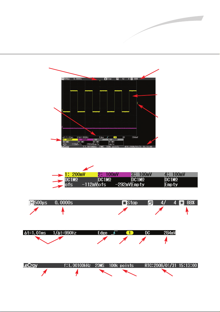
Understanding
Display Information
Trigger Position
Indicator
Color coded to the
triggered signal. Zero
delay is the center of
the grid.
Bottom Status Bar
Displays important
information about the
trigger and cursors.
Trace Descriptors
Displays Volts/Div,
Offset, and Coupling
of each channel and
math trace.
Top Status Bar
Displays important
information about the
acquisition mode and
timebase settings.
Grid Area
Portion of the display
where waveforms are
shown.
Trigger Level Indicator
Color coded to the
triggered signal.
Message Line
Provides information
about the sample rate,
memory length, and
frequency counter.
Trace Descriptors
Top Status Bar
Bottom Status Bar
Message Bar
Volts/Division
Channel Coupling
Channel Number
Offset
Time/Division Trigger Delay Trigger Status Sweep Counter
Intensity
Cursor Readouts
Trigger
Typ e
and Slope
Trigger
Source
Trigger
Coupling
Trigger
Level
Message Section
Any necessary
message will be
displayed here
Frequency
Counter
Displays frequency
of triggered signal
Sample Rate
Number
of Sample
Points
Clock Readout
Choose between
Real Time Clock and
Trigger Time Stamp
Page 3
3
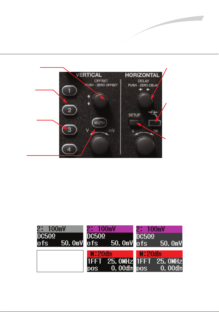
Vertical and
Horizontal Controls
Press Knob
to toggle between
zero delay and new
setting.
Light On
Indicates that the
vertical controls will
adjust that channel
(the active channel).
Light Off
Channel may or may
not be displayed,
vertical channels will
not adjust that
channel.
Math
Turns on the Math
trace and accesses
the Math menu.
Press Knob
to toggle between
zero delay and
new setting.
Quick Zoom
Press to turn on
zoom traces in
a separate grid.
Setup
Press to access
the Timebase
Setup menu.
If All Channel Lights are Off
Then the horizontal and vertical controls are “active” for a Math trace
or zoom trace. If the Zoom light is on then the horizontal controls will
adjust the zoom trace. If the Math light is on both the horizontal and
vertical controls will adjust the Math trace.
Math descriptor is
not displayed when
trace is turned off
Trace Off Trace On Trace Active
Page 4

Trigger Controls
4
Trigger Controls
Sets the trigger
level – push to
set to 50%.
Press to open the
trigger setup menu.
Triggers even if the
trigger conditions
are not met.
Triggers whenever
the trigger conditions
are met.
Cancels the
acquisition in
Auto or Normal;
press again to
trigger once
when the trigger
conditions are
met.
Trigger must be
stopped to enter
Replay mode.
Trigger Level
Indicator
Trigger Position
Indicator
Trigger Status
Trigger Type
and Slope
Trigger Source
Trigger Coupling
Trigger Level
Page 5

Using Cursors
5
Using Cursors
Use the Adjust knob
to position the cursors.
Press the knob in to
select between cursors
or to set the two cursors
to track together.
Press to turn cursors
on, toggle through
the cursor types, and
then turn the cursors
off. Choose between
Time, Amplitude,
Time & Amplitude,
and Value at Cursor.
When light is on the
Adjust knob controls
the cursor position.
Horizontal cursor information is located in the bottom
status bar directly below the waveform grid.
Vertical cursor information is located
in the trace descriptor.
When Time & Amplitude cursors
are used the readout is displayed
for both cursor types.
Page 6

6
Press the front panel Measure
button to access the Measure
menu and turn the measurement
parameters on. Press it again to
turn the parameters off.
Up to 4 measurements can be
displayed at a time, select between
measurement lines A, B, C, D.
Selects the source for your
measurement, it can be any of
the 4 channels or the Math trace.
Select between any of the 26
Automatic measurements.
Display or hide the minimum
and maximum statistics.
Measurement
Source
Measurement
Parameter
Last Value
Measured
Maximum
Measured
Value
Minimum
Measured
Value
Setting Up
Measurements
Page 7

7
Zoom Your Signals
Press the front panel Quick Zoom
button to zoom all displayed
traces including Math.
Original display before pressing the
Quick Zoom button.
After Quick Zoom is pressed the zoom
traces are displayed in a separate grid.
Use the delay and Time/Division
control to change the zoom factor
and portion of the waveform you
are zooming.
Page 8

8
Setting Up Math
Press the front panel Math button
to turn on the Math trace and
access the Math menu.
Selects the source for
the math trace, it can be
any of the 4 channels.
Select between the 4
available Math functions:
sum, difference, product,
ratio, FFT
Select FFT Window Type
When the Math light is on, use the
horizontal and vertical controls to adjust
the scale and position of the Math trace.
Setting Up Reference Waveforms
The Math trace appears on the display with Math
trace descriptor box.
Page 9

9
Saving Reference
Waveforms
Press the front panel REF
button to access the
Reference Waveform menu.
Turn the Reference
waveform on or off.
Select the source for the
waveform to save; select
from 4 channels and the
Math trace.
Recalls the oscilloscope
settings from when the
Reference waveform was
originally saved.
Saves the waveform to
Reference memory.
Reference Waveforms are displayed in white on
the waveform grid.
Select between 5 different
Reference waveforms.
Page 10

10
Documenting Results
WaveJet provides a front panel USB port for a quick and easy
way to save waveforms, screen captures, and setups.
Connect a USB memory device to the front panel USB port.
Press the front panel Print button to store a
screen capture to a USB memory device.
Set user preferences in the Utilities menu to
select file type, file name, and background
color.
Press the front panel Save/Recall button to access the
Save/Recall Menu.
In this menu save waveforms to USB memory in either
ASCII or binary formats, and save and recall setup files
from internal memory or from USB memory.
The Save/Recall menu is where the selection to recall the
Default Setup is located.
The rear panel USB port allows for printing
screen captures and can also be used for
remote control from a computer.
Page 11

11
Using Replay
Stop the trigger, then press the Intensity knob to
turn on Replay mode; the light will turn on.
Once in Replay, rotate the knob to look back at the
history of acquisitions to isolate runts, glitches, or
other abnormalities.
The display shows a runt pulse along
with a lot of variation in overshoot and
undershoot.
Activate Replay to view each acquisition
individually on the display.
Up to 1024 acquisitions can be viewed
with Replay.
Rotate the knob to scroll through each
acquisition.
Page 12

To offer comments or suggestions about the product,
please feel free to email the Product Manager at
WaveJet@lecroy.com
Thank You for Purchasing
a WaveJet Oscilloscope.
© 2009 by LeCroy Corporation. All rights reserved. Specifications, prices,
availability, and delivery subject to change without notice. Product or brand
names are trademarks or requested trademarks of their respective holders.
 Loading...