

Teledyne 3000ZA-3X User Manual
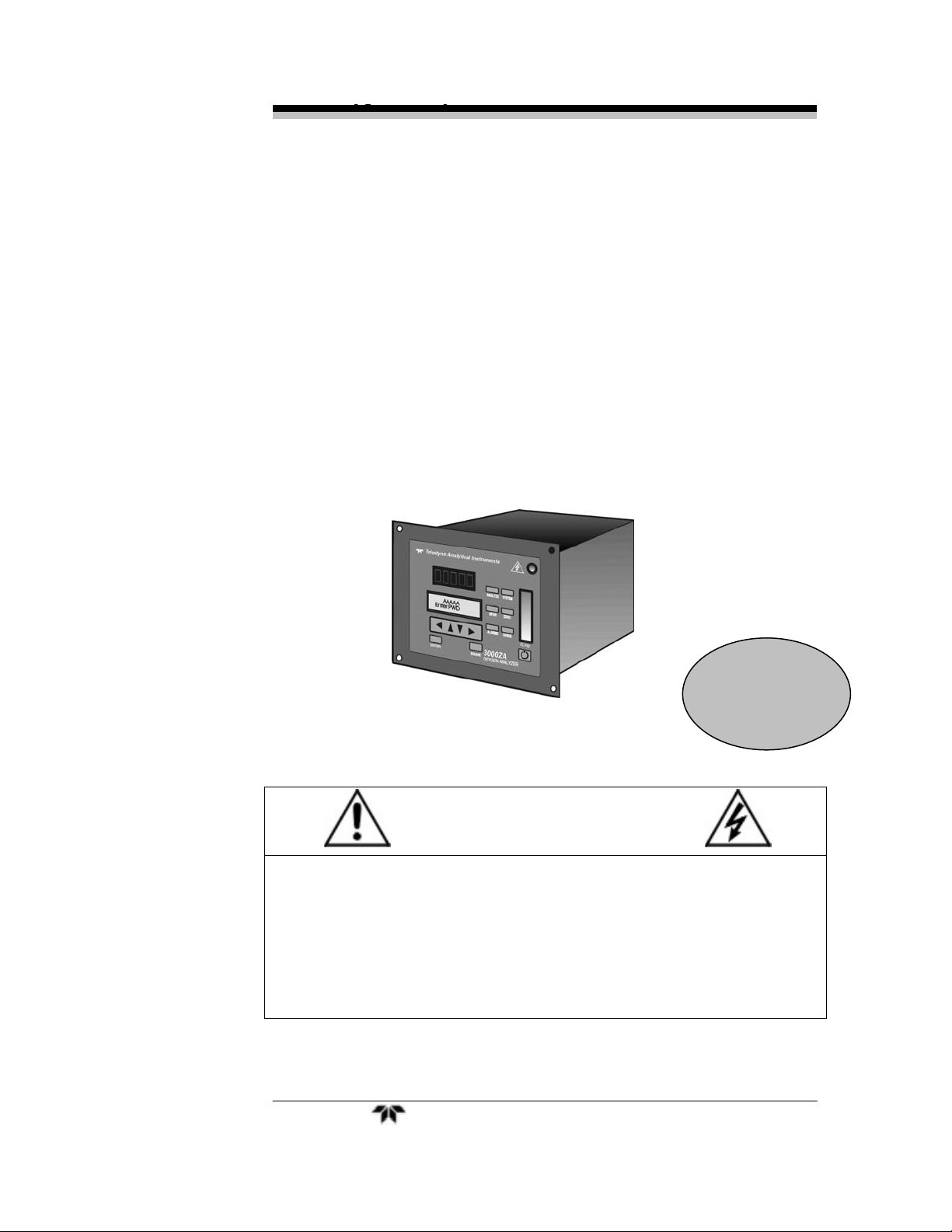
Trace Oxygen Analyzer
OPERATING INSTRUCTIONS FOR
MODEL 3000ZA-3X
Trace Oxygen Analyzer
P/N M77579
11/29/11
DANGER
Toxic gases and or flammable liquids may be present in this monitoring system.
Personal protective equipment may be required when servicing this instrument.
Hazardous voltages exist on certain components internally which may persist
for a time even after the power is turned off and disconnected.
Only authorized personnel should conduct maintenance and/or servicing.
Before conducting any maintenance or servicing, consult with authorized
supervisor/manager.
Teledyne Analytical Instruments i

3000ZA-3X
Copyright © 2011 Teledyne Analytical Instruments
All Rights Reserved. No part of this manual may be reproduced, transmitted, transcribed,
stored in a retrieval system, or translated into any other language or computer language in
whole or in part, in any form or by any means, whether it be electronic, mechanical,
magnetic, optical, manual, or otherwise, without the prior written consent of Teledyne
Analytical Instruments, 16830 Chestnut Street, City of Industry, CA 91749-1580.
Warranty
This equipment is sold subject to the mutual agreement that it is warranted by us free
from defects of material and of construction, and that our liability shall be limited to
replacing or repairing at our factory (without charge, except for transportation), or at
customer plant at our option, any material or construction in which defects become
apparent within one year from the date of shipment, except in cases where quotations
or acknowledgements provide for a shorter period. Components manufactured by
others bear the warranty of their manufacturer. This warranty does not cover defects
caused by wear, accident, misuse, neglect or repairs other than those performed by
Teledyne Analytical Instruments or an authorized service center. We assume no
liability for direct or indirect damages of any kind and the purchaser by the
acceptance of the equipment will assume all liability for any damage which may
result from its use or misuse.
We reserve the right to employ any suitable material in the manufacture of our
apparatus, and to make any alterations in the dimensions, shape or weight of any
parts, in so far as such alterations do not adversely affect our warranty.
Important Notice
This instrument provides measurement readings to its user, and serves as a tool by
which valuable data can be gathered. The information provided by the instrument may
assist the user in eliminating potential hazards caused by his process; however, it is
essential that all personnel involved in the use of the instrument or its interface, with the
process being measured, be properly trained in the process itself, as well as all
instrumentation related to it.
The safety of personnel is ultimately the responsibility of those who control process
conditions. While this instrument may be able to provide early warning of imminent
danger, it has no control over process conditions, and it can be misused. In particular,
any alarm or control systems installed must be tested and understood, both as to how
they operate and as to how they can be defeated. Any safeguards required such as
locks, labels, or redundancy, must be provided by the user or specifically requested of
Teledyne Analytical Instruments at the time the order is placed.
Therefore, the purchaser must be aware of the hazardous process conditions. The
purchaser is responsible for the training of personnel, for providing hazard warning
methods and instrumentation per the appropriate standards, and for ensuring that
hazard warning devices and instrumentation are maintained and operated properly.
Teledyne Analytical Instruments, the manufacturer of this instrument, cannot accept
responsibility for conditions beyond its knowledge and control. No statement
expressed or implied by this document or any information disseminated by the
manufacturer or its agents, is to be construed as a warranty of adequate safety control
under the user’s process conditions.
Teledyne Analytical Instruments ii

Trace Oxygen Analyzer
Specific Model Information
The instrument for which this manual was supplied may
incorporate one or more options not supplied in the standard instrument.
Commonly available options are listed below, with check boxes. Any
that are incorporated in the instrument for which this manual is supplied
are indicated by a check mark in the box.
Instrument Serial Number: _______________________
Options Included in the Instrument with the Above Serial Number:
3000ZA-C: In addition to all the standard features,
this model also has separate ports for
zero and span gases, and built-in
control valves. The internal valves are
entirely under the control of the
3000ZA electronics to automatically
switch between gases in
synchronization with the analyxer’s
operation.
3000ZA-Rack Mnt: The 19" Relay Rack Mount units are
available with either one or two 3000
series analyzers installed in a standard
19" panel and ready to mount in a
standard rack.
Teledyne Analytical Instruments iii
3000ZA-3X
Important Notice
Model 3000ZA complies with all of the requirements of the
Commonwealth of Europe (CE) for Radio Frequency Interference,
Electromagnetic Interference (RFI/EMI), and Low Voltage Directive
(LVD).
The following International Symbols are used throughout the
Instruction Manual. These symbols are visual indicators of important
and immediate warnings and when you must exercise CAUTION while
operating the instrument. See also the Safety Information on the next
page.
STAND-BY: Instrument is on Stand-by, but circuit is active
GROUND: Protective Earth
CAUTION: The operator needs to refer to the manual for
further information. Failure to do so may compromise the
safe operation of the equipment.
CAUTION: Risk of Electrical Shock
Teledyne Analytical Instruments iv
Trace Oxygen Analyzer
Safety Messages
Your safety and the safety of others is very important. We have
provided many important safety messages in this manual. Please read
these messages carefully.
A safety message alerts you to potential hazards that could hurt you
or others. Each safety message is associated with a safety alert symbol.
These symbols are found in the manual and inside the instrument. The
definition of these symbols is described below:
GENERAL WARNING/CAUTION: Refer to the
instructions for details on the specific danger. These cautions
warn of specific procedures which if not followed could
cause bodily Injury and/or damage the instrument.
No
Symbol
CAUTION: HOT SURFACE WARNING: This warning is
specific to heated components within the instrument. Failure
to heed the warning could result in serious burns to skin and
underlying tissue.
WARNING: ELECTRICAL SHOCK HAZARD: Dangerous
voltages appear within this instrument. This warning is
specific to an electrical hazard existing at or nearby the
component or procedure under discussion. Failure to heed
this warning could result in injury and/or death from
electrocution.
Technician Symbol: All operations marked with this
symbol are to be performed by qualified maintenance
personnel only.
NOTE: Additional information and comments regarding a
specific component or procedure are highlighted in the form
of a note.
Teledyne Analytical Instruments v
3000ZA-3X
CAUTION: THE ANALYZER SHOULD ONLY BE USED FOR THE
PURPOSE AND IN THE MANNER DESCRIBED IN
THIS MANUAL.
IF YOU USE THE ANALYZER IN A MANNER OTHER
THAN THAT FOR WHICH IT WAS INTENDED,
UNPREDICTABLE BEHAVIOR COULD RESULT
POSSIBLY ACCOMPANIED WITH HAZARDOUS
CONSEQUENCES.
This manual provides information designed to guide you through
the installation, calibration and operation of your new analyzer. Please
read this manual and keep it available.
Occasionally, some instruments are customized for a particular
application or features and/or options added per customer requests.
Please check the front of this manual for any additional information in
the form of an Addendum which discusses specific information,
procedures, cautions and warnings that may be peculiar to your
instrument.
Manuals do get lost. Additional manuals can be obtained from
Teledyne Analytical Instruments at the address given in the Appendix.
Some of our manuals are available in electronic form via the internet.
Please visit our website at: www.teledyne-ai.com.
Teledyne Analytical Instruments vi
Trace Oxygen Analyzer
This is a general purpose instrument designed for use in a non-hazardous
area. It is the customer's responsibility to ensure safety especially when
combustible gases are being analyzed since the potential of gas leaks
always exist.
The customer should ensure that the principles of operation of this
equipment is well understood by the user. Misuse of this product in any
manner, tampering with its components, or unauthorized substitution of
any component may adversely affect the safety of this instrument.
Since the use of this instrument is beyond the control of Teledyne
Analytical Instruments, no responsibility by Teledyne Analytical
Instruments, its affiliates, and agents for damage or injury from misuse
or neglect of this equipment is implied or assumed.
Teledyne Analytical Instruments vii

3000ZA-3X
Table of Contents
Safety Messages ............................................................. v
Introduction ..................................................................... 1
1.1 Overview 1
1.2 Typical Applications 1
1.3 Main Features of the Analyzer 1
1.4 Model Designations 2
1.5 Front Panel (Operator Interface) 3
1.6 Rear Panel (Equipment Interface) 5
Operational Theory ......................................................... 7
2.1 Introduction 7
2.2 ZrO2 Sensor 7
2.2.1 Principles of Operation 7
2.3 Sample System 8
2.4 Zirconium Oxide Sensor Application Notes 9
2.5 Electronics and Signal Processing 9
Installation ..................................................................... 13
3.1 Unpacking the Analyzer 13
3.2 Mounting the Analyzer 13
3.3 Rear Panel Connections 15
3.3.1 Gas Connections 15
3.3.2 Electrical Connections 17
3.3.2.1 Primary Input Power 17
3.3.2.2 50-Pin Equipment Interface Connector 18
3.3.2.3 RS-232 Port 24
3.4 Installing the Zirconium Oxide Sensors 26
Teledyne Analytical Instruments viii

Trace Oxygen Analyzer
3.5 Testing the System 26
Operation....................................................................... 27
4.1 Introduction 27
4.2 Using the Data Entry and Function Buttons 28
4.2.1 Style Conventions 28
4.2.2 Keys Description 28
4.2.2.1 Arrow Keys 29
4.2.2.2 ENTER 29
4.2.2.3 ESCAPE 29
4.2.2.4 Special Function Keys 30
4.3 Menu/Screen Structure 30
4.3.1 Analyze Screen 30
4.3.2 System Menu 30
4.3.3 Password routine 32
4.3.4 Logout Routine 33
4.3.5 Model Routine 33
4.3.6 Self-Test Routine 34
4.3.7 Filter Routine 34
4.3.8 Analog-Out Adjust Routine 34
4.3.9 Auto-Calibration Timer 36
4.3.10 Change Stream 36
4.4 Span Menu 36
4.4.1 Span Sensor 37
4.4.2 Span Value 37
4.4.3 Span Timer 37
4.4.4 Span Finish 38
4.4.5 Span Begin 38
4.5 Zero Menu 39
4.5.1 Zero Finish 39
4.5.2 Zero Value 39
4.5.3 Zero Begin 40
4.5.4 Zero Timer 40
Teledyne Analytical Instruments ix

3000ZA-3X
4.6 Alarms Menu 41
4.6.1 Alarm Active 41
4.6.2 Alarm Polarity 41
4.6.3 Alarm Failsafe 42
4.6.4 Alarm Latching 42
4.6.5 Alarm Setpoint 42
4.7 Range Menu 43
4.7.1 Range Select 43
4.7.2 Manual Range Select 44
4.7.3 Range Setpoints 44
Maintenance .................................................................. 45
5.1 Routine Maintenance 45
5.2 Sensor Replacement 45
5.2.1 Removing the Sensor 45
5.3 Fuse Replacement 47
5.4 System Self Diagnostic Test 48
5.5 Major Internal Components 49
5.6 Cleaning 50
5.7 Troubleshooting 50
Appendix ....................................................................... 53
A-1 Specifications 53
A-2 Recommended 2-Year Spare Parts List 55
A-3 Drawing List 56
A-4 19-inch Relay Rack Panel Mount 56
A.5 Application Notes 57
Teledyne Analytical Instruments x

Trace Oxygen Analyzer
List of Figures
Figure 1-1: Model 3000ZA Front Panel 3
Figure 1-2: Model 3000ZA Rear Panel 5
Figure 2-1: Model 3000ZA Sample System 8
Figure 2-2: Flow Diagram with Options 9
Figure 2-3: Component Location 11
Figure 2-4: Electronic Block Diagram 12
Figure 3-1: Front Panel of the Model 3000TA 14
Figure 3-2: Required Front Door Clearance 14
Figure 3-3: Rear Panel of the Model 3000ZA 15
Figure 3-4: Equipment Interface Connector Pin Arrangement 18
Figure 3-5: Remote Probe Connections 23
Figure 3-6: FET Series Resistance 24
Figure 4-1: Hierarchy of Available Functions 31
Figure 5-1: Sensor Block with Middle Sensor Installed 47
Figure 5-2: Removing Fuse Block from Housing 47
Figure 5-3: Installing Fuses 48
Figure 5-4: Rear Panel Removal 49
Figure A-1: Single and Dual 19" Rack Mounts 56
Teledyne Analytical Instruments xi

3000ZA-3X
List of Tables
Table 3-1: Analog Output Connections 19
Table 3-2: Alarm Relay Contact Pins 20
Table 3-3: Remote Calibration Connections 21
Table 3-4: Range ID Relay Connections 22
Table 3-5: Commands via RS-232 Input 25
Table 3-6: Required RS-232 Options 25
Table 5-1: Self-Test Result Display 48
Table 5-2: Troubleshooting 50
Teledyne Analytical Instruments xii

Trace Oxygen Analyzer Introduction
Introduction
1.1 Overview
The Teledyne Analytical Instruments Model 3000ZA Trace
Oxygen Analyzer is a versatile microprocessor-based instrument for
detecting oxygen at the parts-per-million (ppm) level in a variety of
gases. This manual covers the Model 3000ZA General Purpose flushpanel and/or rack-mount units with CE mark. These units are for indoor
use in a non-hazardous environment.
1.2 Typical Applications
A few typical applications of the Model 3000ZA are:
Monitoring inert gas blanketing
Air separation and liquefaction
Chemical reaction monitoring
Semiconductor manufacturing
Petrochemical process control
Quality assurance
Gas analysis certification.
1.3 Main Features of the Analyzer
The Model 3000ZA Trace Oxygen Analyzer is sophisticated yet
simple to use. The main features of the analyzer include:
A 2-line alphanumeric display screen, driven by
microprocessor electronics that continuously prompts
and informs the operator.
High resolution, accurate readings of oxygen content for
low ppm levels. Large, bright, meter readout.
Teledyne Analytical Instruments 1

Introduction 3000ZA-3X
Three Zirconium oxide sensors to provide higher range
of analysis flexibility. The analyzer can cover ranges as
low as 0-10 ppm or as high as 0-95%.
No reference gas required
Versatile analysis over a wide range of applications.
Microprocessor based electronics: 8-bit CMOS
microprocessor with 32 kB RAM and 128 kB ROM.
Three user definable output ranges (from 0-1 ppm
through 0-95%) allow best match to users process and
equipment.
Auto ranging allows analyzer to automatically select the
proper preset range for a given measurement. Manual
override allows the user to lock onto a specific range of
interest.
Two adjustable concentration alarms and a system
failure alarm.
Extensive self-diagnostic testing, at startup and on
demand, with continuous power-supply monitoring.
CE compliance
RS-232 serial digital port for use with a computer or
other digital communication device.
Four analog outputs: two for measurement (0–1 VDC
and isolated 4–20 mA DC) and two for range
identification.
Convenient and versatile, steel, flush-panel or rack-
mountable case with slide-out electronics drawer.
1.4 Model Designations
3000ZA: Standard model for sample under pressure
3000ZA-C: In addition to all the standard features, this
model also has separate ports for zero and
span gases, and built-in control valves. The
internal valves are entirely under the control
of the 3000ZA electronics to automatically
Teledyne Analytical Instruments 2
Trace Oxygen Analyzer Introduction
switch between gases in synchronization
with the analyzer’s operation.
3000ZA-M: This model has current output signals (4-20-
mA) for ppm range and range ID, in
addition to voltage outputs.
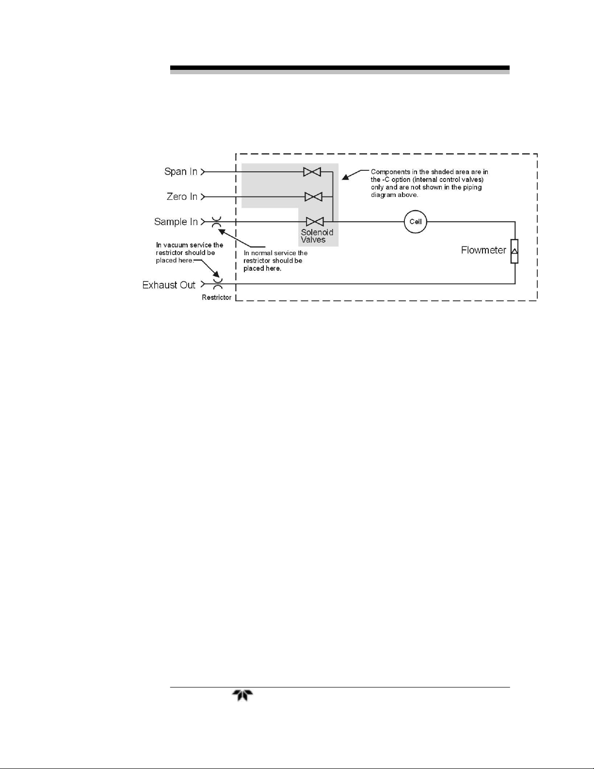
3000ZA-V: Gas flow through the cell block in this
model is driven by vacuum downstream
from the cell block instead of upstream
pressure. The internal restrictor is located
downstream from the cell block to support
this configuration. All other standard
features are present in this model.
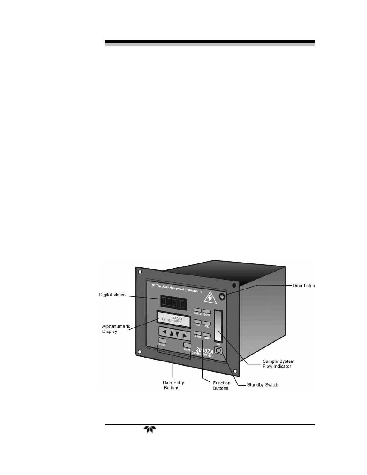
1.5 Front Panel (Operator Interface)
The standard 3000ZA is housed in a rugged metal case with all
controls and displays accessible from the front panel. See Figure 1-1.
The front panel has thirteen buttons for operating the analyzer, a digital
meter, an alphanumeric display, and a window for viewing the sample
flowmeter.
Figure 1-1: Model 3000ZA Front Panel
Teledyne Analytical Instruments 3

Introduction 3000ZA-3X
Function Keys:
Six touch-sensitive membrane switches are used to change the specific
function performed by the analyzer:
Analyze Perform analysis for oxygen content of a sample
gas.
System Perform system-related tasks (described in detail
in chapter 4, Operation.).
Span Span calibrate the analyzer.
Zero Zero calibrate the analyzer.
Alarms Set the alarm setpoints and attributes.
Range Set up the 3 user definable ranges for the
instrument.
Data Entry Keys:
Six touch-sensitive membrane switches are used to input data to the
instrument via the alphanumeric VFD display:
Left & Right Arrows Select between functions currently
displayed on the VFD screen.
Up & Down Arrows Increment or decrement values of
functions currently displayed.
Enter Advances VFD display to the next screen in a series
or returns to the Analyze screen if none remain.
Escape Backs VFD display to the previous screen in a series
or returns to the Analyze screen if none remain.
Digital Meter Display:
The meter display is a Light Emitting Diode (LED) device that produces
large, bright, 7-segment numbers that are legible in any lighting. It produces
a continuous readout from 0-250 ppm. It is accurate across all analysis
ranges without the discontinuity inherent in analog range switching.
Alphanumeric Interface Screen:
The VFD screen is an easy-to-use interface from operator to analyzer. It
displays values, options, and messages that give the operator immediate
feedback.
Flowmeter:
Monitors the flow of gas past the sensor. Readout is 0.2 to 2.4 standard
liters per minute (SLPM).
Teledyne Analytical Instruments 4
Trace Oxygen Analyzer Introduction
Standby Button :
The Standby turns off the display and outputs but circuitry is still
operating.
CAUTION: THE POWER CABLE MUST BE UNPLUGGED TO
FULLY DISCONNECT POWER FROM THE
INSTRUMENT. WHEN CHASSIS IS EXPOSED OR
WHEN ACCESS DOOR IS OPEN AND POWER CABLE
IS CONNECTED, USE EXTRA CARE TO AVOID
CONTACT WITH LIVE ELECTRICAL CIRCUITS.
Access Door:
For access to the ZrO2 sensors, the front panel swings open when the
latch in the upper right corner of the panel is pressed all the way in with
a narrow gauge tool. Accessing the main circuit board requires
unfastening rear panel screws and sliding the unit out of the case.
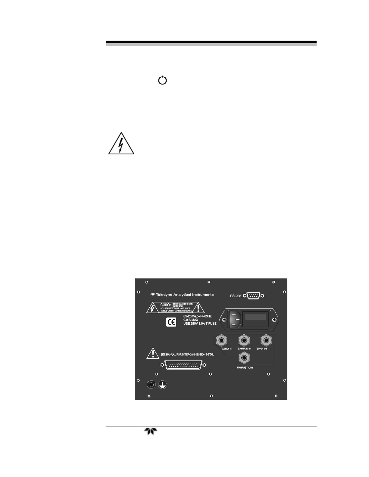
1.6 Rear Panel (Equipment Interface)
The rear panel, shown in Figure 1-2, contains the gas and electrical
connectors for external inlets and outlets. Some of those depicted are
optional and may not appear on your instrument. The connectors are
described briefly here and in detail in Chapter 3 Installation.
Figure 1-2: Model 3000ZA Rear Panel
Teledyne Analytical Instruments 5

Introduction 3000ZA-3X
Power Connection Universal AC power source.
Gas Inlet and Outlet One inlet (must be externally valved)
and one exhaust out. Three inlets
when option “C” is ordered.
9-Pin RS-232 Port Serial digital concentration signal
output and control input.
50-Pin Equipment Interface Port
Analog Outputs: 0–1 VDC oxygen concentration plus
0-1 VDC range ID
Alarm Connections: 2 concentration alarms and 1
system alarm.
Remote Valve: Used in the 3000ZA for controlling
external solenoid valves only.
Remote Span/Zero: Digital inputs allow external
control of analyzer calibration.
Calibration Contact: To notify external equipment that
instrument is being calibrated and readings are not
monitoring sample.
Range ID Contacts: Four separate, dedicated, range
relay contacts. Low, Medium, High, Cal.
Network I/O: Serial digital communications for local
network access. For future expansion. Not currently
implemented.
Optional
Calibration Gas Ports: Separate fittings for zero, span, and
sample gas input, internal valves
for automatic gas switching.
Current Signal Output: Additional isolated 4–20 mA
DC plus 4–20 mA DC range ID.
Note: If you require highly accurate Auto-Cal timing, use external
Auto-Cal control where possible. The internal clock in the
Model 3000ZA is accurate to 2-3 %. Accordingly, internally
scheduled calibrations can vary 2-3 % per day.
Teledyne Analytical Instruments 6

Trace Oxygen Analyzer Operational Theory
Operational Theory
2.1 Introduction
The analyzer is composed of three subsystems:
1. Three Zirconium Oxide (ZrO
specific range of analysis: Low range sensor of 0-200
ppm, medium range sensor of 0-2 %, and high range
sensor of 0-95%.
2. Sample System
3. Electronic Signal Processing, Display and Control
The sample system is designed to accept the sample gas and
transport it through the analyzer without contaminating or altering the
sample prior to analysis. The ZrO2 sensor is a device that translates the
amount of oxygen present in the sample into an electrical current. The
electronic signal processing, display and control subsystem simplifies
operation of the analyzer and accurately processes the sampled data. The
microprocessor controls all signal processing, input/output and display
functions for the analyzer.
) Sensors. Each one has a
2
2.2 ZrO2 Sensor
2.2.1 Principles of Operation
Teledyne’s zirconium oxide sensor is a miniature solid state sensor.
It uses a stabilized zirconia disc as an electrolyte with a sensing
electrode (the cathode) and a counter electrode (the anode) on each side
of the disc. The zirconia is heated to a temperature of about 500°C via a
built-in heater. By applying a suitable reference voltage (approximately
0.75 volt) across the cathode and anode, the heated zirconia acts as an
electrolyte which is capable of moving oxygen ions within its crystalline
structure. This allows for the reduction of oxygen molecules reaching
the cathode and the generation of a current equivalent to the parts per
million oxygen in the sample gas.
Teledyne Analytical Instruments 7
Operational Theory 3000ZA-3X
One of the three sensors has been modified (0-200 ppm range) to
sense low levels of oxygen—less than 1 ppm and generate a current
proportional to the concentration. The sensor is designed for long term
stability and an operating life of 5 years.
2.3 Sample System
The sample system delivers gases to the ZrO2 sensors, located on
the cell block, from the analyzer rear panel inlet. Depending on the
mode of operation either sample or calibration gas is delivered.
The Model 3000ZA sample system is designed and fabricated to
ensure that the oxygen concentration of the gas is not altered as it travels
through the sample system.
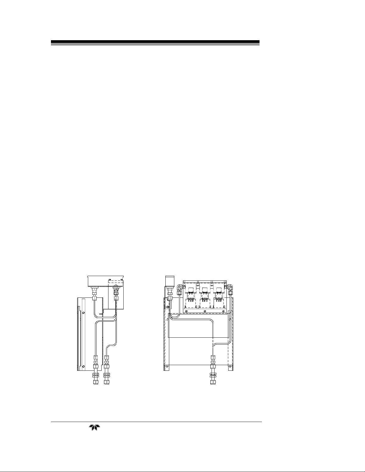
The sample system for the standard instrument incorporates
compression tube fittings for sample inlet and 1/4” outlet tube
connections at the rear panel. The sample or calibration gas that flows
through the system is monitored by a flowmeter downstream from the
cell. Figure 2-1 shows the piping layout for the standard model.
Figure 2-2 shows the flow diagram for sampling systems used for
the three configurations offered as options for this instrument. In the
standard instrument, calibration gases can be connected directly to the
Sample In port by teeing to the port with appropriate valves.
Figure 2-1: Model 3000ZA-3X Sample System
Teledyne Analytical Instruments 8
Trace Oxygen Analyzer Operational Theory
Figure 2-2: Flow Diagram with Options
2.4 Zirconium Oxide Sensor Application Notes
The following sample gases require conditioning prior to entering
the sensors:
Flammable gases such as methane, alcohol and carbon
monoxide may cause a measurement error. They must be
filtered from the sample gas before entering the cell.
Gases containing halogen atoms (F, Cl, Br, etc.) such as
Freon, must be filtered before entering the cell. The sensor
will be damaged by the decomposition of Freon.
Gases containing SOx, H2S, silicone vapor and adhesives
must not enter the sensor. These components adversely affect
the performance of the sensor.
Dust and oil should be filtered from the sample gas.
Water vapor in contact with the sensor will damage the
sensor. Use a moisture trap or filter to remove any water
vapor in the sample.
2.5 Electronics and Signal Processing
The Model 3000ZA Trace Oxygen Analyzer uses an 8031
microcontroller with 32 kB of RAM and 128 kB of ROM to control all
signal processing, input/output, and display functions for the analyzer.
Teledyne Analytical Instruments 9

Operational Theory 3000ZA-3X
System power is supplied from a universal power supply module designed
to be compatible with any international power source. Figure 2-3 shows
the location of the power supply and the main electronic PC boards.
The signal processing electronics including the microprocessor,
analog to digital, and digital to analog converters are located on the
motherboard at the bottom of the case. The preamplifier board is
mounted on top of the motherboard as shown in the figure. These boards
are accessible after removing the back panel. Figure 2-4 is a block
diagram of the analyzer electronics.
In the presence of oxygen the zirconia sensor generates a current. A
current to voltage amplifier converts this current to a voltage, which is
amplified in the second stage amplifier. The output from the second
stage amplifier is sent to an 18 bit analog to digital converter controlled
by the microprocessor. In the block diagram only one sensor is shown,
but in reality there are three separate amplifier circuits for each sensor.
The output of each sensor is then multiplexed to the analog to digital
converter.
The high operating temperature of the ZrO
sensor is required for
2
proper operation of the sensor. The amplifier PCB contains a circuit that
drives the heater embedded in the sensor. The voltage across the heater
rises slowly to avoid damaging the heater/sensor assembly. After a few
minutes, the sensor will be at the proper operating temperature.
The digital concentration signal along with input from the control
panel is processed by the microprocessor, and appropriate control
signals are directed to the display, alarms and communications port. The
same digital information is also sent to a 12 bit digital to analog
converter that produces the 4-20 mA dc and the 0-1 VDC analog
concentration signal outputs, and the analog range ID outputs.
Signals from the power supply are also monitored, and through the
microprocessor, the system failure alarm is activated if a malfunction is
detected.
Teledyne Analytical Instruments 10
 Loading...