

Teledyne 3000TA-XL-EU User Manual
Trace Oxygen Analyzer
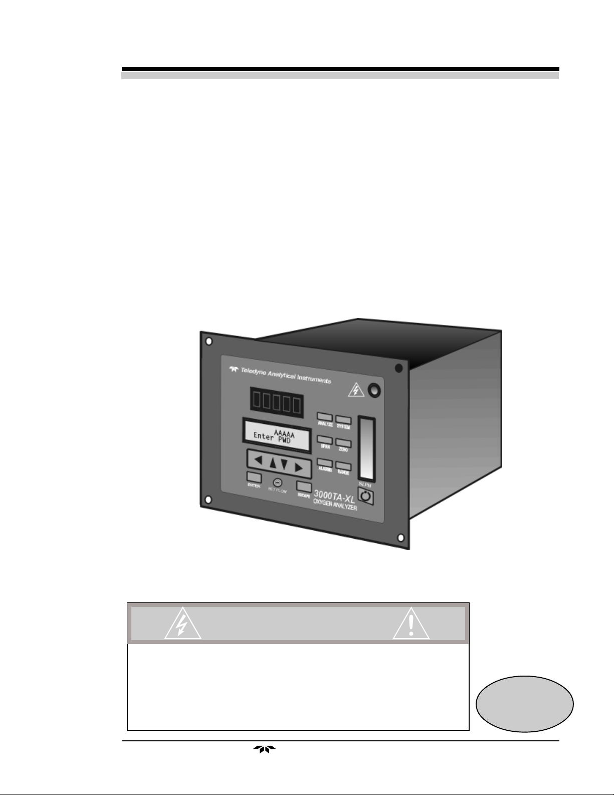
OPERATING INSTRUCTIONS FOR
Model 3000TA-XL-EU
Trace Oxygen Analyzer
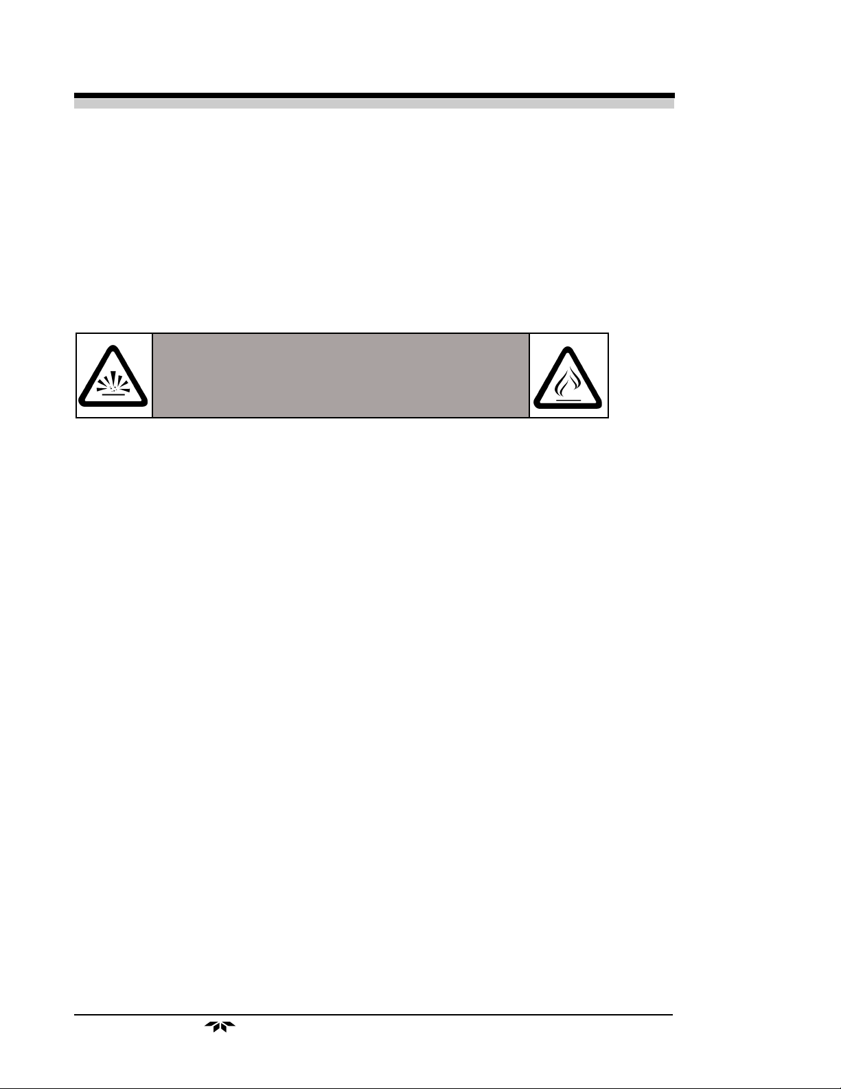
DANGER
HIGHLY TOXIC AND OR FLAMMABLE LIQUIDS OR GASES MAY BE PRESENT IN THIS MONITORING
SYSTEM.
PERSONAL PROTECTIVE EQUIPMENT MAY BE REQUIRED WHEN SERVICING THIS SYSTEM.
HAZARDOUS VOLTAGES EXIST ON CERTAIN COMPONENTS INTERNALLY WHICH MAY PERSIST
FOR A TIME EVEN AFTER THE POWER IS TURNED OFF AND DISCONNECTED.
ONLY AUTHORIZED PERSONNEL SHOULD CONDUCT MAINTENANCE AND/OR SERVICING. BEFORE
CONDUCTING ANY MAINTENANCE OR SERVICING CONSULT WITH AUTHORIZED SUPERVISOR/
MANAGER.
Teledyne Analytical Instruments
P/N M69603
11/24/04
ECO # 03-0126
i

Model 3000TA-XL-EU
Copyright © 1999 Teledyne Analytical Instruments
All Rights Reserved. No part of this manual may be reproduced, transmitted, transcribed, stored in a retrieval system, or translated into any other language or computer
language in whole or in part, in any form or by any means, whether it be electronic,
mechanical, magnetic, optical, manual, or otherwise, without the prior written consent of
Teledyne Analytical Instruments, 16830 Chestnut Street, City of Industry, CA 91749-1580.
Warranty
This equipment is sold subject to the mutual agreement that it is warranted by us free
from defects of material and of construction, and that our liability shall be limited to
replacing or repairing at our factory (without charge, except for transportation), or at
customer plant at our option, any material or construction in which defects become
apparent within one year from the date of shipment, except in cases where quotations or
acknowledgements provide for a shorter period. Components manufactured by others bear
the warranty of their manufacturer. This warranty does not cover defects caused by wear,
accident, misuse, neglect or repairs other than those performed by Teledyne or an authorized service center. We assume no liability for direct or indirect damages of any kind and
the purchaser by the acceptance of the equipment will assume all liability for any damage
which may result from its use or misuse.
We reserve the right to employ any suitable material in the manufacture of our
apparatus, and to make any alterations in the dimensions, shape or weight of any parts, in
so far as such alterations do not adversely affect our warranty.
Important Notice
This instrument provides measurement readings to its user, and serves as a tool by
which valuable data can be gathered. The information provided by the instrument may
assist the user in eliminating potential hazards caused by his process; however, it is
essential that all personnel involved in the use of the instrument or its interface, with the
process being measured, be properly trained in the process itself, as well as all instrumentation related to it.
The safety of personnel is ultimately the responsibility of those who control process
conditions. While this instrument may be able to provide early warning of imminent danger,
it has no control over process conditions, and it can be misused. In particular, any alarm or
control systems installed must be tested and understood, both as to how they operate and
as to how they can be defeated. Any safeguards required such as locks, labels, or redundancy, must be provided by the user or specifically requested of Teledyne at the time the
order is placed.
Therefore, the purchaser must be aware of the hazardous process conditions. The
purchaser is responsible for the training of personnel, for providing hazard warning
methods and instrumentation per the appropriate standards, and for ensuring that hazard
warning devices and instrumentation are maintained and operated properly.
Teledyne Analytical Instruments, the manufacturer of this instrument, cannot
accept responsibility for conditions beyond its knowledge and control. No statement
expressed or implied by this document or any information disseminated by the manufacturer or its agents, is to be construed as a warranty of adequate safety control under the
user’s process conditions.
ii
Teledyne Analytical Instruments

Trace Oxygen Analyzer
Specific Model Information
The instrument for which this manual was supplied may incorporate one or
more options not supplied in the standard instrument. Commonly available
options are listed below, with check boxes. Any that are incorporated in the
instrument for which this manual is supplied are indicated by a check mark in the
box.
Instrument Serial Number: _______________________
Options Included in the Instrument with the Above Serial Number:
3000TA-XL-VS: Instrument configured for Vacuum Service
3000TA-XL-CV: Instrument with calibration valves
19" Rack Mnt: The 19" Relay Rack Mount units are available with
either one or two 3000TA-XL series analyzers installed
in a standard 19" panel and ready to mount in a
standard rack.
Teledyne Analytical Instruments
iii
Model 3000TA-XL-EU
Model 3000TA-XL-EU complies with all of the requirements of
the Commonwealth of Europe (CE) for Radio Frequency Interference, Electromagnetic Interference (RFI/EMI), and Low Voltage
Directive (LVD).
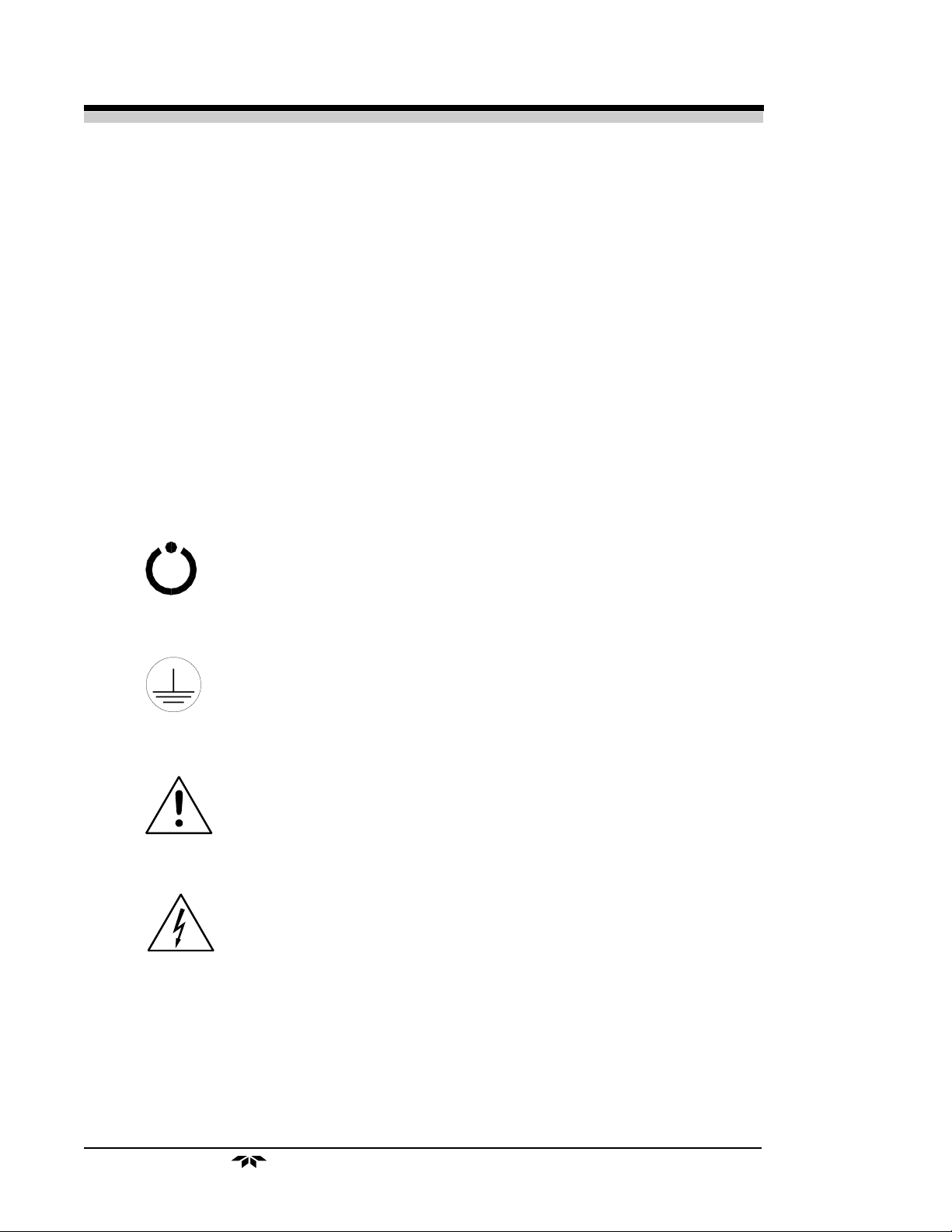
The following International Symbols are used throughout the Instruction Manual for your visual and immediate warnings and when you
have to attend CAUTION while operating the instrument:
STAND-BY, Instrument is on Stand-by,
but circuit is active
GROUND
Protective Earth
CAUTION, The operator needs to refer to the manual
for further information. Failure to do so may
compromise the safe operation of the equipment.
CAUTION, Risk of Electric Shock
iv
Teledyne Analytical Instruments

Trace Oxygen Analyzer
Table of Contents
1 Introduction
1.1 Overview ........................................................................ 1-1
1.2 Typical Applications ....................................................... 1-1
1.3 Main Features of the Analyzer ....................................... 1-1
1.4 Model Designations ....................................................... 1-2
1.5 Front Panel (Operator Interface) ..................................... 1-3
1.6 Rear Panel (Equipment Interface) .................................. 1-5
2 Operational Theory
2.1 Introduction .................................................................... 2-1
2.2 Micro-Fuel Cell Sensor .................................................. 2-1
2.2.1 Principles of Operation ............................................ 2-1
2.2.2 Anatomy of a Micro-Fuel Cell .................................. 2-2
2.2.3 Electrochemical Reactions ...................................... 2-3
2.2.4 The Effect of Pressure.............................................. 2-4
2.2.5 Calibration Characteristics ...................................... 2-4
2.3 Sample System .............................................................. 2-5
2.4 Electronics and Signal Processing ................................ 2-8
3 Installation
3.1 Unpacking the Analyzer ................................................. 3-1
3.2 Mounting the Analyzer ................................................... 3-1
3.3 Rear Panel Connections ................................................ 3-2
3.3.1 Gas Connections ................................................... 3-3
3.3.2 Electrical Connections ........................................... 3-4
3.3.2.1 Primary Input Power....................................... 3-4
3.3.2.2 50-Pin Equipment Interface Connector .......... 3-4
3.3.2.3 RS-232 Port ................................................... 3-9
3.4 Installing the Micro-Fuel Cell ......................................... 3-11
3.5 Testing the System ......................................................... 3-11
4 Operation
4.1 Introduction .................................................................... 4-1
4.2 Using the Data Entry and Function Buttons ................... 4-2
4.3 The System Function ..................................................... 4-3
4.3.1 Tracking the O2 Readings during CAl & Alarm ....... 4-4
4.3.2 Setting up an Auto-Cal ........................................... 4-5
4.3.3 Password Protection .............................................. 4-6
4.3.3.1 Entering the Password ................................... 4-7
Teledyne Analytical Instruments
v

Model 3000TA-XL-EU
4.3.3.2 Installing or Changing the Password ............. 4-8
4.3.4 Logout .................................................................... 4-9
4.3.5 System Self-Diagnostic Test .................................. 4-9
4.3.6 Version Screen ...................................................... 4-10
4.4 Calibration of the Analyzer ............................................. 4-11
4.4.1 Zero Cal ................................................................. 4-11
4.4.1.1 Auto Mode Zeroing ........................................ 4-12
4.4.1.2 Manual Mode Zeroing .................................... 4-12
4.4.1.3 Cell Failure .................................................... 4-13
4.4.2 Span Cal ................................................................ 4-14
4.4.2.1 Auto Mode Spanning ..................................... 4-14
4.4.2.2 Manual Mode Spanning................................. 4-15
4.4.3 Span Failure .......................................................... 4-16
4.5 Switching of Sample Streams ........................................ 4-16
4.5.1 Special notes on hydrogen gas stream .................. 4-17
4.6 The Alarms Function ...................................................... 4-17
4.7 The Range Function ...................................................... 4-19
4.7.1 Setting the Analog Output Ranges......................... 4-20
4.7.2 Fixed Range Analysis............................................ 4-20
4.8 The Analyze Function .................................................... 4-21
4.9 Signal Output ................................................................. 4-21
Maintenance
5.1 Routine Maintenance ..................................................... 5-1
5.2 Cell Replacement .......................................................... 5-1
5.2.1 Storing and Handling Replacement Cells ............... 5-1
5.2.2 When to Replace a Cell ........................................... 5-2
5.2.3 Removing the Micro-Fuel Cell ................................. 5-2
5.2.4 Installing a New Micro-Fuel Cell .............................. 5-4
5.2.5 Cell Warranty ........................................................... 5-4
5.3 Fuse Replacement......................................................... 5-5
5.4 System Self Diagnostic Test ........................................... 5-5
5.5 Major Internal Components ............................................ 5-6
5.6 Cleaning ........................................................................ 5-7
5.7 Troubleshooting ............................................................. 5-8
Appendix
A-1 Model 3000TA-XL Specifications ................................... A-1
A-2 Recommended 2-Year Spare Parts List ......................... A-3
A-3 Drawing List ................................................................... A-4
A-4 19-Inch Relay Rack Panel Mount................................... A-4
A-5 Application Notes on Pressures and Flow ..................... A-5
vi
Teledyne Analytical Instruments

Trace Oxygen Analyzer
Appendix
A-6 Material Safety Data Sheet..................................................A-8
A-7 Installing and Replacing Micro Fuel Cell.........................A-12
Teledyne Analytical Instruments
vii
Model 3000TA-XL-EU
DANGER
COMBUSTIBLE GAS USAGE WARNING
This is a general purpose instrument designed for use in a
nonhazardous area. It is the customer's responsibility to ensure
safety especially when combustible gases are being analyzed
since the potential of gas leaks always exist.
The customer should ensure that the principles of operation of
this equipment is well understood by the user. Misuse of this
product in any manner, tampering with its components, or unauthorized substitution of any component may adversely affect
the safety of this instrument.
Since the use of this instrument is beyond the control of
Teledyne, no responsibility by Teledyne, its affiliates, and agents
for damage or injury from misuse or neglect of this equipment is
implied or assumed.
viii
Teledyne Analytical Instruments

Trace Oxygen Analyzer Introduction 1
Introduction
1.1 Overview
The Teledyne Analytical Instruments Model 3000TA-XL Trace Oxygen Analyzer is a versatile microprocessor-based instrument for detecting
oxygen at the parts-per-million (ppm) level in a variety of gases. This manual
covers the Model 3000TA-XL General Purpose flush-panel and/or rackmount units only. These units are for indoor use in a nonhazardous environment.
1.2 Typical Applications
A few typical applications of the Model 3000TA-XL are:
• Monitoring inert gas blanketing
• Air separation and liquefaction
• Chemical reaction monitoring
• Semiconductor manufacturing
• Petrochemical process control
• Quality assurance
• Gas analysis certification.
1.3 Main Features of the Analyzer
The Model 3000TA-XL Trace Oxygen Analyzer is sophisticated yet
simple to use. The main features of the analyzer include:
• A 2-line alphanumeric vacuum fluorescent display (VFD) screen,
driven by microprocessor electronics, that continuously prompts
and informs the operator.
• High resolution, accurate readings of oxygen content from low
ppm levels through 25%. Large, bright, meter readout.
• Stainless steel cell block.
Teledyne Analytical Instruments
1-1

1 Introduction Model 3000TA-XL-EU
• Advanced Micro-Fuel Cell, designed for trace analysis, has a 0-1
ppm low range with less than a 0.2 ppm offset and six months
warranty and an expected lifetime of one year.
• Versatile analysis over a wide range of applications.
• Microprocessor based electronics: 8-bit CMOS microprocessor
with 32 kB RAM and 128 kB ROM.
• Three user definable output ranges (from 0-1 ppm through 0250,000 ppm) allow best match to users process and equipment.
• Air-calibration range for spanning at 20.9 % (209,000 ppm)
available.
• Auto Ranging allows analyzer to automatically select the proper
preset range for a given measurement. Manual override allows
the user to lock onto a specific range of interest.
• Two adjustable concentration alarms and a system failure alarm.
• Extensive self-diagnostic testing, at startup and on demand, with
continuous power-supply monitoring.
• Two way RFI protection.
• RS-232 serial digital port for use with a computer or other digital
communication device.
• Four analog outputs: two for measurement (0–1 V dc and
Isolated 4–20 mA dc) and two for range identification.
• Convenient and versatile, steel, flush-panel or rack-mountable
case with slide-out electronics drawer.
1.4 Model Designations
3000TA-XL: Standard model for sample under pressure
3000TA-XL-VS: Instrument configured for Vacuum Service
3000TA-XL-CV: Instrument with calibration valves
1-2
Teledyne Analytical Instruments
Trace Oxygen Analyzer Introduction 1
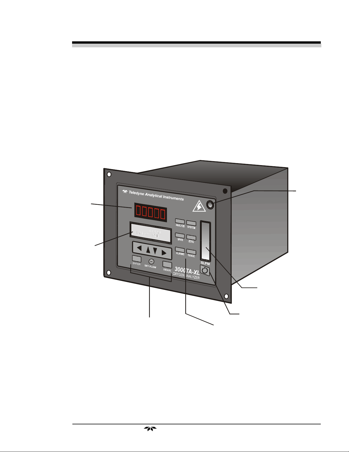
1.5 Front Panel (Operator Interface)
The standard 3000TA-XL is housed in a rugged metal case with all
controls and displays accessible from the front panel. See Figure 1-1. The
front panel has thirteen buttons for operating the analyzer, a digital meter, an
alphanumeric display, and a window for viewing the sample flowmeter.
Function Keys: Six touch-sensitive membrane switches are used to
change the specific function performed by the analyzer:
Door Latch
Digital Meter
Alphanumeric
Di spl ay
Sample System
Flow Indicator
Standby Switch
Data Entry Buttons
Figure 1-1: Model 3000TA-XL Front Panel
Function Buttons
• Analyze Perform analysis for oxygen content of a sample gas.
• System Perform system-related tasks (described in detail in
chapter 4, Operation.).
• Span Span calibrate the analyzer.
• Zero Zero calibrate the analyzer.
Teledyne Analytical Instruments
1-3

1 Introduction Model 3000TA-XL-EU
• Alarms Set the alarm setpoints and attributes.
• Range Set up the 3 user definable ranges for the instrument.
Data Entry Keys: Six touch-sensitive membrane switches are used to
input data to the instrument via the alphanumeric VFD display:
• Left & Right Arrows Select between functions currently
displayed on the VFD screen.
• Up & Down Arrows Increment or decrement values of
functions currently displayed.
• Enter Moves VFD display on to the next screen in a series. If
none remains, returns to the Analyze screen.
• Escape Moves VFD display back to the previous screen in a
series. If none remains, returns to the Analyze screen.
Digital Meter Display: The meter display is a Light Emitting Diode
(LED) device that produces large, bright, 7-segment numbers that are legible
in any lighting. It produces a continuous readout from 0-10,000 ppm and
then switches to a continuous percent readout from 1-25%. It is accurate
across all analysis ranges without the discontinuity inherent in analog range
switching.
Alphanumeric Interface Screen: The VFD screen is an easy-to-use
interface from operator to analyzer. It displays values, options, and messages
that give the operator immediate feedback.
NeedleValve: To adjust flow of gas sample
Flowmeter: Monitors the flow of gas past the sensor. Readout is 0.2 to
2.4 standard liters per minute (SLPM) of nitrogen
Standby Button: The Standby turns off the display and outputs,
but circuitry is still operating.
CAUTION: The power cable must be unplugged to fully
disconnect power from the instrument. When
chassis is exposed or when access door is open
and power cable is connected, use extra care to
avoid contact with live electrical circuits .
Access Door: For access to the Micro-Fuel Cell, the front panel
swings open when the latch in the upper right corner of the panel is pressed
1-4
Teledyne Analytical Instruments
Trace Oxygen Analyzer Introduction 1
all the way in with a narrow gauge tool. Accessing the main circuit board
requires unfastening rear panel screws and sliding the unit out of the case.
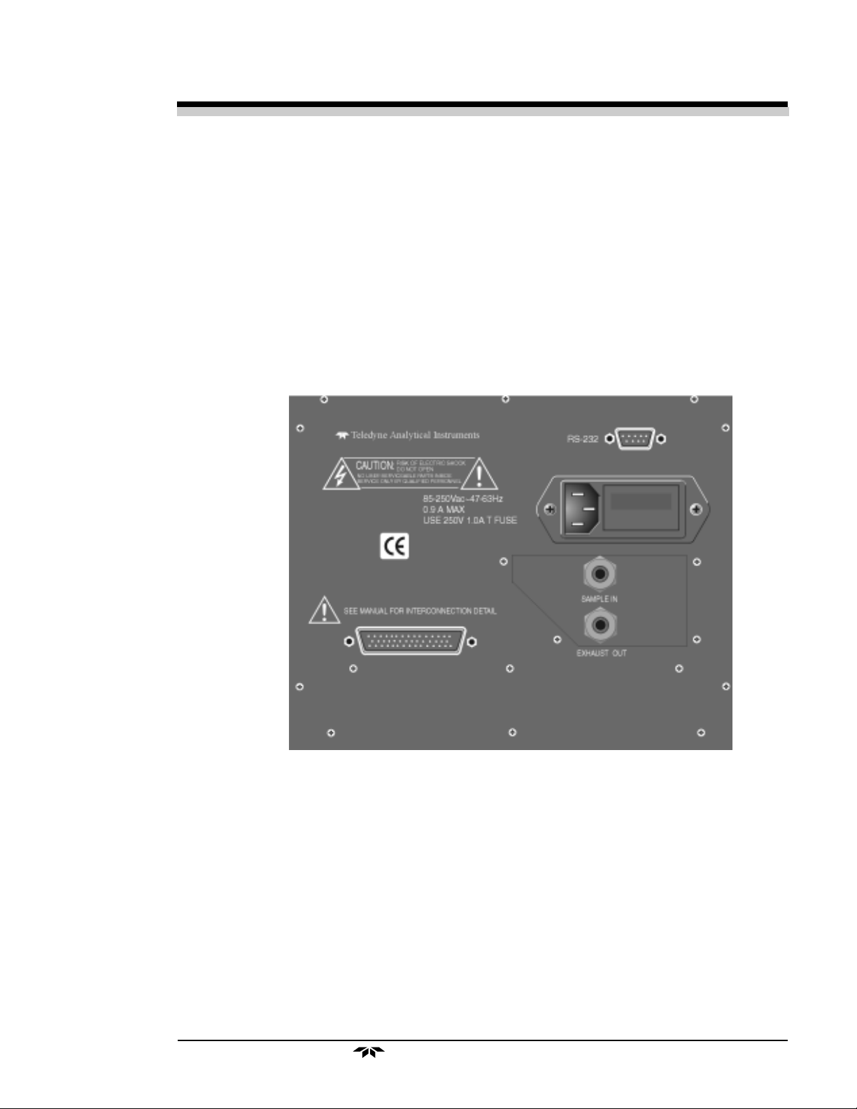
1.6 Rear Panel (Equipment Interface)
The rear panel, shown in Figure 1-2, contains the gas and electrical
connectors for external inlets and outlets. Some of those depicted are optional and may not appear on your instrument. The connectors are described
briefly here and in detail in chapter 3 Installation.
Figure 1-2: Model 3000TA-XL Rear Panel
• Power Connection Universal AC power source.
• Gas Inlet and Outlet One inlet and one exhaust out.
• Analog Outputs 0–1 V dc oxygen concentration plus 0-1
V dc range ID, and isolated 4–20 mA dc
oxygen concentration plus 4-20 mA dc
range ID.
• Alarm Connections 2 concentration alarms and 1 system
alarm.
Teledyne Analytical Instruments
1-5

1 Introduction Model 3000TA-XL-EU
• RS-232 Port Serial digital concentration signal output
and control input.
• Remote Probe Used in the 3000TA-XL for controlling
external solenoid valves only.
• Remote Span/Zero Digital inputs allow external control of
analyzer calibration.
• Calibration Contact To notify external equipment that
instrument is being calibrated and
readings are not monitoring sample.
• Range ID Contacts Four separate, dedicated, range relay
contacts. Low, Medium, High, Cal.
• Network I/O Serial digital communications for local
network access. For future expansion.
Not implemented at this printing.
Note: If you require highly accurate Auto-Cal timing, use external
Auto-Cal control where possible. The internal clock in the
Model 3000TA-XL is accurate to 2-3 %. Accordingly, internally
scheduled calibrations can vary 2-3 % per day.
1-6
Teledyne Analytical Instruments

Trace Oxygen Analyzer Operational Theory 2
Operational Theory
2.1 Introduction
The analyzer is composed of three subsystems:
1. Micro-Fuel Cell Sensor
2. Sample System
3. Electronic Signal Processing, Display and Control
The sample system is designed to accept the sample gas and transport it
through the analyzer without contaminating or altering the sample prior to
analysis. The Micro-Fuel Cell is an electrochemical galvanic device that
translates the amount of oxygen present in the sample into an electrical
current. The electronic signal processing, display and control subsystem
simplifies operation of the analyzer and accurately processes the sampled
data. The microprocessor controls all signal processing, input/output and
display functions for the analyzer.
2.2 Micro-Fuel Cell Sensor
2.2.1 Principles of Operation
The oxygen sensor used in the Model 3000TA-XL series is a MicroFuel Cell, Model B-2CXL designed and manufactured by Analytical Instruments. It is a sealed plastic disposable electrochemical transducer.
The active components of the Micro-Fuel Cell are a cathode, an anode,
and the aqueous KOH electrolyte in which they are immersed. The cell
converts the energy from a chemical reaction into an electrical current in an
external electrical circuit. Its action is similar to that of a battery.
There is, however, an important difference in the operation of a battery
as compared to the Micro-Fuel Cell: In the battery, all reactants are stored
within the cell, whereas in the Micro-Fuel Cell, one of the reactants (oxygen)
Teledyne Analytical Instruments
2-1
2 Operational Theory Model 3000TA-XL-EU
comes from outside the device as a constituent of the sample gas being
analyzed. The Micro-Fuel Cell is therefore a hybrid between a battery and a
true fuel cell. (All of the reactants are stored externally in a true fuel cell.)
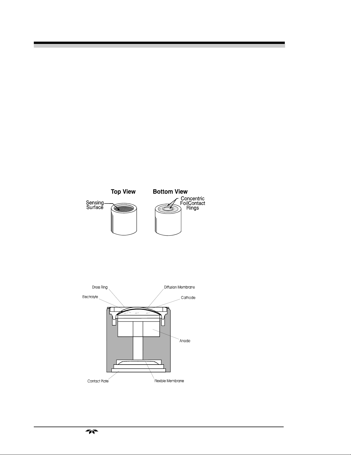
2.2.2 Anatomy of a Micro-Fuel Cell
The Micro-Fuel Cell is a cylinder only 1¼ inches in diameter and 1¼
inches thick. It is made of an extremely inert plastic, which can be placed
confidently in practically any environment or sample stream. It is effectively
sealed, although one end is permeable to oxygen in the sample gas. The
other end of the cell is a contact plate consisting of two concentric foil rings.
The rings mate with spring-loaded contacts in the sensor block assembly and
provide the electrical connection to the rest of the analyzer. Figure 2-1
illustrates the external features.
Figure 2-1: Micro-Fuel Cell
Refer to Figure 2-2, Cross Section of a Micro-Fuel Cell, which illustrates the following internal description.
Figure 2-2. Cross Section of a Micro-Fuel Cell (not to scale)
At the top end of the cell is a diffusion membrane of Teflon, whose
thickness is very accurately controlled. Beneath the diffusion membrane lies
2-2
Teledyne Analytical Instruments

Trace Oxygen Analyzer Operational Theory 2
the oxygen sensing element—the cathode—with a surface area almost 4 cm2.
The cathode has many perforations to ensure sufficient wetting of the upper
surface with electrolyte, and it is plated with an inert metal.
The anode structure is below the cathode. It is made of lead and has a
proprietary design which is meant to maximize the amount of metal available
for chemical reaction.
At the rear of the cell, just below the anode structure, is a flexible
membrane designed to accommodate the internal volume changes that occur
throughout the life of the cell. This flexibility assures that the sensing membrane remains in its proper position, keeping the electrical output constant.
The entire space between the diffusion membrane, above the cathode,
and the flexible rear membrane, beneath the anode, is filled with electrolyte.
Cathode and anode are submerged in this common pool. They each have a
conductor connecting them to one of the external contact rings on the contact
plate, which is on the bottom of the cell.
2.2.3 Electrochemical Reactions
The sample gas diffuses through the Teflon membrane. Any oxygen in
the sample gas is reduced on the surface of the cathode by the following
HALF REACTION:
O2 + 2H2O + 4e– → 4OH
–
(cathode)
(Four electrons combine with one oxygen molecule—in the presence of
water from the electrolyte—to produce four hydroxyl ions.)
When the oxygen is reduced at the cathode, lead is simultaneously
oxidized at the anode by the following HALF REACTION:
Pb + 2OH– → Pb+2 + H2O + 2e
–
(anode)
(Two electrons are transferred for each atom of lead that is oxidized.
Therefore it takes two of the above anode reactions to balance one cathode
reaction and transfer four electrons.)
The electrons released at the surface of the anode flow to the cathode
surface when an external electrical path is provided. The current is proportional to the amount of oxygen reaching the cathode. It is measured and used
to determine the oxygen concentration in the gas mixture.
The overall reaction for the fuel cell is the SUM of the half reactions
above, or:
2Pb + O2 → 2PbO
Teledyne Analytical Instruments
2-3

2 Operational Theory Model 3000TA-XL-EU
(These reactions are specific to oxygen as long as no gaseous components capable of oxidizing lead—such as iodine, bromine, chlorine and
fluorine—are present in the sample.)
In the absence of oxygen, no current is generated.
2.2.4 The Effect of Pressure
In order to state the amount of oxygen present in the sample in partsper-million or a percentage of the gas mixture, it is necessary that the sample
diffuse into the cell under constant pressure.
If the total pressure increases, the rate that oxygen reaches the cathode
through the diffusing membrane will also increase. The electron transfer, and
therefore the external current, will increase, even though the oxygen concentration of the sample has not changed. It is therefore important that the
sample pressure at the fuel cell (usually vent pressure) remain relatively
constant between calibrations.
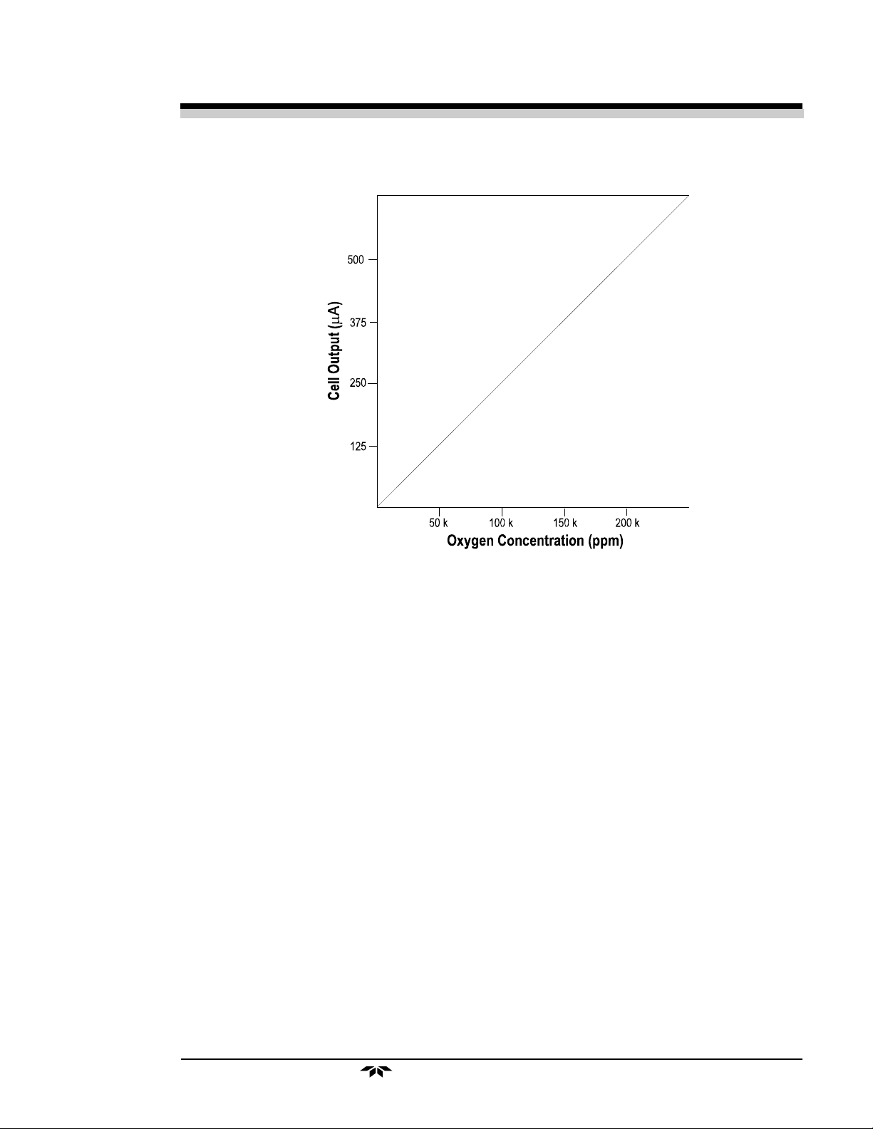
2.2.5 Calibration Characteristics
Given that the total pressure of the sample gas on the surface of the
Micro-Fuel Cell input is constant, a convenient characteristic of the cell is
that the current produced in an external circuit is directly proportional to the
rate at which oxygen molecules reach the cathode, and this rate is directly
proportional to the concentration of oxygen in the gaseous mixture. In other
words it has a linear characteristic curve, as shown in Figure 2-3. Measuring
circuits do not have to compensate for nonlinearities.
In addition, since there is zero output in the absence of oxygen, the
characteristic curve has close to an absolute zero (less than ± 0.2 ppm oxygen). Depending upon the application, zeroing may still be used to compensate for the combined zero offsets of the cell and the electronics.
2-4
Teledyne Analytical Instruments
Trace Oxygen Analyzer Operational Theory 2
Figure 2-3. Characteristic Input/Output Curve for a Micro-Fuel Cell
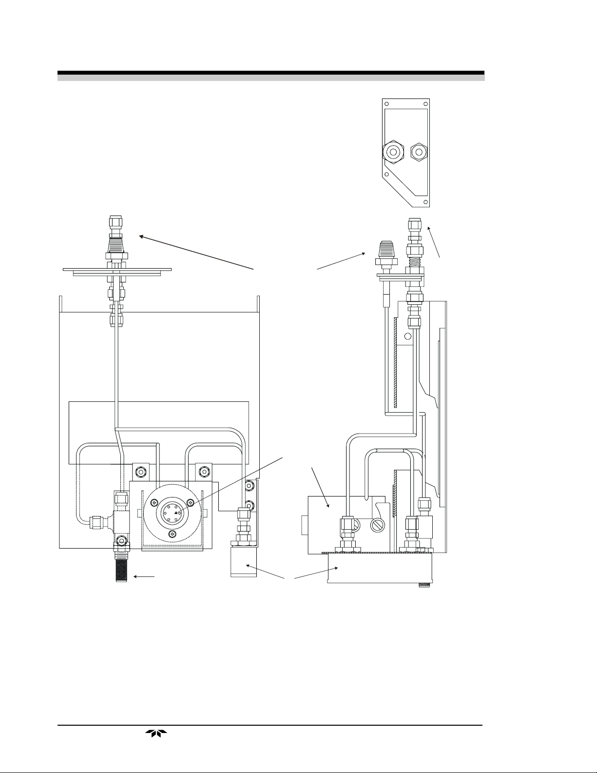
2.3 Sample System
The sample system delivers gases to the Micro-Fuel Cell sensor from
the analyzer rear panel inlet. Depending on the mode of operation either
sample or calibration gas is delivered.
The Model 3000TA-XL sample system is designed and fabricated to
ensure that the oxygen concentration of the gas is not altered as it travels
through the sample system.
The sample system for the standard instrument incorporates VCR tube
fittings for sample inlet and 1/4"outlet tube connections at the rear panel.
The sample or calibration gas that flows through the system is monitored by
a flowmeter downstream from the cell. Figure 2-4 shows the piping layout
and flow diagram for the standard model.
Teledyne Analytical Instruments
2-5
2 Operational Theory Model 3000TA-XL-EU
E
TOP
VCR
Sample In
SAMPLE IN
EXHAUST
RIGHT SID
Exhaust
Out
Cel l
Bl ock
Needle Valve
Fl owmet er
Figure 2-4: Piping Layout
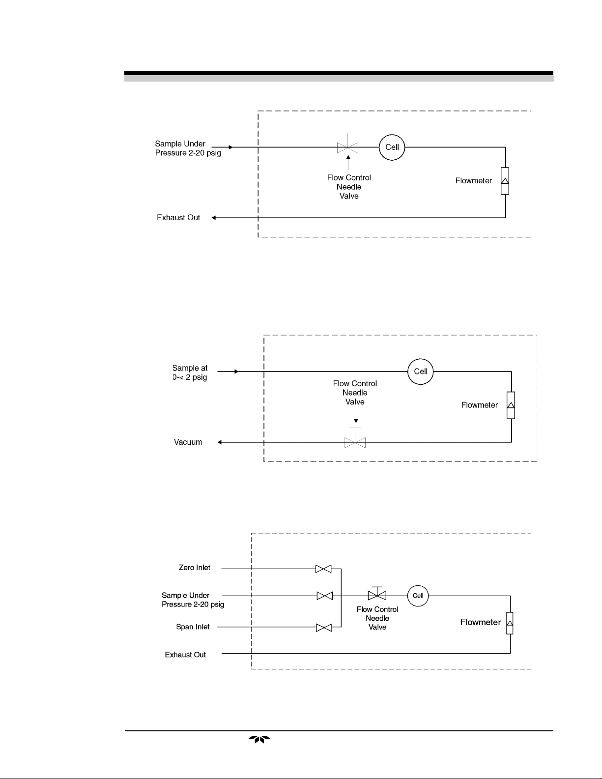
Figure 2-5 is the flow diagram for the sampling system. In the standard
instrument, calibration gases can be connected directly to the Sample In port
by teeing to the port with appropriate valves.
2-6
Teledyne Analytical Instruments
Trace Oxygen Analyzer Operational Theory 2
Figure 2-5: Flow Diagram-Sample Under Pressure
-Standard Model
-Do not exceed 10" Hg Vacuum-
Figure 2-5-1: Flow Diagram-Sample at Zero Pressure
Figure 2-5-2: Flow Diagram-Sample Under Pressure
-Model 3000TA-XL-VS
-Model 3000TA-XL-CV
Teledyne Analytical Instruments
2-7
2 Operational Theory Model 3000TA-XL-EU
2.4 Electronics and Signal Processing
The Model 3000TA-XL Trace Oxygen Analyzer uses an 8031 microcontroller with 32 kB of RAM and 128 kB of ROM to control all signal
processing, input/output, and display functions for the analyzer. System
power is supplied from a universal power supply module designed to be
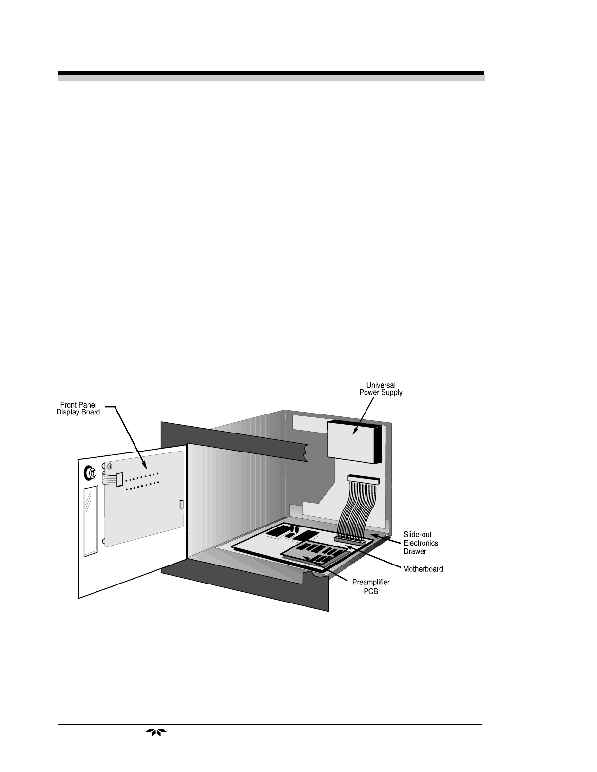
compatible with any international power source. Figure 2-6 shows the
location of the power supply and the main electronic PC boards.
The signal processing electronics including the microprocessor, analog
to digital, and digital to analog converters are located on the motherboard at
the bottom of the case. The preamplifier board is mounted on top of the
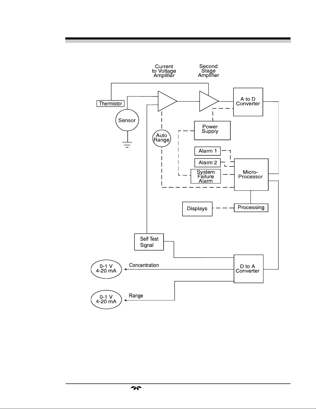
motherboard as shown in the figure. These boards are accessible after removing the back panel. Figure 2-7 is a block diagram of the Analyzer
electronics.
Figure 2-6: Electronic Component Location Inside the Model 3000TA-XL
2-8
Teledyne Analytical Instruments
Trace Oxygen Analyzer Operational Theory 2
Figure 2-7: Block Diagram of the Model 3000TA-XL Electronics
In the presence of oxygen the cell generates a current. A current to
voltage amplifier converts this current to a voltage, which is amplified in the
second stage amplifier.
The second stage amplifier also supplies temperature compensation for
the oxygen sensor output. This amplifier circuit incorporates a thermistor,
Teledyne Analytical Instruments
2-9

2 Operational Theory Model 3000TA-XL-EU
which is physically located in the cell block. The thermistor is a temperature
dependent resistor that changes the gain of the amplifier in proportion to the
temperature changes in the block. This change is inversely proportional to
the change in the cell output. The result is a signal that is temperature independent within a specified tolerance. The output from the second stage
amplifier is sent to an 18 bit analog to digital converter controlled by the
microprocessor.
The digital concentration signal along with input from the control panel
is processed by the microprocessor, and appropriate control signals are
directed to the display, alarms and communications port. The same digital
information is also sent to a 12 bit digital to analog converter that produces
the 4-20 mA dc and the 0-1 V dc analog concentration signal outputs, and
the analog range ID outputs.
Signals from the power supply are also monitored, and through the
microprocessor, the system failure alarm is activated if a malfunction is
detected.
2-10
Teledyne Analytical Instruments
 Loading...