

Teledyne 2750 User Manual
Turbine Generator Gas Analyzer
OPERATING INSTRUCTIONS FOR
MODEL 2750
Turbine Generator Gas Analyzer
P/N M76700
4/09/2012
DANGER
Toxic gases and or flammable liquids may be present in this monitoring system.
Personal protective equipment may be required when servicing this instrument.
Hazardous voltages exist on certain components internally which may persist
for a time even after the power is turned off and disconnected.
Only authorized personnel should conduct maintenance and/or servicing.
Before conducting any maintenance or servicing, consult with authorized
supervisor/manager.
Teledyne Analytical Instruments i

Model 2750
Copyright © 2012 Teledyne Analytical Instruments
All Rights Reserved. No part of this manual may be reproduced, transmitted, transcribed,
stored in a retrieval system, or translated into any other language or computer language in
whole or in part, in any form or by any means, whether it be electronic, mechanical,
magnetic, optical, manual, or otherwise, without the prior written consent of Teledyne
Analytical Instruments, 16830 Chestnut Street, City of Industry, CA 91749-1580.
Warranty
This equipment is sold subject to the mutual agreement that it is warranted by us free from
defects of material and of construction, and that our liability shall be limited to replacing or
repairing at our factory (without charge, except for transportation), or at customer plant at
our option, any material or construction in which defects become apparent within one year
from the date of shipment, except in cases where quotations or acknowledgements provide
for a shorter period. Components manufactured by others bear the warranty of their
manufacturer. This warranty does not cover defects caused by wear, accident, misuse,
neglect or repairs other than those performed by Teledyne or an authorized service center.
We assume no liability for direct or indirect damages of any kind and the purchaser by the
acceptance of the equipment will assume all liability for any damage which may result from
its use or misuse.
We reserve the right to employ any suitable material in the manufacture of our apparatus,
and to make any alterations in the dimensions, shape or weight of any parts, in so far as
such alterations do not adversely affect our warranty.
Important Notice
This instrument provides measurement readings to its use r, an d serves as a tool b y whic h
valuable data can be gathered. The information provided by the instrument may assist the user
in eliminating potential hazards caused by his process; however, it is essential that all
personnel involved in the use of the instrument or its interface, with the process being
measured, be properly trained in the process itself, as well as all instrumentation related to it.
The safety of personnel is ultimately the responsibility of those who control process
conditions. While this instrument may be able to provide early warning of imminent
danger, it has no control over process conditions, and it can be misused. In particular, any
alarm or control systems installed must be tested and understood, both as to how they
operate and as to how they can be defeated. Any safeguards required such as locks, labels,
or redundancy, must be provided by the user or specifically requested of Teledyne at the
time the order is placed.
Therefore, the purchaser must be aware of the hazardous process conditions. The purchaser
is responsible for the training of personnel, for providing hazard warning methods and
instrumentation per the appropriate standards, and for ensuring that hazard warning devices
and instrumentation are maintained and operated properly.
Teledyne Analytical Instruments, the manufacturer of this instrument, cannot accept
responsibility for conditions beyond its knowledge and control. No statement expressed or
implied by this document or any information disseminated by the manufacturer or its
agents, is to be construed as a warranty of adequate safety control under the user’s process
conditions.
Teledyne Analytical Instruments ii

Turbine Generator Gas Analyzer
Specific Model Information
The instrument for which this manual was supplied may
incorporate one or more options not supplied in the standard instrument.
Commonly available options are listed below, with check boxes. Any
that are incorporated in the instrument for which this manual is supplied
are indicated by a check mark in the box.
Instrument Serial Number: _______________________
Options Included in the Instrument with the Above Serial Number:
Teledyne Analytical Instruments iii
Model 2750
Safety Messages
Your safety and the safety of others is very important. We have
provided many important safety messages in this manual. Please read
these messages carefully.
A safety message alerts you to potential hazards that could hurt you
or others. Each safety message is associated with a safety alert symbol.
These symbols are found in the manual and inside the instrument. The
definition of these symbols is described below:
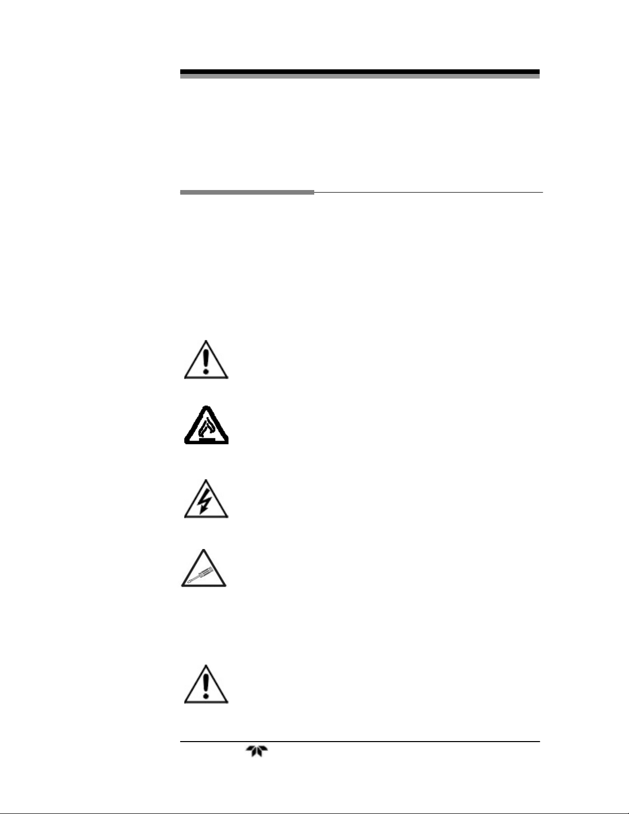
GENERAL WARNING/CAUTION: Refer to the instructions for details
on the specific danger. These cautions warn of specific
procedures which if not followed could cause bodily
Injury and/or damage the instrument.
CAUTION: Hot Surface Warning: This warning is specific to heated
components within the instrument. Failure to heed the
warning could result in serious burns to skin and
underlying tissue.
WARNING: Electrical Shock Hazard: Dangerous voltages appear within
this instrument. This warning is specific to an electrical
hazard existing at or nearby the component or procedure
under discussion. Failure to heed this warning could
result in injury and/or death from electrocution.
Technician Symbol: All operations marked with this symbol are to be
performed by qualified maintenance personnel only.
NOTE: Additional information and comments regarding a
No
Symbol
CAUTION: THE ANALYZER SHOULD ONLY BE USED FOR THE
specific component or procedure are highlighted in the
form of a note.
PURPOSE AND IN THE MANNER DESCRIBED IN
THIS MANUAL.
Teledyne Analytical Instruments iv

Turbine Generator Gas Analyzer
IF YOU USE THE ANALYZER IN A MANNER OTHER
THAN THAT FOR WHICH IT WAS INTENDED,
UNPREDICTABLE BEHAVIOR COULD RESULT
POSSIBLY ACCOMPANIED WITH HAZARDOUS
CONSEQUENCES.
This manual provides information designed to guide you through
the installation, calibration and operation of your new analyzer. Please
read this manual and keep it available.
Occasionally, some instruments are customized for a particular
application or features and/or options added per customer requests.
Please check the front of this manual for any additional information in
the form of an Addendum which discusses specific information,
procedures, cautions and warnings that may be peculiar to your
instrument.
Manuals do get lost. Additional manuals can be obtained from
Teledyne at the address given in the Appendix. Some of our manuals are
available in electronic form via the Internet. Please visit our website at:
www.teledyne-ai.com.
Teledyne Analytical Instruments v

Model 2750
Table of Contents
Safety Messages .......................................................................... iv
Table of Contents ......................................................................... vi
List of Figures ............................................................................. viii
List of Tables ................................................................................ ix
Introduction ................................................................................. 11
1.1 Overview 11
1.2 Analysis Ranges 11
1.3 Enclosure 12
1.4 Connections 13
1.5 Operator Interface 14
Theory of Operation ................................................................... 15
2.1 Thermal Conductivity 15
2.2 Electronics 17
Installation ................................................................................... 19
3.1 Electrical Connections 19
3.2 Gas Connections 20
3.2.1 Vent Line 21
3.2.2 Pressure Regulation 21
3.3 Calibration 22
3.3.1 Zero Calibration Procedure 23
3.3.2 Span Calibration Procedure 26
Setup and Operation ................................................................... 31
4.1 Setup 31
4.2 Operation 32
Teledyne Analytical Instruments vi

Turbine Generator Gas Analyzer
Maintenance ................................................................................. 35
5.1 Routine Maintenance 35
5.1.1 Instrument Cleaning 35
5.1.2 Periodic Calibration 35
5.1.3 Leak Checking 35
5.2 Troubleshooting 36
Appendix ...................................................................................... 39
A.1 Specifications 39
A.2 Spare Parts List 40
Teledyne Analytical Instruments vii

Model 2750
List of Figures
Figure 1-1: Front View of the Model 2750 ..................................... 12
Figure 1-2: Gas Connections ......................................................... 13
Figure 1-3: Electrical Connections ................................................. 13
Figure 1-4: Interface Panel ............................................................ 14
Figure 3-1: Electronics Block Diagram .......................................... 17
Figure 3-1: Electrical Connections ................................................. 20
Figure 3-2: Gas Connections ......................................................... 21
Figure 3-3: Interface Panel Showing Calibration Switch Position .. 23
Figure 3-4: Interface Panel Showing Calibration Switch Position .. 24
Figure 3-5: H2/CO2 Trim Pot ......................................................... 24
Figure 3-6: Cal Switch in H2/AIR Position ..................................... 25
Figure 3-7: H2/AIR Zero Trimpot ................................................... 25
Figure 3-8: Range Switch in AIR/CO2 Position ............................. 27
Figure 3-9: AIR/CO2 Span Trimpot ............................................... 27
Figure 3-10: Range Switch in H2/CO2 Position ............................. 28
Figure 3-11: H2/CO2 Span Trimpot ............................................... 28
Figure 3-12: Range Switch in H2/AIR Position .............................. 28
Figure 3-13: H2/AIR Span Trimpot ................................................ 29
Figure 4-1: Power and Output Connections to the Model 2750 ..... 32
Teledyne Analytical Instruments viii

Turbine Generator Gas Analyzer
List of Tables
Table 2-1: Thermal Conductivity for Selected Gases .................... 15
Table 4-1: Troubleshooting ............................................................ 36
Teledyne Analytical Instruments ix
Model 2750
DANGER
COMBUSTIBLE GAS USAGE
This is a general purpose instrument designed for use in a
non-hazardous area. It is the customer's responsibility to
ensure safety especially when combustible gases are being
analyzed. The potential for gas leaks always exist.
The operator of this equipment should fully understand the
principles of operation for this instrument. Misuse of this
product in any manner, tampering with its components, or
unauthorized substitution of any component may adversely
affect the safety of this instrument.
WARNING
Since the use of this instrument is beyond the control of
Teledyne, no responsibility by Teledyne, its affiliates, and
agents for damage or injury from misuse or neglect of this
equipment is implied or assumed.
WARNING: USING NON-COMBUSTIBLE GASES CAN EXPOSE
THE USER TO THE RISK OF ASPHYXIATION.
ALWAYS USE CAUTION WHEN WORKING WITH ANY
GAS IN CONTAINED AREAS; MAKE SURE THERE IS
PROPER VENTILATION AVAILABLE IN THE WORK
AREA. TAI RECOMMENDS THE USE OF SAFETY
MONITORS TO ENHANCE USER SAFETY.
WARNING: THERE ARE NO USER SERVICEABLE PARTS
CONTAINED IN THIS ANALYZER. FOR SERVICE OR
REPAIR, CONTACT TELEDYNE ANALYTICAL
INSTRUMENTS FOR QUALIFIED SERVICE
PERSONNEL OR AN RMA NUMBER.
Teledyne Analytical Instruments x

Turbine Generator Gas Analyzer Introduction
Introduction
1.1 Overview
The Model 2750 Turbine Generator Gas analyzer is a portable
microcontroller based three-channel analyzer designed to measure the
concentration of a single gas component in a binary mixture of gases. A
special thermal conductivity cell responds to the difference in thermal
conductivity between the components of a gas mixture and produces a
signal output which is linearized over the specific range of interest. Each
channel is separately linearized for enhanced accuracy. The cell is
maintained at a fixed temperature to minimize any thermally induced
error.
This analyzer is specifically designed for use during the
maintenance of turbine generators. The three ranges allow the user to
monitor the turbine’s blanketing gas as the turbine is in use or during
maintenance. It provides a range of 80%- 100% hydrogen in a
background (impurity) of air for hydrogen purity monitoring. Two
ranges, 0-100% hydrogen in a background of CO
background of CO2 are used to monitor the blanketing gas during the
purge cycles. During normal operation the turbine is blanketed with
100% hydrogen. For maintenance the hydrogen is first purged from the
enclosure with CO2 for fire safety. This process is followed by an air
purge for worker safety. This process is reversed prior to bringing the
turbine back into service.
, and 0-100% air in a
2
1.2 Analysis Ranges
The Model 2750 has 3 separate user selectable analysis ranges
controlled by a 3-position rotary switch.
Standard analysis ranges include:
0-100% hydrogen in CO2
0-100% air in CO2
80-100% hydrogen in air
Teledyne Analytical Instruments 11
Introduction Model 2750
The thermal conductivity sensor senses the thermal conductivity
(T/C) or heat transfer rate of the sampled gas mixture and produces an
electrical signal proportional to its heat conductivity. The T/C of the two
gases in the mixture are significantly different. Because of this
difference, the T/C of the gas mixture will be proportional to the
percentage of each gas in the mixture. The resulting raw signal from the
sensor is linearized and ultimately converted into a concentration
readout on the digital display. Although it is possible to obtain a digital
readout using almost any binary mixture of gases with a reasonable
thermal conductivity difference, this instrument is designed and
internally calibrated for only those gases and analysis ranges listed
above. Any other mixture will produce erroneous results. Contact the
factory if your application requires an analysis range not listed above.
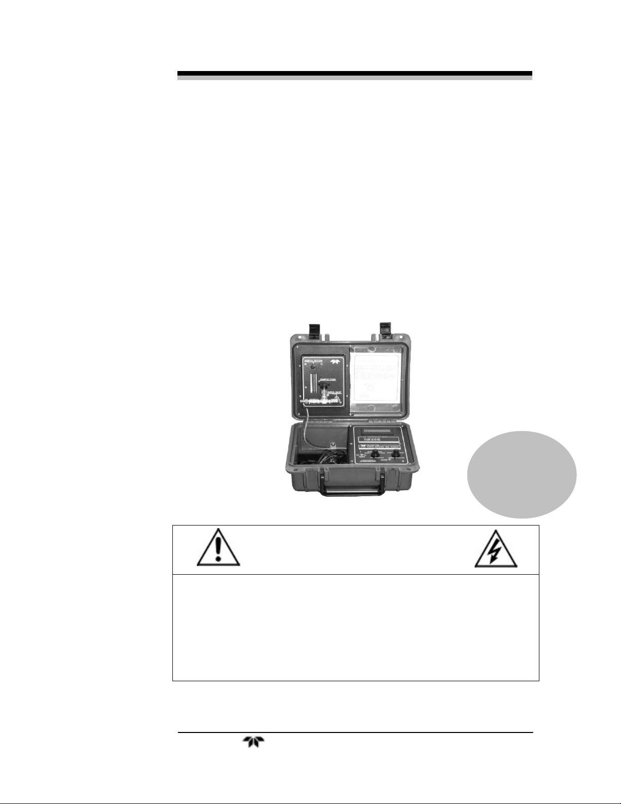
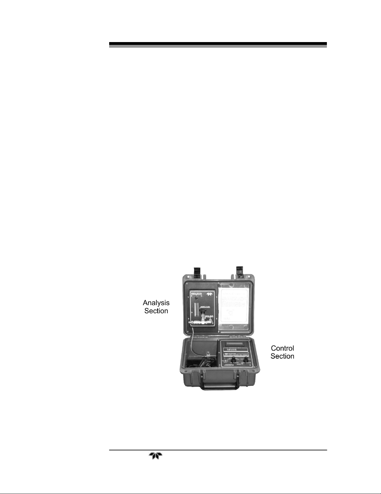
1.3 Enclosure
The Model 2750 is a portable instrument housed in a rugged impact
resistant NEMA 4X polyethylene enclosure which can easily be set up at
the point of analysis and field-calibrated. The top of the case opens to
reveal the operator interface panel. The analysis section is located in the
cover section of the enclosure. See Figure 1-1.
Figure 1-1: Front View of the Model 2750
Teledyne Analytical Instruments 12
 Loading...