

Page 1
Advanced Pollution Instrumentation
A Teledyne Technologies Company
TELEDYNE
INSTRUMENTS
INSTRUCTION MANUAL
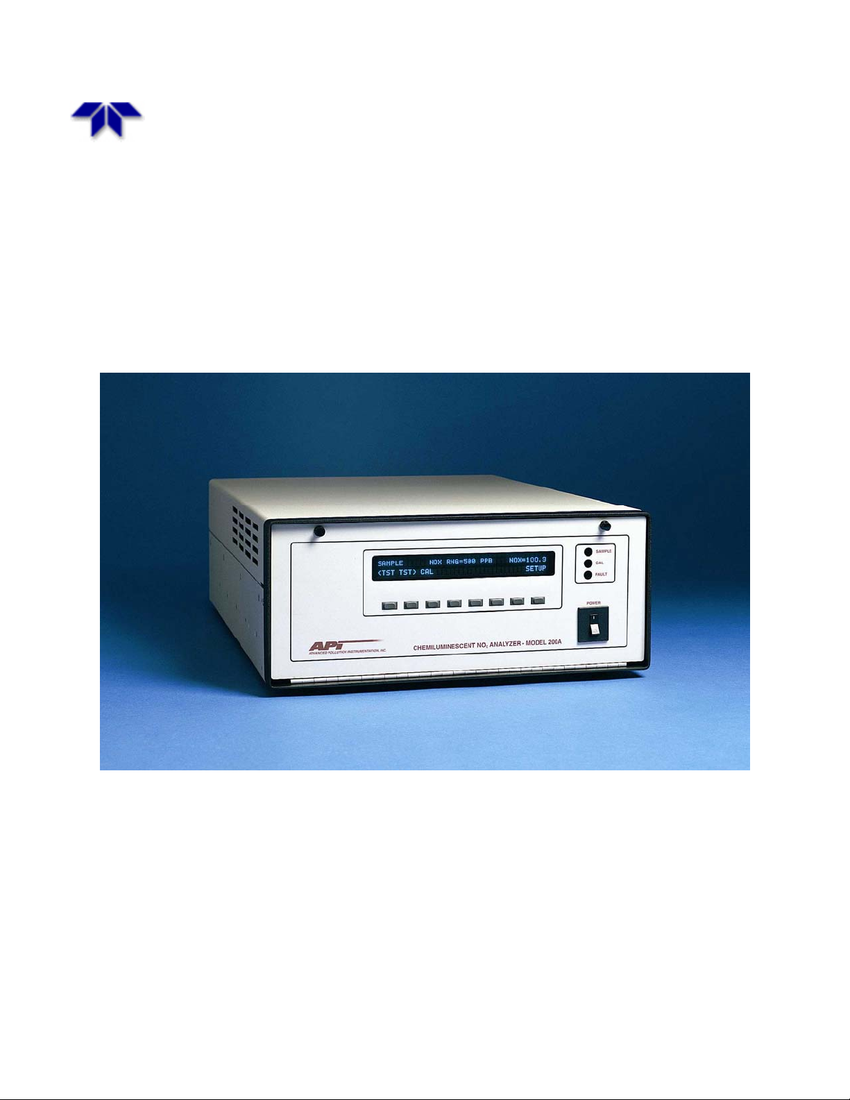
Chemiluminescent
NO/NO
/NOX ANALYZER
2
Model 200A
© Teledyne Advanced Pollution Instrumentation
(T-API)
9480 Carroll Park Drive
San Diego, CA 92121-5201
TOLL-FREE: 800-324-5190
FAX: 858-657-9816
TEL: 858-657-9800
E-MAIL: api-sales@teledyne.com
WEB SITE: www.teledyne-api.com
Page 2

Teledyne API, Model 200A NOX Analyzer Instruction Manual, 02246, Rev. G, DCN 5247
HIGHLIGHTS
The purpose of this Highlights Page is to list the changes that were incorporated into this Manual per
DCN 5247.
Chapter / Page Number Description
Title Page
Text – All Pages
TOC / x
3 / 3-3, 3-4
8 / 8-15
10 / 10-1 thru 10-7
10 / 10-7, 10-8
Changed Revision number and date.
Added DCN number to footer.
Changed Revision number and date.
Added DCN to all footers of Text, P/N 02246G.
Added “PRINTED DOCUMENTS ARE UNCONTROLLED” to all
footers of Instruction Manual, P/N 02246G.
Updated List of Figures in TOC.
Updated Warranty Section.
Added note to replace the 5 dessicant bags if black PMT cover for
the Sensor Assembly is removed.
Updated Spare Parts List, Tables 10-1 thru 10-6.
Added Tables 10-7 and 10-8 for new Expendables Kits.
PRINTED DOCUMENTS ARE UNCONTROLLED
Page 3

THIS PAGE IS INTENTIONALLY LEFT BLANK
Page 4

TELEDYNE
INSTRUMENTS
Advanced Pollution Instrumentation
A Teledyne Technolog i es Company
INSTRUCTION MANUAL
MODEL 200A
NITROGEN OXIDE ANALYZER
TELEDYNE ADVANCED POLLUTION INSTRUMENTATION
Copyright 2005 API Inc.
(TELEDYNE API)
9480 CARROLL PARK DRIVE
SAN DIEGO, CA 92121-5201
TOLL-FREE: 800-324-5190
FAX: 858-657-9816
TEL: 858-657-9800
E-MAIL: api-sales@teledyne.com
WEB SITE: www.teledyne-api.com
02246 REV. G
DCN 5247
10 December 2008
Page 5

THIS PAGE IS INTENTIONALLY LEFT BLANK
Page 6
Teledyne API Model 200A NOX Analyzer Instruction Manual, 02246, Rev. G, DCN 5247
SAFETY MESSAGES
Your safety and the safety of others is very important. We have provided many important safety
messages in this manual. Please read these messages carefully.
A safety message alerts you to potential hazards that could hurt you or others. Each safety
message is associated with a safety alert symbol. These symbols are found in the manual and
inside the instrument. The definition of these symbols is described below:
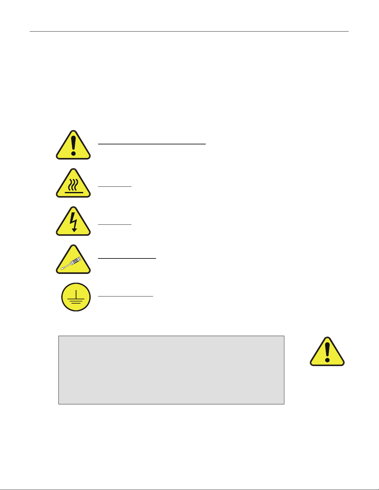
GENERAL WARNING/CAUTION: Refer to the instructions for details on the
specific danger.
CAUTION: Hot Surface Warning
CAUTION: Electrical Shock Hazard
Technician Symbol: All operations marked with this symbol are to be performed
by qualified maintenance personnel only.
Electrical Ground: This symbol inside the instrument marks the central safety
grounding point for the instrument.
CAUTION
The analyzer should only be used for the purpose
and in the manner described in this manual.
If you use the analyzer in a manner other than that for which
it was intended, unpredictable behavior could ensue with
possible hazardous consequences.
i
PRINTED DOCUMENTS ARE UNCONTROLLED
Page 7

Teledyne API Model 200A NOX Analyzer Instruction Manual, 02246, Rev. G, DCN 5247
THIS PAGE IS INTENTIONALLY LEFT BLANK
ii
PRINTED DOCUMENTS ARE UNCONTROLLED
Page 8

Teledyne API Model 200A NOX Analyzer Instruction Manual, 02246, Rev. G, DCN 5247
TABLE OF CONTENTS
SAFETY MESSAGES .......................................................................................................I
TABLE OF CONTENTS................................................................................................III
LIST OF FIGURES .......................................................................................................VII
LIST OF TABLES .......................................................................................................VIII
1 HOW TO USE THIS MANUAL ............................................................................... 1-1
2 GETTING STARTED ................................................................................................ 2-1
2.1 UNPACKING..................................................................................................................................... 2-1
2.2 ELECTRICAL AND PNEUMATIC CONNECTIONS.................................................................................2-1
2.3 INITIAL OPERATION ........................................................................................................................ 2-6
3 SPECIFICATIONS, AGENCY APPROVALS, WARRANTY.............................. 3-1
3.1 SPECIFICATIONS ..............................................................................................................................3-1
3.2 EPA EQUIVALENCY DESIGNATION ................................................................................................. 3-2
3.3 WARRANTY..................................................................................................................................... 3-3
4 THE M200A NOX ANALYZER ................................................................................ 4-1
4.1 PRINCIPLE OF OPERATION ...............................................................................................................4-1
4.2 OPERATION SUMMARY.................................................................................................................... 4-3
4.2.1 Sensor Module, Reaction Cell, Detector ................................................................................4-3
4.2.2 Pneumatic Sensor Board......................................................................................................... 4-3
4.2.3 Computer Hardware and Software.......................................................................................... 4-4
4.2.4 V/F Board................................................................................................................................ 4-4
4.2.5 Front Panel.............................................................................................................................. 4-4
4.2.6 Power Supply Module ............................................................................................................ 4-6
4.2.7 Pump, Valves, Pneumatic System ..........................................................................................4-6
4.2.8 Ozone Generator ..................................................................................................................... 4-9
4.2.9 Molydbenum Converter.......................................................................................................... 4-9
5 SOFTWARE FEATURES.......................................................................................... 5-1
5.1
INDEX TO FRONT PANEL MENUS .................................................................................................... 5-1
5.1.1 Sample Menu .......................................................................................................................... 5-4
5.1.2 Set-Up Menu...........................................................................................................................5-5
SAMPLE MODE ................................................................................................................................5-8
5.2
5.2.1 Test Functions.........................................................................................................................5-8
iii
PRINTED DOCUMENTS ARE UNCONTROLLED
Page 9

Teledyne API Model 200A NOX Analyzer Instruction Manual, 02246, Rev. G, DCN 5247
5.2.2 CAL, CALS, CALZ, Calibration Functions ......................................................................... 5-12
5.3 SET-UP MODE...............................................................................................................................5-14
5.3.1 Configuration Information (CFG)......................................................................................... 5-14
5.3.2 Automatic Calibration (AutoCal) .........................................................................................5-14
5.3.3 Data Acquisition System (DAS)...........................................................................................5-14
5.3.4 Range Menu.......................................................................................................................... 5-16
5.3.5 Password Enable ................................................................................................................... 5-20
5.3.6 Time of Day Clock................................................................................................................ 5-20
5.3.7 Diagnostic Mode...................................................................................................................5-20
5.3.8 Communications Menu.........................................................................................................5-20
5.3.9 Variables Menu (VARS) ...................................................................................................... 5-21
5.3.10 M200A Operating Modes ...................................................................................................5-21
5.4 STATUS OUTPUT ........................................................................................................................... 5-22
5.5 RS-232 INTERFACE ....................................................................................................................... 5-23
5.5.1 Setting Up the RS-232 Interface........................................................................................... 5-24
5.5.2 Command Summary ............................................................................................................. 5-28
5.5.3 TEST Commands and Messages ..........................................................................................5-32
5.5.4 WARNING Commands and Messages................................................................................. 5-33
5.5.5 CALIBRATION Commands and Messages......................................................................... 5-34
5.5.6 DIAGNOSTIC Commands and Messages............................................................................ 5-36
5.5.7 DAS Commands and Message.............................................................................................. 5-37
5.5.8 Internal Variables.................................................................................................................. 5-39
6 OPTIONAL HARDWARE AND SOFTWARE....................................................... 6-1
6.1 RACK MOUNT OPTIONS .................................................................................................................. 6-1
6.2 ZERO/SPAN VALVES ....................................................................................................................... 6-1
6.3 INTERNAL ZERO/SPAN (IZS)........................................................................................................... 6-3
6.4 AUTOCAL - SETUP OF IZS AND ZERO/SPAN VALVES....................................................................... 6-3
6.5 PERMEATION TUBE ......................................................................................................................... 6-5
6.6 4-20 MA CURRENT LOOP OUTPUT .................................................................................................. 6-8
7 CALIBRATION AND ZERO/SPAN CHECKS....................................................... 7-1
MANUAL ZERO/SPAN CHECK OR CAL WITH ZERO/SPAN GAS IN THE SAMPLE PORT ...................... 7-4
7.1
7.2 MANUAL ZERO/SPAN CHECK OR CALIBRATION WITH ZERO/SPAN VALVES OPTION....................... 7-6
7.3 MANUAL ZERO/SPAN CHECK WITH IZS OPTION ............................................................................. 7-7
7.4
AUTOMATIC ZERO/SPAN CHECK.....................................................................................................7-7
DYNAMIC ZERO/SPAN CALIBRATION .............................................................................................. 7-7
7.5
7.6 CALIBRATE ON NO
7.7
USE OF ZERO/SPAN VALVES OR IZS WITH REMOTE CONTACT CLOSURE...................................... 7-11
7.8 EPA PROTOCOL CALIBRATION ..................................................................................................... 7-12
7.8.1 Calibration of Equipment...................................................................................................... 7-12
7.8.2 Calibration Gas and Zero Air Sources.................................................................................. 7-14
7.8.3 Data Recording Device......................................................................................................... 7-15
7.8.4 Gas Phase Titration (GPT) System....................................................................................... 7-16
7.8.5 Dynamic Multipoint Calibration Procedure .........................................................................7-20
PERMEATION TUBE ......................................................................................... 7-9
2
iv
PRINTED DOCUMENTS ARE UNCONTROLLED
Page 10

Teledyne API Model 200A NOX Analyzer Instruction Manual, 02246, Rev. G, DCN 5247
7.8.6 Moly Converter Efficiency ...................................................................................................7-25
7.8.7 Calibration Frequency........................................................................................................... 7-27
7.8.8 Other Quality Assurance Procedures.................................................................................... 7-27
7.8.9 Summary of Quality Assurance Checks ............................................................................... 7-29
7.8.10 ZERO and SPAN Checks ...................................................................................................7-30
7.8.11 Recommended Standards for Establishing Traceability.....................................................7-31
7.8.12 Certification Procedures of Working Standards ................................................................. 7-32
7.9 CALIBRATION OF INDEPENDENT RANGES OR AUTORANGING ........................................................ 7-34
7.9.1 Zero Calibration with AutoRange or Independent Range .................................................... 7-34
7.9.2 Span Calibration with AutoRange or Independent Range....................................................7-34
7.10 CALIBRATION QUALITY .............................................................................................................. 7-35
7.11 REFERENCES ...............................................................................................................................7-37
8 MAINTENANCE........................................................................................................ 8-1
8.1 MAINTENANCE SCHEDULE .............................................................................................................. 8-1
8.2 REPLACING THE SAMPLE PARTICULATE FILTER..............................................................................8-3
8.3 REPLACING THE OZONE SCRUBBER CHARCOAL .............................................................................. 8-5
8.4 REPLACING THE PERMEATION.........................................................................................................8-5
8.5 REPLACING THE IZS ZERO AIR SCRUBBER...................................................................................... 8-6
8.6 REPLACING THE MOLYBDENUM CONVERTER.................................................................................. 8-7
8.7 CLEANING THE REACTION CELL ..................................................................................................... 8-9
8.8 PNEUMATIC LINE INSPECTION.......................................................................................................8-11
8.9 LEAK CHECK PROCEDURE............................................................................................................. 8-15
8.10 LIGHT LEAK CHECK PROCEDURE ................................................................................................ 8-16
8.11 PROM REPLACEMENT PROCEDURE .............................................................................................. 8-16
9 TROUBLESHOOTING, ADJUSTMENTS.............................................................. 9-1
9.1 OPERATION VERIFICATION-M200A DIAGNOSTIC TECHNIQUES ...................................................... 9-3
9.1.1 Fault Diagnosis with TEST Variables .................................................................................... 9-3
9.1.2 Fault Diagnosis with WARNING Messages .......................................................................... 9-8
9.1.3 Fault Diagnosis Using DIAGNOSTIC Mode....................................................................... 9-11
9.1.4 M200A Internal Variables .................................................................................................... 9-18
9.1.5 Test Channel Analog Output ................................................................................................9-20
9.1.6 Factory Calibration Procedure .............................................................................................. 9-23
PERFORMANCE PROBLEMS ............................................................................................................ 9-26
9.2
9.2.1 AC Power Check................................................................................................................... 9-27
9.2.2 Flow Check ........................................................................................................................... 9-27
9.2.3 No Response to Sample ........................................................................................................9-28
9.2.4 Negative Output.................................................................................................................... 9-29
9.2.5 Excessive Noise ....................................................................................................................9-29
9.2.6 Unstable Span ....................................................................................................................... 9-30
9.2.7 Unstable Zero........................................................................................................................ 9-31
9.2.8 Inability to Span....................................................................................................................9-31
9.2.9 Inability to Zero .................................................................................................................... 9-32
9.2.10 Non-Linear Response ......................................................................................................... 9-33
v
PRINTED DOCUMENTS ARE UNCONTROLLED
Page 11

Teledyne API Model 200A NOX Analyzer Instruction Manual, 02246, Rev. G, DCN 5247
9.2.11 Slow Response.................................................................................................................... 9-34
9.2.12 Analog Output Doesn't Agree with Display Concentration................................................ 9-34
9.3 SUBSYSTEM TROUBLESHOOTING AND ADJUSTMENTS ................................................................... 9-35
9.3.1 Computer, Display, Keyboard .............................................................................................. 9-35
9.3.2 RS-232 Communications...................................................................................................... 9-38
9.3.3 Voltage/Frequency (V/F) Board ...........................................................................................9-41
9.3.4 Status/Temp Board................................................................................................................9-47
9.3.5 Power Supply Module .......................................................................................................... 9-49
9.3.6 Ozone Generator ................................................................................................................... 9-54
9.3.7 Flow/Pressure Sensor............................................................................................................ 9-57
9.3.8 NOx Sensor Module .............................................................................................................. 9-62
9.3.9 Z/S Valves & IZS Permeation Tube Oven ...........................................................................9-66
9.3.10 Pneumatic System...............................................................................................................9-67
10 M200A SPARE PARTS LIST................................................................................10-1
APPENDIX A ELECTRICAL SCHEMATICS ....................................................A-1
vi
PRINTED DOCUMENTS ARE UNCONTROLLED
Page 12

Teledyne API Model 200A NOX Analyzer Instruction Manual, 02246, Rev. G, DCN 5247
LIST OF FIGURES
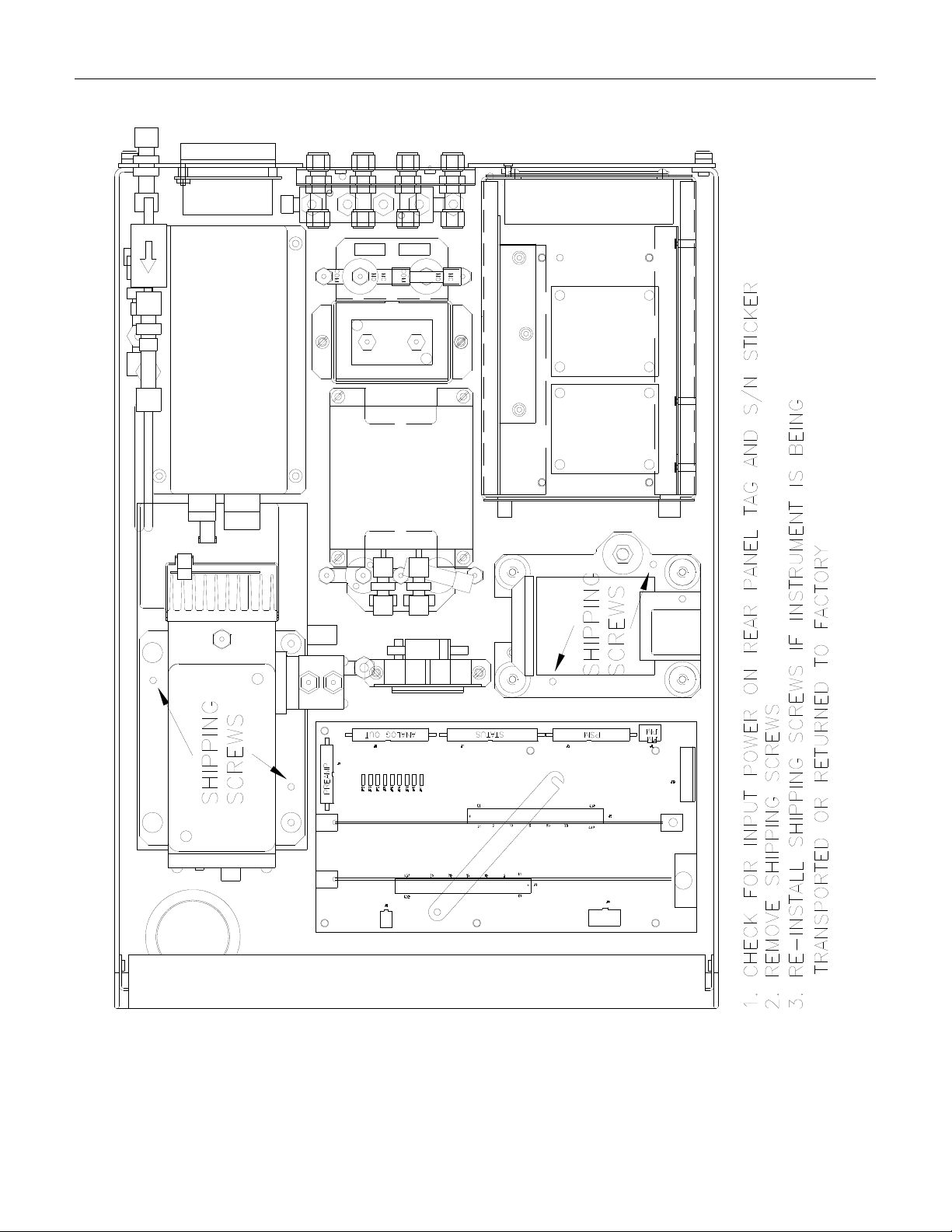
FIGURE 2-1: REMOVAL OF SHIPPING SCREWS & CHECK FOR CORRECT POWER ....................................... 2-3
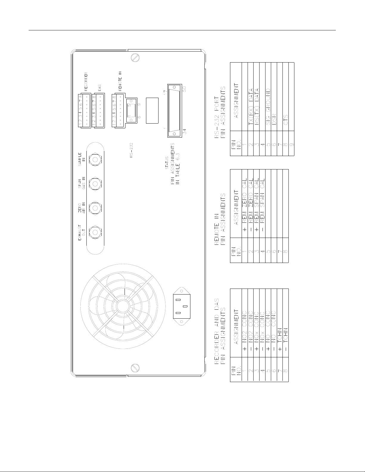
FIGURE 2-2: REAR PANEL ........................................................................................................................ 2-4
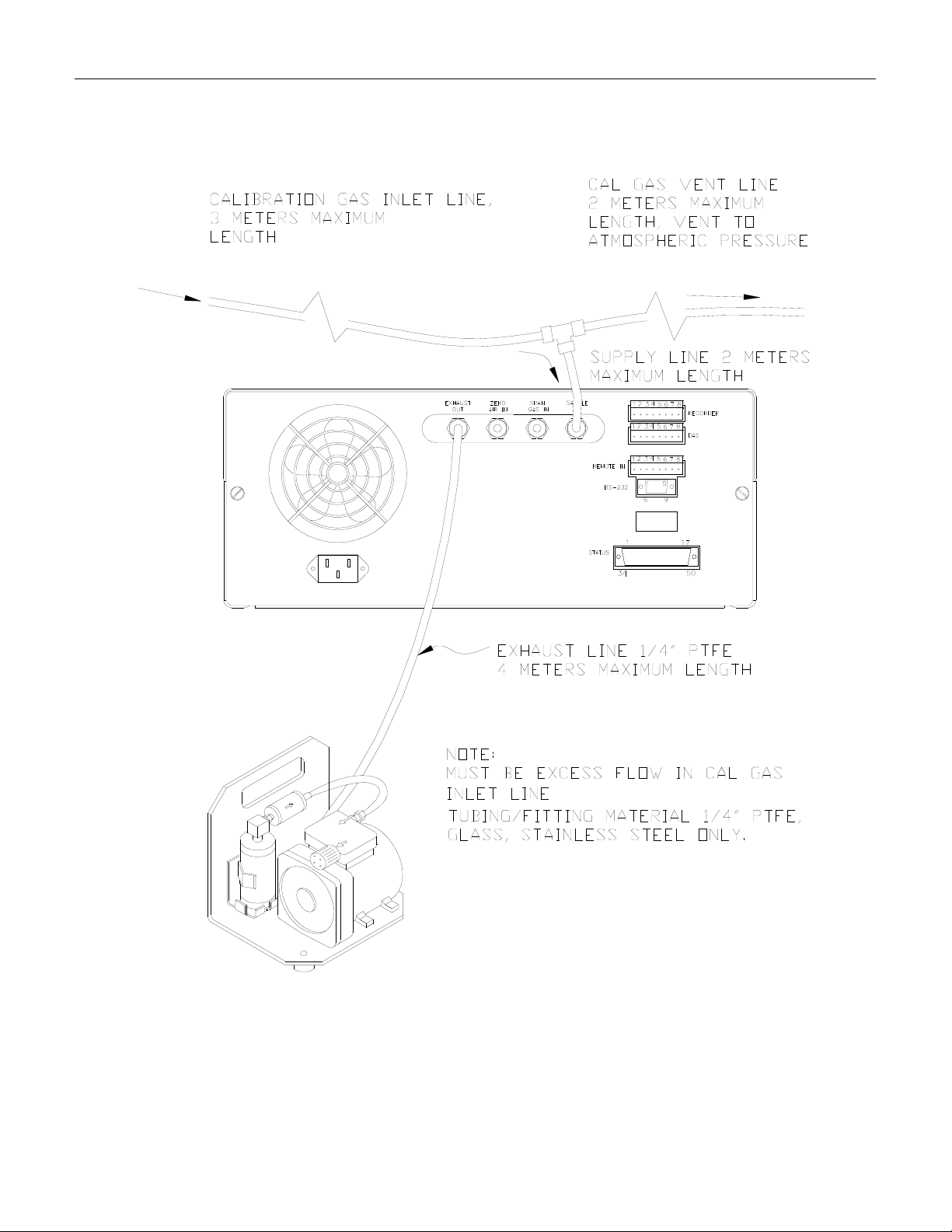
FIGURE 2-3: INLET AND EXHAUST VENTING ............................................................................................2-5
FIGURE 2-4: FRONT PANEL .................................................................................................................... 2-10
FIGURE 2-5: ASSEMBLY LAYOUT ........................................................................................................... 2-11
FIGURE 4-1: BLOCK DIAGRAM ................................................................................................................. 4-2
FIGURE 4-2: EXTERNAL PUMP PACK ........................................................................................................ 4-8
FIGURE 5-1: SAMPLE MENU TREE............................................................................................................5-2
IGURE 5-2: SETUP MENU TREE............................................................................................................... 5-3
F
F
IGURE 6-1: IZS OPTION - PERMEATION TUBE INSTALLATION ................................................................ 6-7
FIGURE 7-1: CALIBRATION SETUP ............................................................................................................ 7-3
FIGURE 7-2: DIAGRAM OF GPT CALIBRATION SYSTEM ......................................................................... 7-21
FIGURE 8-1: REPLACING THE PARTICULATE FILTER................................................................................. 8-4
FIGURE 8-2: MOLYBDENUM CONVERTER ASSEMBLY .............................................................................. 8-8
FIGURE 8-3: REACTION CELL ASSEMBLY............................................................................................... 8-10
FIGURE 8-4: PNEUMATIC DIAGRAM - STANDARD CONFIGURATION ....................................................... 8-12
FIGURE 8-5: PNEUMATIC DIAGRAM WITH ZERO/SPAN VALVE OPTION .................................................. 8-13
FIGURE 8-6: PNEUMATIC DIAGRAM WITH IZS OPTION .......................................................................... 8-14
FIGURE 9-1: SPAN CALIBRATION VOLTAGE ...........................................................................................9-25
FIGURE 9-2: CPU BOARD JUMPER SETTINGS .........................................................................................9-36
FIGURE 9-3: RS-232 PIN ASSIGNMENTS................................................................................................9-40
FIGURE 9-4: V/F BOARD SETTINGS ........................................................................................................ 9-46
FIGURE 9-5: POWER SUPPLY MODULE LAYOUT.....................................................................................9-51
FIGURE 9-6: ELECTRICAL BLOCK DIAGRAM .......................................................................................... 9-52
FIGURE 9-7: OZONE GENERATOR SUBSYSTEM ....................................................................................... 9-56
FIGURE 9-8: FLOW/PRESSURE SENSOR...................................................................................................9-59
IGURE 9-9: NOX SENSOR MODULE ....................................................................................................... 9-60
F
FIGURE 9-10: NO
F
IGURE 9-11: PMT COOLER SUBSYSTEM............................................................................................... 9-63
FIGURE 9-12: HIGH VOLTAGE POWER SUPPLY....................................................................................... 9-65
SENSOR MODULE ..................................................................................................... 9-61
X
vii
PRINTED DOCUMENTS ARE UNCONTROLLED
Page 13

Teledyne API Model 200A NOX Analyzer Instruction Manual, 02246, Rev. G, DCN 5247
LIST OF TABLES
TABLE 2-2-1: REMOVAL OF SHIPPING SCREWS & CHECK FOR CORRECT POWER .....................................2-3
TABLE 2-2-2: REAR PANEL ......................................................................................................................2-4
TABLE 2-2-3: INLET AND EXHAUST VENTING .......................................................................................... 2-5
TABLE 2-2-4: FRONT PANEL .................................................................................................................. 2-10
TABLE 2-2-5: ASSEMBLY LAYOUT.........................................................................................................2-11
TABLE 2-2-6: FINAL TEST AND CALIBRATION VALUES.......................................................................... 2-12
TABLE 2-1: FINAL TEST AND CALIBRATION VALUES (CONTINUED)....................................................... 2-13
TABLE 4-4-1: BLOCK DIAGRAM...............................................................................................................4-2
ABLE 4-4-2: FRONT PANEL STATUS LED'S ............................................................................................4-5
T
T
ABLE 4-4-3: EXTERNAL PUMP PACK ...................................................................................................... 4-8
TABLE 4-4-4: OZONE GENERATOR START-UP TIMING ............................................................................. 4-9
TABLE 5-5-1: SAMPLE MENU TREE.......................................................................................................... 5-2
TABLE 5-5-2: SETUP MENU TREE ............................................................................................................ 5-3
TABLE 5-5-3: M200A SAMPLE MENU STRUCTURE..................................................................................5-4
TABLE 5-5-4: M200A SETUP MENU STRUCTURE..................................................................................... 5-5
TABLE 5-5-5: M200A MENU STRUCTURE - SETUP MENU #2................................................................... 5-6
TABLE 5-5-6: M200A MENU STRUCTURE - SETUP MENU #3................................................................... 5-6
TABLE 5-5-7: DAS DATA CHANNEL EDITING........................................................................................5-16
TABLE 5-5-8: CALIBRATE, SETUP PASSWORDS ......................................................................................5-20
TABLE 5-5-9: M200A OPERATING MODES ............................................................................................5-22
TABLE 5-5-10: STATUS OUTPUT PIN ASSIGNMENTS .............................................................................. 5-23
TABLE 5-5-11: RS-232 PORT SETUP - FRONT PANEL ............................................................................. 5-25
TABLE 5-5-12: RS-232 SWITCHING FROM TERMINAL MODE TO COMPUTER MODE ..............................5-26
TABLE 5-5-13: RS-232 TERMINAL MODE EDITING KEYS ...................................................................... 5-26
TABLE 5-5-14: RS-232 COMMAND SUMMARY....................................................................................... 5-29
TABLE 5-5-15: RS-232 COMMAND SUMMARY....................................................................................... 5-30
TABLE 5-5-16: RS-232 INTERFACE COMMAND TYPES...........................................................................5-31
ABLE 5-5-17: RS-232 TEST MESSAGES ............................................................................................... 5-32
T
TABLE 5-5-18: RS-232 WARNING MESSAGES ....................................................................................... 5-33
T
ABLE 5-5-19: RS-232 CALIBRATION COMMANDS................................................................................ 5-34
TABLE 5-5-20: RS-232 CALIBRATION EXAMPLES.................................................................................. 5-35
ABLE 5-5-21: RS-232 CALIBRATION MESSAGES.................................................................................. 5-36
T
TABLE 5-5-22: RS-232 DIAGNOSTIC COMMAND SUMMARY .................................................................. 5-37
TABLE 6-6-1: ZERO/SPAN VALVE OPERATION......................................................................................... 6-2
T
ABLE 6-6-2: IZS SEQUENCE MODES ......................................................................................................6-3
ABLE 6-6-3: IZS SEQUENCE ATTRIBUTES .............................................................................................. 6-4
T
TABLE 6-6-4: IZS SEQUENCE EXAMPLE................................................................................................... 6-4
T
ABLE 6-6-5: EXAMPLE OF AUTOCAL SETUP .......................................................................................... 6-5
TABLE 6-6-6: IZS OPTION - PERMEATION TUBE INSTALLATION ..............................................................6-7
ABLE 7-7-1: TYPES OF ZERO/SPAN CHECK AND CALIBRATION..............................................................7-2
T
T
ABLE 7-7-2: CALIBRATION SETUP.......................................................................................................... 7-3
TABLE 7-7-3: MANUAL ZERO CALIBRATION PROCEDURE - ZERO GAS THRU SAMPLE PORT ................... 7-4
viii
PRINTED DOCUMENTS ARE UNCONTROLLED
Page 14

Teledyne API Model 200A NOX Analyzer Instruction Manual, 02246, Rev. G, DCN 5247
TABLE 7-7-4: ENTER EXPECTED SPAN GAS CONCENTRATIONS PROCEDURE ........................................... 7-5
TABLE 7-7-5: MANUAL SPAN CALIBRATION PROCEDURE - SPAN GAS THRU SAMPLE PORT .................... 7-5
TABLE 7-7-6: MANUAL ZERO CALIBRATION PROCEDURE - Z/S VALVES ................................................. 7-6
TABLE 7-7-7: MANUAL SPAN CALIBRATION PROCEDURE - Z/S VALVES ................................................. 7-6
TABLE 7-7-8: ENABLING DYNAMIC ZERO/SPAN ......................................................................................7-8
TABLE 7-7-9: ENABLING CAL-ON-NO2 ............................................................................................... 7-10
TABLE 7-7-10: IZS OR Z/S VALVES MODES WITH REMOTE CONTACT CLOSURE...................................7-11
TABLE 7-7-11: ACTIVITY MATRIX FOR CALIBRATION EQUIPMENT AND SUPPLIES................................. 7-13
TABLE 7-7-12: ACTIVITY MATRIX FOR CALIBRATION PROCEDURE ....................................................... 7-14
TABLE 7-7-13: DIAGRAM OF GPT CALIBRATION SYSTEM .....................................................................7-21
TABLE 7-7-14: ZERO CALIBRATION PROCEDURE ...................................................................................7-22
TABLE 7-7-15: EXPECTED SPAN GAS CONCENTRATION PROCEDURE..................................................... 7-23
TABLE 7-7-16: SPAN CALIBRATION PROCEDURE ................................................................................... 7-23
TABLE 7-7-17: AUTOMATIC CALCULATION OF CONVERTER EFFICIENCY .............................................. 7-26
TABLE 7-7-18: DEFINITION OF LEVEL 1 AND LEVEL 2 ZERO AND SPAN CHECKS ................................... 7-28
TABLE 7-7-19: ACTIVITY MATRIX FOR DATA QUALITY ........................................................................ 7-29
TABLE 7-7-20: NIST-SRM'S AVAILABLE FOR TRACEABILITY OF CALIBRATION AND AUDIT GAS
STANDARDS..................................................................................................................................... 7-32
TABLE 7-7-21: CALIBRATION QUALITY CHECK .....................................................................................7-36
TABLE 8-8-1: PREVENTATIVE MAINTENANCE SCHEDULE ........................................................................ 8-1
TABLE 8-8-2: PREVENTATIVE MAINTENANCE SCHEDULE ........................................................................ 8-2
TABLE 8-8-3: REPLACING THE PARTICULATE FILTER .............................................................................. 8-4
TABLE 8-8-4: MOLYBDENUM CONVERTER ASSEMBLY ............................................................................ 8-8
TABLE 8-8-5: REACTION CELL ASSEMBLY............................................................................................. 8-10
TABLE 8-8-6: PNEUMATIC DIAGRAM - STANDARD CONFIGURATION ..................................................... 8-12
TABLE 8-8-7: PNEUMATIC DIAGRAM WITH ZERO/SPAN VALVE OPTION................................................8-13
TABLE 8-8-8: PNEUMATIC DIAGRAM WITH IZS OPTION ........................................................................ 8-14
TABLE 9-9-1: TEST FUNCTIONS................................................................................................................ 9-4
TABLE 9-1: TEST FUNCTIONS (CONTINUED) ............................................................................................9-5
TABLE 9-1: TEST FUNCTIONS (CONTINUED) ............................................................................................9-6
ABLE 9-1: TEST FUNCTIONS (CONTINUED) ............................................................................................9-7
T
TABLE 9-9-2: FRONT PANEL WARNING MESSAGES ................................................................................. 9-9
T
ABLE 9-2: FRONT PANEL WARNING MESSAGES (CONTINUED) ............................................................ 9-10
ABLE 9-9-3: SUMMARY OF DIAGNOSTIC MODES.................................................................................. 9-12
T
TABLE 9-9-4: DIAGNOSTIC MODE - SIGNAL I/O..................................................................................... 9-13
TABLE 9-4: DIAGNOSTIC MODE - SIGNAL I/O (CONTINUED).................................................................. 9-14
T
ABLE 9-4: DIAGNOSTIC MODE - SIGNAL I/O (CONTINUED).................................................................. 9-15
ABLE 9-4: DIAGNOSTIC MODE - SIGNAL I/O (CONTINUED).................................................................. 9-16
T
TABLE 9-9-5: MODEL 200A INTERNAL VARIABLES...............................................................................9-20
T
ABLE 9-9-6: TEST CHANNEL READINGS............................................................................................... 9-21
ABLE 9-6: TEST CHANNEL READINGS (CONTINUED)............................................................................ 9-22
T
T
ABLE 9-9-7: SPAN CALIBRATION VOLTAGE ......................................................................................... 9-25
ABLE 9-9-8: CPU BOARD JUMPER SETTINGS ....................................................................................... 9-36
T
T
ABLE 9-9-9: RS-232 PIN ASSIGNMENTS.............................................................................................. 9-40
TABLE 9-9-10: MOTHERBOARD JUMPER SETTINGS ................................................................................ 9-43
ABLE 9-9-11: V/F BOARD SWITCH SETTINGS ......................................................................................9-44
T
ix
PRINTED DOCUMENTS ARE UNCONTROLLED
Page 15

Teledyne API Model 200A NOX Analyzer Instruction Manual, 02246, Rev. G, DCN 5247
TABLE 9-9-12: V/F BOARD SETTINGS....................................................................................................9-46
TABLE 9-9-13: POWER SUPPLY MODULE SUBASSEMBLIES ....................................................................9-50
TABLE 9-9-14: POWER SUPPLY MODULE LAYOUT................................................................................. 9-51
TABLE 9-9-15: ELECTRICAL BLOCK DIAGRAM ......................................................................................9-52
TABLE 9-9-16: POWER SUPPLY MODULE LED OPERATION ...................................................................9-53
TABLE 9-9-17: OZONE GENERATOR CONTROL CONDITIONS..................................................................9-55
TABLE 9-9-18: OZONE GENERATOR SUBSYSTEM...................................................................................9-56
TABLE 9-9-19: FLOW/PRESSURE SENSOR............................................................................................... 9-59
TABLE 9-9-20: NO
TABLE 9-9-21: NO
SENSOR MODULE...................................................................................................9-60
X
SENSOR MODULE...................................................................................................9-61
X
TABLE 9-9-22: PMT COOLER SUBSYSTEM............................................................................................. 9-63
TABLE 9-9-23: HIGH VOLTAGE POWER SUPPLY .................................................................................... 9-65
TABLE 10-1: TELEDYNE API M200A SPARE PARTS LIST ...................................................................... 10-1
TABLE 10-2: TELEDYNE API MODEL 200A 37 MM FILTER EXPENDABLES KIT ................................... 10-5
TABLE 10-3: TELEDYNE API MODEL 200A 47 MM FIITER EXPENDABLES KIT .................................... 10-5
TABLE 10-4: TELEDYNE API MODEL 200A EXPENDABLES KIT - IZS.................................................. 10-6
TABLE 10-5: TELEDYNE API MODEL 200A LEVEL 1 SPARES KIT ........................................................10-6
TABLE 10-6: TELEDYNE API MODEL 200A SPARES KIT FOR 1 UNIT...................................................10-7
TABLE 10-7: TELEDYNE API MODEL 200A 37 MM FIITER EXPENDABLES KIT WITH CH1 .................. 10-7
TABLE 10-8: TELEDYNE API MODEL 200A 47 MM FIITER EXPENDABLES KIT WITH CH1 .................. 10-8
TABLE A-1: ELECTRICAL SCHEMATICS ....................................................................................................... 1
TABLE A-1: ELECTRICAL SCHEMATICS (CONTINUED) ................................................................................ 2
x
PRINTED DOCUMENTS ARE UNCONTROLLED
Page 16

Teledyne API Model 200A NOX Analyzer Instruction Manual, 02246, Rev. G, DCN 5247
1 HOW TO USE THIS MANUAL
The Model 200A has been designed to provide serviceability, reliability and ease of operation.
The M200A's microprocessor continually checks operating parameters such as temperatue, flow,
and critical voltages. The instruments modular design uses captive screws to facilitate repair and
ease of access. If you encounter any difficulty refer to Section 9 General Troubleshooting Hints.
We recognize that the need for information in this manual changes as time passes. When the
instrument first arrives, it is necessary to get it up and running quickly and verify its correct
operation. As time passes, more detailed information is often required on special configurations,
calibration alternatives and other operational details. Finally there is the need for periodic
maintenance and to quickly troubleshoot problems to assure maximum reliability and data
integrity.
To address these needs, we have created three indexes to the information inside. They are:
Table of Contents:
Outlines the contents of the manual in the order the information is presented. This is a good
overview of the topics covered in the manual. There is also a list of Tables and a list of Figures.
Index to M200A Front Panel Menus:
The Menu Index (Table 5-5-1 and Table 5-5-2, Table 5-5-3 and Table 5-5-4) briefly describes
the front panel menus and refers you to other sections of the manual that have a detailed
explanation of each menu selection.
Troubleshooting Section 9:
The Troubleshooting Section, outlined in the Table of Contents, allows you to diagnose and
repair the instrument based on variables in the TEST menu, the results of DIAGNOSTIC tests,
and performance faults such as excessive noise or drift. The troubleshooting section also
explains the operation, adjustment, diagnosis and testing of each instrument subsystem.
If you are unpacking the instrument for the first time, please refer to Getting Started in
Section 2.
1-1
PRINTED DOCUMENTS ARE UNCONTROLLED
Page 17

Teledyne API Model 200A NOX Analyzer Instruction Manual, 02246, Rev. G, DCN 5247
THIS PAGE IS INTENTIONALLY LEFT BLANK
1-2
PRINTED DOCUMENTS ARE UNCONTROLLED
Page 18
Teledyne API Model 200A NOX Analyzer Instruction Manual, 02246, Rev. G, DCN 5247
2 GETTING STARTED
2.1 Unpacking
1. Verify that there is no apparent shipping damage. If damage has occurred please advise
shipper first, then Teledyne API.
CAUTION
To avoid personal injury, always use two persons to
lift and carry the Model 200A.
2. Before operation, it is necessary to remove the shipping hold-down screws. Remove the
instrument cover, then refer to Table 2-2-1 for screw location.
3. Also check for internal shipping damage, and generally inspect the interior of the
instrument to m
boards are seated properly.
ake sure all circuit boards and other components are in good shape and all
4. Please check the voltage and frequency label on the rear panel of the instrument for
compatability with the local power before plugging in the M200A.
2.2 Electrical and Pneumatic Connections
1. Refer to Table 2-2-2 to locate the rear panel electrical and pneumatic connections.
2. Attach the pump to the Exhaust Out port on the rear panel as shown in Table 2-2-3.
3. If you are connecting to a calibrator, attach a vented sample inlet line to the sample inlet
port. The pressure of the sample gas at the inlet port should be at ambient pressure. The
exhaust from the pump should be vented to atmospheric pressure. See Table 2-2-3 for inlet
and exhaust line venting recommendations during calibration.
4. If desired, attach the analog output connections to a strip chart recorder and/or
datalogger. Refer to Table 9-9-12 for the jumper settings for the desired analog output
voltage range. Factory default setting is 0-5 VDC.
5. Connect the power cord to the correct voltage line, then turn to Section 2.3 Initial
Operation.
2-1
PRINTED DOCUMENTS ARE UNCONTROLLED
Page 19
Teledyne API Model 200A NOX Analyzer Instruction Manual, 02246, Rev. G, DCN 5247
WARNING
Analyzer Exhaust – O3 Scrubber – Pump
Pack Danger – Analyzer exhaust contains ozone.
Ozone scrubber must always be present
between analyzer exhaust and pump.
Vent pump exhaust to well ventilated area at atmosphere
pressure FIRE or EXPLOSION HAZARD.
Do not use charcoal treated with halogen compounds –
use only Teledyne API P/N 00596 charcoal.
Wait at least 5 minutes after turning off pump
before removing ozone scrubber WARNING.
WARNING
Lethal voltages present inside case.
Do not operate with cover off during normal operation.
Before operation check for correct input
voltage and frequency.
Do not operate without proper chassis grounding.
Do not defeat the ground wire on power plug.
Turn off analyzer power before disconnecting
electrical subassemblies.
2-2
PRINTED DOCUMENTS ARE UNCONTROLLED
Page 20
Teledyne API Model 200A NOX Analyzer Instruction Manual, 02246, Rev. G, DCN 5247
Table 2-2-1: Removal of Shipping Screws & Check for Correct Power
2-3
PRINTED DOCUMENTS ARE UNCONTROLLED
Page 21
Teledyne API Model 200A NOX Analyzer Instruction Manual, 02246, Rev. G, DCN 5247
Table 2-2-2: Rear Panel
2-4
PRINTED DOCUMENTS ARE UNCONTROLLED
Page 22
Teledyne API Model 200A NOX Analyzer Instruction Manual, 02246, Rev. G, DCN 5247
Table 2-2-3: Inlet and Exhaust Venting
2-5
PRINTED DOCUMENTS ARE UNCONTROLLED
Page 23

Teledyne API Model 200A NOX Analyzer Instruction Manual, 02246, Rev. G, DCN 5247
2.3 Initial Operation
1. Turn on the instrument power.
2. The display should immediately light, displaying the instrument type (M200A) and the
computer's memory configuration. If you are unfamiliar with the M200A, we recommend
that you read the overview Section 4 before proceeding. A diagram of the software menu
trees is in Table 5-5-1 and Table 5-5-2.
3. The M200A requires about 30 minutes for all internal com
temperature. During this time the ozone generator power is OFF until the membrane dryer
has time to purge itself, therefore there will be no response from the instrument, even if span
gas is coming in the sample port. During this time temperatures and other conditions are out
of specification. Because many warning conditions could be displayed warning conditions
are suppressed for 30 minutes after power up. After 30 minutes, warning messages will be
displayed until the respective warning conditions are within specifications. Use the CLR key
on the front panel to clear warning messages.
4. While waiting for instrument temperatures to come up, you can check for correct
operation by using some of the M200A's diagnostic and test features.
5. Examine the TEST functions by comparing the values listed in Table 2-2-6 to those in the
display. Rememb
final values yet. If you would like to know more about the meaning and utility of each TEST
function, refer to Table 9-9-1. Also, now is a good time to verify that the instrument was
shipped with the options you ordered. Table 2-2-6 includes a list of options. Section 6 covers
setting up the options.
6. Electric Test and Optic Test both generate simulated signals in the M200A.
A. Electric Test tests the electronics of the PMT signal path. To operate Electric Test from
the front panel press SETUP-MORE-DIAG, then scroll to ELECTRICAL TEST and press
ENTR to turn on the electric test. When ELEC test is operating, scroll the TEST function
to PMT and compare instrument response to the values indicated in Table 2-2-6 . To turn
off this test press EXIT. For more information on the circuitry being tested refer to the
Troubleshooting Section 9.1.3.2.
er that as the instrument warms up the values may not have reached their
ponents to come up to
B. Optic Test is an "end to end" test of the analyzer HVPS/PMT/ electronics/computer. It
lates a signal by turning on a LED in the Sensor Module. To operate Optic Test from
simu
the front panel press SETUP-MORE-DIAG, then scroll to OPTIC test and press ENTR to
turn on the optic test. Scroll the TEST function PMT and compare instrument response to
the values indicated in Table 2-2-6. To turn off this test press EXIT. To return to the
SAMPLE mode press EXIT until SAMPLE is displayed in the upper left display. For
more information about OT operation, see Section 9.1.3.3.
2-6
PRINTED DOCUMENTS ARE UNCONTROLLED
Page 24
Teledyne API Model 200A NOX Analyzer Instruction Manual, 02246, Rev. G, DCN 5247
7. When the instrument is warmed up, re-check the TEST functions against Table 2-2-6. All
of the readings should compare closely with those in the Table. If they do not, see Section
9.1.1. The next task is to calibrate the analyzer. There are several ways to do a calibration,
they are summarized in Table 7-7-1. For a preliminary checkout we recommend calibration
with zero air and span gas coming in through the sample port. The procedure is:
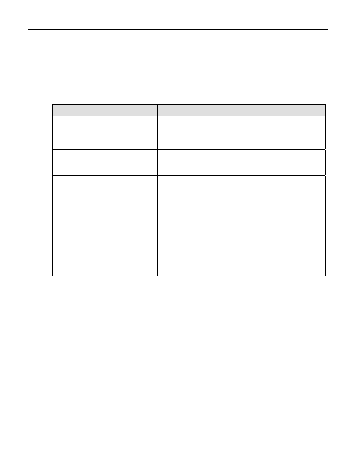
Step 1 - Enter the expected NOx and NO span gas concentrations:
Step Number Action Comment
1. Press
CAL-CONC-NOx
2. Press ENTR ENTR stores the expected NOx span value. This value will be
3. Press
CAL-CONC-NO
4. Press EXIT-EXIT Returns instrument to SAMPLE mode.
5. Press
SETUP-RNGEMODE-SING-ENTR
6. Press
SETUP-RNGE-SET
7. Press EXIT Returns instrument to SAMPLE mode.
This key sequence causes the M200A to prompt for the
expected NOx concentration. Enter the NOx span
concentration value by pressing the key under each digit until
the expected value is set.
used in the internal formulas to compute subsequent NOx
concentration values.
In the same CAL-CONC sub menu press the NO button and
enter the expected NO span value, then ENTR. As before this
value will be used in the internal formulas to compute the
subsequent NO concentration values.
If necessary you may want to change ranges. Normally the
instrument is shipped in single range mode set at 500 ppb. We
recommend doing the initial checkout on the 500 ppb range.
After SETUP-RNGE-SET, enter 500 and press ENTR. The
instrument will now be in the 500 ppb range.
2-7
PRINTED DOCUMENTS ARE UNCONTROLLED
Page 25
Teledyne API Model 200A NOX Analyzer Instruction Manual, 02246, Rev. G, DCN 5247
Step 2 - Calibrate the instrument:
Zero/Span Calibration Procedure
Step Number Action Comment
1. Input Zero gas Allow Zero gas to enter the sample port on the rear of the
instrument.
2. Press CAL The M200A enters the calibrate mode from sample mode.
3. Wait 10 min Wait for reading to stabilize at the zero value. If you wait less
than 10 minutes the final zero value may drift.
4. Press ZERO The ZERO button will be displayed.
5. Press ENTR Pressing ENTR actually changes the calculation equations and
zeroes the instrument.
6. Input Span Gas Switch gas streams to span gas.
7. Wait 10 min Wait for reading to stabilize at the span value. If you wait less
than 10 minutes the final span value may drift.
8. Press SPAN The SPAN button should be displayed. If it is not, check the
Troubleshooting Section 9.2.8 for instructions on how to
proceed. In certain circumstances at low span gas
concentrations (<100ppb), both the ZERO and SPAN buttons
will appear.
9. Press ENTR Pressing ENTR actually changes the calculation equations so
that the concentration displayed is the same as the expected
span concentration you entered above, thus spanning the
instrument.
10. Press EXIT Pressing EXIT returns the instrument to SAMPLE mode.
2-8
PRINTED DOCUMENTS ARE UNCONTROLLED
Page 26

Teledyne API Model 200A NOX Analyzer Instruction Manual, 02246, Rev. G, DCN 5247
Step 3 - Review the quality of the calibration:
Calibration Quality Check Procedure
Step Number Action Comment
1. Scroll the TEST
function menu until
the NO
displayed.
2. Scroll the TEST
function menu until
the NO SLOPE is
displayed.
3. Scroll the TEST
function menu until
the NOx OFFSET is
displayed.
4. Scroll the TEST
function menu until
the NO OFFSET is
displayed.
SLOPE is
x
The SLOPE value for NOx should be 1.0 ± 0.3. If the value is
not in this range, check Section 7.10 or 9. If the SLOPE value
is in the acceptable range, the instrum
optimally.
The SLOPE value for NO should be 1.0 ± 0.3. If the value is
not in this range, check Section 7.10 or 9. If the SLOPE is in
the acceptable range, the instrum
NOTE:
The NO and NOx slopes should be equal within ± 0.1.
The M200A will display the OFFSET parameter for the NOx
equation. This number should be near zero. A value of 0.0
± 150 mV indicates calibration in the optimal range. If the
OFFSET value is outside this range, check Section 7.4 or 9 for
procedures to correct the OFFSET value to near zero.
The instrument will now display the NO OFFSET value. It
should also have a value near zero (0.0 ± 150 mV).
ent will perform
ent will perform
optimally.
Step 4 - The M200A is now ready to measure sample gas.
2-9
PRINTED DOCUMENTS ARE UNCONTROLLED
Page 27
Teledyne API Model 200A NOX Analyzer Instruction Manual, 02246, Rev. G, DCN 5247
Table 2-2-4: Front Panel
2-10
PRINTED DOCUMENTS ARE UNCONTROLLED
Page 28
Teledyne API Model 200A NOX Analyzer Instruction Manual, 02246, Rev. G, DCN 5247
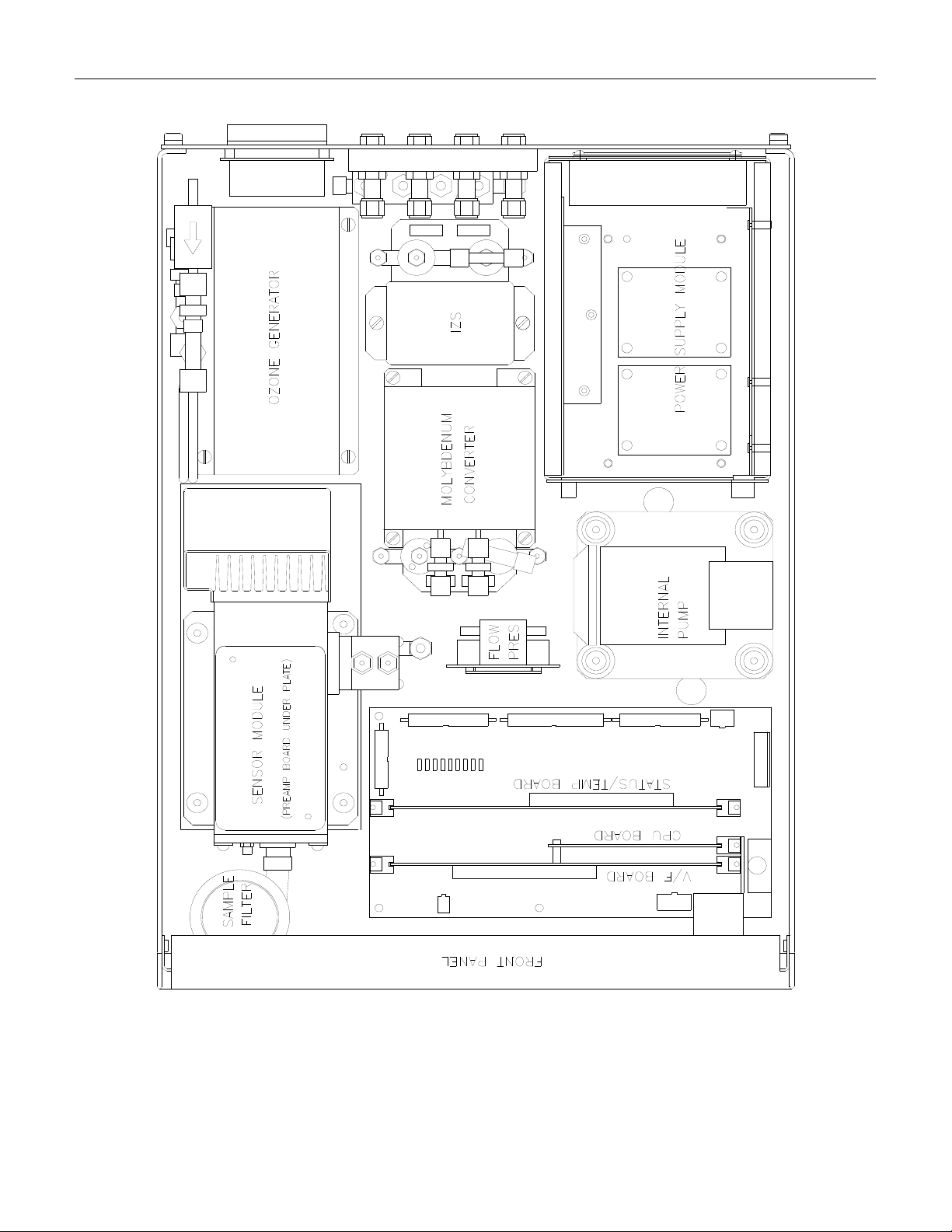
Table 2-2-5: Assembly Layout
2-11
PRINTED DOCUMENTS ARE UNCONTROLLED
Page 29
Teledyne API Model 200A NOX Analyzer Instruction Manual, 02246, Rev. G, DCN 5247
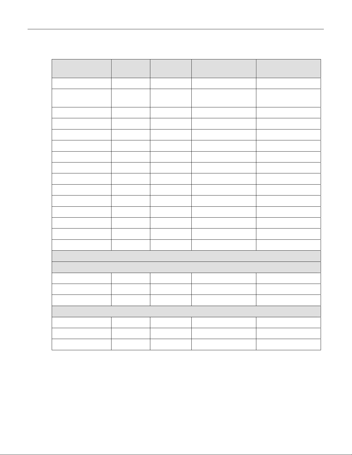
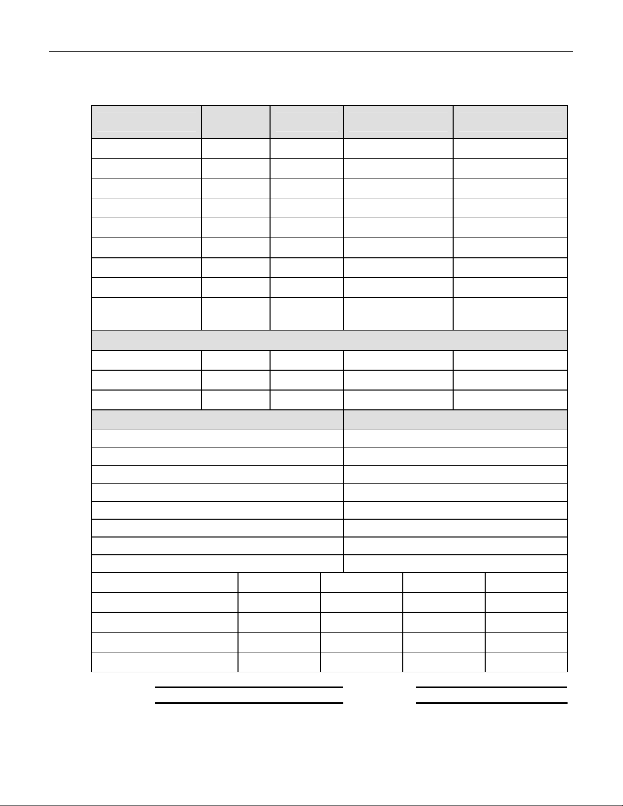
Table 2-2-6: Final Test and Calibration Values
Test Values
Observed
Value
Units Nominal Range Reference Section
RANGE PPB 50-20,000 5.3.4
STABILITY
(Zero Gas)
PPB < 0.2 9.1.1, Table 9-9-1,
9.2.5
SAMP FLW cc/min 500 ± 50 9.3.7, Table 9-9-1
OZONE FL cc/min 60 - 90 9.3.6, 9.3.7
PMT mV 0-5000 9.3.8.1, Table 9-9-1
AZERO mV -20 - 150 Table 9-9-1
HVPS V 450 - 900 constant 9.3.8.5
DCPS mV 2500 ± 200 9.3.5, 9.3.4
RCELL TEMP
BOX TEMP
PMT TEMP
IZS TEMP
MOLY TEMP
o
C 50 ±1 9.3.8.2
o
C 8-48 9.3.4.1
o
C 7 ± 1 9.3.8.4
o
C 50 ± 0.4 9.3.9
o
C 315 ± 5 9.3.4.1
RCEL PRES IN-Hg-A 4 - 10 constant 9.3.7
SAMP PRES IN-Hg-A 25 - 30 constant 9.3.7
Electric Test & Optic Test
Electric Test
PMT Volts mV 2000 ± 500 9.1.3.2
NO Conc PPB 1000 ± 250 9.1.3.2
NOx Conc PPB 1000 ± 250 9.1.3.2
Optic Test
PMT Volts mV 2000 ± 1000 9.1.3.3
NO Conc PPB 1000 ± 500 9.1.3.3
NOx Conc PPB 1000 ± 500 9.1.3.3
(table continued)
2-12
PRINTED DOCUMENTS ARE UNCONTROLLED
Page 30
Teledyne API Model 200A NOX Analyzer Instruction Manual, 02246, Rev. G, DCN 5247
Table 2-1: Final Test and Calibration Values (Continued)
Parameter
NO Span Conc PPB 20 - 20,000 Table 7-7-4
NOx Span Conc PPB 20 - 20,000 Table 7-7-4
NO Slope - 1.0 ± 0.3 Table 7-7-21
NOx Slope - 1.0 ± 0.3 Table 7-7-21
NO Offset mV -10 to +150 Table 7-7-21
NOx Offset mV -10 to +150 Table 7-7-21
Moly Efficiency % 0.96 - 1.02 7.8.6, 5.2.2.6
Stability at Zero PPB < 0.2 Table 9-9-1
Stability at Span PPB < 2 ppb @ 400ppb
Sample Flow cc/min 500 ± 50 9.3.7, Table 9-9-19
Ozone Flow cc/min 60 - 90 9.3.7, Table 9-9-19
IZS Purge Flow cc/min 60 ± 15 6.3
Observed
Value
Units Nominal Range Reference Section
Table 9-9-1
span gas
Measured Flows
Factory Installed Options Option Installed
Power Voltage/Frequency
Rack Mount, w/ Slides
Rack Mount, w/ Ears Only
Rack Mount, External Pump w/ Slides
Rack Mount, External Pump w/o Slides
Stainless Zero/Span Valves
Internal Zero/Span - IZS
Permeation Tube Output Specification
Current Loop - NOx Chan 4-20 mA 0-20 mA Isolated Non-Isolated
Current Loop - NO Chan 4-20 mA 0-20 mA Isolated Non-Isolated
Current Loop - NO2 Chan 4-20 mA 0-20 mA Isolated Non-Isolated
Current Loop - TST Chan 4-20 mA 0-20 mA Isolated Non-Isolated
Internal Pump
PROM # Serial #
Date Technician
2-13
PRINTED DOCUMENTS ARE UNCONTROLLED
Page 31

Teledyne API Model 200A NOX Analyzer Instruction Manual, 02246, Rev. G, DCN 5247
THIS PAGE IS INTENTIONALLY LEFT BLANK
2-14
PRINTED DOCUMENTS ARE UNCONTROLLED
Page 32

Teledyne API Model 200A NOX Analyzer Instruction Manual, 02246, Rev. G, DCN 5247
3 SPECIFICATIONS, AGENCY APPROVALS,
WARRANTY
3.1 Specifications
Ranges In 1ppb increments from 50ppb to 20,000ppb
Range Modes Single, Independent, AutoRange
Noise at Zero
Noise at Span
Lower Detectable Limit
Zero Drift
Zero Drift 1 ppb/7 days
Span Drift <0.5% FS/7 days
Lag Time 20 sec
Rise Time 95% in <60 sec
Fall Time 95% in <60 sec
Sample Flow Rate 500 cc/min. ± 10%
Linearity 1% of full scale
Precision 0.5% of reading
Temperature Range 5-40
Temp Coefficient < 0.1% per
Humidity 0-95% RH non-condensing
Voltage Coefficient < 0.1% per V
Dimensions HxWxD 7" x 17" x 23.6" (18cm x 43cm x 61cm)
Weight, Analyzer 43 lbs (20 kg) w/external pump
Weight, Analyzer 55 lbs (25 kg) w/internal pump
Weight, Ext Pump Pack 16 lbs (7 kg)
Weight, Internal Pump 5 lbs (2 kg)
Power, Analyzer
Power, Analyzer
Power, Ext Pump
Power, Ext Pump
Power, Int Pump 110 v/50/60 Hz, 60 watts
Environmental Installation Category (Over-voltage Category) II Pollution Degree 2
Recorder Output
Analog Resolution 1 part in 1024 of selected voltage or current range
Status Option 12 Status Outputs from opto-isolator
Measurement Units ppb, ppm, ug/m
1
0.2 ppb RMS
1
<0.5% of reading above 50 ppb
3
<0.5 ppb/24 hours
5
230 V ~ 50 Hz, 2.5A peak
5
4
2
0.4 ppb RMS
o
C
o
C
100 V ~ 50/60 Hz, 120V~ 60 Hz, 220 V~ 50 Hz, 240 V~ 50 Hz, 125 watts
110 V ~ 60 Hz, 220V~ 50 Hz, 240V~ 50Hz, 295 watts
230 V ~ 50 Hz, 2.5A peak
0-100 mV, 0-1, 5, 10v
3
, mg/m3
1. As defined by USEPA.
2. Defined as twice the zero noise level.
3. At constant temperature and voltage.
4. Bi-polar.
5. Electrical rating for CE Mark compliance.
3-1
PRINTED DOCUMENTS ARE UNCONTROLLED
Page 33

Teledyne API Model 200A NOX Analyzer Instruction Manual, 02246, Rev. G, DCN 5247
3.2 EPA Equivalency Designation
Advanced Pollution Instrumentation, Inc., Model 200A Nitrogen Oxides Analyzer is designated
as Reference Method Number RFNA-1194-099 as defined in 40 CFR Part 53, when operated
under the following conditions:
1. Range: Any range from 50 parts per billion (ppb) to 1 ppm.
o
2. Ambient temperature range of 5 to 40
3. Line voltage range of 105-125 VAC, 60Hz; 220-240 VAC, 50Hz.
4. With 5-micron TFE filter element installed in the internal filter assembly.
5. Sample flow of 500 ± 50 cc/min.
6. Vacuum pump (internal or external) capable of 10"Hg Abs pressure @ 2 slpm or better.
7. Software settings:
A. Dynamic span OFF
B. Dynamic zero OFF
C. Cal-on-NO2 OFF
D. Dilution factor OFF
E. AutoCal ON or OFF
F. Independent range ON or OFF
G. Autorange ON or OFF
H. Temp/Pres compensation ON
I. Converter Eff. Acceptable values of 0.96 to 1.02
C.
Under the designation, the Analyzer may be operated with or without the following options:
1. Rack mount with slides.
2. Rack mount without slides, ears only.
3. Rack mount for external pump w/o tray.
4. Stainless steel zero/span valves.
5. Internal zero/span.
6. NO
7. NO
8. NO
9. NO
permeation tube - uncertified 0.4ppm @ 0.7 lpm.
2
permeation tube - certified 0.4ppm @ 0.7 lpm.
2
permeation tube - certified 0.8ppm @ 0.7 lpm.
2
permeation tube - uncertified 0.8ppm @ 0.7 lpm.
2
10. 4-20mA, isolated outputs.
11. Status outputs.
12. RS-232 output.
13. Internal pump or external pump.
14. 1 micron sample filter.
3-2
PRINTED DOCUMENTS ARE UNCONTROLLED
Page 34

Teledyne API Model 200A NOX Analyzer Instruction Manual, 02246, Rev. G, DCN 5247
3.3 Warranty
ADVANCED POLLUTION INSTRUMENTATION DIVISION
Prior to shipment, T-API equipment is thoroughly inspected and tested. Should equipment failure occur,
T-API assures its customers that prompt service and support will be available.
COVERAGE
After the warranty period and throughout the equipment lifetime, T-API stands ready to provide on-site
or in-plant service at reasonable rates similar to those of other manufacturers in the industry. All
maintenance and the first level of field troubleshooting is to be performed by the customer.
NON-API MANUFACTURED EQUIPMENT
Equipment provided but not manufactured by T-API is warranted and will be repaired to the extent and
according to the current terms and conditions of the respective equipment manufacturers warranty.
GENERAL
During the warranty period, T-API warrants each Product manufactured by T-API to be free from
defects in material and workmanship under normal use and service. Expendable parts are excluded.
(T-API) (02024D) (DCN 4473)
If a Product fails to conform to its specifications within the warranty period, API shall correct such
defect by, in API's discretion, repairing or replacing such defective Product or refunding the purchase
price of such Product.
The warranties set forth in this section shall be of no force or effect with respect to any Product: (i) that
has been altered or subjected to misuse, negligence or accident, or (ii) that has been used in any manner
other than in accordance with the instruction provided by T-API, or (iii) not properly maintained.
THE WARRANTIES SET FORTH IN THIS SECTION AND THE REMEDIES THEREFORE
ARE EXCLUSIVE AND IN LIEU OF ANY IMPLIED WARRANTIES OF MERCHANTABILITY,
FITNESS FOR PARTICULAR PURPOSE OR OTHER WARRANTY OF QUALITY,
WHETHER EXPRESSED OR IMPLIED. THE REMEDIES SET FORTH IN THIS SECTION
ARE THE EXCLUSIVE REMEDIES FOR BREACH OF ANY WARRANTY CONTAINED
HEREIN. API SHALL NOT BE LIABLE FOR ANY INCIDENTAL OR CONSEQUENTIAL
DAMAGES ARISING OUT OF OR RELATED TO THIS AGREEMENT OF T-API'S
PERFORMANCE HEREUNDER, WHETHER FOR BREACH OF WARRANTY OR
OTHERWISE.
3-3
PRINTED DOCUMENTS ARE UNCONTROLLED
Page 35

Teledyne API Model 200A NOX Analyzer Instruction Manual, 02246, Rev. G, DCN 5247
TERMS AND CONDITIONS
All units or components returned to Teledyne API should be properly packed for handling and
returned freight prepaid to the nearest designated Service Center. After the repair, the
equipment will be return e d , f r e i g h t p r e p a i d .
3-4
PRINTED DOCUMENTS ARE UNCONTROLLED
Page 36

Teledyne API Model 200A NOX Analyzer Instruction Manual, 02246, Rev. G, DCN 5247
4 THE M200A NOX ANALYZER
4.1 Principle of Operation
The Teledyne API Model 200A Analyzer is designed to measure the concentration of nitric
oxide [NO], total oxides of nitrogen [NOX] and, by calculation, nitrogen dioxide [NO2]. The
instrument measures the light intensity of the chemiluminescent gas phase reaction of nitric
oxide [NO] and ozone [O3] as follows:
223 O*NOONO
hvNO*NO 22
The reaction of NO with ozone results in electronically excited NO2 molecules as shown in the
first equation above. The excited NO2 molecules release their excess energy by emitting a
photon and dropping to a lower energy level as shown in the second equation. It has been shown
that the light intensity produced is directly proportional to the [NO] concentration present.
The Analyzer samples the gas stream and measures the [NO] concentration by digitizing the
signal from the Analyzer's photomultiplier tube (PMT). A valve then routes the sample stream
through a converter containing heated molybdenum to reduce any NO2 present to NO by the
following reaction:
315o C
32 MoONO3MoNO3
The Analyzer now measures the total NOx concentration. The [NOx] and [NO] values are
subtracted from each other by the built-in computer yielding the [NO2] concentration. The three
results [NO], [NO
several instantaneous and long term averages of all three components. These readings are also
stored internally in the M200A’s data acquisition system (DAS).
The software uses an adaptive filter to accomodate rapid changes in concentration. The
algorithm monitors the rate of change in concentration for both the NO and NOx channels. When
a change in concentration is detected, the software changes the sample filters to rapidly respond
to the change. The filters are adjusted to minimize the errors introduced by the time delay
between the NOx and NO channel measurements; this assures accurate NO2 measurements.
When the rate of change decreases, the filters are lengthened to provide good signal/noise ratio.
The parameters used to operate the adaptive filter have been tuned to match the electrical and
pneumatic characteristics of the M200A.
], and [NO2] are then further processed and stored by the computer yielding
x
4-1
PRINTED DOCUMENTS ARE UNCONTROLLED
Page 37

Teledyne API Model 200A NOX Analyzer Instruction Manual, 02246, Rev. G, DCN 5247
Table 4-4-1: Block Diagram
4-2
PRINTED DOCUMENTS ARE UNCONTROLLED
Page 38

Teledyne API Model 200A NOX Analyzer Instruction Manual, 02246, Rev. G, DCN 5247
4.2 Operation Summary
4.2.1 Sensor Module, Reaction Cell, Detector
The sensor module (Table 9-9-20) is where the chemiluminescent reaction takes place and where
the light from the reaction is detected. It is the most complicated and critical sub-assembly in the
entire analyzer. It consists of the following sub-assemblies and functions:
1. The reaction cell and flow control module
2. Reaction cell heater/thermistor
3. Photo multiplier tube(PMT) and high voltage power supply
4. PMT cooler/cold block/heatsink/fan
5. Preamp assembly:
A. Preamp range control hardware
B. HVPS control
C. PMT cooler temp control
D. Electric test electronics
E. Optic test electronics
4.2.2 Pneumatic Sensor Board
The sensor board consists of two pressure sensors and a flow sensor. One pressure sensor
measures the pressure in the reaction cell,which is maintained at about one-quarter of
atmospheric pressure. The second pressure sensor measures the pressure just upstream of the
reaction cell, which is near ambient pressure. From these two pressures the sample flow rate can
be computed and is displayed as sample flow in the TEST menu. Finally, a solid state flow meter
measures the ozone flow directly. Likewise, it is displayed as a TEST function.
The M200A displays all pressures in inches of mercury-absolute (in-Hg-A). Absolute pressure is
the reading referenced to a vacuum or zero absolute pressure. This method was chosen so that
ambiguities of pressure relative to ambient pressure can be avoided.
For example, if the vacuum reading is 25" Hg relative to room pressure at sea level the absolute
pressure would be 5" Hg. If the same absolute pressure was observed at 5000 ft altitude where
the atmospheric pressure was 5" lower, the relative pressure would drop to 20" Hg, however the
absolute pressure would remain the same 5" Hg-A.
4-3
PRINTED DOCUMENTS ARE UNCONTROLLED
Page 39

Teledyne API Model 200A NOX Analyzer Instruction Manual, 02246, Rev. G, DCN 5247
4.2.3 Computer Hardware and Software
CPU Board
The M200A Analyzer is operated by an NEC V40 microprocessor. Computer communication is
done via 2 major hardware assemblies, the V/F board and the front panel display/keyboard. The
computer's multitasking operating system allows it to control the instrument, monitor test points,
generate analog outputs and provide a user interface via the display, keyboard and RS-232 port.
These operations appear to be happening simultaneously but are actually done sequentially based
on a priority queuing system maintained by the operating system. The jobs are queued for
execution only when needed, therefore the system is very efficient with computer resources. The
M200A is a true computer based instrument. The microprocessor does most of the instrument
control functions such as valve switching and temperature control. Data collection and
processing are done entirely in the CPU with the final concentration values being sent to a D/A
converter to produce the instrument analog output.
The computer memory is divided into 3 sections: ROM memory contains the multi-tasking
operating system code plus the instructions that run the instrument. The RAM memory is used to
hold temporary variables and current concentration data. The EEPROM memory contains the
instrument set-up variables such as range and instrument ID number. The EEPROM data is nonvolatile so the instrument can lose power and the current set-up information is preserved.
4.2.4 V/F Board
The V/F board is multifunctional, consisting of A/D input channels, digital I/O channels, and
analog output channels. Communication with the computer is via a STD bus interface. The
computer receives all of the instrument data and provides all control functions through the V/F
board.
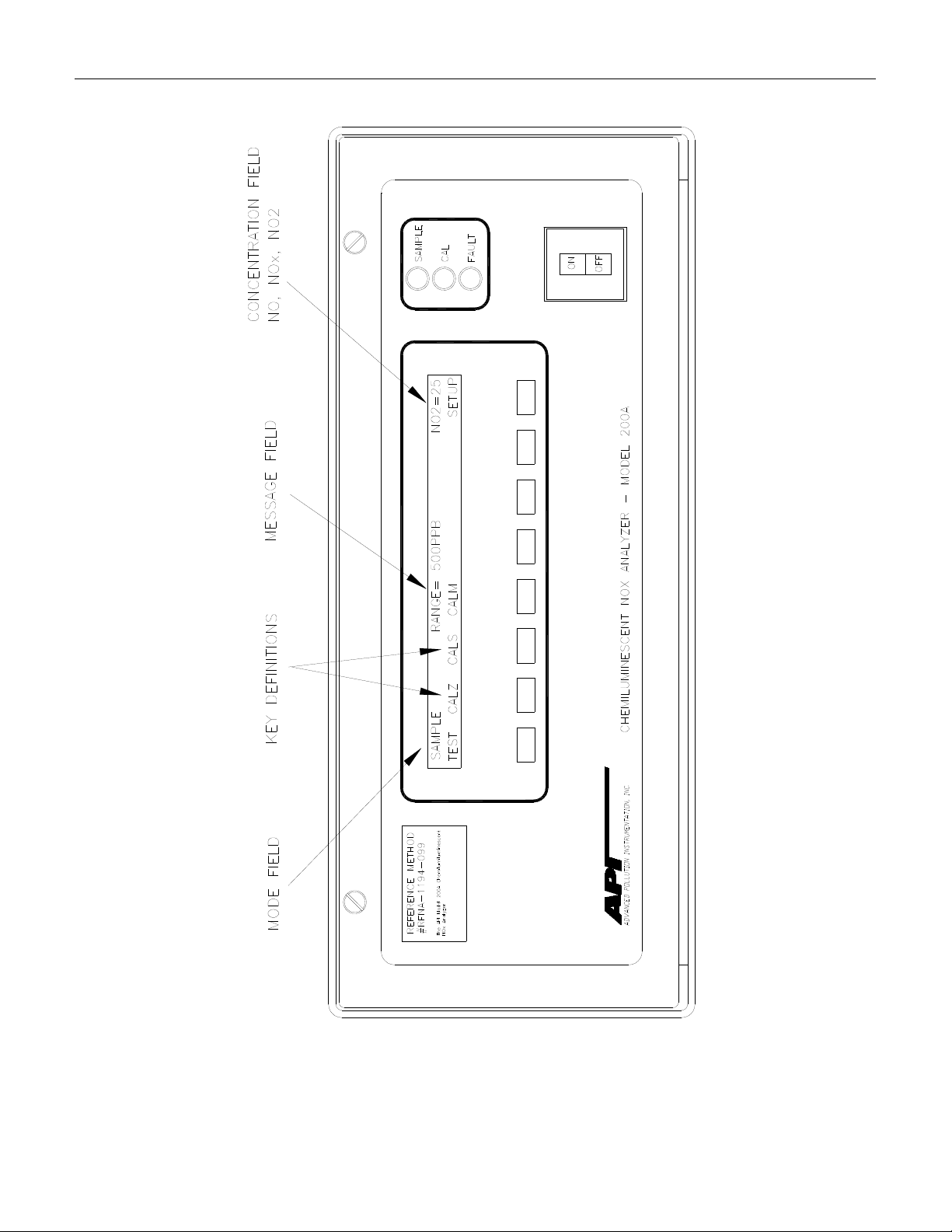
4.2.5 Front Panel
The front panel of the M200A is shown in Table 2-2-4. The front panel consists of a 2 line
display and keyboard, 3 status LED's and power switch. Communication with the display,
keyboard, and status LED's is done via the computer's on-board parallel port. The M200A was
designed as a computer controlled instrument, therefore all major operations can be controlled
from the front panel display and keyboard.
The display consists of 2 lines of 40 characters each. The top line is divided into 3 fields, and
displays information. The first field is the mode field. A list of operating modes is given in
Table 5-5-9.
4-4
PRINTED DOCUMENTS ARE UNCONTROLLED
Page 40

Teledyne API Model 200A NOX Analyzer Instruction Manual, 02246, Rev. G, DCN 5247
The center field displays TEST values. The TEST functions allow you to quickly access many
important internal operating parameters of the M200A. This provides a quick check on the
internal health of the instrument. The right hand field shows current concentration values of NO,
NOx, and NO2. The display scrolls between the 3 values every 4 seconds.
4.2.5.1 Keyboard
The second line of the display contains eight fields. Each field defines the key immediately
below it. By redefining the keys dynamically it is possible to simplify the instrument electronics
and user interface.
When entering data in the keyboard, if the entered value is not accepted, the M200A will "beep"
to notify the user that the value keyed in was not accepted. The original value remains
unchanged.
4.2.5.2 Status LED's
At the right of the display there are 3 status LED's. They can be in three states, OFF, ON, and
Blinking. The meanings of the LED's are given in Table 4-4-2.
Table 4-4-2: Front Panel Status LED's
LED State Meaning
Green On
Off
Blinking
Yellow
Red Off
(1) This occurs during Calibration, DAS holdoff, power-up holdoff, and when in Diagnostic mode.
Off
On
Blinking
Blinking
Monitoring normally, taking DAS data
NOT monitoring, DAS disabled
Monitoring, DAS in HOLDOFF mode (1)
Auto cal. disabled
Auto/Dynamic cal. enabled
Calibrating
No warnings exist
Warnings exist
4.2.5.3 Power Switch
The power switch has two functions. The rocker switch controls overall power to the instrument,
in addition is a circuit breaker. If attempts to power up the M200A result in a circuit breaker trip,
the switch automatically returns to the off position, and the instrument will not power up.
4-5
PRINTED DOCUMENTS ARE UNCONTROLLED
Page 41

Teledyne API Model 200A NOX Analyzer Instruction Manual, 02246, Rev. G, DCN 5247
4.2.6 Power Supply Module
The Power supply module supplies AC and DC power to the rest of the instrument. It consists of
a four output linear DC power supply and a 15 volt switching supply. In addition, it contains the
switching circuitry to drive the DC operated valves and several switched AC loads that operate
the Rx cell, IZS, and molybdenum converter heaters and the ozone generator. The only voltages
not generated in the PSM are the high voltage DC required by the PMT which is generated
inside the sensor module and the high voltage AC used by the ozone generator.
4.2.7 Pump, Valves, Pneumatic System
A standard M200A comes with two valves. The NO/NOx valve switches sample gas into the
reaction cell from either the sample inlet port or from the moly converter into the reaction cell.
Periodically, the AutoZero valve shuts off sample flow to the reaction cell to measure the
detector dark signal.
A catalytic scrubber contained in the moly converter assembly removes the ozone present in the
exhaust stream.
If the external pump is selected, This option is not available with the internal pump.
The external Pump Pack includes a vacuum pump and optional charcoal NO2 scrubber. By using
this pump, it is possible to remove a significant source of acoustic noise and vibration from the
immediate area of the analyzer. The pump pack is supplied with 0.25" tube fitting to connect to
the exhaust fitting on the M200A rear panel. See Table 2-2-3 for hook-up information. Plugging
the power cord into an AC outlet turns on the pump pack, see Table 4-4-3.
The internal pump has slightly lower performance specifications, and shorter MTBF, however it
consumes significantly less power, and makes an instrument that has a single chassis. The NO2
scrubber option.
A pump is supplied as standard equipment, however if another pump is used, it must have the
following characteristics:
1. The pump must supply 1 slpm at 5"Hg-A.
2. The ozone scrubber must remove all ozone from the analyzer exhaust.
3. Connect the exhaust (Table 2-2-3) to a pump with <3 m of 1/4" PTFE tubing.
Failure to meet the performance specifications will result in poor analyzer perform
to the pump, damage to the analyzer, and may jeopardize warranty repairs. Teledyne API
strongly recommends that the factory supplied pump be used with the M200A.
ance, damage
4-6
PRINTED DOCUMENTS ARE UNCONTROLLED
Page 42

Teledyne API Model 200A NOX Analyzer Instruction Manual, 02246, Rev. G, DCN 5247
NOTE
On vacuum vs absolute pressure:
Many vacuum gauges read relative to ambient pressure, therefore
a reading of 25" of mercury (Hg) at sea level (which would give an
absolute pressure of about 5" Hg in the reaction cell) would read
only 20" Hg at high altitude sites. Therefore in this manual the vacuum
specification of 5" Hg pressure is given as an absolute pressure
- 5"Hg-A - reference against zero absolute pressure (a perfect vacuum)
thus removing ambiguities for high altitude sites.
4-7
PRINTED DOCUMENTS ARE UNCONTROLLED
Page 43

Teledyne API Model 200A NOX Analyzer Instruction Manual, 02246, Rev. G, DCN 5247
Table 4-4-3: External Pump Pack
4-8
PRINTED DOCUMENTS ARE UNCONTROLLED
Page 44

Teledyne API Model 200A NOX Analyzer Instruction Manual, 02246, Rev. G, DCN 5247
4.2.8 Ozone Generator
Because of the instability of ozone, it is necessary to generate this gas inside the analyzer. The
ozone generation module consists of a high voltage AC supply and silent discharge tube and
permeation type air drier. A complete description of its function and service requirements can be
found in Section 9.3.6.
CAUTION
Lethal voltages present inside ozone generator.
Do not defeat electrical interlock.
The dry air supply for the ozone generator uses a membrane drier to supply air with a dew point
of 0o C or less. The exhaust side of the membrane is connected to the vacuum manifold at the
rear of the instrument.
Normal room air contains enough water vapor to damage the generator and components
downstream. To prevent damage, the generator will be turned ON after 30 min following a cold
start. Otherwise, the starting of the generator will follow the table below:
Table 4-4-4: Ozone Generator Start-up Timing
Ozone Gen State at
Power-On
ON If instrument has been off for less than 30 min
OFF If instrument has been off for more than 30 min
Instrument Action
4.2.9 Molydbenum Converter
The molybdenum converter is a stainless steel cartridge containing molybdenum chips heated to
315 C. The converter's function is to reduce nitrogen dioxide NO2 to nitric oxide NO. The
temperature control for this module is done by the computer.
4-9
PRINTED DOCUMENTS ARE UNCONTROLLED
Page 45

Teledyne API Model 200A NOX Analyzer Instruction Manual, 02246, Rev. G, DCN 5247
THIS PAGE IS INTENTIONALLY LEFT BLANK
4-10
PRINTED DOCUMENTS ARE UNCONTROLLED
Page 46

Teledyne API Model 200A NOX Analyzer Instruction Manual, 02246, Rev. G, DCN 5247
5 SOFTWARE FEATURES
The M200A control software has two major operating modes. The SAMPLE mode is the normal
mode when the instrument is taking data. The software menu that covers the SAMPLE mode is
diagrammed in Table 5-5-1.
When the instrument is initially installed, or problems indicate a need for diagnostics, the
SETUP menu is used. The SETUP menu is diagrammed in Table 5-5-2.
5.1 Index To Front Panel Menus
The next several pages contain two different styles of indexes that will allow you to navigate the
M200A software menus. The first two pages show a "tree" menu structure to let you see at a
glance where each software feature is located in the menu. The second menu contains a brief
description of each key mnemonic and a reference to the section of the manual that describes its
purpose and function in detail.
5-1
PRINTED DOCUMENTS ARE UNCONTROLLED
Page 47

Teledyne API Model 200A NOX Analyzer Instruction Manual, 02246, Rev. G, DCN 5247
Table 5-5-1: Sample Menu Tree
5-2
PRINTED DOCUMENTS ARE UNCONTROLLED
Page 48

Teledyne API Model 200A NOX Analyzer Instruction Manual, 02246, Rev. G, DCN 5247
Table 5-5-2: Setup Menu Tree
5-3
PRINTED DOCUMENTS ARE UNCONTROLLED
Page 49

Teledyne API Model 200A NOX Analyzer Instruction Manual, 02246, Rev. G, DCN 5247
5.1.1 Sample Menu
Table 5-5-3: M200A Sample Menu Structure
Menu Level
Level 1 Level 2 Level 3 Level 4 Description
TEST
TST>
CAL Zero/Span calibration w/ gas
CALZ Zero calibration w/ zero gas
CALS Span calibration w/ span gas
ZERO Press ZERO then ENTR will
SPAN Press SPAN then ENTR will
CONC Expected NO/ NOx span
NOX
NO CONC Enter expected NO span
CONV Sub-menu for converter
NO2 Expected NO2 concentration for
CAL Automatic converter efficiency
SET Set the converter efficiency
MSG Displays warning messages 9.1.2
CLR Clears warning messages 9.1.2
SETUP The SETUP Menu - See next
Test functions
through sample port
from zero valve option or IZS
option
from span valve option or IZS
option
zero analyzer
span analyzer
concentrations and Moly conv.
efficiency setup
CONC
Enter expected
concentration
concentration
efficiency setup and
verification
converter efficiency calculation
calibration and entry
manually
table below
NO
span
x
Reference
Section
5.2.1,
9-1
5.2.2.1, 7.3
5.2.2.2, 7.1, 7.2
5.2.2.3, 7.1, 7.2
5.2.2.2, 7.1, 7.2
5.2.2.3, 7.1, 7.2
Table 7-7-4
5.2.2, Table 77-4
5.2.2, Table 77-4
5.2.2.6, 7.8.6
5.2.2.6, 7.8.6
5.2.2.6, 7.8.6
5.2.2.6, 7.8.6
Table 5-5-4
Table 9-
5-4
PRINTED DOCUMENTS ARE UNCONTROLLED
Page 50

Teledyne API Model 200A NOX Analyzer Instruction Manual, 02246, Rev. G, DCN 5247
5.1.2 Set-Up Menu
Table 5-5-4: M200A Setup Menu Structure
Setup Menu #1
Level 1 Level 2 Level 3 Level 4 Description
CFG CFG is primarily used for
showing special
configuration options and
factory special software
PREV,
NEXT, LIST
AUTOCAL Automatic span check or
SEQUENCE Selects Sequence 5.3.2, 6.4
PREV-
MODE Selects mode of calibration
SET For a given Sequence and
DAS Data Acquisition
VIEW Select which DAS data
PREV-
EDIT PREV Move down the DAS data
PREV10 Move down 10 entries in the
NEXT Move up the DAS data buffer
NEXT10 Move up 10 entries in the
PREV, NEXT can be used to
scroll through the
configuration list. LIST
automatically scrolls the list
calibration
Scrolls display to select
NEXT
Scroll through data collectors
NEXT
calibration sequence 1, 2, or
3
(zero, span, zero-span) plus
disable
Mode, sets timing and
calibration attributes
System(DAS) - keeps 1 to
1500 minute averages of data
collector to view
CONC, PNUMTC, CAL
DAT. The DAS data
structure can be viewed as a
list with the most recent data
at the top. The pointer is
initialized at the top - the
most recent entry.
buffer to examine older data
DAS data buffer
to display more recent data
DAS data buffer
Reference
Section
5.3.1
5.3.1
5.3.2, 6.4
5.3.2, 6.4
5.3.2, 6.4
5.3.2, 6.4
5.3.3
5.3.3
5.3.3
5.3.3
5.3.3
5.3.3
5.3.3
5-5
PRINTED DOCUMENTS ARE UNCONTROLLED
Page 51

Teledyne API Model 200A NOX Analyzer Instruction Manual, 02246, Rev. G, DCN 5247
Table 5-5-5: M200A Menu Structure - Setup Menu #2
Setup Menu #2
Level 1 Level 2 Level 3 Level 4 Description
RANGE Range control menu 5.3.4
MODE Range mode select – Single,
Autorange, Independent
SET Sets range if mode is Single
range
NO Sets NO concentration if indep
ranges enabled
NOx
NO2 Sets NO2 concentration if indep
LO Sets low range if Autorange
HI Sets high range if Autorange
UNITS Unit selection menu 5.3.4.5
PPB,PPM,
UGM,
MGM
DIL Enter dilution factor if
PASS Password enable/disable menu 5.3.5
ON-OFF Enable/disable password
CLOCK TIME Adjusts time on the internal
DATE Adjusts date on the internal
MORE Continue menus on next level
COMM RS-232 communications
BAUD Sets the BAUD rate to 300 -
ID Sets the instrument ID -
Select units that instrument uses 5.3.4.5
NO
Sets
ranges enabled
ranges enabled
enabled
enabled
connected to stack dilution
probe
checking
time of day clock
time of day clock
down
control menu
19,200
(included on all RS-232
messages)
concentration if indep
x
Reference
Section
5.3.4
5.3.4.1
5.3.4.3
5.3.4.3
5.3.4.3
5.3.4.2
5.3.4.2
5.3.4.4
5.3.5
5.3.6
5.3.6
Table 5-5-4
5.3.8, 5.5
5.3.8, 5.5
5.3.8, 5.5
Table 5-5-6: M200A Menu Structure - Setup Menu #3
5-6
PRINTED DOCUMENTS ARE UNCONTROLLED
Page 52

Teledyne API Model 200A NOX Analyzer Instruction Manual, 02246, Rev. G, DCN 5247
Setup Menu #3
Level 1 Level 2 Level 3 Level 4 Description
VARS Internal variables 5.3.9, 9.2
PREV,
NEXT,
JUMP,
EDIT
DIAG Diagnostic menu 5.3.7, 9
PREV,
NEXT
SIG I/O Examines, changes analog and
ANALOG
D/A CAL Calibrates analog outputs 9.1.3.6
OPTIC
ELEC
O3 GEN Turns OFF/ON ozone generator 9.1.3.4
RS-232 Writes test data to RS-232 port 9.1.3.7
PREV, NEXT scroll up and
down through the VARS menu.
JUMP will go to variable
number selected, EDIT will
allow editing of the selected
variable
PREV, NEXT scroll up and
down through the DIAG menu
digital internal signals
Writes test voltages to analog
OUT
TEST
TEST
outputs
Activates Optic Test feature 9.1.3.3
Activates Electric Test feature 9.1.3.2
Reference
Section
5.3.9, 9.2
5.3.7, 9
9.1.3.1
9.1.3.5
5-7
PRINTED DOCUMENTS ARE UNCONTROLLED
Page 53

Teledyne API Model 200A NOX Analyzer Instruction Manual, 02246, Rev. G, DCN 5247
5.2 Sample Mode
The M200A software has two major operating modes, the SAMPLE mode and the SETUP mode.
The SAMPLE mode is the normal mode when the instrument is taking data. The SETUP mode is
used when the instrument is initially installed, or when problems indicate a need for diagnostics.
One of the features of the SAMPLE mode is TEST functions. The TEST functions can be
examined while the instrument is taking data, and can be used to determine if the instrument is
set up and functioning properly.
Section 5.2.1 defines each TEST function and explains its use.
5.2.1 Test Functions
NOTE
In any of the following TEST functions, if a value of
XXXX is displayed, that indicates an off scale and
therefore meaningless reading.
To use the TEST functions to diagnose instrument faults, refer to Troubleshooting Section 9.1.
Range
The M200A can operate in one of three range modes:
1. In single range mode there is one range for all 3 outputs. This is the default range mode.
2. Independent range mode allows different ranges for each output. When enabled, there are
three range values displayed, NO, NOx and NO2.
3. Auto range mode allows a low range and high range. The M200A will automatically
switch to the other range dynamically as concentration values require. The TEST values will
show the range the instrument is currently operating in, and will dynamically display the
alternate range as the range changes occur.
NOTE
Each of the range modes Single range, Autorange, and
Independent ranges are mutually exclusive.
5-8
PRINTED DOCUMENTS ARE UNCONTROLLED
Page 54

Teledyne API Model 200A NOX Analyzer Instruction Manual, 02246, Rev. G, DCN 5247
Stability
The instrument noise is computed using the standard deviation of the last 10 minutes of data,
with the value being computed at the end of each NO/ NO
cycle. It is computed for the NOx
x
channel only. The value only becomes meaningful if sampling a constant concentration for more
than 20 minutes, so the various software filters can stabilize. The value shown should be
compared to the value observed in Table 2-2-6.
Sample Flow
The SAMPLE FLOW test function is com
puted from the pressure measured up-stream of the
sample flow orifice. The pressure down-stream of the orifice is also checked to assure the
assumptions of the equation are valid. SAMPLE FLOW will indicate variations in flow caused
by changes in atmospheric pressure, but will not detect a plugged sample flow orifice. The
nominal value is 500 ± 50 cc/min.
Ozone Flow
The OZONE FLOW test function is directly measured by a solid state flow meter. Variations in
this value indicate variations in ozone flow. The nominal value for ozone flow is 60 - 90 cc/min.
PMT Voltage
The PMT VOLTAGE shows the PMT signal at the output of the preamp board. The waveform
of the PMT voltage can be complex, and vary from near 0 mV when zero gas is in the reaction
cell to 5000 mV when a high concentration of NOx is being measured. If the PMT reading is
consistently 5000 mV, that indicates an off-scale reading. Typical readings bounce around,
which is normal.
Normalized PMT Voltage
Like the PMT Voltage TEST function above, the NORMALIZED PMT VOLTAGE measures
the PMT signal at the output of the preamp board. The difference here is that several
normalization functions are applied to this signal before it is displayed. The most important is the
temperature and pressure compensation factors. If NORM PMT is used as suggested in the
Factory Calibration Procedure (Section 9.1.6) the M200A will be correctly calibrated.
AZERO Voltage
This test measurement is the AUTOZERO voltage. It indicates the most recent reading from the
AutoZero circuit. The units are mV and from – 20 to 150 are acceptable.
5-9
PRINTED DOCUMENTS ARE UNCONTROLLED
Page 55

Teledyne API Model 200A NOX Analyzer Instruction Manual, 02246, Rev. G, DCN 5247
High Voltage Power Supply (HVPS)
The HVPS reading is a measure of the scaled-up HVPS programming voltage. The voltage used
to set the HVPS output is generated on the Preamp board. Its value is between 0 and 1 volt,
corresponding to a voltage of 0 to 1000 volts out of the HVPS. The HVPS front panel TEST
measurement should be greater than 450 volts and will typically be around 600-800V.
DC Power Supply (DCPS)
The DCPS voltage is a composite of the 5 and ± 15 VDC voltages in the Power Supply Module.
This is meant to be a quick indicator to show if the PSM is working correctly. The nominal value
is 2500 mV ± 200 mV.
Reaction Cell Temperature
This is a measurement of the temperature of the reaction cell. It is controlled by the computer to
50 ± 1 C. Temperatures outside this range will cause the M200A output to drift.
Box Temperature
This TEST function shows the temperature inside the chassis of the M200A. The temperature
sensor is located on the Status/Temp Board. Typically it runs 2 to 10 C higher than the ambient
temperature. The M200A has been engineered to maintain stable output over 5 to 40 C ambient
temperature range.
PMT Temperature
The temperature of the PMT is closely controlled by a dedicated proportional temperature
controller. The nominal set-point is 7 ± 1 C. Readings outside this range will cause instrument
drift due to gain changes in the PMT detector.
IZS Temperature
The IZS option has an oven for NO
permeation tubes. The oven temperature is nominally 50 C.
2
The permeation tube temperature is stable to ± 0.1 C, although it is normal to see the
temperature on the front panel move ± 0.4 C due to the proximity of the temp sensor to the
heater. It can be adjusted from the front panel by pressing SETUP-MORE-VARS and selecting
the IZS_SET item and entering the desired temperature. Using this adjustment, the permeation
rate of the NO
permeation tube can be adjusted to a desired value. See Section 6.3 for
2
information on adjusting the IZS temperature.
5-10
PRINTED DOCUMENTS ARE UNCONTROLLED
Page 56

Teledyne API Model 200A NOX Analyzer Instruction Manual, 02246, Rev. G, DCN 5247
Moly Temperature
The moly temperature is controlled by the computer. The nominal set-point is 315 ± 5 C. The
temperature sensor inside the moly is a type-J thermocouple. The thermocouple amplifier is
located on the STATUS/TEMP board. If the thermocouple breaks, the reading will go to 500 C
and turn off power to the heater.
Reaction Cell Pressure
The pressure in the reaction cell is measured by a solid state pressure sensor which measures
absolute pressure. Absolute pressure was chosen because it is an unambiguous measure of cell
pressure. This pressure will vary depending on several things.
1. The type of pump attached to the analyzer.
2. Variations in local weather will cause a ± 0.3in-Hg change in pressure.
3. The altitude of the analyzer will cause the cell pressure to change.
Nominal values are 3 to 10 in-Hg-A. Typical readings are about 5 in-Hg-A for the external
pump, and about 8 in-Hg-A or better for the internal pump.
Sample Pressure
The pressure in the sample inlet line is measured by a solid state pressure sensor which measures
absolute pressure. Absolute pressure was chosen because it is an unambiguous measure of
sample pressure. This pressure typically runs 0.5" or so below atmospheric pressure due to the
pressure drop in the sample inlet lines.
NOx, NO Slope and Offset Values
The coefficients of two (NOx and NO) straight line equations determine the calibration of the
M200A. The values of these parameters can be used to determine the quality of the calibration.
These 4 parameters contain valuable information about the quality and validity of the calibration.
Refer to Section 5.2.2.5 for more information on the formulas. Refer to Section 7.10 Calibration
Quality for details on how to use these values.
Time
This is an output of the M200A'
s internal time of day clock.
5-11
PRINTED DOCUMENTS ARE UNCONTROLLED
Page 57

Teledyne API Model 200A NOX Analyzer Instruction Manual, 02246, Rev. G, DCN 5247
5.2.2 CAL, CALS, CALZ, Calibration Functions
The calibration and zero/span checking of the M200A analyzer is treated in detail in Section 7,
Table 7-7-1 summarizes types of calibration. The basic function of each of these keys is
described here.
5.2.2.1 CAL, CALS, CALZ
The above keys control the calibration functions of the analyzer. In the CAL mode the analyzer
can be calibrated with zero/span gas coming in through the sample input port on the rear panel. If
the analyzer is equipped with the IZS option, or Zero/Span valves, there will be CALZ and
CALS buttons also. These buttons operate the Zero/Span valves or IZS system. The setup of
these options is covered in Section 6.3, and their operation is explained in Section 7.
5.2.2.2 Zero
Pressing the ZERO key along with ENTR will cause the instrument to adjust the OFFSET value
of the internal form
over a limited range of signal levels, therefore the signal does not have to be exactly zero for the
instrument to be zeroed. The instrument will not, however, allow a zero cal on any signal level,
therefore it is not possible to zero the instrument with span gas in the reaction cell. If the ZERO
key does not come on as expected, check Section 9.2.9.
ula so that the instrument reads zero. The M200A allows zero adjustment
5.2.2.3 Span
Pressing the SPAN key along with ENTR will cause the instrument to adjust the SLOPE value of
the internal form
ula so the instrument displays the span value. The expected NOx and NO span
concentrations must be entered before doing a SPAN calibration. See Table 7-7-4.
Like the Zero calibration, the Span cal cannot be done with any concentration of span gas. If the
signal level is outside certain limits the, SPAN key will not be illuminated. If you encounter this
condition see Section 9.2.9. It is also possible at low levels of span concentration that BOTH the
ZERO and SPAN keys might be on, thus allowing you to either zero or span the instrument. In
this case, care must be taken to perform the correct operation or the analyzer can become miscalibrated.
5.2.2.4 NO, NO
Cal Concentration
x
Before the M200A can be spanned, it is necessary to enter the expected span concentrations for
NO and NO
. This is done by using CAL-CONC-NOX or CAL-CONC-NO keys for NOx and
x
NO span concentrations, respectively. Concentration values from 30 to 19000 ppb are accepted.
5-12
PRINTED DOCUMENTS ARE UNCONTROLLED
Page 58

Teledyne API Model 200A NOX Analyzer Instruction Manual, 02246, Rev. G, DCN 5247
5.2.2.5 Formula Values
The slope and offset terms should be checked after each calibration. The values for these terms
contain valuable information about the internal health of the analyzer. The range of acceptable
values and their meanings is given in Section 7.10.
To compute the NO
and NO concentrations, the formula for a straight line is used.
x
Where:
y = the NO
or NO concentration
x
m = the slope
x = the conditioned PMT tube output (normalized PMT voltage)
b = the offset
y = mx + b
In comparison with analog analyzers the slope term is equivalent to the "span pot" and the b term
is equivalent to the "zero pot". Again, like an analog analyzer there is only a limited range of
adjustment allowed for either term, and there are consequences of having the values near the
high or low limits of their respective ranges.
The x term is the conditioned PMT signal. PMT signal is adjusted for the AutoZero background,
range, temperature, and pressure.
The offset (b) term is the total background light with the AutoZero term subtracted out.
The AutoZero term measures detector dark current, amplifier noise, and ozone generator
background. Therefore, in the case of the NO channel the b term should be very close to zero. In
the NOx channel the b term is composed mostly of the molybdenum converter background.
After every zero or span calibration, it is very important to check the QUALITY of the
calibration. The calibration of the M200A involves balancing several sections of electronics and
software to achieve an optimum balance of accuracy, noise, linearity and dynamic range.
See Section 7.10 for the calibration quality check procedure.
5-13
PRINTED DOCUMENTS ARE UNCONTROLLED
Page 59

Teledyne API Model 200A NOX Analyzer Instruction Manual, 02246, Rev. G, DCN 5247
5.2.2.6 Automatic Converter Efficiency Compensation
The M200A can automatically compensate the NOx and NO2 readings for the molybdenum
converter efficiency. There are 2 ways to enter the converter efficiency into the instrument. The
first is to just type in the converter efficiency using the CAL-CONC-MOLY-SET menu. The
second method is to have the M200A compute the efficiency using the CAL-CONC-MOLYCAL menu. See the Calibration Section 7.8.6 - Molybdenum Converter Efficiency for details.
To disable the compensation, press CAL-CONC-MOLY-SET and enter 1.0000 as the efficiency.
Factory default is 1.0000.
5.3 Set-Up Mode
5.3.1 Configuration Information (CFG)
This menu item will tell if the installed software has factory special features or other nonstandard features. If you call Teledyne API service you may be asked for information from this
menu.
5.3.2 Automatic Calibration (AutoCal)
The AutoCal feature allows the M200A to automatically operate the Zero/Span Valve or IZS
option to periodically check its calibration. Information on setting up AutoCal is in Section 6.4.
5.3.3 Data Acquisition System (DAS)
The M200A contains a flexible and powerful built in data acquisition system (DAS) that enables
the analyzer to store concentration data as well as diagnostic parameters in its battery backed
memory. This information can be viewed from the front panel or printed out through the RS-232
port. The diagnostic data can be used for performing “Predictive Diagnostics” and trending to
determine when maintenance and servicing will be required.
The logged parameters are stored in what are called “Data Channels.” Each Data Channel can
store multiple data parameters. The Data Channels can be programmed and customized from the
front panel. A set of default Data Channels has been included in the M200A software. For more
information on programming custom Data Channels, a supplementary document containing this
information can be requested from Teledyne API.
5.3.3.1 Data Channels
The function of the Data Channels is to store, report, and view data from the analyzer. The data
may consist of NO, NO
or reaction cell pressure.
PRINTED DOCUMENTS ARE UNCONTROLLED
, NO2 concentration, or may be diagnostic data, such as the sample flow
x
5-14
Page 60

Teledyne API Model 200A NOX Analyzer Instruction Manual, 02246, Rev. G, DCN 5247
The M200A comes pre-programmed with a set of useful Data Channels for logging
concentration and predictive diagnostic data. The default Data Channels can be used as they are,
or they can be changed by the user to fit a specific application. They can also be deleted to make
room for custom user-programmed Data Channels.
The data in the default Data Channels can be viewed through the SETUP-DAS-VIEW menu.
Use the PREV and NEXT buttons to scroll through the Data Channels and press VIEW to view
the data. The last record in the Data Channel is shown. Pressing PREV and NEXT will scroll
through the records one at a time. Pressing NX10 and PV10 will move forward or backward 10
records. For Data Channels that log more than one parameter, such as PNUMTC, buttons labeled
<PRM and PRM> will appear. These buttons are used to scroll through the parameters located
in each record.
The function of each of the default Data Channels is described below:
CONC:
PNUMTC:
CALDAT:
Samples NOx, NO and NO2 concentration data at one minute intervals and
stores an average every hour with a time and date stamp. Readings during
calibration and calibration hold off are not included in the data. The last 800
hourly averages are stored.
Collects sample flow and sample pressure data at five minute intervals and
stores an average once a day with a time and date stamp. This data is useful for
monitoring the condition of the pump and critical flow orifice (sample flow)
and the sample filter (clogging indicated by a drop in sample pressure) over
time to predict when maintenance will be required. The last 360 daily averages
(about 1 year) are stored.
Logs new slope and offset every time a zero or span calibration is performed,
also records the sample concentration reading just prior to performing a
calibration.
NOTE:
This Data Channel collects data based on an event (a calibration) rather than a
timer. This Data Channel will store data from the last 200 calibrations. This
does not represent any specific length of time since it is dependent on how often
calibrations are performed. As with all Data Channels, a time and date stamp is
recorded for every data point logged.
The attributes of the data collecting channels can be changed, and new data collectors can be
defined. A comprehensive guide to programming the DAS interface is available separately from
Teledyne API, order “DAS Manual” p/n 02837. Table 5-5-7 is an example of changing a DAS
channel attribute.
5-15
PRINTED DOCUMENTS ARE UNCONTROLLED
Page 61

Teledyne API Model 200A NOX Analyzer Instruction Manual, 02246, Rev. G, DCN 5247
Table 5-5-7: DAS Data Channel Editing
Step Action Comment
1.
2.
3.
4.
5.
6.
7.
8.
Press SETUP-DAS-EDIT
Press PREV/NEXT
Press EDIT
Press SET> (5 times)
Press EDIT
Toggle OFF to ON
Press ENTR
Press EXIT (4 times)
Enter DAS menu to edit Data Channels
Select Data Channel to edit
Enter the Edit menu for the selected Data Channel
Scroll through Data Channel properties until RS-232
REPORT: OFF is displayed
Edit selected setup property
Change RS-232 REPORT property
Accepts change
Exits back to sample menu
5.3.4 Range Menu
The instrument operates on any full scale range from 50 to 20,000 ppb. The range is the
concentration value that equals the maximum voltage output on the rear panel of the instrument.
If the range you select is between 50 and 2000 ppb the front panel will read the concentration
anywhere from 0 to 2000 ppb regardless of the range selected. If the range selected is from 2001
to 20,000 ppb the front panel will read from 0 to 20,000 ppb. The apparently wider range of front
panel readouts is because the M200A has 2 internal hardware ranges, namely 0-2000 ppb and 020,000 ppb. The analog output is scaled for the range selected, however the front panel reading
can display correct concentrations over the entire physical range.
NOTE
Only one of the following range choices can be active at any one time.
If the range is changed such that the physical range switches, the
instrument should be recalibrated. Since the gain is 10x lower on the
0-20,000 ppb range, the offsets may be a factor of 10 less also.
There are 3 range modes:
1. Single Range
2. Auto Range
3. Independent Ranges
5-16
PRINTED DOCUMENTS ARE UNCONTROLLED
Page 62

Teledyne API Model 200A NOX Analyzer Instruction Manual, 02246, Rev. G, DCN 5247
5.3.4.1 Single Range
This range option selects a single range for all output channels (NO, NOx, NO2) of the M200A.
To select Single Range press SETUP-RNGE-MODE-SING, then press ENTR. To set the value
for the range press SETUP-RNGE-SET, enter the full scale range desired from 50 ppb to 20,000
ppm, then press ENTR.
5.3.4.2 Auto Range
Auto Range allows the NO, NOx, NO2 outputs to automatically range between a low range and a
high range. There is only one low range and one high range for all outputs. The Hi range mode is
signaled by a bit on the STATUS option, see Table 5-5-10. When the instrument output reaches
98% of the low range, it will automatically switch into Hi range. In Hi range, when the output
decreases to 75% of low range, it will change to the lower range. If you select a Hi range that is
less than Low range, the M200A will remain locked in Low range and behave as a Single Range
instrument.
To set up Auto Range press SETUP-RNGE-MODE-AUTO, then press ENTR. To set the values
press SETUP-RNGE-SET. The M200A will prompt you for LO, then HI which is the lower and
upper ranges of Auto Range. Key in the values desired, then press ENTR.
5.3.4.3 Independent Ranges
Independent Ranges allows you to select different ranges for NO, NOx, and NO2.
To set up Independent Ranges press SETUP-RNGE-MODE-IND, then press ENTR. To set the
values press SETUP-RNGE-SET. The M200A will prompt you for the range of NO, NOx and
NO2 channels. Key in the desired range for each channel, press ENTR after each value.
5.3.4.4 Dilution Ratio
The dilution feature allows the M200A display the undiluted concentration of a sample collected
with a stack dilution probe. The dilution probe dilutes the gas by a fixed ratio so the analyzer is
actually detects a much lower concentration than is actually present in the stack.
The software scales the diluted sample gas concentration readings so that the outputs show the
actual stack concentrations. Also, when calibrating the instrument or setting the ranges, the
values selected are scaled to reflect the actual stack concentrations. The scaled readings are sent
to the display, analog outputs, and RS-232 port.
5-17
PRINTED DOCUMENTS ARE UNCONTROLLED
Page 63

Teledyne API Model 200A NOX Analyzer Instruction Manual, 02246, Rev. G, DCN 5247
To use the Dilution feature:
1. SELECT UNITS
For stack measurement, select PPM units. To set units, press SETUP-RANGE-UNIT-PPM.
Press ENTR after the unit selection is made, then EXIT to return to upper level menus.
2. SET DILUTION RATIO
The dilution ratio of the probe is entered by SETUP-RANGE-DIL. Accepted values are 1 to
1000. Press ENTR, and EXIT to return to upper level menus. A value of 1 disables the
dilution feature.
3. SELECT RANGE
The range selection is the same with dilution as with normal monitoring. See Section 5.3.4
for information on range selection. You should note however, the value entered should be the
actual concentration of the calibration gas entering the dilution probe. The units of this
number is ppm.
4. CALIBRATION
When the above selections have been made, the instrument now must be calibrated through
the dilution probe.
NOTE
Units are now in PPM. See Section 7 for calibration methods.
5-18
PRINTED DOCUMENTS ARE UNCONTROLLED
Page 64

Teledyne API Model 200A NOX Analyzer Instruction Manual, 02246, Rev. G, DCN 5247
5.3.4.5 Concentration Units
The M200A can display concentrations in ppb, ppm, ug/m3, mg/m3 units. Concentrations
displayed in mg/m3 and ug/m3 use 0 C, 760 mmHg for STP. Consult your local regulations for
the STP used by your agency. The following equations give approximate conversions:
NO ppb x 1.34 = NO ug/m
NO ppm x 1.34 = NO mg/m
NO2 ppb x 2.05 = NO2 ug/m
NO2 ppm x 2.05 = NO2 mg/m
3
3
3
3
NH3 ppb x 0.76 = NH3 ug/m3 - for use with the M201A NH3 analyzer
NH3 ppm x 0.76 = NH3 mg/m3
To change the current units press SETUP-RNGE-UNIT from the SAMPLE mode and select the
desired units.
NOTE
The expected span concentration values in the new units must be
re-entered into the analyzer and the unit re-calibrated using one
of the methods in Section 7.
Changing units affects all of the RS-232 values, all of the
display values, and all of the calibration values.
Example:
If the current units are in ppb and the NO span value is
400 ppb, and the units are changed to ug/m3. A new value
must be entered for the expected span concentration.
5.3.4.6 Recorder Offset
If necessary, the analog outputs can be biased to allow operation with recorders that cannot show
slightly negative readings. The output voltage of each channel can be offset ±10% of the current
setting. It can also be used to bias the input to a datalogger to offset small external ground loop
voltages that are sometimes present in monitoring systems.
The offset is set in the V/F calibration menu. Press SETUP-MORE-DIAG, scroll to A/D
CALIBRATION, then press ENTR. Select CFG-SET-OFFSET, then enter the desired offset and
press ENTR. Press EXIT to return to the SAMPLE mode.
5-19
PRINTED DOCUMENTS ARE UNCONTROLLED
Page 65

Teledyne API Model 200A NOX Analyzer Instruction Manual, 02246, Rev. G, DCN 5247
5.3.5 Password Enable
If password protection is enabled, a password is required to access calibration or setup menus. In
the VARS menu a password is always required. To enable passwords press SETUP-PASS-ON.
A list of passwords is in Table 5-5-8.
Table 5-5-8: Calibrate, Setup Passwords
Password Usage Password
Calibration Password Use to get into CAL menus 512, 101
Setup Password Use to get into SETUP menus 818, 101
5.3.6 Time of Day Clock
The instrument has an internal time of day clock. The time of day can be set by pressing SETUPCLOCK-TIME and entering the time in 24hr format. In a similar manner the date can be entered
by pressing SETUP-CLOCK-DATE and entering the date in a dd-mmm-yy format.
If you are having trouble with the clock running slow or fast, the speed of the clock can be
adjusted by selecting the CLOCK_ADJ variable in the SETUP-MORE-VARS menu. The units
of CLOCK_ADJ are seconds per day.
The M200A software and hardware has been designed and tested to operate properly during the
year 2000 calendar rollover.
5.3.7 Diagnostic Mode
The M200A Diagnostic Mode allows additional tests and calibrations of the instrument. These
features are separate from the TEST functions because each DIAG function has the ability to
alter or disable the output of the instrument. While in DIAG mode no data is placed in the DAS
averages. Details on the use of Diagnostic mode are in Section 9.1.3.
5.3.8 Communications Menu
The COMM menu allows the RS-232 BAUD rate to be set. To set the BAUD rate press SETUPMORE-COMM-BAUD, select the appropriate BAUD rate, then press ENTR.
The instrument ID number can also be set. This ID number is attached to every RS-232 message
sent by the M200A. To set the ID press SETUP-MORE-COMM-ID and enter a 4 digit number
from 0000-9999, then press ENTR.
5-20
PRINTED DOCUMENTS ARE UNCONTROLLED
Page 66

Teledyne API Model 200A NOX Analyzer Instruction Manual, 02246, Rev. G, DCN 5247
5.3.9 Variables Menu (VARS)
This menu enables you to change the settings on certain internal variables. The VARS Table 99-5 is located in the Troubleshooting Section 9.1.4.
5.3.10 M200A Operating Modes
The M200A has 2 main operating modes which were discussed in earlier in this section, namely
SAMPLE and SETUP modes. In addition there are other modes of operation when the
instrument is being diagnosed or calibrated. A list of M200A operating modes is given in Table
5-5-9.
5-21
PRINTED DOCUMENTS ARE UNCONTROLLED
Page 67

Teledyne API Model 200A NOX Analyzer Instruction Manual, 02246, Rev. G, DCN 5247
Table 5-5-9: M200A Operating Modes
Mode Description
ZERO CAL D Automatic dynamic zero calibration
ZERO CAL A Automatic zero calibration
ZERO CAL R Remote zero calibration
ZERO CAL M Manual zero calibration
SPAN CAL D Automatic dynamic span calibration
SPAN CAL A Automatic span calibration
SPAN CAL R Remote span calibration
SPAN CAL M Manual span calibration
M-P CAL Manual multi-point calibration
DIAG ELEC Electrical diagnostic test
DIAG OPTIC Optical diagnostic test
DIAG OZONE Ozone generator diagnostic test
DIAG AOUT D/A output diagnostic test
DIAG Main diagnostic menu
DIAG I/O Signal I/O diagnostic
DIAG RS232 RS232 output diagnostic
SETUP x.x Setup mode (x.x is software version)
SAMPLE ZS Sampling; automatic dynamic zero and span calibration enabled
SAMPLE Z Sampling; automatic dynamic zero calibration enabled
SAMPLE S Sampling; automatic dynamic span calibration enabled
SAMPLE A Sampling; automatic cal. enabled
SAMPLE Sampling; automatic cal. disabled
5.4 Status Output
The status output is an option that signals Analyzer conditions via contact closures on the rear
panel. The closures are available on a 50 pin connector on the rear panel. The contacts are NPN
transistors which can sink 50 ma of current. The pin assignments are listed in Table 5-5-10.
5-22
PRINTED DOCUMENTS ARE UNCONTROLLED
Page 68

Teledyne API Model 200A NOX Analyzer Instruction Manual, 02246, Rev. G, DCN 5247
Table 5-5-10: Status Output Pin Assignments
Output # Pin # Definition Condition
1 1,2 ZERO CAL CLOSED IN ZERO CAL
2 3,4 SPAN CAL CLOSED IN SPAN CAL
3 5,6 FLOW ALARM CLOSED IF FLOW WARNING
4 7,8 TEMP ALARM CLOSED IF ANY TEMP WARNING
5 9,10 DIAG MODE CLOSED IN DIAG MODE
6 11,12 POWER OK CLOSED IF SYSTEM POWER OK
7 13,14 SPARE
8 15,16 SPARE
9 17,18 SPARE
10 19,20 AUTORANGE - HI CLOSED IF IN HIGH RANGE
11 21,22 SYSTEM OK CLOSED IF NO FAULTS PRESENT
12 23,24 RX CELL PRESS CLOSED IF ABS PRES > 15" HG
The Status Board schematic can be found in the Appendix.
5.5 RS-232 Interface
The RS-232 communications protocol allows the instrument to be connected to a wide variety of
computer based equipment. The interface provides two basic functions in the M200A.
1. First is a comprehensive command interface for operating and diagnosing the analyzer in
interactive fashion. This mode is for use by a human operator issuing commands to the
instrument.
2. Second is the equivalent command interface described above, but with the interface set
up to be operated by a computer program rather than interactive commands.
3. The interface can also provide an audit trail of analyzer events. In this function the port
sends out messages about instrument events like calibration or warning messages. If these
messages are captured on a printer or remote computer, they provide a continuous audit trail
of the analyzers operation and status.
5-23
PRINTED DOCUMENTS ARE UNCONTROLLED
Page 69

Teledyne API Model 200A NOX Analyzer Instruction Manual, 02246, Rev. G, DCN 5247
5.5.1 Setting Up the RS-232 Interface
The baud rate is set from the front panel by SETUP-MORE-COMM-BAUD. Select the baud rate
appropriate for your application, 300, 1200, 2400, 4800, 9600, or 19,200. It is important to note
that the other device must have identical settings in order for the communications to work
correctly.
Second is physical wiring of the analyzer to the other unit. We have incorporated into the
Analyzer LED's that signal the presence of data on the communications lines, and also switches
to easily re-configure the analyzer from DCE to DTE if necessary. In addition the front panel
diagnostics allow test data streams to be sent out of the port on command. This flexibility and
diagnostic capability should simplify attaching our equipment to other computers or printers. If
problems occur, see the Troubleshooting Section 9.3.2.
Setup from the Front Panel
There are 2 additional RS-232 setups that can be done via the front panel.
1. Set the instrument ID number by SETUP-MORE-COMM-ID, and enter a 4 digit number
from 0000-9999. This ID number is part of every message transmitted from the port.
2. Set the RS-232 mode bit field in the VARS menu. To get to the variable press, SETUP-
MORE-VARS, then ENTR and scroll to RS232_MODE, then press EDIT. The possible
values are:
5-24
PRINTED DOCUMENTS ARE UNCONTROLLED
Page 70

Teledyne API Model 200A NOX Analyzer Instruction Manual, 02246, Rev. G, DCN 5247
Table 5-5-11: RS-232 Port Setup - Front Panel
Decimal Value Description
1 Turns on quiet mode (status messages suppressed)
2 Places analyzer in computer mode (no echo of chars)
4 Enables Security Features (Logon, Logoff)
8 Enables TELEDYNE API protocol and setup menus
16 Enable alternate protocol
32 Enable multidrop protocol
64 Enable modem setup string
128 Ignore RS-232 line errors
4096 Enable command prompt
NOTE
To enter the correct value, ADD the decimal values of the features you
want to enable. For example if LOGON and front panel RS-232
menus are desired, the value entered would be 4 + 8 = 12.
Port Communication
The RS-232 can be set up in interactive or computer mode of communication. If the port is
attached to a computer running an instrument interface program, it needs to have different
characteristics than if used interactively by a human operator.
When an operator is communicating with the analyzer via a terminal, the analyzer should be
placed into TERMINAL MODE, which echoes keystrokes, allows editing of the command line
using the backspace and escape keys, and allows recall of the previous command. When a host
computer or data logger is connected to the analyzer, it should be placed into COMPUTER
MODE, which does not echo characters received or allow the special editing keys. See Table 66-5 for relevant commands.
5-25
PRINTED DOCUMENTS ARE UNCONTROLLED
Page 71

Teledyne API Model 200A NOX Analyzer Instruction Manual, 02246, Rev. G, DCN 5247
Table 5-5-12: RS-232 Switching From Terminal Mode to Computer Mode
Key Function
Control-T (ASCII 20 decimal) Switch to terminal mode (echo, edit)
Control-C (ASCII 3 decimal) Switch to computer mode (no echo, no edit)
If the command line doesn't seem to respond to keystrokes or commands, one of the first things
you should do is send a Control-T to switch the command line interface into terminal mode.
Also, some communication programs remove CTRL-T and CTRL-C characters from the byte
stream, therefore these characters will not be sent to the analyzer. Check your communications
program owners manual.
Entering Commands in Terminal Mode
In terminal mode, all commands must be terminated by a carriage return; commands are not
processed until a carriage return is entered. While entering a command you may use the
following editing keys:
Table 5-5-13: RS-232 Terminal Mode Editing Keys
Key Function
CR (carriage return) Execute command
BS (backspace) Backspace one character to the left
ESC (escape) Erase entire line
Words such as T, SET, LIST, etc. are called keywords and are shown on the help screen in
uppercase, but they are not case-sensitive. You must type the entire keyword(s), separated by
spaces; abbreviations are not accepted.
NOTE
To open the help screen, Type "?" and press the Enter key.
5-26
PRINTED DOCUMENTS ARE UNCONTROLLED
Page 72

Teledyne API Model 200A NOX Analyzer Instruction Manual, 02246, Rev. G, DCN 5247
Security Feature
The RS-232 port is often connected to a public telephone line which could compromise
instrument security. If the LOGON feature is implemented the port has the following attributes:
1. A password is required before the port will operate.
2. If the port is inactive for 1 hour, it will automatically LOGOFF.
3. Repeat attempts at logging on with incorrect passwords will cause subsequent logins
(even with the correct password) to be disabled for 1 hour.
4. If not logged on, the only command that is active is the '?'.
5. The following messages will be given at logon.
LOG ON SUCCESSFUL
LOG ON FAILED
LOG OFF SUCCESSFUL
The RS-232 LOGON feature must be enabled from the front panel by setting bit 4. See
Table 6-6-4. Once the feature is enabled, to logon type:
LOGON 940331
940331 is the default password. The password can be changed to any number from 0 to 999999
by the variable RS232_PASS. To change the password enter the command:
V RS232_PASS=NNNNNN
which sets the password to the value NNNNNN.
Correct password given
Password not given or incorrect
Logged off
5-27
PRINTED DOCUMENTS ARE UNCONTROLLED
Page 73

Teledyne API Model 200A NOX Analyzer Instruction Manual, 02246, Rev. G, DCN 5247
Communication Protocols
The RS-232 port can communicate in the following protocols.
1. Teledyne API protocol – some of the features of this protocol are covered in Section 5.5.2. A
comprehensive m
2. Alternate protocol – this protocol is used for communicating on proprietary networks.
3. Multidrop protocol – used for communication with multiple Teledyne API instruments on a
single RS-232 line. A manual is available separately as Teledyne API p/n 01842 Multidrop
Programming Manual.
Communication with a modem
If this bit is set, the instrument will send a setup string out the RS-232 port at power-up. The
string correctly sets up a US Robotics Sportster Modem. No other brands of modem are
supported at this time.
RS-232 Line Errors
anual is available separately as p/n 01350 RS-232 Programming Notes.
Allows the software to ignore certain errors involving the computation of parity.
Enable Command prompt
Setting this bit causes instrument to issue a command prompt after each command output. Useful
when operating in Terminal Mode.
5.5.2 Command Summary
The information contained in the rest of this section covers commonly used commands that are
required to operate the instrument from a remote terminal. If you are going to be writing
computer programs to communicate with the M200A (i.e. operating the port in COMPUTER
MODE) we suggest that you order a supplementary manual "The RS-232 Interface", Teledyne
API part number 01350. This manual describes additional features of the port.
The Teledyne API RS-232 interface includes multidrop capability, to permit the connection of
more than one analyzer to a single RS-232 line. To identify each Analyzer, an optional ID
number is permitted for all commands. If you don’t include the ID number in the command, all
of the instruments connected to the RS-232 interface will respond. If you include the ID number
in the command, only the instrument whose ID number matches will execute the command.
5-28
PRINTED DOCUMENTS ARE UNCONTROLLED
Page 74

Teledyne API Model 200A NOX Analyzer Instruction Manual, 02246, Rev. G, DCN 5247
Table 5-5-14: RS-232 Command Summary
Commands Definition
? [id] Print help screen. ID is an optional instrument ID number
T [id] LIST Print all active test messages
T [id] LIST name or
T [id] name
W [id] LIST Print all active warnings
W [id] CLEAR name or
W [id] name
C [id] command Execute calibration "command" from Table 5-17
D [id] LIST Prints all I/O signal values
D [id] name Print single I/O signal value/state
D [id] name=value Sets I/O signal to new "value"
D [id] LIST NAMES Lists diagnostic test names
D [id] ENTER name Enters and starts 'name' diagnostic test
D [id] EXIT Exits diagnostic mode
D [id] RESET Resets analyzer(same as power-on)
D [id] RESET RAM System reset, plus erases RAM. Initializes DAS, NO, NOx, NO2 conc
D [id] RESET EEPROM System reset, plus erases EEPROM (RESET RAM actions + setup
Print single test message "name" from Table 5-15
Clear single warning message "name" from Table 5-16
readings, calib not affected.
variables, calibration to default values). Restores all factory defaults.
D [id] PRINT Prints properties for all data channels (DAS)
D [id] PRINT "name” Prints properties for single data channel. Quotes around name are
required.
D [id] REPORT "name"
[RECORDS=number]
[COMPACT|VERBOSE]
V [id] LIST Print all setup variable names and values
V [id] name Print individual setup variable value
V [id] name=value Sets setup variable to new "value"
V [id] CONFIG Print analyzer configuration
V [id] MODE Print current analyzer mode
Prints DAS records for a data channel. Quotes around name are
required. Parameters in brackets are optional.
5-29
PRINTED DOCUMENTS ARE UNCONTROLLED
Page 75

Teledyne API Model 200A NOX Analyzer Instruction Manual, 02246, Rev. G, DCN 5247
Table 5-5-15: RS-232 Command Summary
Terminal Mode Editing Keys Definition
BS Backspace
ESC Erase line
CR Execute command
^C Switch to computer mode
Computer Mode Editing Keys Definition
LF Execute command
^T Switch to terminal mode
Security Features Definition
LOGON [id] password Establish connection to analyzer
LOGOFF [id] Disconnect from analyzer
General Output Message Format
Reporting of status messages for use as an audit trail is one of the two principal uses for the RS232 interface. You can effectively disable the asynchronous reporting feature by setting the
interface to quiet mode. All messages output from the analyzer (including those output in
response to a command line request) have the format:
X DDD:HH:MM IIII MESSAGE
X is a character indicating the message type, as shown in the Table 5-5-16.
DDD:HH:MM is a time-stamp indicating the day-of-year (DDD) as a number from 1 to 366, the
hour of the day (HH) as a number from 00 to 23, and the minute (MM) as a number from 00 to
59.
IIII is the 4-digit machine ID number.
MESSAGE contains warning messages, test measurements, DAS reports, variable values, etc.
The uniform nature of the output messages makes it easy for a host computer to parse them.
5-30
PRINTED DOCUMENTS ARE UNCONTROLLED
Page 76

Teledyne API Model 200A NOX Analyzer Instruction Manual, 02246, Rev. G, DCN 5247
Table 5-5-16: RS-232 Interface Command Types
First Character Message Type
C Calibration
D Diagnostic
T Test measurement
V Variable
W Warning
There are 5 different types of messages output by the M200A. The meanings of the various
messages are discussed elsewhere in the manual. The TEST, DIAGNOSTIC and WARNING
messages are discussed in Section 9.1, 9.2, 9.3. DAS and VARIABLES are discussed in Section
5.3.3 and 5.3.9. CALIBRATE is discussed in Section 7.
5-31
PRINTED DOCUMENTS ARE UNCONTROLLED
Page 77

Teledyne API Model 200A NOX Analyzer Instruction Manual, 02246, Rev. G, DCN 5247
5.5.3 TEST Commands and Messages
Table 5-5-17: RS-232 Test Messages
Name Message Description
RANGE2 RANGE=xxxxx PPB3 Analyzer range
NOXRANGE
NORANGE
NO2RANGE
1
NOX RNG=xxxxx PPB
1
1
NO RNG=xxxxx PPB
NO2 RNG=xxxxx PPB
STABILITY NOX STB=xxxx.xx PPB Std. Deviation of last 10 min NOx conc values
SAMPFLOW SAMP FLW=xxx CC/M Sample flow rate
OZONEFLOW OZONE FL=xxxx CC/M Ozone flow rate
PMT PMT=xxxxxx MV PMT output
NORMPMT NORM PMT=xxxxxx MV Normalized PMT output
AUTOZERO AZERO=xxxxx MV AutoZero filter value
HVPS HVPS=xxxxx V High voltage power supply
3
3
3
Indep. Range for NOx channel
Indep. Range for NO channel
Indep. Range for NO2 channel
DCPS DCPS=xxxxxx MV DC power supply
RCELLTEMP RCELL TEMP=xxx C Reaction cell temperature
BOXTEMP BOX TEMP=xxx C Internal box temperature
PMTTEMP PMT TEMP=xxx C PMT temperature
IZSTEMP IZS TEMP=xxxx C IZS temperature
CONVTEMP MOLY TEMP=xxx C Molycon temperature
RCELLPRESS RCEL=xxx.x IN-HG-A Rx cell pressure
SAMPPRESS SAMP=xxx.x IN-HG-A Sample pressure
NOXSLOPE NOX SLOPE=xxxxx NOx slope parameter
NOXOFFSET NOX OFFS=xxxxx NOx offset parameter
NOSLOPE NO SLOPE=xxxxxx NO slope parameter
NOOFFSET NO OFFS=xxxxxx NO offset parameter
NO2CONC NO2=xxxxx PPB Instantaneous NO2 concentration
NOXCONC NOX=xxxxx PPB Instantaneous NOx concentration
NOCONC NO=xxxxx PPB Instantaneous NO concentration
TESTCHAN TEST=xxxxx MV Test channel diagnostic output
CLOCKTIME TIME=HH:MM:SS Time of day
1
Displayed when independent range is enabled.
2
Displayed when single or auto range is enabled.
3
Depends on which units are currently selected.
5-32
PRINTED DOCUMENTS ARE UNCONTROLLED
Page 78

Teledyne API Model 200A NOX Analyzer Instruction Manual, 02246, Rev. G, DCN 5247
The T command lists TEST messages. Examples of the T command are:
T LIST
T LIST ALL
T CONVTEMP
T LIST NOX
T NOX
Lists all active test messages
Lists all test messages
Prints the temperature of the moly converter
Prints NOx concentration message
Prints NOx concentration message
5.5.4 WARNING Commands and Messages
Table 5-5-18: RS-232 Warning Messages
Name Message Description
WSYSRES SYSTEM RESET Analyzer was reset/powered on
WRAMINIT RAM INITIALIZED RAM was erased
WSAMPFLOW SAMPLE FLOW WARN Sample flow out of spec.
WOZONEFLOW OZONE FLOW WARNING Ozone flow out of spec.
WRCELLPRESS RCELL PRESS WARN Rx cell pressure out of spec
WBOXTEMP BOX TEMP WARNING Box temp. out of spec.
WRCELLTEMP RCELL TEMP WARNING Reaction cell temp. out of spec.
WIZSTMP IZS TEMP WARNING IZS temp. out of spec.
WCONVTEMP MOLY TEMP WARNING Molycon temp. out of spec.
WPMTTEMP PMT TEMP WARNING Molycon temp. out of spec.
WAUTOZERO AZERO WRN XXX.X MV AutoZero filter received a reading out
of limit spec.
WHVPS HVPS WARNING High voltage out of spec.
WDCPS DCPS WARNING DC Voltage out of spec.
WOZONEGEN OZONE GEN OFF Ozone generator is off
WDYNZERO CANNOT DYN ZERO Dynamic zero cal. out of spec.
WDYNSPAN CANNOT DYN SPAN Dynamic span cal. out of spec.
WVFDET V/F NOT DETECTED V/F board not installed or broken
5-33
PRINTED DOCUMENTS ARE UNCONTROLLED
Page 79

Teledyne API Model 200A NOX Analyzer Instruction Manual, 02246, Rev. G, DCN 5247
Whenever a warning message is reported on the analyzer display, if the RS-232 interface is in
the normal mode(i.e. not in quiet mode) the warning message is also sent to the RS-232
interface. These messages are helpful when trying to track down a problem with the analyzer and
for determining whether or not the DAS reports are actually valid. The warning message format
is for example:
W 194:11:03 0000 SAMPLE FLOW WARN
The format of a warning command is W command. Examples of warning commands are:
W LIST
W CLEAR ALL
List all current warnings
Clear all current Warnings
Individual warnings may be cleared via the front panel or the command line interface. To clear
the sample flow warning shown above the command would be:
W WSAMPFLOW
5.5.5 CALIBRATION Commands and Messages
There are several methods of both checking the calibration and calibrating the M200A, these are
discussed in Section 7. The C command executes a calibration command, which may be one of
the following:
Table 5-5-19: RS-232 Calibration Commands
Command Description
C [id] ZERO [1 or 2] Start remote zero calibration. The number is optional and selects the
range to calibrate. If not specified, the range defaults to range 1.
C [id] COMPUTE ZERO Tells the instrument to compute a new slope and offset. Same as
pressing ZERO-ENTR on front panel. Must be given after a C ZERO
command.
C [id] SPAN [1 or 2] Start remote span calibration.
C [id] COMPUTE SPAN Tells the instrument to compute a new slope and offset. Same as
pressing SPAN -ENTR on front panel. Must be given after a C SPAN
command.
C [id] ASEQ number Executes automatic calibration sequence (1, 2, or 3).
C [id] EXIT Exits the current calibration step and goes to the next one.
C [id] ABORT Aborts the entire calibration sequence.
5-34
PRINTED DOCUMENTS ARE UNCONTROLLED
Page 80

Teledyne API Model 200A NOX Analyzer Instruction Manual, 02246, Rev. G, DCN 5247
Table 5-5-20: RS-232 Calibration Examples
Action RS-232 Commands Comments
Zero Calibration C ZERO
C COMPUTE ZERO
C EXIT
Zero Calibration of low range AutoRange Enabled
Span Calibration of high range AutoRange Enabled
Zero Calibration with Dynamic
Calibration enabled
Zero Calibration C ZERO
Execute AutoCal Sequence #2 C ASEQ 2 Execute a predefined AutoCal
C ZERO 1
C COMPUTE ZERO
C EXIT
C SPAN 2
C COMPUTE SPAN
C EXIT
C ZERO
C EXIT
C EXIT
Z/S valves switched to admit
zero gas. Zero cal in Single
Range mode.
Z/S valves switched to admit
zero gas. Zero calibration of
low range in Auto Range
mode.
Z/S valves switched to admit
span gas. Span calibration of
high range in Auto Range
mode.
Z/S valves switched to admit
zero gas. Instrument is zero
calibrated if DYN CAL is
enabled.
Z/S valves switched to admit
zero gas. Instrument zero is
just checked, but not changed.
Sequence. Executes sequence
immediately, ignoring time and
date parameters.
Span Calibration Check C SPAN
C EXIT
Z/S valves switched to admit
span gas. Instrument span is
just checked, but not changed.
Whenever the analyzer starts or finishes an IZS calibration, it issues a status report to the RS-232
interface. If the RS-232 interface is in the normal mode, these reports will be sent. Otherwise,
they will be discarded. Table 5-19 shows the format of the text of the calibration messages. An
example of an actual sequence of calibration status messages is:
C DDD:HH:MM IIII START MULTI-POINT CALIBRATION
C DDD:HH:MM IIII NOX=xxxxx PPB NO=xxxxx PPB NO2=xxxxx PPB
C DDD:HH:MM IIII FINISH MULTI-POINT CALIBRATION
5-35
PRINTED DOCUMENTS ARE UNCONTROLLED
Page 81

Teledyne API Model 200A NOX Analyzer Instruction Manual, 02246, Rev. G, DCN 5247
Table 5-5-21: RS-232 Calibration Messages
Message Description
START ZERO CALIBRATION Beginning IZS zero calibration
NOX1=xxxxx PPB2 NO1=xxxxx PPB2 NO21=xxxxx PPB
FINISH ZERO CALIBRATION
2
Finished IZS zero calibration
START SPAN CALIBRATION Beginning IZS span calibration
NOX1=xxxxx PPB2 NO1=xxxxx PPB2 NO21=xxxxx PPB
FINISH SPAN CALIBRATION
2
Finished IZS span calibration
START MULTI-POINT CALIBRATION Beginning multi-point calibration
2
NOX1=xxxxx PPB2 NO1=xxxxx PPB2 NO21=xxxxx PPB
Finished multi-point calibration
FINISH MULTI-POINT CALIBRATION
1
Depends on software options installed.
2
Depends on which units are currently selected.
5.5.6 DIAGNOSTIC Commands and Messages
When Diagnostic mode is entered from the RS-232 port, the diagnostic mode issues additional
status messages to indicate which diagnostic test is currently selected. Examples of Diagnostic
mode messages are:
D DDD:HH:MM IIII ENTER DIAGNOSTIC MODE
D DDD:HH:MM IIII EXIT DIAGNOSTIC MODE
Example of turning on the Ozone Generator via the RS-232 port:
D ENTER SIG
D OZONE_GEN=ON
D EXIT
5-36
PRINTED DOCUMENTS ARE UNCONTROLLED
Page 82

Teledyne API Model 200A NOX Analyzer Instruction Manual, 02246, Rev. G, DCN 5247
The following is a summary of the Diagnostic commands.
Table 5-5-22: RS-232 Diagnostic Command Summary
Command Description
D [id] LIST Prints all I/O signal values. See Table 9-4 for Sig I/O definitions.
D [id] name=value Examines or sets I/O signal. For a list of signal names see Table 9-9-4
in Section 9. Must issue D ENTER SIG command before using this
omma
c
D [id] LIST NAMES Prints names of all diagnostic tests.
nd.
D [id] ENTER SIG
D [id] ENTER OT
D [id] ENTER ET
D [id] EXIT Must use this command to exit SIG, ET or OT Diagnostic modes.
D [id] RESET Resets analyzer software (same as power on).
D [id] RESET RAM Resets analyzer software and erases RAM. Erases NO, NOx, NO2 conc
D [id] RESET EEPROM Resets analyzer software and erases RAM and EEPROM. Returns all
Executes SIGNAL I/O diagnostic test.
Executes Optic Test diagnostic test.
Executes Elect Test diagnostic test.
Example of Ozone Generator diagnostic is in Section 9.3.6.
Use D EXIT to leave these diagnostic m
values. Keeps setup variables and calibration. (same as installing new
software version).
setup variables to factory defaults, resets calibration, AutoZero values.
odes.
5.5.7 DAS Commands and Message
The M200A contains a flexible and powerful built in data acquisition system (DAS) that enables
the analyzer to store concentration data as well as diagnostic parameters in its battery backed
memory. This information can be printed out through the RS-232 port. The diagnostic data can
be used for performing “Predictive Diagnostics” and trending to determine when maintenance
and servicing will be required.
To print out the properties of all of the data channels enter:
D PRINT
To print the properties of just a single data channel enter:
D PRINT "name”
For example to print the properties of the CONC data channel enter:
D PRINT “CONC”
5-37
PRINTED DOCUMENTS ARE UNCONTROLLED
Page 83

Teledyne API Model 200A NOX Analyzer Instruction Manual, 02246, Rev. G, DCN 5247
To print records from a DAS data channel enter:
D REPORT “name” RECORDS=nnn COMPACT|VERBOSE
Examples of reports are:
D REPORT “CONC” RECORDS=35 VERBOSE
D REPORT “CALDAT” RECORDS=10
D REPORT “PNUMTC” RECORDS=155 VERBOSE
Automatic RS-232 reporting can be independently enabled and disabled for each Data Channel.
For all default data channels, automatic reporting is initially set to “OFF.” If this property is
turned on, the Data Channel will issue a report with a time and date stamp to the RS-232 port
every time a data point is logged. The report format is shown below:
D 94:08:00 0200 CONC : AVG NXCNC1 = 1234.5 PPB
D 94:08:00 0200 CONC : AVG NOCNC1 = 1234.5 PPB
D 94:08:00 0200 CONC : AVG N2CNC1 = 1234.5 PPB
One CONC report consists of:
D = Type of report (Diagnostic)
94:08:00 = Time and Date stamp (Julian day, Hr, Min)
0200 = Instrument ID number
CONC = Data Channel name
CONC = concentration data
PNUMTC = pneumatic parameters
CALDAT = calibration parameters
AVG = Type of data
AVG = average reading
INST = instantaneous reading
NXCNC1 = 1234.5 PPB = Name of the parameter
NX = NOx,
NO = NO
N2 = NO2.
5-38
PRINTED DOCUMENTS ARE UNCONTROLLED
Page 84

Teledyne API Model 200A NOX Analyzer Instruction Manual, 02246, Rev. G, DCN 5247
All of the default Data Channels sample more than one parameter, for these channels, each
parameter is printed on a separate line.
There is also a compact format. If this attribute is enabled, all 3 concentration parameters are
printed on one line as shown below:
D 94:08:00 0200 CONC : 20.0 120.0 100.0
The parameters are in the order of NO2, NOx, and NO.
To change any of the attributes of a particular data channel, the channel attributes are edited
from the front panel. The following table uses the example of Automatic Reporting. Other
attributes can be edited in a similar fashion.
5.5.8 Internal Variables
A list of M200A variables is shown in Table 9-5.
A list of variables and their settings can be requested over the RS-232 port by:
V LIST Lists internal variables and values
The output from this command is long and will not be shown here. The general format of the
output is:
name = value warning_lo warning_hi (data_lo to data_hi)
Where:
name = name of the variable
value = current value of variable
warning_lo = lower limit warning (displayed if applicable)
warning_hi = upper limit warning (displayed if applicable)
data_lo = lower limit of allowable values
data_hi = upper limit of allowable values
5-39
PRINTED DOCUMENTS ARE UNCONTROLLED
Page 85

Teledyne API Model 200A NOX Analyzer Instruction Manual, 02246, Rev. G, DCN 5247
Variables can be changed. Before changing the settings on any variables, please make sure you
understand the consequences of the change. We recommend you call the factory before changing
the settings on any variables. The general format for changing the settings on a variable is:
V name[=value [warn_lo [warn_hi]]]
For example to change the warning limits on the box temperature type:
V BOX_SET 30 10 50
and the CPU should respond with:
V DDD:HH:MM IIII BOX_SET=30 10 50 (0 to 60)
The CONFIG command lists the software configuration. To show the software configuration,
type:
V CONFIG
In addition to SAMPLE and SETUP modes the M200A has a number of additional operational
modes. They are listed in Table 5-5. To list the analyzer's current mode type:
V MODE
5-40
PRINTED DOCUMENTS ARE UNCONTROLLED
Page 86

Teledyne API Model 200A NOX Analyzer Instruction Manual, 02246, Rev. G, DCN 5247
6 OPTIONAL HARDWARE AND SOFTWARE
Optional equipment offered with the M200A includes:
1. Rack mount with slides (P/N 01469)
2. Rack mount without slides, ears only (P/N 01470)
3. Rack mount for external pump w/o tray (P/N 0099701)
4. Stainless steel zero/span valves (P/N 01468)
5. Internal zero/span - IZS (P/N 01223)
6. 4-20mA, isolated outputs (P/N 01471)
7. Internal pump (P/N 01237)
6.1 Rack Mount Options
Rack Mount permits the Analyzer to be mounted in a standard 19" wide x 24" deep RETMA
rack.
1. Rack mount with slides
2. Rack mount without slides
The external pump can be ordered in the following configurations:
1. External pump pack – standard configuration
2. Pump pack with rack mount tray to enable slide out servicing
3. Pump pack with rack mount - fixed tray
6.2 Zero/Span Valves
The Zero/Span Valve option consists of two stainless steel solenoid valves. Connections are
provided on the rear panel for span gas and zero gas inputs to the valves, see Table 2-2-2. The
valves can be actuated by several methods as shown in Table 6-1.
6-1
PRINTED DOCUMENTS ARE UNCONTROLLED
Page 87

Teledyne API Model 200A NOX Analyzer Instruction Manual, 02246, Rev. G, DCN 5247
Table 6-6-1: Zero/Span Valve Operation
Mode Description Reference Section
1. Front panel operation via
CALS and CALZ buttons
2. Automatic operation using
AUTOCAL
3. Remote operation using the
RS-232 interface
4. Remote operation using
external contact closures
Calibration Section 7 - Manual Zero/Span Check.
Setup and use of AUTOCAL is described in Table 6-2,
and Section 7.4.
Setup described in Table 6-2. Operation of AUTOCAL
described in Section 5.5 and Section 7 - Calibration. A
plete description of the RS-232 interface is available.
com
Order part num
Section 7.7 - Automatic operation using external contact
closures. Truth Table 7-9 and Section 9.3.4.3.
ber 01530.
The Zero/Span valves have 3 operational states:
1. Sample mode. Here both valves are de-energized and sample gas passes through the
sample/cal valve and into the analyzer.
2. Zero mode. The sample/cal valve is energized to the cal mode. The zero/span valve is de-
energized in the zero mode, thus allowing zero gas to be admitted through the rear panel
bulkhead fitting into the analyzer.
3. Span mode. The sample/cal valve is energized and in the cal mode. The zero/span valve
is energized in the span mode. With both valves on, span gas is admitted through a rear panel
bulkhead fitting into the analyzer.
Zero air and span gas inlets should supply their respective gases in excess of the 500 cc/min
demand of the Analyzer. Supply and vent lines should be of sufficient length and diameter to
prevent back diffusion and pressure effects. See Table 2-2-3 for fitting location and tubing
recommendations.
Adequate zero air can be supplied by connecting a Purafil/charcoal scrubber and 5 m
icron
particulate filter (Teledyne API P/N 000369) to the zero air inlet tubing. The zero air scrubber
used in conjunction with the Zero/Span Valve option provides an inexpensive source of zero air.
Another source of zero air is the Model 701 zero air generator.
6-2
PRINTED DOCUMENTS ARE UNCONTROLLED
Page 88

Teledyne API Model 200A NOX Analyzer Instruction Manual, 02246, Rev. G, DCN 5247
6.3 Internal Zero/Span (IZS)
The IZS option includes the Zero/Span Valves described above, a temperature-controlled
permeation tube oven, and a rear panel mounted zero air scrubber. The IZS system is activated
by the same methods as described in Table 6-1 for the zero/span valves. The setup of the IZS is
the same as that of the valves and is described in Table 6-2.
The IZS system operation is similar to the zero/span valve operation, except that the source of
the zero air and span gas are supplied at the analyzer via a scrubber and permeation tube
respectively. See Section 7.1 - calibration for operational details. A continuous purge flow of
approximately 60 cc/min is drawn across the permeation tube to prevent span gas accumulation
when the permeation tube is not in use.
If the instrument is going to be turned off for more than 8 hours, the permeation tube must be
removed from the oven. The perm tube continues to release gas even while at room temp thus
causing high concentrations of NO2 gas to accumulate. The high NO2 levels cause high
background readings when operation is resumed.
6.4 Autocal - Setup of IZS and Zero/Span Valves
The Autocal system operates by executing SEQUENCES. It is possible to enable up to 3
sequences, each sequence operates in one of 4 MODES:
Table 6-6-2: IZS Sequence Modes
Mode No. Mode Name Action
1. Disabled Disables the Sequence
2. Zero Does a Zero Calibration
3. Zero-Span Does a Zero and Span Calibration
4. Span Does a Span Calibration
6-3
PRINTED DOCUMENTS ARE UNCONTROLLED
Page 89

Teledyne API Model 200A NOX Analyzer Instruction Manual, 02246, Rev. G, DCN 5247
For each mode there are seven attributes that the MODE can have that control operational details
of the SEQUENCE. They are:
Table 6-6-3: IZS Sequence Attributes
Attribute No. Attribute Name Action
1. Timer Enabled Turns on the Sequence timer
2. Starting Date Sequence will operate after Starting Date
3. Starting Time Time of day sequence will run
4. Delta Days Number of days to skip between each Seq. execution
5. Delta Time Number of hours later each “Delta Days” Seq is to be run
6. Duration Number of minutes the sequence operates
7. Calibrate Calibrate the instrument at end of sequence
Example of enabling sequence #2:
Do a span check ½ hour later every other day, lasting 15 minutes, without calibration.
Table 6-6-4: IZS Sequence Example
Mode and Attribute Value Comment
Sequence 2 Define Seq. #2
Mode 4 Select Span Mode
Timer Enable ON Enable the timer
Starting Date Sept. 4, 1996 Start after Sept 4
Starting Time 01:00 First Span starts at 1:00AM
Delta Days 2 Do Seq #2 every other day
Delta Time 00:30 Do Seq #2 ½ hr later each time
Duration 15.0 Operate Span valve for 15 min
Calibrate NO Do not calibrate at end of Seq
6-4
PRINTED DOCUMENTS ARE UNCONTROLLED
Page 90

Teledyne API Model 200A NOX Analyzer Instruction Manual, 02246, Rev. G, DCN 5247
Table 6-6-5: Example of AutoCal Setup
Step Action Comment
1. Press SETUP-ACAL This button sequence will cause the AUTOCAL menu to be displayed
2. Press PREV-NEXT Press PREV-NEXT until SEQ 2 is displayed
3. Press MODE Select the MODE menu
3. Press PREV-NEXT Press PREV NEXT to scroll to SPAN
4. Press ENTR ENTR selects the SPAN MODE
5. Press SET Select the SET menu to change the sequence attributes
6. Press PREV-NEXT Scroll the SET menu to TIMER ENABLE
7. Press EDIT Allows changing the TIMER ENABLE attribute, select ON
8. Press ENTR ENTR changes TIMER ENABLE to ON
9. Press PREV-NEXT Repeat steps 6-9 for each attribute
10. Press EXIT Press the EXIT key to return to upper level menus
6.5 Permeation Tube
NO2 - nitrogen dioxide - is normally a gas at room temperature and pressure, but can be liquified
at moderate pressures. The permeation tube consists of a small container of NO2 liquid, with a
small window of PTFE which is permeable to NO2, see Table 6-6-6. The gas slowly permeates
through the window at a rate in the nanogram/min range. If the tube is kept at constant
temperature, usually about 50 C, the device will provide a stable source of NO2 gas for a year or
more. See below for permeation tube ordering information.
The NO
@ 50o C), the permeation tube temperature (o C) and the air flow across it (slpm). The specific
output in ng/min is a fixed function of the permeation tube and is noted on shipping container.
The ng/min units can be converted to ppb units by the following equation:
Where:
perm tube output (ng/min) = The perm tube output in nanograms/minute
46 gr/mole NO
560 cc/min = The flow rate of zero air over the permeation tube
24,500cc/mole = The volume of air (at 25 C and 1 atm pressure) that contains 1 mole of air
molecules
concentration is determined by the permeation tube specific output (ng/min @ 1 slpm
2
NOppb
2
= The molecular weight of nitrogen dioxide (NO2)
2
NOmole/gr46
min)/ng(outputtubeperm
2
min/cc560
mole/cc500,24
6-5
PRINTED DOCUMENTS ARE UNCONTROLLED
Page 91

Teledyne API Model 200A NOX Analyzer Instruction Manual, 02246, Rev. G, DCN 5247
If an ammonia permeation tube is being used, substitute the molecular weight of NH3 (17
g/mole) for that of NO2.
The temperature is set at 50.0o C. Check SETUP-MORE-VARS and scroll to the IZS-SET
variable to verify that the temperature is properly set. It should be set to 50o C with over-andunder temperature warnings set at 49o C and 51o C. There is a 60 cc/min flow across the
permeation tube at all times to prevent build-up of NO2 gas in the tubing.
If desired, the output of the permeation tube can be adjusted by adjusting the oven temperature
up or down slightly. The adjust increment is 0.1o C to facilitate small adjustments of the setpoint
temperature.
WARNING
Do not leave instrument turned off for more than 8 hours
without removing the permeation tube. Do not ship the
instrument without removing the permeation tube. The
tube continues to emit NO2, even at room temperature
and will contaminate the entire instrument.
6-6
PRINTED DOCUMENTS ARE UNCONTROLLED
Page 92

Teledyne API Model 200A NOX Analyzer Instruction Manual, 02246, Rev. G, DCN 5247
Table 6-6-6: IZS Option - Permeation Tube Installation
6-7
PRINTED DOCUMENTS ARE UNCONTROLLED
Page 93

Teledyne API Model 200A NOX Analyzer Instruction Manual, 02246, Rev. G, DCN 5247
TELEDYNE API recommends that you purchase replacement permeation tubes from:
VICI METRONICS
2991 Corvin Drive
Santa Clara, CA 95051 USA
Phone 408-737-0550 Fax 408-737-0346
The M200A uses 560 cc/min of zero air over the perm tube. Therefore you should order a
permeation tube with a SPECIFIC OUTPUT of 400 to 450 ppb at .560 liter/minute. This will
give you a IZS Span response of 80 to 90% of full scale in the 500 ppb range. Refer to the above
equation for calculating other concentrations and instrument flow rates.
Once the Analyzer and permeation tube have stabilized, the response to the permeation tube is
not expected to change more than ± 5%. If, during a periodic span check, the response varies by
more than 5%, or more importantly, shows drift, then there may be a problem with the Analyzer
or permeation tube, see Section 9.3.9.
Suggested permeation tubes:
NO2 Permeation tube - uncertified 0.4ppm @ 0.5 lpm
NO2 Permeation tube - certified 0.4ppm @ 0.5 lpm
NO2 Permeation tube - certified 0.8ppm @ 0.5 lpm
NO2 Permeation tube - uncertified 0.8ppm @ 0.5 lpm
6.6 4-20 mA Current Loop Output
The current loop option replaces the voltage output of the instrument with an isolated 4-20 mA
current loop. The current outputs come out on the same terminals that were used for voltage
outputs, see Table 2-2-2. See Troubleshooting Section 9.3.3 for setup and calibration.
6-8
PRINTED DOCUMENTS ARE UNCONTROLLED
Page 94

Teledyne API Model 200A NOX Analyzer Instruction Manual, 02246, Rev. G, DCN 5247
7 CALIBRATION AND ZERO/SPAN CHECKS
There are several ways to check and adjust the calibration of the M200A. These different
methods are summarized in Table 7-7-1. In addition, all of the methods described in this section
can be initiated and controlled via the RS-232 port.
We strongly recommend that SPAN CALIBRATION be done with NO span gas, although it is
possible with NO2 (see Section 7.6), or with gas from a GPT system. SPAN CHECKS can be
done with either NO only, NO2 only or a mixture of NO and NO2 (GPT).
Zero air used for all calibration procedures, including GPT, should have < .1 ppb NO or NO2,
less than 1 ppb of major interferents such as SO2 and NH3, and a dew point of -5o C or less. The
calibration gasses should be from a reliable supplier, since the quality of the tank concentration
values ultimately determines the accuracy of the analyzer. EPA protocol calibration gasses
should be used for EPA monitoring, see Section 7.8.
NOTE
If you are using the M200A for EPA monitoring, only the
calibration method described in Section 7.8 should be used.
NOTE
If there are any problems completing any of the following procedures,
refer to Section 9.2.8 and 9.2.9 - Unable to Span or Zero.
7-1
PRINTED DOCUMENTS ARE UNCONTROLLED
Page 95

Teledyne API Model 200A NOX Analyzer Instruction Manual, 02246, Rev. G, DCN 5247
Table 7-7-1: Types of Zero/Span Check and Calibration
Section Type of Cal or Check Description
7.1 Manual Z/S Check or Calibration
through the sample port
7.2 Manual Z/S Check or Calibration with
Z/S Valves Option.
7.3 Manual Z/S Check with IZS Option How to operate IZS option. Can be used to check
7.4 Automatic Z/S Check with Z/S Valves
or IZS Options
7.5 Dynamic Z/S Calibration with Z/S
Valves or IZS Option
7.6 Calibrate using NO2 Permeation Tube Allows calibration using NO2 gas from the IZS
7.7 Use of Z/S Valves or IZS with Remote
Contact Closure
7.8 EPA Protocol Calibration Covers methods to be used if data is for EPA
This calibration option uses calibration gas
coming in through the sample port. IZS and
Zero/Span valves do not operate.
How to operate Zero/Span Valves Option. Can be
used to check or adjust calibration.
or adjust calibration.
Operates Z/S valves or IZS once per day to check
the calibration.
Operates Z/S valves or IZS once per day and
adjusts calibration.
permeation tube.
Operates Z/S valves or IZS with rear panel
contact closures. Without valves or IZS, can be
used to switch instrument into zero or span cal
mode. Used for either checking or adjusting
zero/span.
equivalency monitoring.
7.9 Special Calibration Requirements for
Independent Ranges or AutoRanging
7.10 Calibration Quality Information on how to determine if the calibration
7.11 References Contains a list of references on quality control
Covers special requirements if using Independent
Range or AutoRange.
performed will result in optimum instrument
performance.
and calibration.
7-2
PRINTED DOCUMENTS ARE UNCONTROLLED
Page 96

Teledyne API Model 200A NOX Analyzer Instruction Manual, 02246, Rev. G, DCN 5247
Table 7-7-2: Calibration Setup
7-3
PRINTED DOCUMENTS ARE UNCONTROLLED
Page 97

Teledyne API Model 200A NOX Analyzer Instruction Manual, 02246, Rev. G, DCN 5247
7.1 Manual Zero/Span Check or Cal With Zero/Span Gas in the Sample Port
The calibration of the instrument can be checked or adjusted using gas from the sample port.
This method is often used when the calibration gas is supplied from an external calibrator and
valve system or when the Analyzer does not include the IZS or Z/S valves option.
Since the zero gas concentration is defined as 0 ppb, it is not necessary to enter the expected zero
value. Table 7-7-3 details the zero calibrate procedure with zero gas coming in through the
sample port.
Table 7-7-3: Manual Zero Calibration Procedure - Zero Gas Thru Sample Port
Step Number Action Comment
1. Press CAL The M200A enters the calibrate mode from sample mode. The
zero gas must come in through the sample port.
2. Wait 10 min Wait for reading to stabilize at zero value.
3. Press ZERO If you change your mind after pressing ZERO, you can still
press EXIT here without zeroing the instrument.
4. Press ENTR Pressing ENTR actually changes the calculation equations.
5. Press EXIT M200A returns to sampling. Immediately after calibration,
data is not added to the DAS averages.
Next, enter the expected NOx and NO span gas concentrations:
7-4
PRINTED DOCUMENTS ARE UNCONTROLLED
Page 98

Teledyne API Model 200A NOX Analyzer Instruction Manual, 02246, Rev. G, DCN 5247
Table 7-7-4: Enter Expected Span Gas Concentrations Procedure
Step Number Action Comment
1. Press
CAL-CONC-NOX
This key sequence causes the M200A to prompt for the
expected NO
concentration.
x
Enter the NO
span concentration value by pressing the key
x
under each digit until the expected value is set. This menu can
also be entered from CALS or CALZ.
2. Press ENTR ENTR stores the expected NOx span value.
3. Press
Now enter the expected NO span concentration as in step one.
CAL-CONC-NO
4. Press ENTR Pressing ENTR stores the NO span value and returns the
prompt to the CONC menu.
5. Press EXIT Returns instrument to SAMPLE mode.
If desired, compensation for moly converter efficiency (CE) can be included in the NOx
concentration calculation. The CE must be entered prior to calibration. Refer to Section 7.8.6 for
the CE procedure.
Table 7-7-5: Manual Span Calibration Procedure - Span Gas thru Sample Port
Step Number Action Comment
1. Press CAL The M200A enters the calibrate mode. NO span gas should be
fed to the sample port.
2. Wait 10 min Wait for reading to stabilize at span value.
3. Press SPAN If you change your mind after pressing SPAN, you can still
press EXIT here without spanning the instrument.
4. Press ENTR Pressing ENTR actually changes the calculation equations and
causes the instrument to read the NO and NO
span
x
concentrations.
5. Press EXIT M200A returns to sampling. Immediately after calibration,
data is not added to the DAS averages.
7-5
PRINTED DOCUMENTS ARE UNCONTROLLED
Page 99

Teledyne API Model 200A NOX Analyzer Instruction Manual, 02246, Rev. G, DCN 5247
7.2 Manual Zero/Span Check or Calibration with Zero/Span Valves Option
The Zero/Span valve option can be operated from the front panel keyboard. In the Zero/Span
valve option the zero and span gas come into the valves through ports on the rear panel of the
instrument.
Table 7-7-6: Manual Zero Calibration Procedure - Z/S Valves
Step Number Action Comment
1. Press CALZ The analyzer enters the zero calibrate mode. This switches the
sample/cal and zero/span valves to allow zero gas to come in
through the zero gas inlet port in the rear panel.
2. Wait 10 min Wait for reading to stabilize at zero value.
3. Press ZERO If you change your mind after pressing ZERO, you can still
press EXIT here without zeroing the instrument.
4. Press ENTR Pressing ENTR actually changes the calculation equations,
forcing the reading to zero.
5. Press EXIT M200A returns to sample mode. Immediately after
calibration, readings do not go into the DAS averages.
Refer to Table 7-7-4 to enter expected NO and NOx values.
Table 7-7-7: Manual Span Calibration Procedure - Z/S Valves
Step Number Action Comment
1. Press CALS The M200A enters the calibrate mode from sample mode.
This operates the sample/cal and zero/span valves to allow
span gas to come in through the cal gas inlet port in the rear
panel or optional permeation tube.
2. Wait 10 min Wait for reading to stabilize at span value.
3. Press SPAN If you change your mind after pressing SPAN, you can still
press EXIT here without spanning the instrument.
4. Press ENTR Pressing ENTR actually changes the calculation equations.
5. Press EXIT M200A returns to sampling. Immediately after calibration,
data is not added to the DAS averages.
7-6
PRINTED DOCUMENTS ARE UNCONTROLLED
Page 100

Teledyne API Model 200A NOX Analyzer Instruction Manual, 02246, Rev. G, DCN 5247
7.3 Manual Zero/Span Check with IZS Option
The Internal Zero/Span (IZS) system can be operated from the front panel keyboard. When the
M200A is in the SAMPLE mode, and the IZS option is installed, the CALS (Calibrate-Span) or
CALZ (Calibrate-Zero) buttons will be visible. When the buttons are pressed, valves are
switched to allow zero air or NO2 gas to be input into the instrument.
It is not possible to calibrate the M200A on a NO2 permeation tube unless the CAL-ON-NO2
option is enabled. This is because the NO
a NO tank with calibration certificate for complete calibration or see CAL-ON-NO2 Section 7.6.
permeation tube contains no NO gas. We recommend
2
To do a manual zero check with the IZS Option, press CALZ, then wait about 10 m
zero reading to stabilize. The zero value in the display, and analog output is the zero value. Press
EXIT to return to SAMPLE mode. This procedure does not change the zero calibration of the
instrument.
To do a manual NO2 check, press CALS, then wait about 10 minutes for the NO2 reading to
stabilize. The concentration value in the display, and analog output is the span value. Press EXIT
to return to SAMPLE mode. This procedure does not change the span calibration of the
instrument.
7.4 Automatic Zero/Span Check
In a typical air monitoring application it is desirable to have the analyzer automatically check
(AUTOCAL) its calibration each day. If equipped with Z/S valves or the IZS option, the M200A
can provide a daily calibration check. There are many operational choices such as moving the
check backwards or forwards a fixed time each day.
Setup of the AUTOCAL is covered in Table 6-6-2.
7.5 Dynamic Zero/Span Calibration
inutes for the
The AUTOCAL system described above can also optionally be used to calibrate the instrument
once each 24 hours. The dynamic calibration is enabled by setting Dynamic Zero/Span buttons
to ON.
Before proceeding with enabling DYNAMIC Z/S you must setup the AUTOCAL feature.
Enabling AUTOCAL is described in Table 6-6-2. To enable DYNAMIC Zero/Span Calibration:
7-7
PRINTED DOCUMENTS ARE UNCONTROLLED
 Loading...