

Page 1

TELEDYNE HASTINGS
INSTRUCTION MANUAL
INSTRUMENTS
MODEL 2002MODEL 2002
MODEL 2002
MODEL 2002MODEL 2002
VV
AA
V
VV
CUUM GCUUM G
A
CUUM G
AA
CUUM GCUUM G
AA
UGEUGE
A
UGE
AA
UGEUGE
Model 2002 page 1
Page 2

Manual Print HistoryManual Print History
Manual Print History
Manual Print HistoryManual Print History
The print history shown below lists the printing dates of all revisions and addenda created for
this manual. The revision level letter increases alphabetically as the manual undergoes subsequent updates. Addenda, which are released between revisions, contain important change
information that the user should incorporate immediately into the manual. Addenda are numbered sequentially . When a new revision is created, all addenda associated with the previous
revision of the manual are incorporated into the new revision of the manual. Each new revision
includes a revised copy of this print history page.
Revision A (Document Number 149-0798) .......................................................September 1998
Revision B (Document Number 149-032000) ......................................................... March 2000
Revision C (Document Number 149-052002) .............................................................May 2002
Revision D (Document Number 149-102002)....................................................... October 2002
Revision E (Document Number 149-062004).............................................................. June 2004
Revision F (Document Number 149-082005)..........................................................August 2005
Revision F (Document Number 149-102005)........................................................ October 2005
Visit www.teledyne-hi.com for WEEE disposal guidance.
CAUTION
!
Refer to accompanying documents
CAUTION
!
If equipment is not used in the manner specified by this manual,
protection provided by the equipment may be impaired
page 2 Model 2002
Hastings Instruments reserves the right to change or modify the design of its equipment without
any obligation to provide notification of change or intent to change.
Page 3

TT
able of Contentsable of Contents
T
able of Contents
TT
able of Contentsable of Contents
1.01.0
GENERAL INFORMAGENERAL INFORMA
1.0
GENERAL INFORMA
1.01.0
GENERAL INFORMAGENERAL INFORMA
1.1 Features................................................................................................................................5
1.2 Model 2002 Sensors ............................................................................................................5
1.3 Model 2002 Control Unit ....................................................................................................6
1.4 Specifications ....................................................................................................................... 6
2.02.0
INSTINST
2.0
INST
2.02.0
INSTINST
2.1 Receiving Inspection............................................................................................................ 7
2.2 Quick Start ...........................................................................................................................7
2.3 Transducer Installation ........................................................................................................8
2.4 Control Unit Installation......................................................................................................8
2.5 Initial Operation...................................................................................................................8
3.03.0
FRFR
3.0
3.03.0
3.1 Overall Functional Description............................................................................................9
ONT PONT P
FR
ONT P
FRFR
ONT PONT P
ALLAALLA
ALLA
ALLAALLA
TIONTION
TION
TIONTION
ANEL OPERAANEL OPERA
ANEL OPERA
ANEL OPERAANEL OPERA
TIONTION
TION
TIONTION
..............................................................................................................................................................................
.......................................................................................
..............................................................................................................................................................................
......................................................................................................................................
...................................................................
......................................................................................................................................
TIONTION
TION
TIONTION
................................................................................................................................
................................................................
................................................................................................................................
55
5
55
77
7
77
99
9
99
3.2 RUN Mode ........................................................................................................................10
3.3 HI and LOW Set Point Modes ..........................................................................................11
3.4 CAL Mode.........................................................................................................................11
3.5 GAS Mode.........................................................................................................................14
3.6 UNITS Mode ....................................................................................................................15
4.04.0
REAR PREAR P
4.0
REAR P
4.04.0
REAR PREAR P
4.1 Remote Zero Input ...........................................................................................................17
4.2 Analog Output ...................................................................................................................17
4.3 TTL Outputs.....................................................................................................................19
4.4 Power Entry Module..........................................................................................................20
5.05.0
THEORTHEOR
5.0
THEOR
5.05.0
THEORTHEOR
5.1 Piezoresistive Sensor..........................................................................................................22
5.2 Pirani Sensor......................................................................................................................24
5.3 Dual Sensor Operation ......................................................................................................26
ANEL DESCRIPTIONANEL DESCRIPTION
ANEL DESCRIPTION
ANEL DESCRIPTIONANEL DESCRIPTION
Y OF OPERAY OF OPERA
Y OF OPERA
Y OF OPERAY OF OPERA
TIONTION
TION
TIONTION
......................................................................................................................................
...................................................................
......................................................................................................................................
............................................................................................................................
..............................................................
............................................................................................................................
1717
17
1717
2121
21
2121
6.06.0
COMMUNICACOMMUNICA
6.0
COMMUNICA
6.06.0
COMMUNICACOMMUNICA
6.1 RS-232-E Interface Specifications.....................................................................................29
6.2 RS-232 Interface Connector Pin Assignments ..................................................................29
6.2.1 RS-485 Interface Connector Pin Assignments .........................................................30
6.3 Operation of the Serial Interface........................................................................................30
TIONS OPTION BOTIONS OPTION BO
TIONS OPTION BO
TIONS OPTION BOTIONS OPTION BO
ARDARD
ARD
ARDARD
........................................................................................
............................................
........................................................................................
Model 2002 page 3
2929
29
2929
Page 4

7.07.0
RELARELA
7.0
RELA
7.07.0
RELARELA
7.1 Relay Board Specifications .............................................................................................. 35
7.2 Relay Connector Pin Assignment .................................................................................... 35
7.3 Operation ......................................................................................................................... 36
8.08.0
4-20mA INTERF4-20mA INTERF
8.0
4-20mA INTERF
8.08.0
4-20mA INTERF4-20mA INTERF
8.1 4-20 mA Interface Connector Pin Assignments .............................................................. 37
8.2 Operation ......................................................................................................................... 38
9.09.0
0-10 0-10
9.0
0-10
9.09.0
0-10 0-10
9.1 0-10 Volt Interface Connector Pin Assignments .............................................................. 39
10.010.0
10.0
10.010.0
11.011.0
11.0
W
11.011.0
11.1 Warranty Repair Policy .................................................................................................... 43
Y INTERFY INTERF
Y INTERF
Y INTERFY INTERF
VV
olt INTERFolt INTERF
V
olt INTERF
VV
olt INTERFolt INTERF
TRTR
OUBLESHOOOUBLESHOO
TR
OUBLESHOO
TRTR
OUBLESHOOOUBLESHOO
WW
ARRANTY ARRANTY
ARRANTY
WW
ARRANTY ARRANTY
AA
CE OPTION BOCE OPTION BO
A
CE OPTION BO
AA
CE OPTION BOCE OPTION BO
AA
CE OPTION BOCE OPTION BO
A
CE OPTION BO
AA
CE OPTION BOCE OPTION BO
AA
CECE
......................................................................................................................................................
A
CE
...........................................................................
AA
CECE
......................................................................................................................................................
TING GUIDETING GUIDE
TING GUIDE
TING GUIDETING GUIDE
AND REPAND REP
AND REP
AND REPAND REP
AIRAIR
AIR
AIRAIR
ARDARD
............................................................................................
ARD
..............................................
ARDARD
............................................................................................
ARDARD
..........................................................................................
ARD
.............................................
ARDARD
..........................................................................................
....................................................................................................................
..........................................................
....................................................................................................................
..................................................................................................................................
.................................................................
..................................................................................................................................
3535
35
3535
3737
37
3737
3939
39
3939
4141
41
4141
4343
43
4343
11.2 Non-Warranty Repair Policy ........................................................................................... 43
11
2.02.0
DIA DIA
1
11
2.0
2.02.0
DIA
DIA DIA
GRAMS GRAMS
GRAMS
GRAMS GRAMS
AND DRAAND DRA
AND DRA
AND DRAAND DRA
WINGSWINGS
WINGS
WINGSWINGS
....................................................................................................................
..........................................................
....................................................................................................................
4545
45
4545
page 4 Model 2002
Page 5

The Model 2002 is a wide range vacuum measuring instrument consisting of a digital microprocessor-based display unit, a miniature, rugged, thin film based sensing element that measures from
below 1x10
EEPROM (Electrically Erasable/Programmable Read Only Memory), and an interconnecting
cable. Together, these components provide accurate vacuum measurement over 7 decades of
vacuum from 1x10⁻⁴ to 1000 Torr. This instrument is a new design approach based on over 50
years of experience by Hastings Instruments with well-known and widely used thermal conduction vacuum measurement techniques. The Model 2002 is designed for quick, easy installation
and will provide the user with long lasting, trouble free, accura te vacuum measurement.
1.1 Features
SECTION 1
General Information
-4
up to 100 Torr, a piezoresistiv e sensor that measures from 1 to 1000 Torr,
• Wide dynamic range: 1x10
• Compact rugged design
• Attitude insensitive
• Fast dynamic response
• Withstands 150 psig positive pressure
• Linear per decade
• Bakeable to 250
• TTL output process control
• Interchangeable transducer
• Corrosion resistant
1.2 Model 2002 Sensors
The Model 2002 transducer is comprised of an ion implanted, piezoresistive, direct force sensor
and a thin film Pirani type sensor. The Pirani sensing element is a Pt thin film serpentine element
(see Figure 5.3a) deposited on a 1 micron thick Si3N4 membrane. The membrane is peripherally
supported by a Si box shaped die and is covered by a thick Si lid parallel to the membrane and
open on two ends (see Figure 5.3b). The piezoresistive unit is an ion implanted Wheatstone
bridge in a 50 micron thick Si membrane peripherally supported by a Si box shaped die which
has been anodically bonded to a Pyrex substrate.
-4
to 1000 Torr
0
C
The dual sensor assembly is encased in a corrosion resistant 316 stainless steel tube shell. The
durable tube design withstands high pressure (150 psig/10.2 bar) and high pressure surges. Since
the Pirani sensor is miniaturized and employs a Pt thin film on a Si3N4 membrane (instead of a
conventional long fragile wire), the transducer can withstand high lev els of mechanical shock.
The Model 2002 is designed for fast response. The micromachined sensing elements have a very
small mass and operate in a constant temperature (Pirani) and a constant current (piezo) feedback mode. This makes response time very fast as compared to other commercially available
sensors which have to change the temperature of a significant mass to reflect pressure changes
and have a large internal volume which must equalize in pressure with the system before the
sensor can reach its final value. The transducer’s small internal volume (<1.5cc) permits rapid
pneumatic response to system pressure changes. Further, the small geometry of the transducer
prevents thermal convection currents which allows the sensor to be mounted in any orientation
without calibration shifts.
Model 2002 page 5
Page 6

1.3 Model 2002 Control Unit
The Model 2002 control unit consists of the power supply, Pirani resistance bridge control, signal
processing and display circuitry. The user interface consists of a flat panel display with smooth operating tactile switches and large green LED digits (0.56"/14.2mm). The pressure is displayed in scientific
format using a 3 digit mantissa and a 1 digit (plus the sign) exponent. The pressure can be displayed in
Torr, mbar or Pascal. The instrument comes standard with 2 alarm setpoints that have TTL level
digital outputs. An optional dual relay board can be internally mounted to trip on the alarm setpoints
to turn on/off various equipment such as pumps, valves, heaters, bakeout ovens and safety equipment.
An optional 4-20 mA or 0-10V analog output board is also available. The Model 2002 instrument
accepts an external TTL level "Remote Zero" to zero the instrument when another instrument (e.g. an
-5
ion gauge) indicates that the pressure is less than 1x10
Torr. The standard analog output is linear per
decade directly corresponding to the control unit’s display. The Model 2002 comes calibrated for
nitrogen. Conversion factors for other gases are selectable by the user (see section 3.5). This direct
readout display allows for flexibility in user system configurations which operate with various gases.
An optional serial interface board can be installed to provide RS232 or RS485 support. The Model
2002 control unit fits a standard DIN 43700 insert (1/4 DIN) and mounts into a 3.62 in. (92 mm)
square hole. The case is constructed of NORYL rated UL-94-V1 (self-extinguishing plastic) and is
equipped with mounting brackets that are adjustable up to 3/16” (4.8mm).
1.4 Specifications
Measuring range................................................................................................ 1x10⁻⁴ to 10+3 Torr
1.3x10⁻⁴ to 1.3x10+3 mbar
Accuracy (N2, T=230C) ..................................................+ 15% of reading (5x10⁻⁴ to 3x10
+ 1.5% of reading (3x10+1 to 1x10
Ambient temperature operating range............................................................................. 00 to 500C
Bakeout temperature (with transducer electronics removed)................................................ 2500C
Analog output................................................................ 1.0-4.5 Volts (0.5 VDC linear per decade)
Process control ................................................................ 2 TTL outputs (1 TTL auto zero input)
Digital readout................................................................ Four green LED - resolution is three digit
!
(plus exponent)
Equipment operating range............................................................... 120/240 V~, 0.25A, 50/60 Hz
A 6 ft., 3-wire power cord is provided with each unit.
Fuse ..............................................................................................................................250 V , 1/4 A.
Transducer mounting................................................................ Any position without recalibration.
T ransducer internal volume .................................................................................................. <1.5cc
Wetted material ........................................................................................Au, Si3N4, Si, Pt, PyrexTM,
KovarTM and 316 stainless steel
Stability with voltage ....................................................................Variation in reading undetectable
as power fluctuates within power specification.
+1
+3
Tor r)
Tor r)
page 6 Model 2002
Weight (display, cable, and sensor) ............................................... Net: 2.5 lbs., Shipping: 3.4 lbs.
T ransducer response time .................................................. Typically, less than 150 msec for a step
change from 10-3 Torr to 10+3 Tor r.
Positive pressure................................................................150 psig, Recalibration may be required
if unit is exposed to pressures greatly exceeding measuring range.
Page 7

This section is designed to assist in getting a new pressure gauge into operation as quickly and
easily as possible. Please read the following instructions thoroughly before installing the instrument.
2.1 Receiving Inspection
Carefully unpack the Hastings Model 2002 Instrument (part # HPM-2002), transducer (part
#HPM-2002s) and cable (part # CB 2002). Inspect all items for any obvious signs of damage
due to shipment. Immediately advise the carrier who delivered the shipment if any damage is
suspected.
Compare each component shipped against the packing list. Ensure that all parts are present (i.e.
transducer, power supply, cables, etc.). In addition to the components listed on the packing list,
the shipment includes: AC power cord, panel mounting hardware, 9-pin female D connector.
Optional equipment or accessories will be listed separately on the packing list.
2.2 Quick Start
SECTION 2
Installation
FF
olloollo
w this procedure to get yw this procedure to get y
F
ollo
w this procedure to get y
FF
olloollo
w this procedure to get yw this procedure to get y
1.1.
RemoRemo
vv
1.
Remo
1.1.
RemoRemo
2.2.
TT
2.
T
2.2.
TT
likely to occur,likely to occur,
likely to occur,
likely to occur,likely to occur,
3.3.
When installing 1/8”When installing 1/8”
3.
When installing 1/8”
3.3.
When installing 1/8”When installing 1/8”
the tube stem.the tube stem.
the tube stem.
the tube stem.the tube stem.
4.4.
Connect transducer cable (orange) to controller .Connect transducer cable (orange) to controller .
4.
Connect transducer cable (orange) to controller .
4.4.
Connect transducer cable (orange) to controller .Connect transducer cable (orange) to controller .
5.5.
Connect other end of transducer cable to transducerConnect other end of transducer cable to transducer
5.
Connect other end of transducer cable to transducer
5.5.
Connect other end of transducer cable to transducerConnect other end of transducer cable to transducer
is adequais adequa
is adequa
is adequais adequa
6.6.
If yIf y
6.
If y
6.6.
If yIf y
be abe a
ttached.ttached.
be a
ttached.
be abe a
ttached.ttached.
7.7.
I/O porI/O por
7.
I/O por
7.7.
I/O porI/O por
8.8.
Connect the Connect the
8.
Connect the
8.8.
Connect the Connect the
120/240120/240
120/240
120/240120/240
9.9.
TT
9.
T
9.9.
TT
“T“T
oror
r”r”
“T
or
r”
“T“T
oror
r”r”
10.10.
FF
10.
F
10.10.
FF
dodo
wn to lown to lo
do
wn to lo
dodo
wn to lown to lo
tion for one hourtion for one hour
tion for one hour
tion for one hourtion for one hour
e sensor from protective sensor from protectiv
v
e sensor from protectiv
vv
e sensor from protective sensor from protectiv
ransducer tube maransducer tube ma
ransducer tube ma
ransducer tube maransducer tube ma
then the por then the por
then the por
then the por then the por
te for proper operate for proper opera
te for proper opera
te for proper operate for proper opera
ou haou ha
vv
e computer interface or process control options,e computer interface or process control options,
ou ha
v
e computer interface or process control options,
ou haou ha
vv
e computer interface or process control options,e computer interface or process control options,
t diagt diag
ram is gram is g
t diag
ram is g
t diagt diag
ram is gram is g
AA
C poC po
A
C po
AA
C poC po
VV
AA
C 50/60 HzC 50/60 Hz
V
A
C 50/60 Hz
VV
AA
C 50/60 HzC 50/60 Hz
urur
n on pon on po
ur
n on po
urur
n on pon on po
(default).(default).
(default).
(default).(default).
or best accuracor best accurac
or best accurac
or best accuracor best accurac
w 10w 10
w 10
w 10w 10
-6-6
-6
-6-6
..
.
..
ww
er ser s
witch.witch.
w
er s
witch.
ww
er ser s
witch.witch.
yy
,,
y
,
yy
,,
TT
oror
r (if possible).r (if possible).
T
or
r (if possible).
TT
oror
r (if possible).r (if possible).
..
.
..
our newour new
our new
our newour new
y be installed in any be installed in an
y be installed in an
y be installed in any be installed in an
t should be ort should be or
t should be or
t should be ort should be or
NPT style transducer tube, NPT style transducer tube,
NPT style transducer tube,
NPT style transducer tube, NPT style transducer tube,
tion.tion.
tion.
tion.tion.
iviv
en in the manual.en in the manual.
iv
en in the manual.
iviv
en in the manual.en in the manual.
ww
er cord.er cord.
w
er cord.
ww
er cord.er cord.
Gauge is no Gauge is no
Gauge is no
Gauge is no Gauge is no
the gauge should no the gauge should no
the gauge should no
the gauge should no the gauge should no
Model 2000 vModel 2000 v
Model 2000 v
Model 2000 vModel 2000 v
e package packag
e packag
e package packag
ientaienta
ienta
ientaienta
The Model 2002 automaThe Model 2002 automa
The Model 2002 automa
The Model 2002 automaThe Model 2002 automa
w reading pressure in units ofw reading pressure in units of
w reading pressure in units of
w reading pressure in units ofw reading pressure in units of
w be zeroed.w be zeroed.
w be zeroed.
w be zeroed.w be zeroed.
Ideally the gauge should be operaIdeally the gauge should be opera
Ideally the gauge should be opera
Ideally the gauge should be operaIdeally the gauge should be opera
ing.ing.
ing.
ing.ing.
y ory or
y or
y ory or
ted doted do
ted do
ted doted do
acuum gauge up and racuum gauge up and r
acuum gauge up and r
acuum gauge up and racuum gauge up and r
ientaienta
tion.tion.
Ho Ho
ww
ienta
tion.
ientaienta
tion.tion.
wnwwnw
wnw
wnwwnw
use the 7/16” use the 7/16”
use the 7/16”
use the 7/16” use the 7/16”
evev
Ho
w
ev
Ho Ho
ww
evev
ard.ard.
ard.
ard.ard.
..
A finger tight connectionA finger tight connection
.
A finger tight connection
..
A finger tight connectionA finger tight connection
these cables can no these cables can no
these cables can no
these cables can no these cables can no
tically adjusts fortically adjusts for
tically adjusts for
tically adjusts fortically adjusts for
Pump the vPump the v
Pump the v
Pump the vPump the v
unning.unning.
unning.
unning.unning.
er if condensaer if condensa
er if condensa
er if condensaer if condensa
wrench fla wrench fla
wrench fla
wrench fla wrench fla
acuum systemacuum system
acuum system
acuum systemacuum system
ted in thisted in this
ted in this
ted in thisted in this
tion istion is
tion is
tion istion is
ts onts on
ts on
ts onts on
ww
w
ww
condi-condi-
condi-
condi-condi-
11.11.
Place the Model 2002 in the Place the Model 2002 in the
11.
Place the Model 2002 in the
11.11.
Place the Model 2002 in the Place the Model 2002 in the
up and doup and do
up and do
up and doup and do
12.12.
12.
12.12.
mode smode s
mode s
mode smode s
The gauge is now ready for normal operation and the display is a true indication of the system
pressure (P < 8 Torr is N2 equivalent).
wn arwn ar
wn ar
wn arwn ar
Press the Press the
Press the
Press the Press the
witch.witch.
witch.
witch.witch.
roro
ws simultaneously (“CALws simultaneously (“CAL
ro
ws simultaneously (“CAL
roro
ws simultaneously (“CALws simultaneously (“CAL
“ZER“ZER
O”O”
s s
“ZER
“ZER“ZER
witch once and returwitch once and retur
O”
s
witch once and retur
O”O”
s s
witch once and returwitch once and retur
“CAL“CAL
“CAL
“CAL“CAL
””
mode b mode b
”
mode b
””
mode b mode b
””
light is no light is no
”
light is no
””
light is no light is no
y using the mode sy using the mode s
y using the mode s
y using the mode sy using the mode s
w flashing).w flashing).
w flashing).
w flashing).w flashing).
n to the n to the
n to the
n to the n to the
“R“R
“R
“R“R
UN”UN”
UN”
UN”UN”
witch.witch.
Press the Press the
witch.
Press the
witch.witch.
Press the Press the
mode using the mode using the
mode using the
mode using the mode using the
Model 2002 page 7
Page 8

2.3 Transducer Installation
The transducer may be installed in any orientation. Although the transducer is rugged and will
perform well in many harsh environments, the tube should be installed in a clean and careful
manner. The tube is configured with the vacuum fitting requested. If your vacuum environment
is highly contaminated or has unique fitting requirements, a Hastings filter or special adapter may
be needed. Please contact the Hastings Instruments Sales Department for assistance in your
system configuration.
2.4 Control Unit Installation
EnEn
vironment:vironment:
En
vironment:
EnEn
vironment:vironment:
Indoor use
Altitude up to 2000 meters
Operating temperature range from 50 to 400C
Maximum relative humidity: 80% for tempera tures up to 310C decreasing linearly to 50%
relative humidity at 400C
Installation category II
PP
anel Mount Instranel Mount Instr
P
anel Mount Instr
PP
anel Mount Instranel Mount Instr
The control unit can be panel mounted. See detail on page 43. The hole dimensions on the panel
are 3.62" x 3.62"(92.8mm x 92.8 mm). Slide the neoprene gasket that was shipped with the
control unit onto the case from the back. Slide the controller through the panel cutout. Hold the
hardware against the side and tighten the two screws.
uctions:uctions:
uctions:
uctions:uctions:
TT
ransducer Cable ransducer Cable
T
ransducer Cable
TT
ransducer Cable ransducer Cable
The threaded connector attaches to the transducer. A finger tight connection is adequate for
proper operation. The 9-pin male “D” connector attaches to the back panel (See Figure 4.2).
The transducer cable connects to the left hand connector when looking at the back.
I/O Cable I/O Cable
I/O Cable
I/O Cable I/O Cable
The mating male plug to the I/O connector is supplied with the unit. An I/O cable can be wired
with the 9-pin female “D” connector to use the analog output, digital alarms or the remote zero
functions. The connector will accept 20 gauge or smaller wire. The pinout is shown in Figure 4.2
(back panel figure). A detailed description of these pins is given in Section 4.
Attachment:Attachment:
Attachment:
Attachment:Attachment:
2.5 Initial Operation
Upon applying power to the control unit a pressure measurement will be given in Torr for nitrogen.
However, it is recommended that the user follow the instructions for zeroing and adjusting the
output at atmospheric pressure in Section 3.4 ("Cal Mode").
Attachment:Attachment:
Attachment:
Attachment:Attachment:
page 8 Model 2002
Page 9
3.1 Overall Functional Description
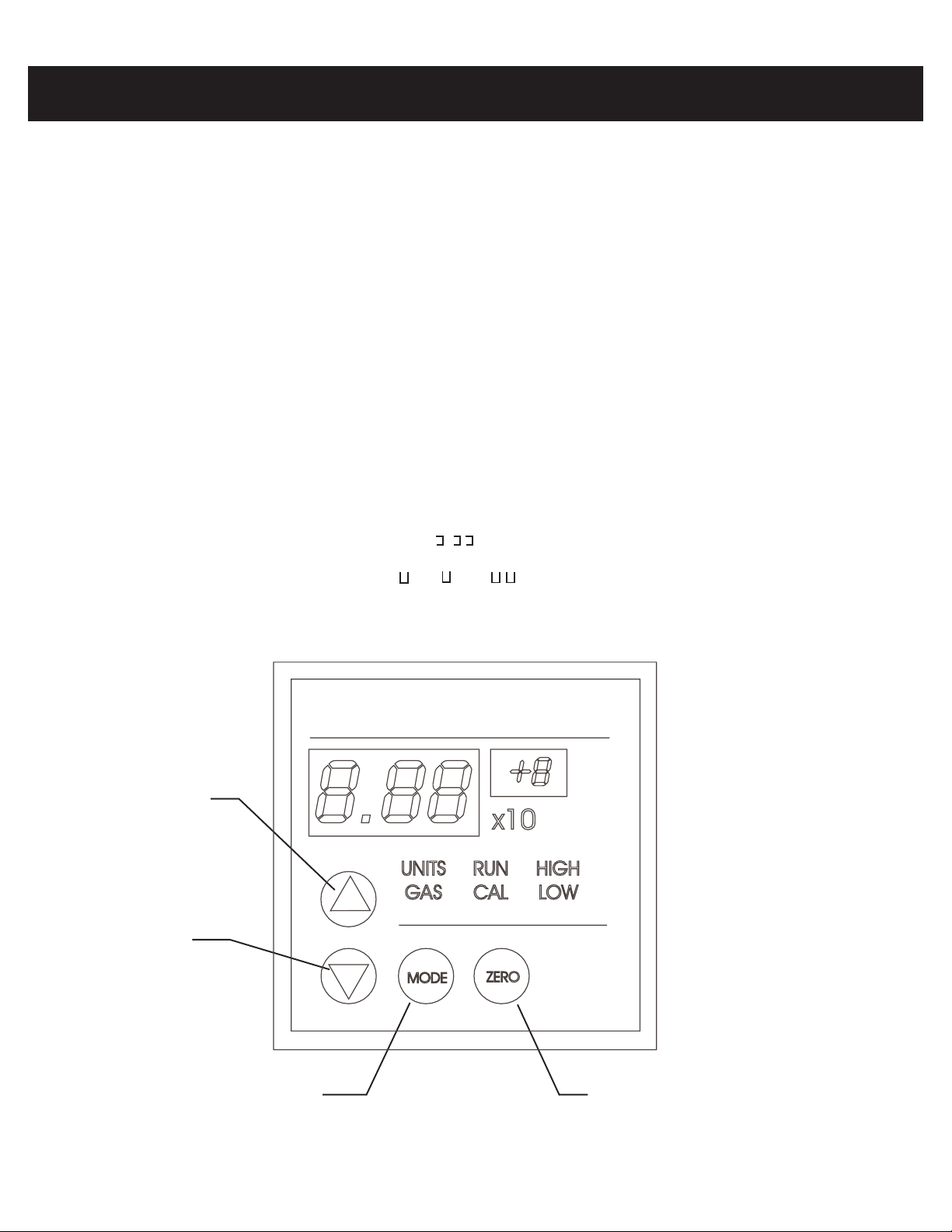
The front panel of the control unit is shown in Figure 3.1. The four circular blue buttons are
used for the selection of display readout and the input of data. The green data field displays the
data as determined by mode selection. The MODE switch toggles the control unit in a clockwise
fashion among the six modes of operation:
RR
UNUN
R
UN Normal operation, pressure is displayed in scientific notation. The analog to digital
RR
UNUN
converter speed can be adjusted and the factory calibration can also be restored in
this mode. See Section 3.2 for further information.
HIGHHIGH
HIGH High set point is displayed in scientific notation, above this pressure the HIGH
HIGHHIGH
TTL output will be +5V.
LOLO
WW
LO
W Low set point is displayed in scientific notation, below this pressure the LO W TTL
LOLO
WW
output will be +5V.
CALCAL
CAL Pressure is displayed and can be adjusted.
CALCAL
GASGAS
GAS Gas number is displayed and selection may be changed.
GASGAS
UNITSUNITS
UNITS Units used to display pressure are selected.
UNITSUNITS
SECTION 3
Front Panel Operation
In the RUN, HIGH, and LOW modes, it is possible to see the display indicate that the data is out
of range. Overrange is indicated by . x10- . Underrange is indicated by 0.0 x10-. A measured pressure below 1x10
sensor(s), it is possible to see “ .“, “. “ or “ . “. See trouble shooting section (section 8) for
more detail.
UP SWITCH
DOWN
SWITCH
-4
Torr is indicated by 0.0 x10+. In the case of an unconnected or faulty
HASTINGS INSTRUMENTS
DUAL SENSOR V ACUUM GAUGE
MODEL 2002
mbar
Torr
Pa
Model 2002
Control Unit
Front Panel
MODE SWITCH ZERO SWITCH
Model 2002 Control Unit Front Panel
Figure 3.1
Model 2002 page 9
Page 10

All six modes of the Model 2002 have features which can be accessed and modified after bypassing
the front panel interlock. The interlock is in place to prevent the accidental corruption of the
instrument’s configuration and calibration. The interlock is bypassed using the following steps:
1. Place the instrument in one of the six modes.
2. Simultaneously press the up and down switches.
The mode light will now flash indicating that the interlock has been bypassed.
Scientific NotaScientific Nota
Scientific Nota
Scientific NotaScientific Nota
The Model 2002 measures pressure that spans more than seven decades. In order to easily display
these readings, Hastings Instruments has employed scientific notation. In scientific notation, the
mantissa (the fixed point part) is multiplied by some power of 10 (given by the exponent).
103 = 1000 10-1 = 0.1
2
10
101 = 10 10-3 = 0.001
100 = 1 10-4 = 0.0001
As an example: 7.60 x 10
"7.60 multiplied by 100" = 760 Torr which is one atmosphere of pressure.
3.2 RUN Mode
NorNor
mal Operamal Opera
Nor
mal Opera
NorNor
mal Operamal Opera
tiontion
tion
tiontion
Powers of 10
= 100 10-2 = 0.01
+2
Tor r
{
mantissa exponent
tiontion
tion
tiontion
The Model 2002 will automatically enter RUN mode upon start-up. This is the mode for normal
operation and the mode in which the instrument will typically spend most of its time. In the run
mode, the Model 2002 unit will continuously monitor the pressure and update the alarm conditions
at the speed of the A/D con verter and will update the display about four times per second.
A/D Speed A/D Speed
A/D Speed
A/D Speed A/D Speed
The Model 2002 utilizes a 24 bit sigma-delta analog to digital converter. This type of converter
averages the input over time to reject interference. Longer averaging times result in more accurate
readings. Increasing the A/D speed will respond to sudden pressure changes faster.
While in the RUN mode, the user can adjust the A/D speed of operation. At start-up, the instrument
will be operating with an A/D frequency of about 60 Hz. The speed can be adjusted one step faster
or slower. Each step will increase or decrease the A/D frequency by a factor of two.
To adjust the A/D speed, press the MODE switch until the RUN light is illuminated. Then simultaneously press the UP and DOWN switches. The RUN light will now flash indicating tha t the
interlock has been bypassed and the A/D speed can be adjusted. Push the UP switch to speed up
the A/D conv erter one step and decrease the response time . This will result in a faster triggering of
alarms or relays if a sudden catastrophic failure occurs. Pressing the switch after the limit is reached
has no effect.
Pushing the down switch will slow down the A/D converter and increase its accuracy. This will
improve the ability to resolve low pressure readings. If a certain speed is desired, press the UP or
DO WN switch three times and then press the other switch to select the other speed.
On older units. There will be no indication of the operating speed other than the least significant
digits of the display will tend to run at higher speeds. On units with software version 1.60 and
AdjustAdjust
Adjust
AdjustAdjust
page 10 Model 2002
Page 11

above, press the ZERO switch to display the decimation ratio (filtering). The larger the ratio, the
longer the response time.
EEPREEPR
EEPR
EEPREEPR
There are interlocks built into the CAL mode to minimize the chance of accidental alteration of the
calibration coefficients, but if calibration alteration does occur, the EEPROM calibration data can be
restored in the RUN mode by pressing the UP and DOWN switches simultaneously (RUN light will
flash), then press the “ZERO” switch, UP and DOWN switches (all three) simultaneously.
This will not correct the calibration if the tube has become contaminated or damaged. This reset will
not affect the gas selection, units or setpoints.
Also see units mode for default calibration restoration.
OM CalibraOM Calibra
OM Calibra
OM CalibraOM Calibra
tion Restoration Restora
tion Restora
tion Restoration Restora
tiontion
tion
tiontion
3.3 HIGH and LOW Set Point Modes
The Model 2002 provides TTL outputs for process control. The I/O cable is attached via a 9-pin
sub-D connector to the rear panel of the control unit. The pinout is shown in Figure 4.2.
To view the high set point, place the Model 2002 in the HIGH mode by pressing the MODE switch
to illuminate the HIGH light and no other mode light. The display will show the set point selected.
During normal operation the alarm light will illuminate and the TTL output (pin # 3) will go high
(+5 V) if the pressure
Similarly, to view the low set point access LOW mode by pressing the mode switch until the LOW
light is lit and no other mode light is illuminated. During normal operation, the LOW light will
illuminate and the LOW alarm TTL output (pin # 4) will go high (+5 V) if the pressure becomes
less less
less than the set point.
less less
exceedsexceeds
exceeds the set point.
exceedsexceeds
The alarm lights cannot indicate an alarm condition while in the set point modes. Therefore, it is
advisable not to leave the instrument in these modes for extended periods.
To adjust a set point, press the mode switch until the set point is viewed. Then simultaneously press
the UP and DOWN switches. The active mode light will now flash indicating that the interlock has
been bypassed and the set point can be adjusted. The display shows the present set point.
Enter the new set point by using the UP and DOWN switches. Press and hold the UP switch to
increase the set point and the DOWN switch to decrease the setpoint. Allow a few seconds for the
circuitry to respond. If the button is held down for and extended period of time the adjustment rate
will start to increase. Release the button and press again to get finer control of the exact trigger
point.
At this point, the new set point is in temporary memory. If the instrument were unplugged now,
the Model 2002 would revert back to the original set point upon restarting. Return the 2002 to the
RUN mode to store the set point in permanent memory.
Once the interlock has been bypassed in the HIGH mode, it will stay active until the CAL mode is
entered. This will allow the user to set both setpoints without repeating the interlock bypass.
3.4 CAL Mode
Optimal performance of the Model 2002 is achieved by performing in situ adjustments to the
calibration coefficient in the CAL mode. There are three calibration coefficients. These are the zero
coefficient, the midrange coefficient and the atmosphere coefficient. Once a tube has been fully
calibrated the midrange coefficient should never need further adjustment, but it may be helpful to
adjust the zero coefficient or the atmosphere coefficient under certain situations. Even though the
operator inputs may be identical for adjustment of all three coefficients, microprocessor will detect
Model 2002 page 11
Page 12
Maintainance and Repair 4-3
the power level of the tube and adjust the proper coefficient for pressure level of the adjustment.
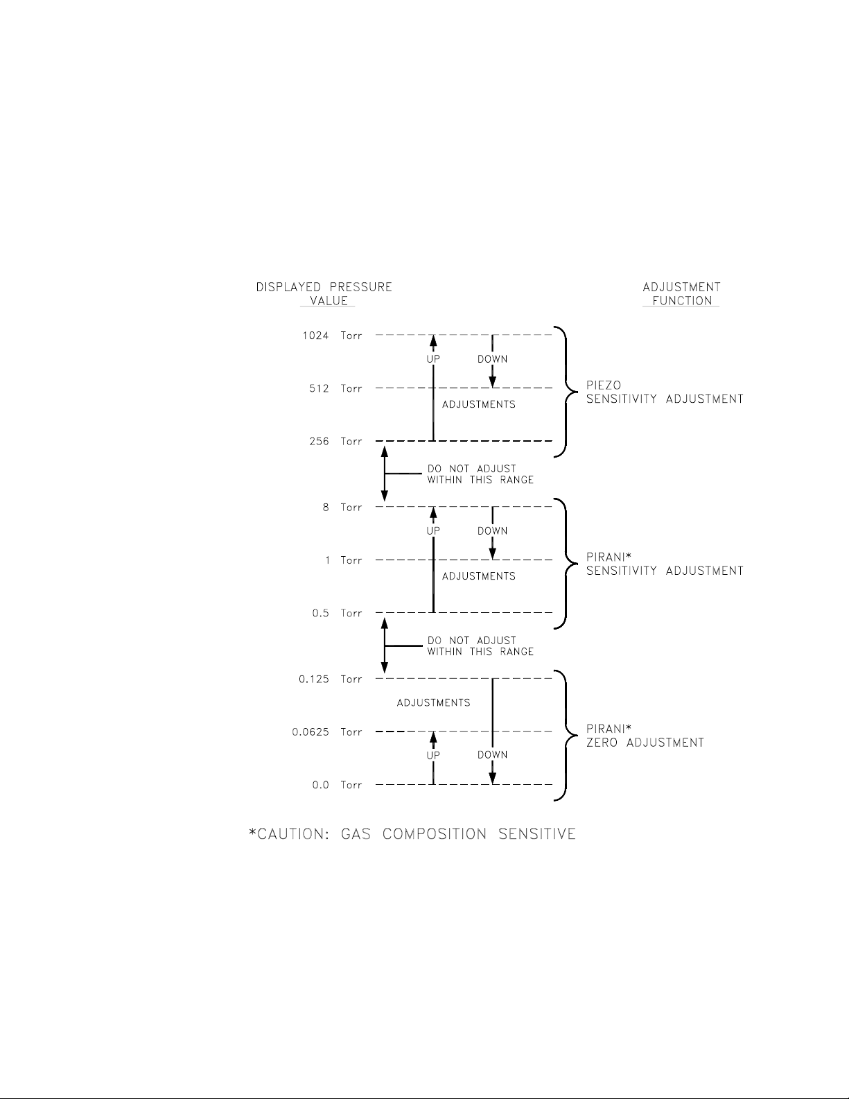
The CAL MODE presupposes that the operator is applying a known pressure of the correct gas
composition (see GAS MODE). The factory calibration points are 800 Torr, 7 Torr, and <1e-6
Torr. The users calibration points are not required to be exactly those values, but should be
somewhat close, and must be within the ranges shown in the following figure. The HPM-2002
detects the voltage signal within the sensor tube, which is converted and displayed as a pressure
reading. The resulting pressure reading determines which of the three coefficients will be adjusted.
page 12 Model 2002
To adjust a calibration coefficient press the MODE switch until the CAL light is illuminated.
Then simultaneously press the UP and DOWN switch. The CAL light will now flash indicating
that the interlock has been bypassed and the calibration can be adjusted. Press and hold the UP
switch to increase the displayed v alue or the DOWN switch to decrease the displayed value. If
the switch is held down for an extended period of time the adjustment rate will start to increase.
Release the switch and then press and hold again to regain finer control of the displayed number.
An important point to be noted is the fact that after the adjustment, the new calibration coefficient is only in temporary memory. If the instrument were unplugged at this point, it would rev ert
Page 13

back to the original displayed value upon restarting. Place the Model 2002 back in the RUN
mode to store all of the current calibration coefficients in permanent memory.
To perform a full calibration on the Model 2002 system, first use the Zero Coefficient Adjustment Procedure. Followed by the Midrange Coefficient Adjustment Procedure, and finally
perform the Atmosphere Coefficient Adjustment Procedure.
Zero Coefficient Zero Coefficient
Zero Coefficient
Zero Coefficient Zero Coefficient
The zero coefficient corrects for the constant power level which is present ov er the entire pressure
range. Typically, this adjustment corrects for low pressure errors. The instrument will need to be
re-zeroed often if measurements are being made in the 10-4 Torr range, especially if the ambient
temperature changes. The transducer may have a temperature coefficient of up to 2x10⁻⁴ Tor r/oC.
The instrument remote zero input will allow an external gauge such as an ion gauge to automatically re-zero the Model 2002 whenever the pressure drops below the desired pressure level (if it
has a TTL output).
NOTE: Do not attempt to zero the Model 2002 in pressures abov e 10-2 Torr; the microprocessor will not accept a zero abov e this pressure.
To manually adjust the zero use the following procedure:
1. If possible, evacuate the vacuum system into the low 10-6 T orr (1.33x10⁻⁶ mbar) range or as
low as possible below 10
2. Allow the sensor to operate in this condition for a minimum of 15 minutes.
3. Place the instrument in the CAL mode, then simultaneously press the UP and DOWN
switches to bypass the interlock. The CAL light will start to flash indicating
that the calibration mode has been activated.
4. Press the ZERO switch once if below 6x10⁻⁵ Torr otherwise use the UP and DOWN switch
to adjust the display of the Model 2002 to match the pressure indicated by
the reference. If using the UP and DOWN switch to adjust the display , wait 20
seconds between presses at very low pressure to allow the adjustment to take
affect the data to settle.
AdjustmentAdjustment
Adjustment
AdjustmentAdjustment
-4
Torr.
5. The unit is now fully zeroed. Place the Model 2002 back in the RUN mode to store the zero
in permanent memory.
Midrange Coefficient Midrange Coefficient
Midrange Coefficient
Midrange Coefficient Midrange Coefficient
The midrange coefficient corrects for errors in the slope of the power curve of the thin film
Pirani. Typically, this is due to the geometry of a particular sensor and will only need to be
performed once in the lifetime of the sensor. This adjustment might be needed if a full calibration
is being performed in a gas other than nitrogen.
before making this adjustmentbefore making this adjustment
before making this adjustment.
before making this adjustmentbefore making this adjustment
To adjust the midrange coefficient use the following procedure:
1. Evacuate the vacuum chamber and refill with the desired gas to a pressure of 7 Torr, as
indicated by a reference vacuum gauge.
2. Press the MODE switch repeatedly until the CAL mode is illuminated.
3. Simultaneously, press both the UP and DOWN switches. The CAL light will start to flash,
signalling that the calibration can now be conducted.
4. Press, hold and release the UP and DOWN switches as necessary to adjust the display to
match the pressure indicated by the reference. Note: It may be necessary to hold the
desired switch down for a few seconds before any movement is seen.
AdjustmentAdjustment
Adjustment
AdjustmentAdjustment
The zero adjustment will need to be perforThe zero adjustment will need to be perfor
The zero adjustment will need to be perfor
The zero adjustment will need to be perforThe zero adjustment will need to be perfor
medmed
med
medmed
Model 2002 page 13
Page 14

5. Press and release the MODE switch as necessary to return the 2002 to the RUN mode and
store the coefficients to permanent memory.
Atmosphere Coefficient Atmosphere Coefficient
Atmosphere Coefficient
Atmosphere Coefficient Atmosphere Coefficient
If a reference high pressure gauge is not available, the ambient barometric pressure acquired from
the weather channel or other weather service can be used to adjust the proper reading.
To adjust the atmosphere coefficient, use the following procedure:
1. Press the MODE switch a sufficient number of times to enter the CAL mode.
2. Simultaneously, press both the UP and DOWN switches to bypass the interlock. The CAL
light will start to flash, signaling that the calibration can now be conducted.
3. Press, hold and release either of the UP and DOWN switches as necessary to adjust the
display to match the pressure indicated by the reference. Note: It may be necessary to hold the desired switch down for a few seconds before any movement is
seen.
4. Press and release the MODE switch as necessary to return the Model 2002 to the RUN
mode and store the coefficients to permanent memory.
3.5 GAS Mode
The Model 2002 can provide true pressure measurements in many gas environments. At pressure
levels above 32 Torr where the direct force piezoresistive sensor is operative, the instrument is gas
composition insensitive and measures the true pressure regardless of gas composition. The Pirani
is gas composition sensitive so below 32 Torr, the actual composition must be known and the
Pirani calibrated in that gas. When the vacuum system’s gas composition is dominated by a single
gas species (for example, during system venting with an inert gas), the user can enter a gas
selection into the Model 2002. To view the gas selection, place the instrument in the GAS mode
AdjustmentAdjustment
Adjustment
AdjustmentAdjustment
page 14 Model 2002
TABLE 1
Gas Mode
Displayed Number
0.0............................... nitrogen
0.1................................... argon
0.2................................. helium
0.3..........................water vapor
0.4.................................custom
and reference Table 1. The Model 2002 is factory set to display N2 pressure readings. To select a
different gas, refer to Table 1 to find the number code of the gas to be entered. Press the UP and
DOWN switches simultaneously, the GAS light will now flash. Use the UP and DOWN switches
to individually select the desired code. Return the Model 2002 to the RUN mode.
Gas
Page 15

Note: Factory calibration is performed using nitrogen only. Displayed pressure measurements using other gases are based on established g as thermal conductivity data.
3.6 UNITS Mode
The Model 2002 can display the measured pressure in different pressure units, Torr, mbar or
Pascal. To switch between these units press the MODE switch until the UNITS field is lit. Press
the UP and DOWN switches simultaneously. The UNITS light will now flash. Use the UP and
DO WN switches individually to select the desired unit.
The units mode is also used to display the RS-485 address, (see section 6.3).
A commonly used unit is mTorr which is also known as the micron (short for micron of Hg).
One Torr is equal to 1000 mTorr. The table below illustrates how to interpret the display in
mTorr.
Table 2 gives conversion factors for the most often used pressure units.
mTorr Conversions
1 mTorr = 1.00 x 10⁻³ Tor r
10 mTorr = 1.00 x 10⁻² Tor r
100 mT orr = 1.00 x 10
-1
Tor r
TABLE 2
Torr
Torr (mm Hg)
mTorr (micron Hg)
atm (athmosphere)
mbar (millibar)
Pa
1 1.32x10
-3
10
760
0.75
7.5x10
-3
psi (lb/in ) 51.72
Default CalibraDefault Calibra
Default Calibra
Default CalibraDefault Calibra
The UNITS mode is also used to load default calibration data in rare cases where the transducer
EEPROM has become corrupted. The default calibration data should be considered an approximate calibration because the values entered in the controller’s software are based on averaged data
collected over a large number of transducers. While this type of calibration download is not a true
calibration, it does allow the user to return the unit to a reasonable status from which a full
calibration can be easily performed.
tion Restoration Restora
tion Restora
tion Restoration Restora
tiontion
tion
tiontion
atm
-3
1.3332 133 .32
1.32x10
9.869x10
9.869x10
6.805x10 68.953
-6
0.00133
1
1013.23
-4 -2
-6
-2
1
0.01
.13332
1.013x10
100
1
6895.3
psiPambar
1.934x10
1.934x10
14.7
1.45x10
1.45x10
1
-2
-5
-4
Model 2002 page 15
Page 16

This page was intentionally left blank
page 16 Model 2002
Page 17

A schematic of the rear panel of the Model 2002 control unit is shown in Figure 4.2 ( Rear Panel Figure).
The transducer is connected to the control unit via an female 9-pin “D” connector on the rear panel. An
I/O cable can be connected via a male 9-pin “D” connector on the rear panel. The I/O cable provides an
analog output signal, a remote zero input capability, high and low alarm TTL outputs, and a + 5 VDC
Power Supply Output. The I/O cable also provides an analog ground and a digital common.
4.1 Remote Zero Input
The Model 2002 can be zeroed remotely via the I/O cable using the remote zero input line. Upon setting
this line to TTL low level, the instrument will set its current pressure reading to zero. A common application of this feature is to utilize a process control output from a high vacuum gauge (for example an ion
gauge controller) to automatically zero the Model 2002 whenever the pressure is below the low 10-5 Torr
range. A Digital Common is provided on pin # 5 which can be used with relay contacts or switch
contacts to remotely zero the instrument.
4.2 Analog Output
The Model 2002 provides an analog voltage output signal (0.5 VDC linear per decade) for process
control and for pressure monitoring. A plot of the analog output signal as a function of pressure is
shown in Figure 4.1 . Note that the output voltage is directly proportional to the pressure over each
complete decade (see detailed region in Figure 4.1) and that each decade has a different linear slope.
SECTION 4
Rear Panel Description
Above an indicated pressure of 103 Torr, the analog output signal will be +5 VDC. Below the minimal
displayable pressure of 1 x 10⁻⁴ Torr, the analog output will be 1.0 VDC.
(EXP + 6) (MANT - 1)
V =
The analog output voltage is given by the following equation:
Where EXP is equal to the exponent of the displayed pressure.
218
+
EXP = -2
MANT = 1.53
(1.53 - 1)
+
18
example: p = 1.53 x 10
(-2 + 6)
V =
-2
2
2 + 0.0294
=
2.0294 VDC
=
EXP = +2
MANT = 9.87
(+2 + 6)
V =
4 + 0.4928
=
4.4928 VDC
=
2
(9.87 - 1)
+
18
Model 2002 page 17
Page 18

If the analog output voltage is being used in a data aquisition system, the following formulas can
be used to calculate pressure.
EXP = INT (2*V)-6
MANT = 1 + 18 *V-9*(EXP + 9)
Pres su re (T o rr ) = Mant x 1 0
Therefore,
Note that the INT function simply returns to the first digit in a number.
examples:
INT (2.56) = 2
INT (9.87) = 9
Voltage to pressure conversion example:
Given V = 2.35 Volt
First calculate the exponent;
EXP = INT (2*2.35) - 6
= INT (4.7 - 6
EXP
Next calculate the mantissa;
MANT = 1 + 18 * V - 9 (EXP +6)
Finally the pressure is given by;
Pressure (torr) = MANT x 10
= INT 4-6
= - 2
= 1 + 18 * (2.35) - 9 * (2+6)
= 1 + 42.3 - 36
= 7.3
EXPEXP
EXP
EXPEXP
-2 -2
-2
= 7.3 x 10
-2 -2
Torr
page 18 Model 2002
Page 19

2.5
2.4
2.3
2.2
4.5
4.0
3.5
3.0
2.5
2.0
VDC
1.5
1.0
0.5
0.0
1.0E-5 1.0E-4 1.0E-3 1.0E-2 1.0E-1 1.0E+0 1.0E+1 1.0E+2 1.0E+3
VDC
2.1
2.0
12345678910
X 10-2 Torr
0.5 VDC Linear per Decade
Pressure (Torr)
4.3 4.3
TTL OutputsTTL Outputs
4.3
TTL Outputs
4.3 4.3
TTL OutputsTTL Outputs
MODEL 2002 MODEL 2002
MODEL 2002
MODEL 2002 MODEL 2002
Analog OutputAnalog Output
Analog Output
Analog OutputAnalog Output
Figure 4.1
VDC (volts) -vs- Pressure (Torr)
TTL outputs are provided for process control. High and Low set points are entered on the front panel
(see Section 3.4) and TTL signals are generated on the I/O cable in the following manner:
1) When the pressure as indicated by the Model 2002 is abov e the High set point, the High
signal line (pin #3) will be set to a TTL high level (+5 VDC). When the indicated pressure
is below the High set point, the High signal line (pin#3) will be set to a TTL low level (+0 VDC).
2) When the pressure as indicated by the Model 2002 is below the Low set point, the Low signal
line (pin #4) will be set to a TTL high level (+5 VDC). When the indicated pressure is above
the Low set point, the Low signal line (pin #4) will be set to a TTL low level (+0 VDC).
These TTL signals are used for a variety of applications. With these signals, the user has the capability
to turn off/on various equipment such as valves, flo w controllers, pumps, heaters, and safety equipment.
Model 2002 page 19
Page 20

4.4 Power Entry Module
The AC power for the Model 2002 enters the instrument through a power entry module that
contains a fuse, on/off switch and an IEC 320 power inlet.
The fuse is rated for 250 V, 1/4 A. It can be accessed by unplugging the AC cord and prying the
fuse compartment open with the tab and slot in the power inlet chamber. There is a spare fuse in
the compartment within the fuse holder.
LOW SETPOINT OPTION BOARD HIGH SETPOINT
RELAY CONNECTOR (MALE) RELAY
Model 2002
Rear Panel Detail
TRANSDUCER CONN. STANDARD
(FEMALE) I/O CONNECTOR
Analog 0-10V OPTION
BOARD CONNECTOR
Pin# Connection
1 Analog Out 1 (1024 Torr) High
2 Analog Out 1 (1024 Torr) Shield
3 Analog Out 1 (1024 Torr) Low
4
5
6
7 Analog Out 2 (1000 mTorr) Low
8 Analog Out 2 (1000 mTorr) High
9 Analog Out 2 (1000 mTorr) Shield
4-20mA OPTION
BOARD CONNECTOR
Pin# Connection
1 I-Loop Out (+) 1024 Torr
3 I-Loop In (-) 1024 Torr
8 I-Loop Out (+) 1000 mTorr
7 I-Loop In (-) 1000 mTorr
Figure 4.2
SENSOR CONNECTOR
Pin# Connection
1 Sensor
2 Bridge (sense)
3 Bridge-Power
4 Reference
5 Common
6 Common (sense)
7 N/C
8 N/C
I/O CONNECTOR
Pin# Connection
1 Analog Output
2 Analog Common
3 High Setpoint
4 Low Setpoint
5 Digital Common
6 Remote Zero
7 +5V
page 20 Model 2002
Page 21

The Model 2002 transducer is comprised of two very different sensors which provide a span of
measurement extending from 1000 Torr down to less than 1x10⁻⁴ Torr. The piezoresistive device is
a direct force sensor which provides pressure indication from 1000 Torr down to less than 1 Torr.
The thin film Pirani device is a thermal conductivity sensor that provides pressure indication
from 100 Torr down to less than 1x10
convenient for smooth transition either descending or ascending in pressure. Both sensors are
small micromachined die that are bonded to a Au coated Al2O3 preform (stress isolation) which in
turn is bonded to a TO-8 header. The header is resistance welded into a 316 stainless steel
envelope as shown in Figure 5.1.
5.1 Piezoresistive Sensor
Cable connector
SECTION 5
Theory of Operation
-4
Torr. The two decade overlap in measurement range is
Electronics board
(contains EEPROM)
Top cap
TO-8
HEADER
Piezoresistive
sensor
Tube shell
Dual Sensor Embodiment
Preform
Pirani sensor
Figure 5.1
Model 2002 page 21
Page 22

V
T
Figure 5.2 shows a typical schematic of a B implanted Wheatstone bridge network in a Si diaphragm inverted box type geometry. The inside of the box is evacuated during anodic bonding to
a Pyrex substrate. The membrane has maximum deflection at atmosphere (or higher pressure)
and the membrane resistances change value as the differential pressure is decreased during
pumpdown. The resulting differential output is
VdS
dT
1
)
Vo = SPV+V
where
S is the sensitivity
P is the pressure
V is the applied bridge voltage
1
is the no load output voltage
V
Since the sensitivity changes so dramatically with temperature, some correction is required for
compensation. The change in output voltage
To insure temperature invariance,
dV
dT
0
SdV
P
(
d
dV
dV
0
dT
which requires for any change in sensitivity to be countered by an equal but opposite change in
applied voltage. The temperature compensation is a network of tempera ture dependent resistive
components and fixed temperature compensation current source compensation, TCR = -TCS.
Sensitivity of the sensor is proportional to the sensor factor (K), the strain gauge positioning of
the diaphragm (φ) and the diaphragm geometry (θ) thus S
the resistive film and piezo membrane have been established, the sensor factor is dependent on
the crystal orientation of the membrane material, the doping level and diffusion parameters and
the strain gauge geometry. The sensor factor is essentially the change in resistance for a change in
strain or,
Boron ion implanted doped Si matrix resistance elements are employed as shown in Figure 5.2.
0
therefore
1
dT
dS
1
dT
S
∝Kφθ. Once the defining geometry of
R
K
R
L
L
page 22 Model 2002
The die is electrostatically bonded on to a Pyrex substrate in a good vacuum so that the die cavity
is evacuated, this provides maximum deflection at atmospheric pressure. When the sensor is
exposed to vacuum the deflection becomes less and less as the die cavity pressure and the
vacuum system pressure equalizes. Eventually the strain in the membrane due to ∆P becomes
zero and only the residual strain in the lattice remains. The bridge resistive elements are oriented
to give maximum change in bridge resistance which in turn gives maximum voltage out for a
given strain.
Page 23

Diaphragm
Backing surface or
restrainer
Pressure
Diffused bridge resistors
View A-A
Diffused bridge resistors
E
e
S
1
e
2
Ground
A-A
Ground
Figure 5.2
Model 2002 page 23
Page 24

5.2 Pirani Sensor
Figure 5.3a shows a thin film Pt resistive element on a one micron thick Si3N4 continuous membrane surrounded by a thin film Pt reference resistor on a Si substrate. The membrane is heated
to a constant 80C above ambient temperature that is monitored by the substrate resistor. The
membrane resistor is approximately 60 Ω and a constant substrate to membrane resistance ratio
is maintained at 3.86. Figure 5.3b shows the Pirani die in cross section. A parallel Si lid is
eutectically bonded to the Au pads and sits 5 microns above the membrane. As shown, this
dimension gives a Knudsen number of greater than 0.01 up to atmospheric pressure, which
insures a molecular flow component. At 10 Torr the region above the membrane is totally in the
molecular flow regime and thus provides a relatively linear output verses pressure ov erlapping the
linear output versus pressure of the piezo.
The measurement technique is to produce an output signal that is proportional to the power
supplied to the heated resistor by using the product of the current and voltage. This rejects errors
introduced by resistance changes since the sensor resistance is no longer part of the power
equation.
A signal proportional to the power is obtained by multiplying the voltage across the heated sensor
and the voltage impressed by the direct current across a constant series resistance. The power
supplied to the sensor resistor must equal the heat dissipated (E
routes from the heated sensor are thermal conduction through the silicon nitride membrane to the
silicon substrate (Es) radiation losses (Er) and thermal conduction through the gas to the silicon
substrate (Eg); thus, as shown in Figure 5.3c,
EE
= E = E
E
= E
EE
= E = E
tt
t
tt
+ E + E
+ E
+ E + E
ss
s
ss
+ E + E
+ E
+ E + E
rr
r
rr
). The three main heat loss
t
gg
g
gg
The first term, Es, is dependent on the thermal conductivity of the silicon nitride (K), the temperature difference (∆T) between the heater and silicon substrate and geometric factors (AM &
L). ES is given by
EE
= (K = (K
E
= (K
EE
= (K = (K
ss
s
ss
∆∆
∆
∆∆
T T
T
T T
AA
A
AA
mm
m
mm
)/L)/L
)/L
)/L)/L
Am is the membrane cross sectional area through which the heat transfer occurs. This is, approximately, the outer circumference of the membrane multiplied by the membrane thickness. L is the
distance from the edge of (Rs) the heated sensor resistor to the silicon substrate.
For any particular sensor, all of the factors, except ∆T, are constants dependent on its construction. The ∆T is held constant by the control circuit. The thermal loss through the silicon nitride
will be a constant value independent of the thermal conductivity and pressure of the gas.
Radiation is another source of thermal losses. It can be determined from
44
44
4
4
44
EE
= =
σεσε
=
= =
rr
r
rr
σε
σεσε
(T(T
(T
(T(T
E
EE
44
-T-T
)A)A
-T
)A
-T-T
)A)A
hh
aa
h
hh
ss
a
s
aa
ss
where
σ = Stefan-Boltzmann radiation constant
ε = thermal emissivity of the silicon nitride membrane
AS= surface area of the heated portion of the membrane
Th= temperature of R
s
Ta= ambient temperature
page 24 Model 2002
Page 25

Temperature compensation
resistor (Pt)
Silicon nitride membrane
Heated sensor
resistor (Pt)
Silicon substrate
Silicon lid
x
Membrane
Silicon lid
Figure 5.3a
Au
Silicon base
TO-8 header
Figure 5.3b
Es
Er
Membrane
Eg
Er
Silicon base
Es
Figure 5.3c
Model 2002 page 25
Page 26

This radiation loss is also independent of the thermal conductivity of the gas. It is somewhat
dependent upon the absolute temperature of R
and the ambient temperature, but since ∆T is
s
kept to less than 20°C, this loss is only approximately 10% of Es. If ambient changes are small
compared to the absolute values of the temperature this loss can approximated as a constant with
temperature.
Since the first two losses are essentially constant at high vacuum for a given sensor, we can
measure these losses and subtract them from the input power which leaves only the ra te of heat
transmission through the gas (E
In the viscous flow regime, the E
).
g
loss is directly dependent on the thermal conductivity of the gas
g
(Kg), the surface area of the membrane, the differential temperature and is inversely proportional
to distance between the membrane and the lid. It can be written as
EE
E
EE
gg
g
gg
= (K = (K
= (K
= (K = (K
∆∆
T T
AA
)/)/
∆∆
A
AA
xx
)/
∆
x
)/)/
∆∆
xx
ss
s
ss
∆
T
∆∆
T T
gg
g
gg
The thermal conductivity of the gas is essentially constant when in viscous flow where the
Knudsen number (Kn) is less than 0.01. In the viscous flow regime there is no change in sensor
output with pressure since all of the losses are constants with pressure.
In the molecular flow regime where (Kn > 1) the thermal conductivity of the gas becomes
directly proportional to the gas pressure as shown below. We can expect then that Eg will be
constant at high pressures and directly proportional to the pressure at low pressures. The energy
loss Eg, changes between these two controlling equations as the system passes through the
transition region (0.01 < Kn < 1).
1/21/2
1/2
EE
= =
aa
LL
a
L
aa
LL
rr
r
rr
(273/T(273/T
(273/T
(273/T(273/T
tt
t
tt
E
=
EE
= =
gg
g
gg
1/21/2
))
(T(T
-T-T
)A)A
)
(T
(T(T
hh
h
hh
-T
-T-T
))
hh
h
hh
aa
a
aa
)A
)A)A
PP
P
PP
gg
g
gg
Where
ar= accomodation coefficient
Lt= free molecule thermal conductivity
Th= temperature of heated membrane
Ta= ambient temperature
P = pressure
Ag= surface area of the heated portion of the membrane
For nitrogen at a pressure of 760 Torr and a temperature of 20°C the mean free path (λ) is less
than 1 x 10⁻⁷ meters and is inversely proportional to pressure. Since the thermal transfer distance
(∆x) is a few micrometers, this sensor will remain in the molecular flow regime at a much higher
pressure (10 Torr) than is typical for a thermal vacuum gauge. This extends the linear response
part of the output curve up into the 1 Torr range. The nonlinear transition region will extend up
to 1000 Torr.
5.3 Dual Sensor Operation
The microprocessor in the control unit continuously monitors the outputs of both the piezoresistive
sensor and the Pirani sensor. Figure 5.4 shows representa tions of the sensors output ov er the
pressure range from 10
sensor at high pressures (>32 Torr) and uses the output of the Pirani sensor at low pressures (<8
Torr). In the crossover region, a software a v eraging algorithm ensures a smooth transition between
the two sensors.
-5
Torr to 10
+3
Torr. The microprocessor uses the output of the piezoresistive
page 26 Model 2002
Page 27

1.0E+03
1.0E+02
1.0E+01
1.0E+00
1.0E-01
1.0E-02
Model 2002
Dual Sensor Vacuum Ga uge
1.0E-03
Pirani
Piezo
Zeroed Sensor Output (Arbitrary Units)
1.0E-04
1.0E-05
1.0E-05 1.0E-04 1.0E-03 1.0E-02 1.0E-01 1.0E+00 1.0E+01 1.0E+02 1.0E+03
Pre ssu re (Torr)
Figure 5.4
Model 2002 page 27
Page 28

This page was intentionally left blank
page 28 Model 2002
Page 29

Both RS-232 and RS-485 communication interface boards are available as an option for the
Model 2002. The communication option boards allow data to be output to a host computer with
the appropiate interface. Connection to the RS-232 or RS-485 communication interface boards
are via a 9 pin D-subminiature female connector.
6.1 RS-232-E Interface Specifications
Format ................................. EIA standard RS-232-E, full-duplex, no handshaking, asynchronous
Data Rate......................................................................................................................... 9600 baud
Character Length ...................................................................................................... Eight data bits
Parity ................................................................................................................................. No parity
Stop bits.........................................................................................................................One stop bit
A common application of the RS232 version of the HPM-2002, is to connect the pressure gauge
directly to the serial port of a PC. This is done by first wiring a communication cable in the
SECTION 6
Communications Option Board
Figure 6.1
manner shown below.
PIN MNEMONIC SIGNAL DESCRIPTION
2 TX Transmit Data Transmits data within RS-232-E voltage levels
3 RX Receive Data Accepts data within RS-232-E voltage levels.
5 SG Signal Ground Establishes the common ground reference
potential for all interchange circuits
when communicating via RS232-E.
4 CTS Clear to send Host computer ready to accept data. (Reserved
for future use, not implemented by present
software.
8 RDY Ready Ready to receive data (always high, not
implemented by present software.
Model 2002 page 29
Page 30

6.2.1 Interface Connector Pin Assignments for RS-485
(full duplex-4 wire)(jumper position 2-3).
PIN MNEMONIC SIGNAL DESCRIPTION
2 TX+ Transmit + Differential data
signal levels to
8 TX - Transmit - the RS-485 bus
3 RX+ Receive + Differential data
4 RX- Receive - the RS-485 bus
6.2.2 For RS-485 (Half Duplex - 2 wire)
(jumper position 1-2).
}
signal levels from
}
PIN MNEMONIC SIGNAL DESCRIPTION
2 TX+/RX+ Transmit +/Receive + Differential data
signal levels to and from
8 TX-/RX- Transmit -/Receive - the RS-485 bus
6.2 Interface Connector Pin Assignments for RS-232
Note: an alternate method of connecting to a 2 wire bus is to leave the interface configured for
full duplex and externally connect pins 2 and 3 to the(+) bus and pins 4 and 8 to the (-) bus.
6.3 Operation of the Serial Interface
Communication with the serial interface of the Model 2002 is via an ASCII data string. In the RS-232
mode the command message consist only of a command string and the terminator. The attention
character and address string are not required, but if they are used they MUST be valid. If all components of the ASCII data string are valid the command will be accepted and executed. The RS-232
mode is sometimes referred to as point-to-point mode since only one device may be connected to the
controller at any given time.
}
page 30 Model 2002
A message to the Model 2002 in the RS-485 mode consist of an attention character followed by
the address string , the command string, and the terminator. If all components of the ASCII data
string are valid the command will be accepted and executed. The RS-485 mode is also referred to
as multipoint mode since up to 31 devices may be connected to the same controller in a network
scheme.
The RS-485 address may be display on the model 2002 front panel (with software verson 1.60 or
higher). Press the MODE switch until the units field is lit, press both the UP nad DOWN
switches simultaneously. The units light will now flash. Press the ZERO switch to display the
Page 31

RS-485 address
the address. Use the MODE s witch to exit this function and save the new address into EEPROM
memory.
(the address is displa(the address is displa
(the address is displa
(the address is displa(the address is displa
yy
ed in it’ed in it’
y
ed in it’
yy
ed in it’ed in it’
s decimal fors decimal for
s decimal for
s decimal fors decimal for
m)m)
m). Use the UP or DOWN switch to modify
m)m)
COMMAND SYNTCOMMAND SYNT
COMMAND SYNT
COMMAND SYNTCOMMAND SYNT
In the following examples of syntax codes, the special characters are explained:
The characters in square brackets [ ] represents a command string, either upper or lower case command
characters accepted. All characters must follow each other in the string with no spaces or other characters.
The characters within wavy brackets { } contain choices for the appropriate command.
The characters within the symbols < > are the common abbreviations for the one digit ASCII control
codes which they represent, (e.g. <CR> represents carriage return).
When entering more than one command in the same data string, they must be separated by a comma.
All command strings must be followed by the terminator character (carriage return <CR>, also known
as ENTER).
When a lower case character is present in an example it represents an option.
Character Description Valid Inputs:
a RS-485 Address (hexadecimal 0-9, A-F) 01 - FF
m Most Significant Digit Of Mantissa 1 - 9
d Decimal Digit 0 - 9
AXAX
AX
AXAX
e Exponent 0 - 5
u Unit Of Pressure T, M, or P
, Command Separator (comma) N/A
<CR> Command T erminator (carriage return) N/A
InterInter
rogaroga
Inter
InterInter
Command Description Format Sample Response
Transmit A v eraged Pressure P<CR> Pa: 1.23456e+0 Torr<CR>
Transmit Pirani Pressure R<CR> Pr: 1.98765e-3 Torr<CR>
Transmit Piezo Pressure Z<CR> Pz: 7.65432e+2 Torr<CR>
Transmit RS-485 Address A<CR> Multidrop Address: 01<CR>
Transmit Decimation Ratio D<CR> Decimation Ratio: 255<CR>
Transmit Selected Gas # G<CR> Gas#: 0<CR>
Transmit High Setpoint H<CR> Hi: 1.00000e+1 Torr<CR>
tion Commandstion Commands
roga
tion Commands
rogaroga
tion Commandstion Commands
Transmit Low Setpoint L<CR> Lo: 1.00000e-2 Torr<CR>
T ransmit Device Sta tus S<CR> 00044<CR>
Transmit T urnaround Delay T<CR> Comm Delay: 6<CR>
Model 2002 page 31
Page 32

Transmit Selected Units U<CR> Torr<CR>
Transmit Software Version# V<CR> Hastings Instruments - Model 2002
Version 1.60 - (07-02-2002)<CR>
PP
arameter Modificaarameter Modifica
P
arameter Modifica
PP
arameter Modificaarameter Modifica
Command Description Format Valid Range:
Modify High Setpoint H={m.dd}E{+e}<CR> 1.00000e-9 to 9.99999e+9
Modify Low Setpoint L={m.dd}E{-e}<CR> 1.00000e-9 to 9.99999e+9
Modify Selected Gas # G={d}<CR> 0 T o 4 (Decimal)
Modify Selected Units U={u}<CR> T, or M, {or P, if Available}
Modify Decimation Ratio D={dddd}<CR> 63 T o 7936 (Decimal)
Modify RS-485 Address *{aa}A={aa}<CR> 1 T o FF (Hexadecimal)
Modify T urnaround Delay *{aa}T={dd}<CR> 0 T o 255 (Decimal)
Notes:Notes:
Notes:
Notes:Notes:
tion Commandstion Commands
tion Commands
tion Commandstion Commands
The setpoints may also be entered as a decimal number, e.g. [H=760.99<CR>] will be same as
entering [H=7.6099E+2<CR>] .
When inputting setpoint data, it should be entered in the same Units of Pressure as the presently
selected Units of Measurement (i.e.Torr, mbar or Pascal). The data is only checked to be a valid
number with a one digit exponent before being accepted. There are no limit checks on the data,
the user is free to choose any value appropriate to his use of the instrument.
The Turnaround Delay and RS-485 address are unique to multipoint communications. In order
to prevent inadvertent modifications of these parameters, the multipoint attention character and
the Model 2002’s present address [*{aa}] MUST be used and are checked for validity before the
command is executed.
If the RS-485 address is unknown, the ‘UNIVERSAL ADDRESS’ [*00] may be used to set the
address to a known value, e.g. [*00A=35<CR>] will change the RS-485 address to 35.
Caution:Caution:
Caution: Since all units will respond to the ‘UNIVERSAL ADDRESS’, make sure that only
Caution:Caution:
the unit to be modified is connected to the RS-485 Bus. If more than one unit is connected, this
will result in all of the units being set to the same address.
The value entered for the T urnaround Delay is used to modify an internal timer which normally
runs at ~8 millisecond, e.g. [*{aa}T=10<CR>] will set the delay to ~80 milliseconds.
If the command syntax is not met or if the number is out or range, the HPM-2002 will respond
with the ASCII codes for <bell>?<CR>, and the command will be ignored.
page 32 Model 2002
CalibraCalibra
Calibra
CalibraCalibra
Command Description Format Valid Range:
tion tion
Adjustment CommandsAdjustment Commands
tion
Adjustment Commands
tion tion
Adjustment CommandsAdjustment Commands
Page 33

Set Full Scale Calibration CF={m.d}E{e}<CR> 5.12e+2 to 1.023e+3 Torr
6.83e+2 to 1.365e+3 mbar
6.83e+4 to 1.365e+5 Pascal
Set Midpoint Calibration CM={m.d}E{e}<CR> 4.00e+0 to 7.999e+0 Torr
5.34e+0 to 1.066e+1 mbar
5.34e+2 to 1.066e+3 Pascal
Set Lowpoint Calibration CL={m.d}E{e}<CR>
0 to 1.249e-1 Torr
0 to 1.666e-1 mbar
0 to 1.666e+1 Pascal
Notes:Notes:
Notes:
Notes:Notes:
The calibration adjustment data may also be entered as a decimal number, e.g.
[CF=760.99<CR>] will be same as entering [CF=7.6099E+2<CR>] .
When inputting calibration adjustment data, it must be within the valid range of the presently
selected Unit of Measurement (i.e. Torr, mbar or Pascal). The data is checked to be valid before
being accepted.
If the command syntax is not met, or if the number is out or range, the HPM-2002 will respond
with the ASCII codes for <bell>?<CR>, and the command will be ignored.
Reset / Restore CommandsReset / Restore Commands
Reset / Restore Commands
Reset / Restore CommandsReset / Restore Commands
Command Description Format Notes :
Escape <Esc> Reset Command Buffer (ignore prior
Input
Software Reset /R<CR> Reinitialize Software
Restore Factory Defaults /#<CR> Restore Calibration Register Default
Values
Set Zero /0 <CR> Store Present Pressure As Instrument
ZERO (if Piezo <32 Torr & Pirani <50
mTorr)
Force Zero /!<CR> Override Limit Checks And Store
Present
Pressure As Instrument ZERO
Model 2002 page 33
Page 34

Device Status
When requested to transmit its status the Model 2002 responds with a five digit number which is
explained in the following:
Serial Receiver Overflow = 4
Main Board EEPROM Error = 2
Probe EEPROM (any) Error = 1
Probe EEPROM Not Responding = 8
Probe EEPROM Read Error = 1
Probe EEPROM Checksum Error = 4
Probe EEPROM V erification Error = 2
Probe EEPROM Identification Error = 1
digdig
dig
digdig
it#:it#:
it#:
it#:it#:
1 1
1
1 1
○○○
2 2
2
2 2
○○○○○○○○○○○○
3 3
3
3 3
4 4
4
4 4
○○○○○○○○○○○○○○○○○○○○
5 5
5
5 5
○○○○○○○○○○○○○○○○○○○○○○○○○○○○○
○○○○○○○○○○○○○○○○○○○○○○○○○○○○○○○○○○○○○○○
Communications Syntax Error = 4
Piezo Sensor Bad (voltage out of range) = 2
Pirani Sensor Bad (voltage out of range) = 1
High Setpoint Alarm (pressure exceeds setpoint) = 4
Low Setpoint Alarm (pressure less than setpoint) = 2
Gas# Changed (not the same as when unit last calibrated) = 1
page 34 Model 2002
Page 35

The relay interface board is available as an option for the Model 2002. Additionally, relays may
be added to either the Digital option Board (RS-232 or RS-485) or to the Analog option Board
(0-10 Volts or 4-20mA). In either case the relays operate independently of the other options. The
relay board allows the TTL logic setpoints (High, Low) to directly control tw o SPDT relays.
Whenever the setpoint indicator light in the front panel is lit, the corresponding relay is energized.
The relay contacts are rated for a maximum switching current of 250VA (resistive load). Connection to the relay contacts is made via connector mounted through the rear panel of the Model
2002. Screw terminals, on the mating connector, are designed for wire from 28 AWG through 14
AWG.
7.1 Relay Board Specifications
Each relay board consists of 2 Form C (SPDT) relays with the contacts wired in parallel.
Max. s witching power --------------------------------------------------------------------- 120W, 250VA
Max. s witching voltage -------------------------------------------------------------- 220VDC, 250VAC
SECTION 7
Relay Interface Option Board
(2A @ 125VAC, 1A @ 250VAC)
Max. switching current ---------------------------------------------------------------------- 4A DC, AC
Max . carrying current----------------------------------------------------------------------- 6A DC, AC
UL/CSA rating --------------------------------------------------------------------------1.2A @ 125VAC
LOW SETPOINT
RELA Y CONNECTOR
Connector for Digital or Analog option,
or dummy connector if no option
is installed
1.2A @ 110VDC
4.0A @ 30VDC
HIGH SETPOINT
RELA Y CONNECT OR
3 2 1
COMMON
NC
NO
3 2 1
NC
NO
COMMON
Figure 7.1
Model 2002 page 35
Page 36

7.2 Relay Connector Pin Assignment
7.3 Operation
page 36 Model 2002
Page 37

SECTION 8
4-20 mA Interface Option Board
The Relay option board in the Model 2002 operates off of the setpoints defined by the user and
programed into the Model 2002 microprocessor. For more informa tion about configuring these
setpoints refer to Section 3 of this manual.
The 4-20 mA interface board is available as an option for the Model 2002. This board provides
dual current channels linearly proportional to the HPM 2002’s pressure reading. Please note that
use of the Model 2002 with this option requires a CPU with firmware for version 1.6 or later.
LOW SETPOINT OPTION BOARD HIGH SETPOINT
RELAY CONNECTOR (MALE) RELAY
TRANSDUCER CONN. STANDARD
(FEMALE) I/O CONNECTOR
Model 2002
Rear Panel Detail
Figure 8.1
8.1 4-20 mA Interference Connector Pin Assignmets
Pin Connection
1 Internal loop power out (+) channel 1.
3 Loop in (-) channel 1.
8 Internal loop power out (+) channel 2.
7 Loop in (-) channel 2.
The 4-20 mA board can only be operated with internal loop power.
A schematic (Figure 8.2) is attached to show the proper method to wire into a loop.
Symptom:Symptom:
Symptom: Fixed display, regardless of pressure
Symptom:Symptom:
Action:Action:
Action: 1. Check sensor for contamination.
Action:Action:
Model 2002 page 37
Page 38

8.2 Operation
The 4-20 mA output option board provides dual channel current output linearly proportional to
the HPM 2002’s pressure reading. The first channel corresponds to the higher pressure range (01024 Torr). The second channel corresponds to the lower pressure range (0-1000mTorr). The
equations below give the output currents for a given pressure:
I(Channel 1) = 4 mA + (P(Torr))*
16mA
( )
1024 T orr
I(Channel 2) = 4 mA + (P(mTorr))* ( )
Note that for both channels, the output is always between 4mA and 20mA. Specifically, when the
pressure is below 1 Torr, channel 1 current will be approaching 4mA. Also, when the pressure is
above 1 Torr channel 2 current will be saturated at 20mA.
Internal loop
power out
16mA
1000 mTorr
1
3
Loop in
Channel 1Channel 2
page 38 Model 2002
Internal loop
power out
8
Loop in
7
Figure 8.2
Page 39

SECTION 9
0-10V Interface Option Board
The 0-10 V interface board is available as an option for the Model 2002. This board provides
dual voltage channels linearly proportional to the HPM 2002’s pressure reading. Please note that
use of the Model 2002 with this option requires a CPU with firmware version 1.6 or later for
proper operation.
LOW SETPOINT OPTION BOARD HIGH SETPOINT
RELAY CONNECTOR (MALE) RELAY
TRANSDUCER CONN. STANDARD
(FEMALE) I/O CONNECTOR
9.1 0-10V Interface Connector Pin Assignmets
Pin Connection
1 Channel 1 Output (+)
2 Channel 1 Shield/Analog Common
3 Channel 1 Output
7 Channel 2 Output (-)
8 Channel 2 Output (+)
9 Channel 2 Shield/Analog Common
Both output channels are true differential and are short circuit protected with 100 Ω output
impedence. While this allows either side of the output channel to be grounded, best results will be
obtained by using a differential input measurement system. The output can be modified for
single ended use, if necessary contact the factory for details.
Figure 9-1
Model 2002 page 39
Page 40

The 0-10V output option board, provides voltage outputs proportional to the HPM-2002
pressure reading. The first channel corresponds to the higher-pressure range (0-1024) Torr).
The second channel corrresponds to the lower pressure range (0-1000mTorr). The equation
below gives the output voltage for a given pressure.
V(channel 1) =
V(channel 2) =
Where:
V (channel 1) is the voltgage between pins 1 and 3,
V (channel 2) is the voltgage between pins 8 and 7.
P is the indicated pressure.
P(Torr)
100
P(mTorr)
100
page 40 Model 2002
Page 41

SECTION 10
Troubleshooting Guide
Symptom:Symptom:
Symptom: Power on - No display activity.
Symptom:Symptom:
Action:Action:
Action: 1. Check for proper AC v oltage at the outlet.
Action:Action:
2. Ensure that the AC power cord connectors are firmly seated in their sockets. (at
the outlet and at the instrument.)
3. Check the fuse.
a) Remove the pow er cord from the IEC-320 socket on the back of the instru-
ment.
b) Pry the fuse holder out of the socket assembly by using a screwdriver in
the small slot inside the IEC-320 socket.
c) Check the fuse that is in the fuse clamp. If it is found to be defective,
remove it from the clamp. Press the spare fuse case out of the fuse holder
body and insert the spare fuse into the fuse clamp.
d) Reassemble the power inlet assembly by rev ersing the above directions.
e) Check the power supply for proper operation
4. Check the A C/PCB connection.
a) Remove the front panel by removing the bezel and four phillips head
screws. (Disconnect AC power prior to removal of the front panel.)
b) Slide the display board and the main PCB out of the case.
c) Verify that the white AC connector is firmly seated over all five pins of P4.
5. Check the display board connection.
a) V erify that the 13 pin SIP connector is firmly seated over all 13 pins of P3
and that the red strip is towards the rear of the case.
b) V erify that the 5 pin ribbon connector is firmly seated over all 5 pins of P2
and that the silver side is tow ard the case.
6. Consult the factory.
Symptom:Symptom:
Symptom: Rapidly running, random digits on display
Symptom:Symptom:
Action:Action:
Action: 1. Consult the facto ry .
Action:Action:
Symptom:Symptom:
Symptom: Display shows decimal point and minus sign only
Symptom:Symptom:
Action:Action:
Action: 1. Check microprocessor.
Action:Action:
a) Remove the front panel.
b) Verify that the microprocessor is properly seated in the chip carrier.
2. Consult the factory.
Model 2002 page 41
Page 42

page 42 Model 2002
Page 43

SECTION 11
Warranty and Repair
11.1 Warranty Repair Policy
Hastings Instruments warrants this product for a period of one year from the date of shipment to be free
from defects in material and workmanship . This warranty does not apply to defects or failures resulting
from unauthorized modification, misuse or mishandling of the product. This warranty does not apply to
batteries or other expendable parts, nor to damage caused by leaking batteries or any similar occurrence.
This warranty does not apply to any instrument which has had a tamper seal removed or broken.
This warranty is in lieu of all other warranties, expressed or implied, including any implied warranty as to
fitness for a particular use. Hastings Instruments shall not be liable for any indirect or consequential
damages.
Hastings Instruments, will, at its option, repair, replace or refund the selling price of the product if
Hastings Instruments determines, in good faith, that it is defectiv e in materials or workmanship during the
warranty period. Defective instruments should be returned to Hastings Instruments, shipment prepaid,
together with a written statement of the problem and a Return Material Authorization (RMA) number.
Please consult the factory for your RMA number before returning any product for repair. Collect freight
will not be accepted.
11.2 Non-Warranty Repair P olicy
Any product returned for a non-warranty repair must be accompanied by a purchase order, RMA form
and a written description of the problem with the instrument. If the repair cost is higher, you will be
contacted for authorization before we proceed with any repairs. If you then choose not to have the
product repaired, a minimum will be charged to cover the processing and inspection. Please consult the
factory for your RMA number before returning any product repair.
TELEDYNE HASTINGS INSTRUMENTS
804 NEWCOMBE AVENUE
HAMPTON, VIRGINIA 23669 U.S.A.
ATTENTION: REPAIR DEPARTMENT
TELEPHONE (757) 723-6531
1-800-950-2468
FAX (757) 723-3925
E MAIL hastings_instruments@teledyne.com
INTERNET ADDRESS http://www.hastings-inst.com
Repair Forms may be obtained from the “Information Request” section of the
Hastings Instruments web site.
Model 2002 page 43
Page 44

This page was intentionally left blank
page 44 Model 2002
Page 45

SECTION 11
Diagrams and Drawings
Model 2002 page 45
Page 46

Mini ConflaMini Confla
Mini Confla
Mini ConflaMini Confla
tm tm
tm
tm tm
tt
(HPM-2002-03) (HPM-2002-03)
t
(HPM-2002-03)
tt
(HPM-2002-03) (HPM-2002-03)
2.35”
59.7mm
*1.20”
30.5mm
*1.20 diameter dimension of tube shell is
typical on all HPM-2002 series tubes
2.30” 58.4mm
TT
ube Outline Draube Outline Dra
T
ube Outline Dra
TT
ube Outline Draube Outline Dra
KF-16 (HPM-2002-05)KF-16 (HPM-2002-05)
KF-16 (HPM-2002-05)
KF-16 (HPM-2002-05)KF-16 (HPM-2002-05)
2.30” 58.4mm
KF-25 (HPM-2002-06)KF-25 (HPM-2002-06)
KF-25 (HPM-2002-06)
KF-25 (HPM-2002-06)KF-25 (HPM-2002-06)
wings wings
wings (all dimensions shown are approximate)
wings wings
page 46 Model 2002
Page 47

1/8" NPT (HPM-2002-01)1/8" NPT (HPM-2002-01)
1/8" NPT (HPM-2002-01)
1/8" NPT (HPM-2002-01)1/8" NPT (HPM-2002-01)
2.30” 58.4mm
2.30” 58.4mm
1/2" O1/2" O
1/2" O
1/2" O1/2" O
.D.D
..
Smooth Smooth
.D
.
Smooth
.D.D
..
Smooth Smooth
1/4" 1/4"
1/4"
1/4" 1/4"
TT
ube (HPM-2002-07)ube (HPM-2002-07)
T
ube (HPM-2002-07)
TT
ube (HPM-2002-07)ube (HPM-2002-07)
3.27” 83mm
VCR (HPM-2002-02)VCR (HPM-2002-02)
VCR (HPM-2002-02)
VCR (HPM-2002-02)VCR (HPM-2002-02)
2.57” 65.3mm
2-3/4" Confla2-3/4" Confla
2-3/4" Confla
2-3/4" Confla2-3/4" Confla
TT
ube Outline Draube Outline Dra
T
ube Outline Dra
TT
ube Outline Draube Outline Dra
tm tm
tm
tm tm
tt
(HPM-2002-04)(HPM-2002-04)
t
(HPM-2002-04)
tt
(HPM-2002-04)(HPM-2002-04)
wingswings
wings (all dimensions shown are approximate)
wingswings
Model 2002 page 47
Page 48

3.54"
90mm
3.54"
90mm
6.75" 171mm
Model 2002 Out-Model 2002 Out-
Model 2002 Out-
Model 2002 Out-Model 2002 Outline Dimensionsline Dimensions
line Dimensions
line Dimensionsline Dimensions
3.62"
92mm
PP
anel Cut-Out Dimensionsanel Cut-Out Dimensions
P
anel Cut-Out Dimensions
PP
anel Cut-Out Dimensionsanel Cut-Out Dimensions
Model 2002 Outline DraModel 2002 Outline Dra
Model 2002 Outline Dra
Model 2002 Outline DraModel 2002 Outline Dra
3.62"
92mm
wingswings
wings (all dimensions shown are approximate)
wingswings
page 48 Model 2002
Page 49

PP
anel Mountinganel Mounting
P
anel Mounting
PP
anel Mountinganel Mounting
NEOPRENE GASKET
(optional)
Deep Mounting Location Shallow Mounting Location
Mounting Clip Mounting Clip
Mounting Clip
Mounting Clip Mounting Clip
AttachmentAttachment
Attachment
AttachmentAttachment
Model 2002 page 49
Page 50

page 50 Model 2002
Page 51

Model 2002 page 51
Page 52

page 52 Model 2002
Page 53

Model 2002 page 53
Page 54

page 54 Model 2002
 Loading...