

Page 1
OPERATING INSTRUCTIONS FOR
2000 XTC
Thermal Conductivity Transmitter
P/N M74838
ECO: 04-0203
REV 1
Toxic gases and/or flammable liquids may be present in this monitoring system.
Personal protective equipment may be required when servicing this instrument.
Hazardous voltages exist on certain components internally which may persist
for a time even after the power is turned off and disconnected.
Only authorized personnel should conduct maintenance and/or servicing.
DANGER
Teledyne Analytical Instruments
Page 2

2000 XTC
Before conducting any maintenance or servicing, consult with authorized
supervisor/manager.
Copyright © 2002 Teledyne Analytical Instruments
All Rights Reserved. No part of this manual may be reproduced, transmitted, transcribed,
stored in a retrieval system, or translated into any other language or computer language in
whole or in part, in any form or by any means, whether it be electronic, mechanical, magnetic,
optical, manual, or otherwise, without the prior written consent of Teledyne Analytical
Instruments, 16830 Chestnut Street, City of Industry, CA 91749-1580.
Warranty
This equipment is sold subject to the mutual agreement that it is warranted by us free from
defects of material and of construction, and that our liability shall be limited to replacing or
repairing at our factory (without charge, except for transportation), or at customer plant at our
option, any material or construction in which defects become apparent within one year from the
date of shipment, except in cases where quotations or acknowledgements provide for a shorter
period. Components manufactured by others bear the warranty of their manufacturer. This
warranty does not cover defects caused by wear, accident, misuse, neglect or repairs other than
those performed by Teledyne or an authorized service center. We assume no liability for direct
or indirect damages of any kind and the purchaser by the acceptance of the equipment will
assume all liability for any damage which may result from its use or misuse.
We reserve the right to employ any suitable material in the manufacture of our apparatus, and
to make any alterations in the dimensions, shape or weight of any parts, in so far as such
alterations do not adversely affect our warranty.
Important Notice
This instrument provides measurement readings to its user, an d serves as a to ol by whic h valuable
data can be gathered. The information provided by the instrument may assist the user in
eliminating potential hazards caused by his process; however, it is essential that all personnel
involved in the use of the ins t rum ent o r its in terfa ce , wi th t he p rocess be i ng m easu red, be pr operl y
trained in the process itself, as well as all instrumentation related to it.
The safety of personnel is ultimately the responsibility of those who control process conditions.
While this instrument may be able to provide early warning of imminent danger, it has no
control over process conditions, and it can be misused. In particular, any alarm or control
systems installed must be tested and understood, both as to how they operate and as to how
they can be defeated. Any safeguards required such as locks, labels, or redundancy, must be
provided by the user or specifically requested of Teledyne at the time the order is placed.
Therefore, the purchaser must be aware of the hazardous process conditions. The purchaser is
responsible for the training of personnel, for providing hazard warning methods and
instrumentation per the appropriate standards, and for ensuring that hazard warning devices and
instrumentation are maintained and operated properly.
Teledyne Analytical Instruments, the manufacturer of this instrument, cannot accept
responsibility for conditions beyond its knowledge and control. No statement expressed or
implied by this document or any information disseminated by the manufacturer or its agents, is
to be construed as a warranty of adequate safety control under the user’s process conditions.
Teledyne Analytical Instruments ii
Page 3

Thermal Conductivity Transmitter
Specific Model Information
It is not recommended that this instrument be used for analysis on any
other gas or gas mixture than that specified at the time of purchase.
Thermal conductivity analyzers are calibrated at the factory for a specific
application using a known gas mixture that is representative of the
customers’ process. Using this instrument to analyze any other gas mixture
may result in serious error. Consult the factory for additional information
for gas analysis not specified at the time of purchase.
Instrument Serial Number: _______________________
Instrument Range: _______________
Calibrated for: _______________
Background Gas: _______________
Zero Gas: _______________
Span Gas: _______________
Teledyne Analytical Instruments iii
Page 4
2000 XTC
Safety Messages
Your safety and the safety of others is very important. We have
provided many important safety messages in this manual. Please read these
messages carefully.
A safety message alerts you to potential hazards that could hurt you or
others. Each safety message is associated with a safety alert symbol. These
symbols are found in the manual and inside the instrument. The definition
of these symbols is described below:
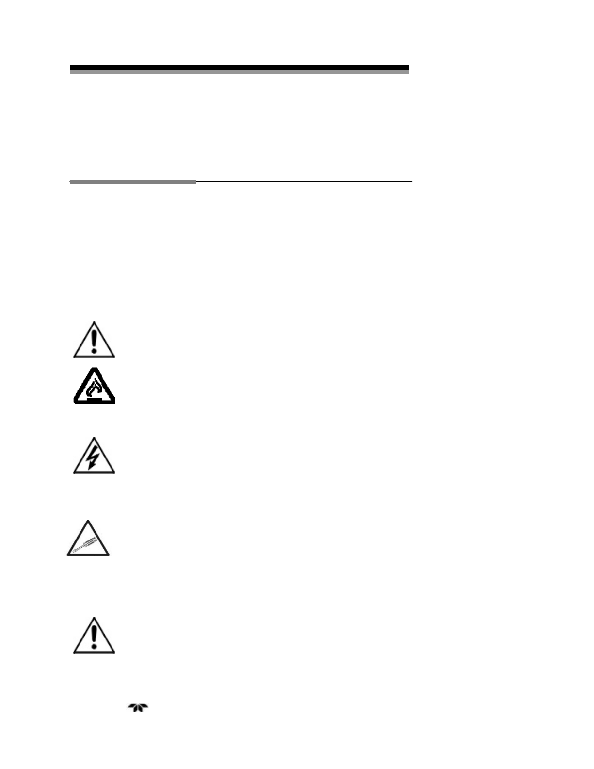
GENERAL WARNING/CAUTION: Refer to the instructions
for details on the specific danger. These cautions warn of
specific procedures which if not followed could cause bodily
Injury and/or damage the instrument.
CAUTION: HOT SURFACE WARNING: This warning is specific
to heated components within the instrument. Failure to heed the
warning could result in serious burns to skin and underlying
tissue.
WARNING: ELECTRICAL SHOCK HAZARD: Dangerous voltages
appear within this instrument. This warning is specific to an
electrical hazard existing at or nearby the component or
procedure under discussion. Failure to heed this warning could
result in injury and/or death from electrocution.
Technician Symbol: All operations marked with this symbol
are to be performed by qualified maintenance personnel only.
No
Symbol
CAUTION:
NOTE: Additional information and comments regarding a
specific component or procedure are highlighted in the form of a
note.
THE ANALYZER SHOULD ONLY BE USED FOR THE
PURPOSE AND IN THE MANNER DESCRIBED IN THIS
MANUAL.
Teledyne Analytical Instruments iv
Page 5

Thermal Conductivity Transmitter
IF YOU USE THE ANALYZER IN A MANNER OTHER
THAN THAT FOR WHICH IT WAS INTENDED,
UNPREDICTABLE BEHAVIOR COULD RESULT
POSSIBLY ACCOMPANIED WITH HAZARDOUS
CONSEQUENCES.
This manual provides information designed to guide you through the
installation, calibration operation and maintenance of your new analyzer.
Please read this manual and keep it available.
Occasionally, some instruments are customized for a particular
application or features and/or options added per customer requests. Please
check the front of this manual for any additional information in the form of
an Addendum which discusses specific information, procedures, cautions
and warnings that may be peculiar to your instrument.
Manuals do get lost. Additional manuals can be obtained from
Teledyne at the address given in the Appendix. Some of our manuals are
available in electronic form via the internet. Please visit our website at:
www.teledyne-ai.com.
Teledyne Analytical Instruments v
Page 6

2000 XTC
Table of Contents
List of Figures viii
List of Tables ix
Introduction………………………………………………………………1
1.1 Overview 1
1.2 Typical Applications 1
1.3 Main Features of the Transmitter 2
1.4 Operator Interface 2
Operational Theory……………………………………………………...5
2.1 Introduction 5
2.2 The Thermal Conductivity Sensor 5
2.3 Sample System 7
2.4 Electronics and Signal Processing 9
2.4.1 Transmitter 9
2.4.2 Galvanic Isolator 10
2.5 Connection Cable 11
Installation………………………………………………………………12
3.1 Unpacking the Transmitter 12
3.2 Mounting the Transmitter 13
3.3 Mounting the Interface Unit 13
3.4 Gas Connections 14
3.5 Electrical Connections 15
3.6 Calibration 17
3.6.1 Adjusting Internal Temperature 18
3.6.2 Zero Calibration 19
3.6.3 Span Calibration 20
Teledyne Analytical Instruments vi
Page 7

Thermal Conductivity Transmitter
Maintenance…………………………………………………………….22
4.1 Routine Maintenance 22
4.2 Troubleshooting 22
4.3 Fuse Replacement 24
Appendix………………………………………………………………...26
Specifications 26
Recommended Spare Parts List 28
Reference Drawings 28
Index……………………………………………………………………...29
Teledyne Analytical Instruments vii
Page 8

2000 XTC
List of Figures
Figure 1-1: XTC Transmitter Modules…………………………………..3
Figure 2-1: Thermal Conductivity Sensor ………………………………6
Figure 2-2: Recommended External Sample System…………………8
Figure 2-3: Internal Piping………………………………………………..8
Figure 2-4: Block Diagram of 2000 XTC………………………………..9
Figure 2-5: Model 2000 XTC External Wiring Diagram……………..11
Figure 3-1: Mounting Dimensions for Sensor Unit…………………...13
Figure 3-2: Mounting Dimensions for Interface Unit…………………14
Figure 3-3: Power and Output Connections to Galvanic Isolator…..16
Figure 3-4: Cable Connection to Galvanic Isolator Module…………16
Figure 3-5: Temperature and Calibration Adjustment Location…….18
Figure 4-1: Cable Identification in Transmitter………………………..24
Figure 4-2 Fuse Location………………………………………………25
Teledyne Analytical Instruments viii
Page 9

Thermal Conductivity Transmitter
List of Tables
Table 3-1: Heater Temperature…………………………………..19
Table 3-2: Concentration from Output Current………………….21
Table 4-1 Troubleshooting………………………………………...222
Table 4-2: Fuses……………………………………………………244
Teledyne Analytical Instruments ix
Page 10
2000 XTC
DANGER
COMBUSTIBLE GAS USAGE
This instrument is approved as an intrinsically safe gas
analyzer for usage in a category (ib) Group IIC hazardous area.
This approval applies only to the equipment specified and
installed in accordance with the information contained within
this manual. It is the customer's responsibility to ensure
safety, especially when combustible gases are being analyzed
since the potential of gas leaks always exists.
WARNING
The customer should ensure that the principles of operating of
this equipment are well understood by the user and that the
instrument as well as any approved support equipment is
properly installed. Misuse of this product in any manner,
tampering with its components, or unauthorized substitution of
any component may adversely affect the certification and
safety of this instrument.
Since the use of this instrument is beyond the control of
Teledyne, no responsibility by Teledyne, its affiliates, and
agents for damage or injury from misuse or neglect of this
equipment is implied or assumed.
Teledyne Analytical Instruments x
Page 11

Thermal Conductivity Transmitter Introduction
Introduction
1.1 Overview
The Teledyne Analytical Instruments 2000 XTC Thermal Conductivity
Transmitter is an instrument designed to analyze the gas concentration of a
binary gas mixture. This manual covers the CENELEC/ATEX approved
model 2000 XTC Thermal Conductivity Transmitter. These units are rated as
intrinsically safe and may be used in Class I, Group A, B, C, D, Div. 1 (North
America) and EEx ib IIC T3 (IEC/Europe) hazardous environments.
1.2 Typical Applications
The 2000 XTC Thermal Conductivity Transmitter is versatile. It is
capable of measuring the gas concentration of a species in a binary or
pseudo-binary mixture of gases over a concentration range. The specific
species and gas mixture as well as the analysis range employed is fixed
at the factory for your specific application. Typical applications for this
transmitter include:
Determining the gas concentration of a binary gas, for
•
instance, Ar or N2 in air
•
Analyzing the methane (CH4) concentration in natural gas
(80-100% CH4) sample
•
Analysis of H2 in various backgrounds
•
CO2 safety monitoring
•
Specific gas mixer and process control applications
•
Semiconductor manufacturing
•
Petrochemical process control
•
Quality assurance
Typical instrument ranges for this instrument include:
•
H2 in N2 (or air)
0-5%, 0-8%, 0-10%, 0-20%, 0-100%
Teledyne Analytical Instruments 1
Page 12

Introduction 2000 XTC
He in N2 (or air) •
0-5%, 0-8% 0-10%, 0-30%, 0-100%
Natural Gas in Methane
•
0-20%, 0-50%, 0-100%
Nitrogen (or air) in CO2
•
0-10%, 0-20%, 0-50%, 0-100%
1.3 Main Features of the Transmitter
The 2000 XTC Thermal Conductivity Transmitter is sophisticated
yet simple to use. It provides a 4-20 mA output signal proportional to
the concentration of one component of a gas mixture. The signal is
based on the difference between the thermal conductivity of the sampled
gas compared to calibration points. The main features of the analyzer
include:
Integral isolated safety barrier classified as intrinsically safe
•
for hazardous area use.
Nema 4X, IEC 60529 and IP 66 rated sensor housing
•
ATEX approved for EEx ib IIC T3 (Europe)
•
4-20 mA signal output proportional to the concentration of
•
one of the gases in the mixture.
Long-lifetime solid state thermal conductivity sensor
•
•
Temperature controlled cell block provides excellent zero
and span stability over a wide temperature range
•
Versatile analog signal processing IC.
•
Easy installation
1.4 Operator Interface
The user does not interact with the transmitter directly. The
standard 2000 XTC Thermal Conductivity Transmitter provides a 4-20
mA output signal proportional to the concentration of the gas being
analyzed. This signal can be used to drive devices such as displays,
concentration alarms, user-supplied devices, or it can be monitored
using a chart recorder.
Teledyne Analytical Instruments 2
Page 13

Thermal Conductivity Transmitter Introduction
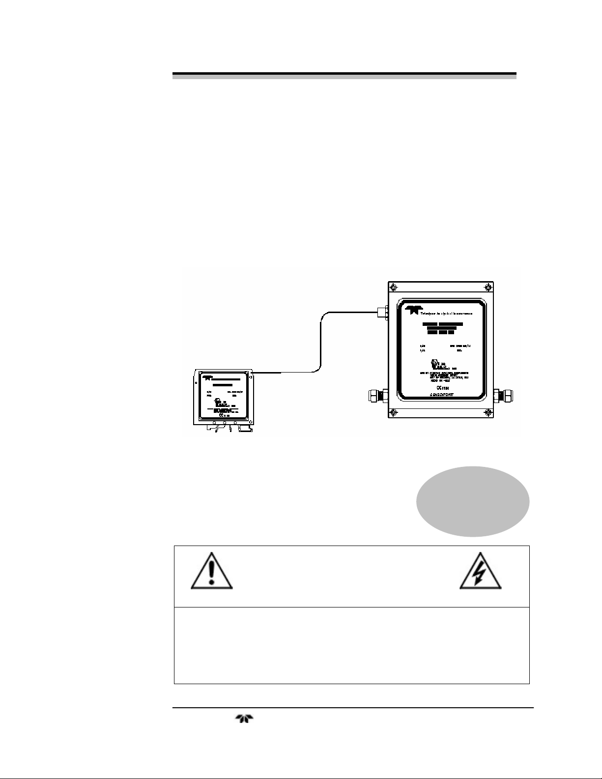
Figure 1-1 shows the 2000 XTC Thermal Conductivity Transmitter.
The instrument is comprised of two modules: the transmitter unit and the
galvanic isolator unit. The transmitter is located at the sample point
(which can be a hazardous area) and is where the sample gas input is
converted into an electrical output signal.
The galvanic isolator module contains the 24V power supply, the
power isolation safety barrier and signal output connection. This module
is used to provide safe power to the transmitter eliminating the danger of
ignition by sparks or heating due to excessive power.
Figure 1-1: XTC-Transmitter Modules
Teledyne Analytical Instruments 3
Page 14

Operational Theory 2000 XTC
Teledyne Analytical Instruments 4
Page 15

Thermal Conductivity Transmitter Operational Theory
Operational Theory
2.1 Introduction
The 2000 XTC is comprised of two subsystems:
1. The thermal conductivity sensor and transmitter
2. Galvanic isolator and power supply
The system directs a sample gas into the transmitter. Internally, the
sample is passed to the sensor and heated without contaminating or
altering the sample in any way. The thermal conductivity sensor is a
solid-state device that translates the amount of gas present in the sample
into a change in resistance (expressed in ohms). The electronic signal
processing and control circuits provide a linear output signal
compensated for ambient temperature fluctuations over a wide range.
Increased stability is achieved using integral heaters that control the
temperature of the sensor cell.
2.2 The Thermal Conductivity Sensor
The Thermal Conductivity Transmitter is designed to measure the
concentration of a component in a binary stream of gas. It can be used to
determine the concentration of a sample stream containing a composite
mixture of impurities by comparing the difference in thermal conductivity of
the sample stream with calibrated reference points.
Thermal conductivity measurements are non-specific by nature.
The thermal conductivity of a gas mixture depends on the conductivities
of the individual components of the mixture and their relative
concentration. The transmitter is calibrated at the factory to be linear
over the range and mixture of interest specified by the customer at the
time of purchase. In order to accurately detect and quantify a component
in a sample stream, the sample must be composed of the particular
component and background gas specified at the time of purchase. The
transmitter can be used with other binary gas mixtures, but the output
signal may or may not be linear across the sensor output range. Consult
the factory for additional information regarding the use of this
Teledyne Analytical Instruments 5
Page 16

Operational Theory 2000 XTC
instrument for analyzing other gas mixtures. Generally, the user must be
able to calibrate the instrument with a gas containing the host gas and a
known concentration of the impurity or gas to be analyzed. At a
minimum, a zero gas and a mixture containing approximately 70-100%
of the species to be analyzed on the range of interest should be provided
in order to properly calibrate this instrument.
Figure 2-1 shows a cross section of the sensor used in the 2000 XTC. A
resistor is mounted on a heated membrane to which the sample gas is
exposed. This resistor is used to both heat and measure the temperature of the
membrane. A second resistor is fabricated directly on the silicon and is used
to compensate for changes in the ambient temperature. Depending on the
sample gas density, exposing the sensor to the gas will either increase the
membrane temperature or decrease or the measuring resistor temperature.
Implementing each of the two resistors in the analog signal conditioning
stages enables the null point of the circuit to be directly related to the thermal
conductivity of the sample gas.
Figure 2-1: Thermal Conductivity Sensor
During calibration, the analog signal is balanced for the zero gas at
one end of the measurement range, and span gas at the other end. The
resulting electrical signal is fed to a microprocessor which linearizes the
output based on data programmed at the factory. An E-to-I converter
produces an isolated 4–20 mA DC current output spanning the analysis
range.
Teledyne Analytical Instruments 6
Page 17

Thermal Conductivity Transmitter Operational Theory
Control circuitry precisely regulates the temperature of the
measuring cell. These additional controlled heaters are installed to heat
the sample gas and compensate for ambient temperature fluctuations,
enhancing the stability and accuracy of the measuring process. The
heater temperature is adjustable using a set-screw adjustment
potentiometer inside the transmitter unit.
Control of the sample and supporting gases is not provided in the
basic design. TAI offers a variety of supporting gas control panels as
companion accessories to the analyzer to fill this need. In any case,
means must be provided for controlling the flow rates of sample and
calibration gas through the analyzer. A control manifold will be required
for the introduction of zero and span gas, as well as sample gas, into the
sample path. Appropriate pressure reducing regulators will have to be
installed at all gas supply sources; for those customers wishing to
incorporate their own sample controls, a recommended system piping
drawing is shown in Figure 2.2 and a reference drawing is included
among the drawings at the rear of the manual.
2.3 Sample System
A suitable external sample system must be provided by the
customer. The external sample system delivers calibration or sample gas
to the transmitter at suitable pressure and flow rate. Internally, the 2000
XTC uses a brass cell block with stainless steel tubing and connectors.
CAUTION: IT IS THE RESPONSIBILITY OF THE END-USER TO
ENSURE THAT THE GASES USED IN THIS
INSTRUMENT ARE COMPATIBLE WITH THE
MATERIALS USED IN THE SAMPLE SYSTEM. FAILURE
TO DO SO COULD RESULT IN PERSONAL INJURY AS
WELL AS DAMAGE TO THE INSTRUMENT.
The external sample system should be capable of supplying clean,
particulate-free and moisture-free sample gas to the transmitter. The
sample gas must be regulated between 2-20 psig. A flow control device
such as a flow meter with a needle valve should be incorporated to
maintain gas flow within 0.4-2 SCFH. It is convenient to install valves
in the sample system to allow switching between sample and calibration
gas. Figure 2-2 is a typical sample system for delivering sample and
calibration gases to the transmitter. It uses two (2) 3-way valves to
deliver either sample or calibration (zero or span) gas to the transmitter.
Teledyne Analytical Instruments 7
Page 18

Operational Theory 2000 XTC
Figure 2-2: Recommended External Sample System
The sample path within the transmitter is a straight-through path.
Gas encounters no dead space. This minimizes residual gas pockets that
can interfere with accurate analysis.
Stainless steel 1/4” tube fittings are installed (6mm are available)
for connecting the external sample system to the transmitter. For metric
system installations, 6 mm adapters can be supplied if needed. The
sample gas path through the transmitter is shown in Figure 2-3.
Figure 2-3: Internal Piping
Teledyne Analytical Instruments 8
Page 19

Thermal Conductivity Transmitter Operational Theory
2.4 Electronics and Signal Processing
For safety reasons, the electronics and signal processing section are
located remotely from the transmitter module. A galvanic isolator is
employed to limit the current that can be passed through the interconnect
cable to levels that are incapable of providing an ignition source. The
galvanic isolator also provides an optically-isolated 4-20 mA output
signal reconstructed from the 0-4 mA output signal sent from the
transmitter. All electronics in the transmitter are contain ed on a single
PC board accessible by removing the front cover. The transmitter is
powered from two (2) separate 15VDC lines from the galvanic isolator
module. The galvanic isolator incorporates a 24VDC power supply.
The processing electronics for the sensor are located inside the
transmitter case in addition to the sample cell heaters and E-to-I
converter. The control circuitry for the sample cell heaters, the 24 VDC
power supply, and electronics used to condition the output signal are
located in the galvanic isolator case. Figure 2-4 is a block diagram of the
instrument electronics.
Figure 2-4: Block Diagram of 2000 XTC
2.4.1 Transmitter
The differences in thermal conductivities of the sample gas provide
a small but detectable change in temperature of the resistive sensor
Teledyne Analytical Instruments 9
Page 20

Operational Theory 2000 XTC
membrane. The amount of voltage needed to offset the analog output
(i.e. to null the circuit when the resistance changes due to temperature
effects) is measured and applied. A preprogrammed microcontroller
with EPROM uses the offset voltage from the analog stages to generate
a linearized output voltage signal, which is then converted to a 0-4 mA
current. This signal is fed back to the galvanic isolator for conversion to
a standard 4-20 mA current, to be used as interface with the user’s
readout device or alarm circuit. The linearized output is based on
calibrations performed and adjustments made at the factory for the
specific application at hand.
Certain factors outside of the gas concentrations bear on the
accuracy of the thermal conductivity sensor. The major contributor
involves temperature deviations or transients from a baseline
temperature. For this reason, a pair of controlled heaters is used to fix
the operating temperature of the sample cell. The control circuitry is
capable of maintaining a temperature setting from 18°C to 67°C within
the operating range of the instrument (0 to 50°C). Electronics for the
temperature control are housed in the transmitter module. Power is
supplied to the heaters by pins 2-3 for heater #1 and 1-4 for heater #2 on
the 5-wire interconnection cable.
2.4.2 Galvanic Isolator
The purpose of the safety barrier is to limit power to and from the
transmitter to levels that are incapable of generating enough energy to
cause ignition in a flammable or explosive gas mixture. The galvanic
isolator accepts a 24 volt DC input and provides two separate and
isolated 15 volt DC power outputs, plus receiving a 0-4mA current input
from the transmitter. Both power outputs are mutually isolated and
comply with the CENELEC requirement intrinsically safe to 60V. The
output from the isolator supplies power to the two (2) heaters in the
transmitter. Additionally, it supplies power to the sensor and PC board
for the compensation circuitry within the transmitter.
Each output side of the galvanic isolator is protected with a series
200mA fuse. A pair of zener diodes limits the open circuit voltage to
below 18V and short circuit current to 503mA or less. Power
fluctuations are reduced at the input side of the 24V input transformer
using a crowbar network of diodes.
Teledyne Analytical Instruments 10
Page 21

Thermal Conductivity Transmitter Operational Theory
The 24 VDC input is fed to the primary side of an input transformer.
The input circuit is fused via a 400 mA fuse and incorporates a diode
protection circuit in case of accidental reverse polarity connection.
The signal output is also fused, with a 50 mA fuse protecting the 420 mA output terminal. This terminal is also isolated using a high
linearity optocoupler with its own power-limiting circuitry.
Schematic diagrams for both the transmitter and galvanic isolator
are included in the drawing section of the Appendix.
2.5 Connection Cable
The interconnection between the safety barrier and transmitter
modules is accomplished with a 5-wire cable supplied as part of the
instrument. The transmitter end of the cable is fitted with an ATEX
approved 5-wire connector which can only be inserted in one
orientation. The other end of the connector is wired directly to the rear
of the galvanic isolator module. The wiring diagram for the galvanic
isolator is shown in Figure 2-5.
The 5-wire interface cable delivers power to the two heaters and the
electronics board. It also carries the 0-4 mA output signal from the
transmitter back to the galvanic isolator unit. Figure 2-5 shows the pin
configuration for this cable. The interface unit and the transmitter
module can be separated up to 30.5 meters (100 feet).
Figure 2-5: Model 2000 XTC External Wiring Diagram
Teledyne Analytical Instruments 11
Page 22

Installation 2000 XTC
Installation
For Intrinsically Safe (IS) installation, special considerations are
required. The 2000 XTC Thermal Conductivity Transmitter has been
designed to be Intrinsically Safe using an integral galvanic isolator module
that limits power to and from the transmitter in a ha zardous location. When
properly installed, this design utilizes redundant safety features to prevent
the transmitter from becoming an ignition source in the ev ent of a circuit
failure. There are various regulations and specifications relating to
intrinsically safe instrumentation and the user shou ld consult w ith the
proper certifying agency prior to installation. Using the integral galvanic
isolator reduces the possibility of fires or explosion stemming from power
circuitry associated with the transmitter in hazardous lo cations by limiting
the energy available for ignition. This instrument must be installed properly
and all cables, wires, connectors and solenoid valves (if equipped) must be
approved by the proper certifying agency. The configuration and associated
approval of this unit is based on the user’s application as specified at the
time of purchase. Consult the spare parts list in this manual or the factory
for approved replacement parts for this instrument.
Installation of the 2000 XTC Thermal Conductivity Transmitter
includes:
Unpacking •
•
Mounting
•
Gas connections
•
Electrical connections
•
Calibration
3.1 Unpacking the Transmitter
The transmitter is shipped with all the materials needed to install
and prepare the system for operation. Carefully unpack the transmitter
and inspect it for damage. Immediately report any damage to the
shipping agent.
Teledyne Analytical Instruments 12
Page 23

Thermal Conductivity Transmitter Installation
3.2 Mounting the Transmitter
The Model 2000 XTC Transmitter is intended for indoor use only.
The transmitter module is designed for operation in a hazardous
location. It should be mounted in an area close to the sample takeoff point. Refer to Figure 3-1 for mounting information and
dimensions. The calibration and temperature control adjustment
potentiometers are located under the top cover of the transmitter.
This should be taken into consideration when determining mounting
location. Also make sure there is adequate room to make the sample
system connections. Once a suitable location has been determined,
flush-mount the transmitter using the holes provided in the case.
Figure 3-1: Mounting Dimensions for Sensor Unit
3.3 Mounting the Interface Unit
The galvanic isolator module or interface unit must be located
indoors in a general-purpose location. It can safely be located up to 30.5
meters from the transmitter. This module can either be DIN rail mounted
or panel mounted. The dimensions for this module are shown in Figure
3-2.
Teledyne Analytical Instruments 13
Page 24

Installation 2000 XTC
Figure 3-2: Mounting Dimensions for Interface Unit
Once the transmitter and galvanic isolator are securely mounted,
connect the interface cable to the transmitter. If the cable is not attached
to the safety barrier, connect the wires to the unit as described in Section
3-5. The transmitter end of the cable is fitted with a 5-pin connector.
Secure the cable to the mating connector on the transmitter.
3.4 Gas Connections
The unit is manufactured with 1/4-inch stainless steel tube fittings
for the inlet and outlet gas connections. Refer to Figure 2.2 in Section
2.3 for a recommended sample system.
1. Insert the tube into the tube fitting, and finger-tighten the nut
until the tubing in the fitting cannot be rotated freely by hand.
(This may require an additional 1/8 turn beyond finger-tight.)
2. Hold the fitting body steady with a backup wrench, and with
another wrench rotate the nut another 1-1/4 turns.
Note: Do not crimp or bend the tubing when attaching to the
transmitter.
Teledyne Analytical Instruments 14
Page 25

Thermal Conductivity Transmitter Installation
CAUTION: THIS INSTRUMENT IS DESIGNED TO HANDLE
HAZARDOUS GASES. WHENEVER A FITTING IS
OPENED, USE A NEW FERRULE AND CONE TO
SECURE A GAS TIGHT SEAL. EACH FITTING MUST
BE LEAK CHECKED WHENEVER A CONNECTION
HAS BEEN OPENED OR DISTURBED IN ANY
MANNER.
The inlet gas pressure should be regulated between 2-20 psig. A
flow control device should be installed before the “sample in” port in
order to keep the gas flow between 0.4 and 2 SCFH.
If greater flow is required for improved response time (over 20
SCFH), install a bypass in the sampling system upstream of the analyzer
input.
Exhaust connections must be consistent with the hazard level of
the constituent gases. Check local, state, and federal laws, to ensure
the exhaust stream vents to an appropriately controlled area if
required. The exhaust should be vented to atmospheric pressure or
returned to the process line. Use care not to create backpressure in
the vent line.
3.5 Electrical Connections
The Thermal Conductivity Transmitter requires three electrical
connections:
24 VDC power input •
•
Signal output (4-20 mA current output)
•
Interconnection cable
Power and output signal connections are made to the galvanic
isolator module according to the interconnection diagram C-74837
included at the back of this manual. See also Figure 3-3.
24VDC Power Connection
The 24VDC power supply can deliver a maximum of 10.8 watts to
power the heaters and drive the electronics in both the galvanic isolator
and the transmitter modules. Connect the positive lead from the 24 VDC
source to terminal 7 and the negative lead to terminal 8 on the galvanic
isolator module as shown in Figure 3-3.
Teledyne Analytical Instruments 15
Page 26

Installation 2000 XTC
4-20 mA Output Signal
The output signal from the instrument is available to the user as a
4-20 mA current. It has a maximum impedance of 700 Ohms. Typically,
this output is used to display concentration using a digital meter or chart
recorder or to trigger an alarm circuit. Referring again to Figure 3-3,
connect the positive lead to terminal 12 and the negative lead to terminal
11 on the galvanic isolator module.
Figure 3-3: Power and Output Connections to Galvanic Isolator
Module
Interface Cable
The interconnection cable is a 5-wire cable which delivers power to
the heaters and drives the electronics in the transmitter module. It also
passes a 0-4 mA linearized signal back from the sensor circuit to the
galvanic isolator module for output processing. To connect the cable,
insert the 5-pin connector end of the cable to the mating connector on
the transmitter. Connect the other end to the galvanic isolator according
to the diagram in Figure 3-4.
Figure 3-4: Cable Connection to Galvanic Isolator Module
CAUTION: THIS INSTRUMENT MEETS OR EXCEEDS THE
REQUIREMENTS FOR CENELEC APPROVAL AS AN
INTRINSICALLY SAFE APPARATUS. IN ORDER TO
MAINTAIN COMPLIANCE AND TO ENSURE THE
CONTINUED SAFE OPERATION OF THIS
Teledyne Analytical Instruments 16
Page 27

Thermal Conductivity Transmitter Installation
INSTRUMENT USE ONLY AN APPROVED
INTERCONNECTION CABLE. SEE THE SPARE
PARTS LIST IN THE APPENDIX OF THIS MANUAL
FOR AN APPROVED FACTORY REPLACEMENT
CABLE.
For intrinsically safe installat ion, use only the cable supplied by the
factory. Run length should not exceed 30.5 meters (100 ft).
3.6 Calibration
Note: Calibration frequency of the 2000XTC is highly dependent
on gas application. The recommended frequency is once
per month, although specific applications may be able to
go longer without required calibration. Perform calibration
procedure as required for your application, or contact the
manufacturer for more information.
Once the modules have been properly installed and wiring is
secure, check the following before calibrating the transmitter:
Make sure that suitable sources of zero and span gas are
•
connected to the transmitter either via a switching manifold
or separately (zero followed by span gas). See section 2.3.
Check the integrity and accuracy of the gas connections.
•
Make sure there are no leaks.
Verify that the modules have been properly installed and
•
wiring is secure.
•
Check that inlet sample pressure and flow rate is within the
accepted range (see section 3.3).
Calibration involves setting the zero level followed by setting the
span of the instrument. Zero and span potentiometers are located under
the cover of the transmitter on the PC board as shown in Figure 3-5.
The following calibration procedures assume that suitable
calibration gas connections have been made and that a read-out device
capable of interpreting a 4-20 mA current is attached to the output
terminals of the galvanic isolator module (see Section 3-5).
Teledyne Analytical Instruments 17
Page 28

Installation 2000 XTC
Figure 3-5: Temperature and Calibration Adjustment Location
3.6.1 Adjusting Cell Block Temperature
Note: A separate heater inside the transmitter case controls the
transmitter cell block temperature. It has been adjusted at
the factory for optimum performance based on your
application. Depending on the location of the transmitter
and your process application, it may be necessary to
adjust the temperature of the internal heaters. If
temperature adjustment is necessary proceed with the
following steps, if not, skip this section and proceed with
Zero Calibration. Remove the 4 screws securing the
transmitter cover and lift off the top cover.
To adjust the internal temperature of the transmitter:
1. Allow span gas to flow into the transmitter. Set the flow rate
of the zero gas to between 0.4 and 2 SCFH. As the span gas
is flowing through the instrument, check the output for a
stable reading.
2. If the output is varying over time, increase the temperature of
the internal heater. Using a small flat blade screwdriver, turn
the adjustment screw (R21) clockwise to increase the heater
temperature or counterclockwise to reduce the internal
temperature. The heater set temperature can be measured on
the board at U1 pin 12 (see Table 3.1). Allow 15 minutes for
Teledyne Analytical Instruments 18
Page 29

Thermal Conductivity Transmitter Installation
stabilization of the heater before continuing with the
calibration.
3. If the output is still fluctuating after 15 minutes, continue
making small adjustments to the temperature until the output
signal stabilizes.
Table 3-1: Concentration from Output Current
Heater
Temperature
(°C)
20°
25°
30°
35°
40°
45°
50°
55°
60°
65°
Voltage at U1
pin 12 (V)
2.04 V
2.25 V
2.45 V
2.62 V
2.78 V
2.92 V
3.04 V
3.15 V
3.24 V
3.32 V
3.6.2 Zero Calibration
Zero calibration requires the use of a prepared gas known to be free
of the gas species to be analyzed. If possible, the calibration gas should
be the background gas used in your application.
Note: This instrument was assembled and calibrated at the
factory using a specific background gas determined at the
time of purchase to be representative of the customer’s
application. Specific data has been pre-programmed into
the transmitter that is used by the system to linearize the
output signal generated by the sensor. If a different gas is
used, the resulting output signal may not be linear with
concentration. You also may experience difficulty in
Teledyne Analytical Instruments 19
Page 30

Installation 2000 XTC
zeroing this instrument when using a gas different than the
gas specified at the time of purchase.
To zero calibrate this instrument:
1. Connect a read-out device to the 4-20 mA output signal
terminals on the galvanic isolator module according to
Section 3-5.
2. If the transmitter cover has not been removed, unscrew the 4
cover screws and remove the top cover.
3. Allow zero gas to pass into the transmitter. The pressure
should be regulated between 2-20 psig and the flow set
between 0.4 –2 SCFH.
Note: It may be necessary to purge the sample line and
transmitter with zero gas for several minutes before
obtaining a stable zero reading.
4. The output should read the zero gas value or 4 mA. If not,
adjust the zero potentiometer (R8) on the PC board using a
thin blade screwdriver until the reading is the zero gas value
or 4 mA.
5. It may be necessary to recalibrate the zero after span
calibration.
3.6.3 Span Calibration
Span calibration requires the use of a prepared gas mixture
containing a known concentration of the gas species to be analyzed in a
background gas. An acceptable span gas concentration is 70-100% of
the anticipated analysis range.
Note: This instrument was assembled and calibrated at the
factory using a specific gas mixture determined at the time
of purchase to be representative of the customer’s
application. Specific data has been pre-programmed into
the transmitter that is used by the system to linearize the
output signal generated by the sensor. If a different gas is
used, the resulting output signal may not be linear with
concentration. You also may experience difficulty in span
calibrating this instrument when using a gas different than
the gas specified at the time of purchase.
Teledyne Analytical Instruments 20
Page 31

Thermal Conductivity Transmitter Installation
To span calibrate this instrument:
1. Connect a read-out device to the 4-20 mA output signal
terminals on the galvanic isolator module according to
Section 3-5.
2. If the transmitter cover has not been removed, unscrew the 4
cover screws and remove the top cover.
3. Allow span gas to flow through the transmitter. After a few
moments, the output device should respond to the known
concentration of gas in the span gas mixture.
4. If the read-out device indicates a value different than the
known concentration, adjust the span potentiometer (R38) as
shown in Figure 3-5 until the readout is correct. If using a
mA current read-out device, refer to Table 3-1 to determine
concentration from the output current.
5. If the zero calibration must be changed after initial span
calibration, recalibrate the span.
Table 3-2: Concentration from Output Current
Concentration
Current
Output
(mA)
4 0 0 0 90 0
5.6 0.1 1 5 91 10
7.2 0.2 2 10 92 20
8.8 0.3 3 15 93 30
10.4 0.4 4 20 94 40
12.0 0.5 5 25 95 50
13.6 0.6 6 30 96 60
15.2 0.7 7 35 97 70
16.8 0.8 8 40 98 80
18.4 0.9 9 45 99 90
0-1%
Full
Scale
0-10%
Full
Scale
0-50%
Full
Scale
90-100%
Full
Scale
0-100%
Full
Scale
20 1.0 10 50 100 100
Teledyne Analytical Instruments 21
Page 32

Maintenance 2000 XTC
Maintenance
4.1 Routine Maintenance
Aside from normal cleaning and checking for leaks at the gas
connections, routine maintenance is limited to recalibration. For
calibration procedures, refer to Section 3.6. On occasion, it may be
necessary to replace a blown fuse. This is covered in section 4.2.
WARNING: SEE WARNINGS ON THE TITLE PAGE OF THIS
MANUAL.
The overall design of the instrument is intended to facilitate servicing
and troubleshooting, should that ever be necessary. The sensor itself is a
solid-state unit with no serviceable parts. The cell is enclosed in an
insulated compartment that is readily acces sible after r emoving the
transmitter cover. There are three (3) PC boards handling the electronics:
one in the transmitter module and two in the galvanic isolator module. Both
boards are easily accessible after removing the respective front covers.
4.2 Troubleshooting
The following table offers guidelines for diagnosing and correcting
common problems associated with the 2000 XTC Thermal Conductivity
Transmitter.
Table 4-1 Troubleshooting
Symptom Cause Remedy
The unit will not
power up.
Power not connected
or a wire has pulled
loose.
A) Make sure 24VDC power
is connected and turned
on.
B) Check input power wiring
at rear of galvanic isolator
module.
Teledyne Analytical Instruments 22
Page 33

Thermal Conductivity Transmitter Maintenance
Symptom Cause Remedy
No output signal
Erratic output signal Instrument out of
Blown fuse on input
power circuit.
Blown fuse
Cable disconnected
or broken
Problem with external
read-out device
calibration or
improperly calibrated
Check fuse and replace if
necessary with 400 mA
fuse. See Section 4.3.
A) Check fuse on signal
output circuit. Replace if
necessary with 50 mA
fuse. See Section 4.3.
B) Check fuse on output
power circuit. Replace if
necessary with 200mA
fuse. See Section 4.3.
Check power cable in
transmitter module. See
Figure 4.1.
Check external si gnal read-
out device connection.
A) Recalibrate instrument
with known calibration
gases.
B) Use appropriate calibration
gas
Temperature
instability inside
transmitter case
Loose cable
connection
Damaged sensor
A) Adjust heater temperature
and recalibrate. See
Section 3.6.1.
A) Check interconnection
cable.
B) Check heater cable. See
Figure 4.1.
C) Check sensor cable. See
Figure 4.1.
A) Replace sensor. Contact
factory.
Teledyne Analytical Instruments 23
Page 34

Maintenance 2000 XTC
Figure 4-1: Cable Identification in Transmitter
4.3 Fuse Replacement
There are four fuses installed in the galvanic isolator module for
circuit protection. The main fuse (F1) is accessible after removing the fuse
holder cover. All other fuses require separating the 2 galvanic isolator
modules. See Figure 4-2 for fuse identification. Table 4-1 lists the fuse
rating, TAI part number, and the applicable circuit it serves to protect.
Table 4-2: Fuses
Fuse Circuit Fuse
Rating
F1 24 VDC
Main Power
F2 &
F3
F4 Output Signal 50 mA
Heater Circuit /
Transmitter Power
400 mA
FastActing
5x20
160 mA
FastActing
5x20
FastActing
5x20
TAI P/N
F1668
F1697
F1670
Teledyne Analytical Instruments 24
Page 35

Thermal Conductivity Transmitter Maintenance
To replace the main power fuse (F1):
Disconnect power to the instrument •
•
Use a flat blade screwdriver to remove the fuse holder cover.
Push in with the screwdriver and turn counterclockwise.
•
Pull out the blown fuse and replace with an exact
replacement according to Table 4-2.
•
Replace cover and power up instrument.
Figure 4-2 Fuse Location
To remove the other fuses:
Disconnect power to the instrument. •
•
Remove the interface unit from the mounting rail or
enclosure
•
The two galvanic isolators snap together. Separate the two by
gently pulling the top section while holding the bottom
section.
•
Gently pry out the blown fuse and replace with an exact
replacement according to Table 4-2.
•
Reassemble the isolator modules and reinsert the assembly
into its housing or mounting rail.
Teledyne Analytical Instruments 25
Page 36

Appendix 2000 XTC
Appendix
Specifications
System: Dual module: transmitter and galvanic
isolator
Enclosure: Galvanic isolator: plastic DIN
mountable case
Transmitter: aluminum case, panel
mountable, Nema 4X, IEC 60529 and IP
66 rated
Classification: ATEX EEx ib IIC T3 (Europe)
Power Requirements: 24VDC, 10.8 watt max power
consumption (8 watts normal)
Ranges: Specific application determined by user.
See Section 1.2 for example ranges.
Sensor: Thermal conductivity sensor (Microsens
MTCS 2201)
Accuracy: ± 2% of full scale at constant temperature
and pressure, ± 5% over 0–50°C range.
Response Time: 10-90% of signal level in less than 30
seconds
Operating Temperature: 0–50°C
Signal Output: 4–20 mA DC linear
Max Load Impedance: 700 Ohms
Sample System: Brass cell block with stainless steel tubing
and 1/4 inch connectors
Pressure: 2-3 psig min inlet pressure
Teledyne Analytical Instruments 26
Page 37

Thermal Conductivity Transmitter Appendix
Flow Rate 0.4-2.0 SCFH
Internal Heater: 2—1.5W heaters
Temp Control: Factory set to 20 ± 2°C
User settable
Calibration Controls: Zero, span and temperature control
Fuses: Input power circuit: 400 mA
Output Signal Circuit: 50 mA
Heater Circuit: (2) 160 mA
Mounting (transmitter): Wall-mount (see section 3.2)
Mounting (interface unit): DIN-rail mounting (see section 3.3)
Teledyne Analytical Instruments 27
Page 38

Appendix 2000 XTC
Recommended Spare Parts List
Qty. Part Number Description
1 U2 Bulkhead compression fitting, 1/4” tube
1 C74627 Galvanic isolator board #1
1 C74632 Galvanic isolator board #2
1 C73750 T/C Transmitter Board
1 A74933 T/C Sensor Assembly
1 B74934 Cable assembly, interconnect
4 F1668 Fuse, Fast-acting 5mm x 20mm, 400 mA
4 F1697 Fuse, Fast-acting 5mm x 20mm, 160 mA
4 F1670 Fuse, Fast-acting 5mm x 20mm, 50 mA
2 R2157 ¼” to 6mm tubing adapter SS
A minimum charge is applicable to spare parts orders.
Note: Orders for replacement parts should include the part
number (if available) and the model and serial number of
the instrument for which the parts are intended.
Orders should be sent to:
TELEDYNE Analytical Instruments
16830 Chestnut Street
City of Industry, CA 91749-1580
Phone (626) 934-1500, Fax (626) 961-2538
Web: www.teledyne-ai.com
or your local representative.
Reference Drawings
C74836 Outline Diagram
C74837 Interconnection Diagram
C74838 Final Assembly Drawing
B74934 Cable Assembly, Interconnect
Teledyne Analytical Instruments 28
Page 39

Thermal Conductivity Transmitter Index
Index
accuracy 10, 26
address 28
adjustment location 18
analog signal 6
analog stages 10
analysis range 1, 6
applications 1
ATEX 1
background gas 5
binary gas mixture 5
block diagram 9
bypass line 15
cable See interface cable
cable identification 24
cable run length 17
calibration 5, 6, 17
internal temperature 18
span 20
zero 19
calibration controls 27
calibration point 5
calibration points 2
caution sign iv
cell block 2, 7, 26
chart recorder 2
classification 26
combustible gas warning x
concentration alarm 2
constant temperature 10
control circuit 5, 7
copyright ii
crowbar network 10
current limiting 9
dead space 8
display 2
drawings 28
E to I converter 6, 9
EEx ib IIC T3 1
electrical connections 15
enclosure 26
external sample system See sample
system
factory calibration 10
features 2
figures listing viii
flow control 7, 15
flow rate 7, 15, 26
fuse 10, 24, 27
fuse location 25
fuse replacement 24
galvanic isolator 3, 5, 9, 10, 11, 12, 16,
22
gas compatibility 7
gas connection 14
gas density 6
gas mixture 1
hazardous location 12
heated membrane See membran e
heater 5, 7, 9, 10, 11, 18, 26
ignition source 12
impedance 16, 26
input 10
input transformer 11
installation 12
interface cable 10, 11, 14, 16
interface cable connection 16
internal temperature adjustment 18
intrinsically safe 1, 10, 12, 17
leak check 15
linear 5, 6
linearized output 10
manuals, additional v
Melexis chip 10
membrane 6, 10
microprocessor 6
model information iii
mounting dimensions 13
null point 6
offset voltage 10
open circuit voltage 10
operating range 10
operating temperature 26
opto-coupler 11
output connections 16
output current 21
Teledyne Analytical Instruments 29
Page 40

Index 2000 XTC
output signal 2, 5, 6, 10
0-4 mA 9, 11, 16
4-20 mA 9, 16
PC board 9, 17, 22
pin configuration 11
potentiometer 7, 13, 17
power fluctuation 10
power limiting 10
power output 10
power requirements 26
power supply 3, 5, 9, 15
pressure 26
pressure regulation 7, 15
purge 19
reference See calibration point
reference drawings See drawings
regulator 7
resistance 5
resistor pair 6
response time 15, 26
routine maintenance 22
safety barrier 3
safety information iv
sample path 8
sample system 7
sensor 2, 5, 6, 9, 10, 16, 26
sensor membrane See membrane
serial number iii
short circuit current 10
signal output 26
signal processing 5, 9
span gas 6
span potentiometer See potentiometer
spare parts 28
spare parts listing 28
specifications 26
stability 5, 7
subsystem 5
tables listing ix
technician symbol iv
Teledyne address 28
temperature compensation 5, 6, 7
testing 17
thermal conductivity 5, 6, 9
thermal conductivity sensor See sensor
transmitter 3, 5, 13, 22
power 9
troubleshooting 22
valve
switching 7
warning sign iv
warranty ii
web address 28
website address v
wiring diagram 11
zener diode 10
zero gas 6
zero potentiometer See potentiometer
Teledyne Analytical Instruments 30
 Loading...