

Page 1
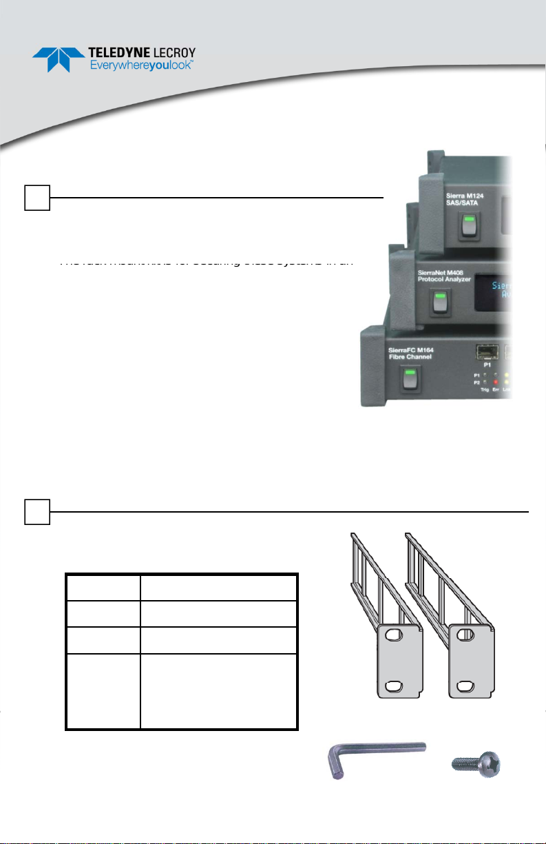
Rack Mount Installation Guide
The rack mount kit is for securing these systems in an
SierraNet
™ M408 and
SierraFC
™ M164
(for securing the
l
1U Height Systems
1
Introduction
This manual describes the procedure to retrofit protocol
analysis 1U-sized systems for rack mounting at your site.
EIA 310-D 19-inch equipment rack. The rack mount kit
is included with some systems, or may be purchased
as an accessory for existing systems.
Two brackets, which are attached (as shown in this
document) to the side of the chassis, connect the
chassis to the mounting posts of the rack.
Some racks provide a power strip along the length
of one of the rear posts. If your rack has this feature,
the systems and the rack mounting brackets are
designed so that power can be supplied to the rear of the unit while network cables
and user control is available at the front (exposed) portion of the system.
Rack Mount Kits covered by this document include kits for the Sierra™ M124,
.
2
Rack Mount Kit Components
The kit includes the following components:
Quantity Part Description
2 Rack Mount Brackets
1 9/64” Allen Key
4 10-32 x 0.5 Screws
system chassis to the
rack)
You will also need the following
additional tools:
• Tape Measure
•Leve
• Phillips Screwdriver
2 Rack Mount Brackets
4 x Screws1 x Allen Key
Page 2
3
Planning
the
Installation
Most
rack
mounts
conformtothe
/
(
)ad
5/8(5
8
),
/( )ad5/8(58 ),
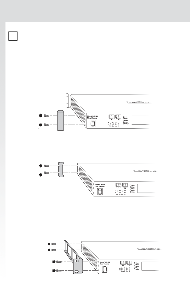
Installing the Rack Mount Brackets
Take the following steps to attach the two brackets to the system chassis:
Step 1: Place the system chassis on a sturdy surface.
Step 2: Using the 9/64” Allen Key provided, unscrew the two screws that
attach one of the front rubber bumpers to the system enclosure (see
illustration below). Keep these screws as they will be used to attach
the new rack mount brackets (see Steps 6-7).
Step 3: Repeat this procedure to remove the other front rubber bumper.
Step 4: Remove the two screws that attach one of the rear rubber bumpers to
the system enclosure (see illustration below):
Note: The SierraFC M164
is used as an example in
these illustrations. The steps
are identical for other 1U systems.
Step 5: Repeat this procedure to remove the other rear rubber bumper.
Step 6: Attach one of the brackets (shown below) to the left side of the system
chassis using the 9/64” Allen Key provided and four of the screws that
previously attached the rubber bumpers (these are the screws that
were removed in Steps 2-5). See illustration below.
Page 3
Step 7: Attach the other bracket to the right side of the system chassis (using
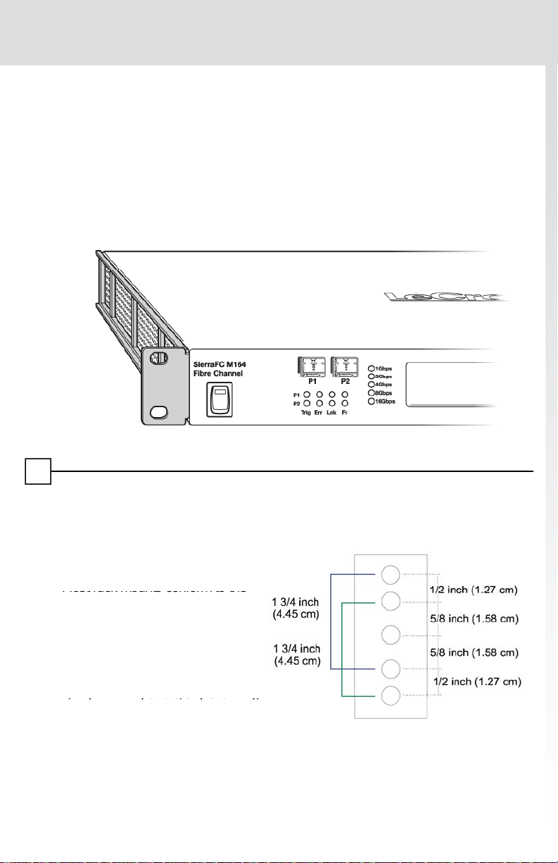
Planning the Installation
Most rack mounts conform to the
/
5/8” (15.8
/( )ad5/8(58 ),
the remaining four screws that were removed).
Note: Store the four rubber feet removed from the system in case you would
like to return the system to the original configuration at a later time.
4
Installing the system chassis in a rack mount enclosure requires some planning for
issues such as location, spacing, airflow and power supply. These issues are
reviewed below.
Location
EIA 310-D (RETMA) standard,
which provides mounting holes on
two vertical support rails which are
separated by 19” (480 mm). This
standard provides separation of the
spacing holes in increments of both
2” (12.7 mm) and
1
which allows for various multiples
of these spacing distances (such
as 1.75” [44.5 mm] which is
obtained by the separation of two 5/8” gaps and one 1/2” gap). See the diagram
on the right. The rack mount brackets supplied use 1.75” spacing.
mm),
Page 4
4
first be installed from the bottom, with the heaviest components
S
yq p(
,
,)
py p y
Step 3:
Make sure that your path to the rack is unobstructed
screws on each side of the unit
Use a Phillips screwdriver to tighten the
system
chassis
to
the
y
•
Phillips
Screwdriver
y
Planning the Installation (continued…)
WARNING: In order to provide stability to the rack, systems should
located in the bottom of the rack. If the rack is provided with
stabilizing devices, install the stabilizers before mounting or
servicing the unit in the rack.
A location for the system chassis should be planned taking these restrictions into
consideration.
pacing and Airflow
Allow, at a minimum, 1“ of air space around each side of the system, and 3-4” of
space in the rear of the system. This allows adequate airflow to cool the system.
The air temperature within the rack enclosure should not exceed 122°F (50°C).
Power Supply
The system requires a source of AC power (100-240V, 50-60 Hz, 230W) routed to
the rear of the system. All other controls and wiring connections are located on the
front panel of the system.
5
Installing the System Chassis into the Rack
Follow these steps to install the system chassis in an open rack that enables you
to slide the chassis in from the front.
Step 1: Position the chassis in the rack as follows:
Step 2: Use your tape measure and level to ensure that the supporting shelf and
the chassis are installed straight and level.
Step 4: Slide the unit into the rack and position using the attached L brackets so
that the slots in the brackets are positioned over the appropriate
mounting holes in the side rails of the rack.
Step 5: Securely fasten the unit into the rack by using the four 10-32 x 0.5
screws which are supplied with the rack mount kit, installing two of the
.
screws.
This concludes the rack mount installation.
.
PN: 920060-00 Rev B
v0812
 Loading...