

Page 1

Instruction Manual
Model 1220
Multi - Channel
Combustible
Monitor
DANGER
HIGHLY TOXIC AND OR FLAMMABLE LIQUIDS OR GASES MAY BE PRESENT IN THIS MONITORING
SYSTEM.
PERSONAL PROTECTIVE EQUIPMENT MAY BE REQUIRED WHEN SERVICING THIS SYSTEM.
HAZARDOUS VOLTAGES EXIST ON CERTAIN COMPONENTS INTERNALLY WHICH MAY PERSIST
FOR A TIME EVEN AFTER THE POWER IS TURNED OFF AND DISCONNECTED.
ONLY AUTHORIZED PERSONNEL SHOULD CONDUCT MAINTENANCE AND/OR SERVICING. BEFORE
CONDUCTING ANY MAINTENANCE OR SERVICING CONSULT WITH AUTHORIZED SUPERVISOR/
MANAGER.
P/N M68325
ECO: #00-0203
05/25/2000
Teledyne Analytical Instruments
i
Page 2

Copyright © 1999 Teledyne Analytical Instruments
All Rights Reserved. No part of this manual may be reproduced, transmitted, transcribed, stored in a retrieval system, or translated into any other language or computer
language in whole or in part, in any form or by any means, whether it be electronic,
mechanical, magnetic, optical, manual, or otherwise, without the prior written consent of
Teledyne Analytical Instruments, 16830 Chestnut Street, City of Industry, CA 91749-1580.
Warranty
This equipment is sold subject to the mutual agreement that it is warranted by us free
from defects of material and of construction, and that our liability shall be limited to
replacing or repairing at our factory (without charge, except for transportation), or at
customer plant at our option, any material or construction in which defects become
apparent within one year from the date of shipment, except in cases where quotations or
acknowledgments provide for a shorter period. Components manufactured by others bear
the warranty of their manufacturer. This warranty does not cover defects caused by wear,
accident, misuse, neglect or repairs other than those performed by Teledyne or an authorized service center. We assume no liability for direct or indirect damages of any kind and
the purchaser by the acceptance of the equipment will assume all liability for any damage
which may result from its use or misuse.
We reserve the right to employ any suitable material in the manufacture of our
apparatus, and to make any alterations in the dimensions, shape or weight of any parts, in
so far as such alterations do not adversely affect our warranty.
Important Notice
This instrument provides measurement readings to its user, and serves as a tool by
which valuable data can be gathered. The information provided by the instrument may
assist the user in eliminating potential hazards caused by his process; however, it is
essential that all personnel involved in the use of the instrument or its interface, with the
process being measured, be properly trained in the process itself, as well as all instrumentation related to it.
The safety of personnel is ultimately the responsibility of those who control process
conditions. While this instrument may be able to provide early warning of imminent danger,
it has no control over process conditions, and it can be misused. In particular, any alarm or
control systems installed must be tested and understood, both as to how they operate and
as to how they can be defeated. Any safeguards required such as locks, labels, or redundancy, must be provided by the user or specifically requested of Teledyne at the time the
order is placed.
Therefore, the purchaser must be aware of the hazardous process conditions. The
purchaser is responsible for the training of personnel, for providing hazard warning
methods and instrumentation per the appropriate standards, and for ensuring that hazard
warning devices and instrumentation are maintained and operated properly.
Teledyne Analytical Instruments (TAI), the manufacturer of this instrument,
cannot accept responsibility for conditions beyond its knowledge and control. No statement expressed or implied by this document or any information disseminated by the
manufacturer or its agents, is to be construed as a warranty of adequate safety control
under the user’s process conditions.
ii
Teledyne Analytical Instruments
Page 3

Specific Model Information
The instrument for which this manual was supplied may incorporate
one or more options not supplied in the standard instrument. Commonly
available options are listed below, with check boxes. Any that are incorporated in the instrument for which this manual is supplied are indicated by a
check mark in the box.
Instrument Serial Number: _______________________
Options Included in the Instrument with the Above Serial Number:
Dual-Sensor
A second sensor PCB is installed to allow the Channel
Module(s) to monitor two sensors simultaneously.
Teledyne Analytical Instruments
iii
Page 4

IMPORTANT NOTICE
The 1220 is a safety monitor. However, it is the responsibility of the
user to establish whether or not the total system of instrument, environment, alarm components, and any other relevant devices actually will
assure safety in his particular circumstances.
Location of the equipment and sensors to insure proper operation is
responsibility of the user.
The safety checklist outlined here should be treated only as a guide. It
is up to the user to establish practical safety precautions. It is vital that the
operator understand and test the operation of the total system.
Safety Checklist:
❑ Verify that the instrument is powered correctly.
❑ Verify that the instrument works (all functions).
❑ Verify that alarm indications give the intended results.
❑ Verify that unauthorized personnel cannot tamper with the
instrument or its auxiliary equipment.
iv
❑ Institute routine test/calibration procedures.
❑ Identify and handle any sampling or location problems.
❑ Provide all necessary warning labels and verify that the
labels are on the equipment.
❑ Train all operators to understand all operations and func-
tions of the analyzer and the system.
❑ Identify and handle any environmental or other influences
that could affect the operation of the instrument.
Teledyne Analytical Instruments
Page 5

Table of Contents
Introduction
1.1 Overview........................................................................... 1-1
1.2 Description........................................................................ 1-1
1.2.1 System Chassis ............................................................ 1-2
1.2.2 Control Unit ................................................................... 1-2
1.2.3 Channel Modules .......................................................... 1-2
1.2.3.1 Main Featuress of the Channel Module............... 1-2
1.2.4 Detector......................................................................... 1-2
1.2.5 Terminal Strip Housing .................................................. 1-2
Operational Theory
2.1 Introduction .................................................................... 2-1
2.2 System Chassis ............................................................. 2-1
2.3 Control Unit .................................................................... 2-1
2.4 Channel Module............................................................. 2-3
2.5 Combustible Sensors..................................................... 2-3
2.5.1 Response of Combustibles to Various Gases .............. 2-7
Installation
3.1 Unpacking the Analyzer ................................................. 3-1
3.2 System Chassis ............................................................. 3-2
3.2.1 Location ................................................................ 3-2
3.2.2 Power .................................................................... 3-2
3.2.3 Electrical Connections .......................................... 3-2
3.3 Control Unit .................................................................... 3-5
3.3.1 ControlUnit Fuses........................................................ 3-5
3.3.2 Control Unit Jumper Settings ...................................... 3-6
3.4 Channel Modules ........................................................... 3-8
3.4.1 Removing the Channel Module Cover......................... 3-8
3.4.2 Changing the Fuse ...................................................... 3-8
3.4.3 Adding or Removing the Second Sensor PCB ............ 3-9
3.4.4 Configuring the Internal Jumper Connections ............. 3-9
3.5 Combustible Sensors................................................... 3-10
Operation
4.1 Introduction .................................................................... 4-1
4.2 Control Unit Operation ................................................... 4-2
Teledyne Analytical Instruments
v
Page 6

4.2.1 System Power Switch and LED ................................... 4-2
4.2.2 Audible Alarm Switch and Bypass LED....................... 4-2
4.2.3 Fuses .......................................................................... 4-2
4.2.4 RS485 Port.................................................................. 4-2
4.3 Channel Module Front Panel Controls & Indicators ....... 4-4
4.4 Calibration Procedures .................................................. 4-7
4.4.1 Zero Calibrating a Single Sensor Ch. Module ............. 4-7
4.4.2 Span Calibrating a Single Sensor Ch. Module ............ 4-8
4.4.3 Zero Calibrating a Dual Sensor Ch. Module................ 4-9
4.4.4 Span Calibrating a Dual Sensor Ch. Module............... 4-9
4.4.5 Using the "1MAN" Calibration Option. ....................... 4-10
4.4.5.1 Zero & Span Calibrating a Single Sensor Ch. M. ... 4-10
4.4.5.2 Zero & Span Calibrating a Dual Sensor Ch. M....... 4-10
4.5 Alarm Configuration Procedures .................................. 4-11
4.5.1 Defining the Setpoint for the High or Caution Alarm .. 4-11
4.5.2 Configuring Alarm Relay Settings ............................. 4-11
4.5.2.1 Setting the Fail-safe or Non Faile-safe Mode .. 4-11
4.5.2.2 Setting the Latching or Non-Latching Mode ... 4-12
4.6 Setting the ID Code ..................................................... 4-12
4.7 Enabling/Disabling the Pass Code ............................... 4-12
4.8 Setting the Sensitivity Gauge....................................... 4-13
4.9 Routine Operation........................................................ 4-13
4.10 FAIL Alarm Conditions ................................................. 4-14
4.11 Calibration of Combustible Gas Detectors to the LEL of
Gases other than Methane .......................................... 4-14
Failure and Error Codes
5.1 Failure Codes................................................................. 5-1
5.2 Error Codes ................................................................... 5-2
Appendix
A-1 Specifications................................................................. A-1
A-2 Recommended Spare Parts List .................................... A-2
A-3 Drawing List ................................................................... A-3
vi
Teledyne Analytical Instruments
Page 7
Multi-Channel Combustible Monitor Introduction 1
Introduction
1.1 Overview
The Teledyne Analytical Instruments (TAI) Model 1220 is a multichannel system that can be used for determining the concentration of combustible gases in an atmosphere at a number of remote locations, and provide alarm information when the combustible gas level exceeds predetermined limits at any one or all of the remote locations.
The combustible gas content of the atmosphere is determined by a
number of remotely located detectors that may be strategically placed to
monitor the atmosphere surrounding their location.
The system is designed to provide indications of the state of each
detector and to actuate individual external alarm indicators as well as alarms
common to all channels. The alarms are user-configurable.
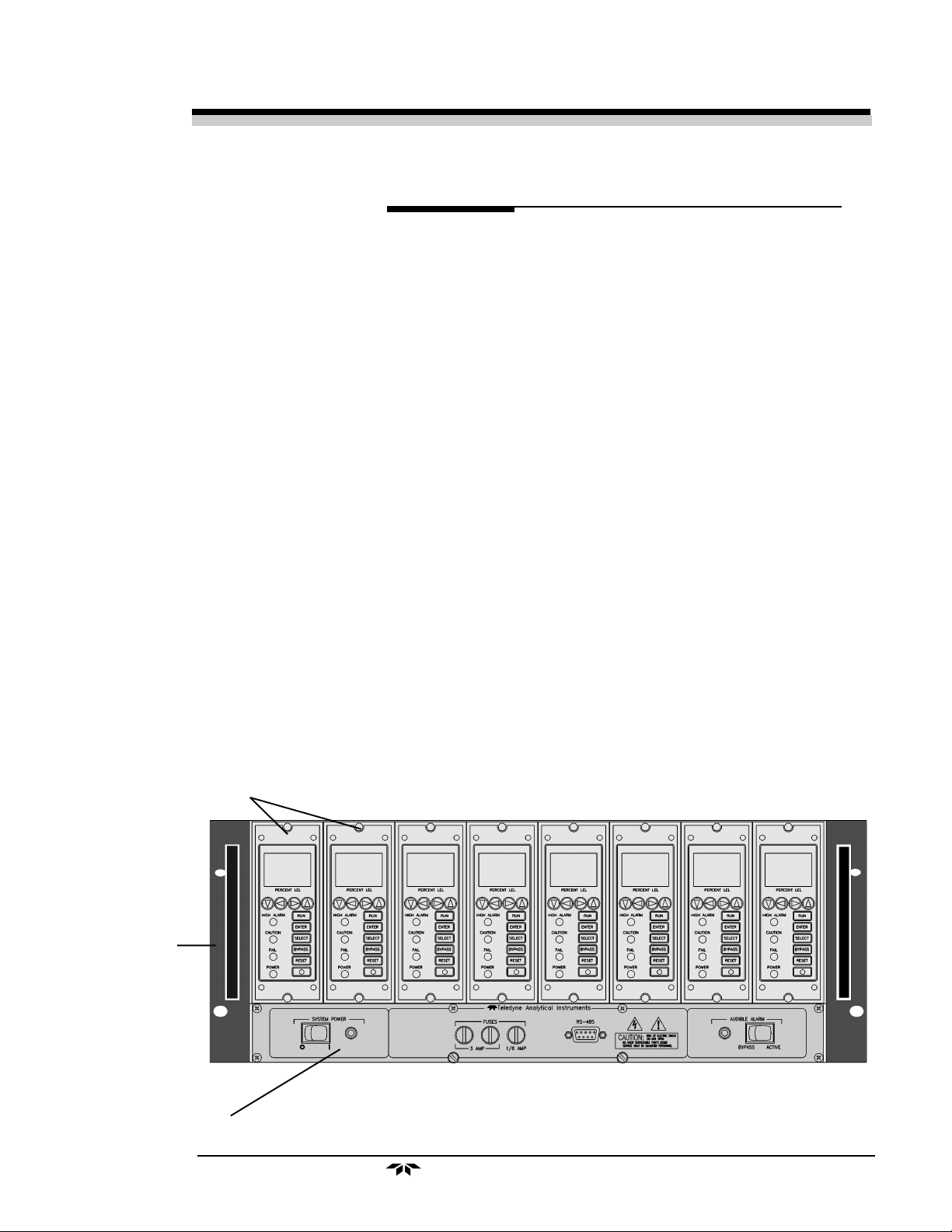
Channel Modules
System
Chassis
1.2 Description
The 1220 system is comprised of a System Chassis, Control Unit,
Channel Modules, and Remote Sensors. Each System Chassis contain one
Control Unit and up to eight Channel Modules. Each Channel Module
monitors up to two remote sensors. Since the sensors are designed for
installation in hazardous locations and are suitable for use in NEC Class I,
Division I, Groups B, C and D areas, they are (generally) located in an area
away from the 1220 System.
Control Unit
Model 1220 System
Teledyne Analytical Instruments
1-1
Page 8

1 Introduction Model 1220
1.2.1 System Chassis (19” Rack)
The System Chassis provides structural support and electrical interconnection for the Control Unit and Channel Modules (up to eight Channel
Modules may be installed). These latter plug into the sockets of the system
chassis. Terminal strips at the rear of the System Chassis provide for
external electrical connections.
1.2.2 Control Unit
The Control Unit handles power distribution to the entire system. The
main power is controlled by a switch on the front panel and the system fuses
are accessible from the front. The Control Unit also contains common
alarm relays, which indicate alarm conditions whenever any of the Channel
Modules alarm.
1.2.3 Channel Modules
Each channel module is a complete, self-contained instrument including
integral power supply, and requires only external AC power. A channel is
operational simply when plugged into the System Chassis.
Because a channel module plugs into the control module, channels can
easily be added after installation to monitor additional locations on any
control module originally supplied with less than eight channels. Channel
Modules in the same System Chassis may still be configured independently.
1.2.3.1 Main Features of the Channel Module
The main features of the Channel Module Include:
• High resolution 0-100% LEL LCD display readout
• Drop in replacement for Model 122 instruments
• 1MAN calibration capability
• Membrane switch control
• Rugged sensor design
• 2 sensors per channel option
• Microprocessor based electronics
1-2
• Two concentration alarms with adjustable set-points
• Sensor failure alarm
• User friendly touch key controls
• Passcode protection
Teledyne Analytical Instruments
Page 9
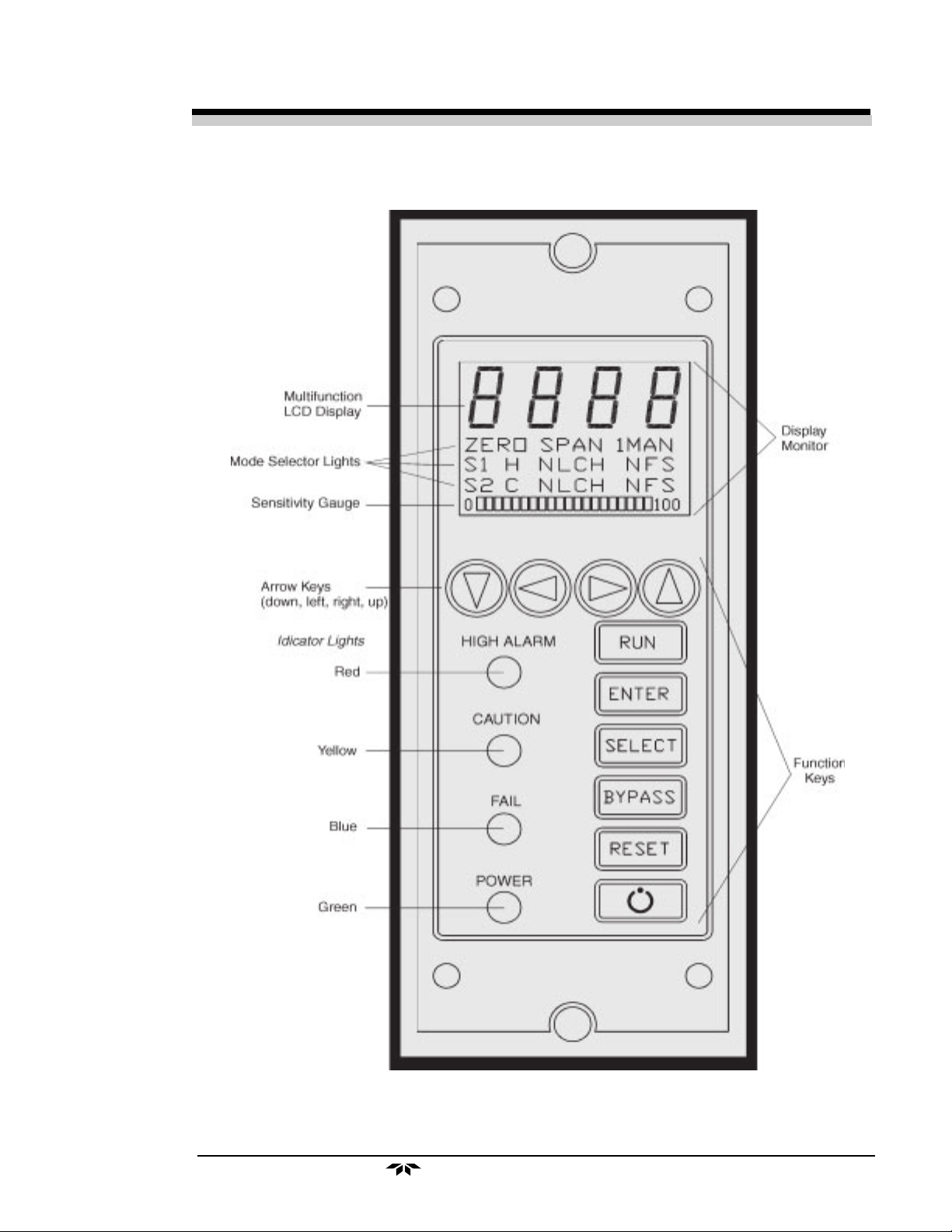
Multi-Channel Combustible Monitor Introduction 1
Model 1220 Combustible Monitor Front Panel
Teledyne Analytical Instruments
1-3
Page 10
1 Introduction Model 1220
• Failure codes and testpoints
• Two selectable analog outputs (0-10VDC or negative ground
4-20mADC)
• Extensive, automatic self-test diagnostic testing during operation
• Compact and versatile design: Small footprint with accessible
internal PCBs
1.2.4 Detector
The detector is a low temperature, catalytic oxidation, diffusion type
sensor. Each detector contains two beads: a catalytically active bead and a
thermally identical inert bead. Each bead is integrated onto a platinum
heating coil and is mounted on a stainless steel support bar. With this
rugged mounting system the detector is extremely vibration and shock
resistant. The detectors are installed near the potential source of leaks in
the region expected to be first exposed to the gas.
Combustible Gas Detector
1.2.5 Terminal Strip Housing
The terminal strip housing and probe mounts provided for this system
are junction boxes having two hubs with 3/4” pipe treads. The sensor
screws into one hub and the other hub will accommodate standard conduit.
A three-point terminal strip is installed within the housing for connection of the probe.
1-4
Teledyne Analytical Instruments
Page 11

Multi-Channel Combustible Monitor Operational Theory 2
Operational Theory
2.1 Introduction
The Model 1220 combustible gas analyzer is composed of four com-
ponents:
1. System Chassis
2. Control Unit
3. Channel Modules
4. Combustible Sensors
The System Chassis provides structural support and electrical interconnection for a Control Unit and up to eight Channel Modules. Each
Channel Module can monitor one or two sensors (dual-sensor option).
2.2 System Chassis
All electrical connections are located on the rear of the system chassis.
The nine terminal strips constitute one each for the Channel Modules and
one for the Control Module.
2.3 Control Unit
The Control Unit provides control of electrical power to the channel
module, audio alarms and external alarms through the common alarm
relays.
Alarm signals from any Channel Module trigger the corresponding
relays in the Control Unit. For example, “high” alarm signals from any
channel trigger the “high” alarm relay in the system control module. There
are three such relays in the Control Unit, one each for high, caution and
failure alarms. The failure alarm relay in the Control Unit is operated
“fail-safe”; however, the gas level alarm relays can be optionally connected
Control Unit - Front Panel
Teledyne Analytical Instruments
2-1
Page 12

2 Operational Theory Model 1220
PRIMARY
POWER
SIGNALS FROM
CHANNEL MODULES
*HIGH
*CAUTION
FAILURE
DRIVERS
POWER
SWITCH
RELAYS
AUDIBLE
ALARM BYPASS
INTERNAL
BUZZER
Control Unit - Block Diagram
for operation in the “non fail-safe” mode by setting the configuration
jumpers as indicated in the installation section 3.3.2. Each of these relays
provides SPDT contacts for operation of external devices.
POWER TO
CHANNEL
MODULES
POWER FOR
EXTERNAL
AUDIBLE
ALARMS
RELAY
CONTACT
ACTUATION
HIGH
CAUTION
FAILURE
An audible alarm is actuated when any alarm state occurs. This
audible alarm may be disconnected by switching the AUDIBLE ALARM
control switch to the BYPASSED position. When this is done, the red
lamp on the system module is illuminated as an indication that the audible
alarm is not functioning.
The Control Unit is the power entry and distribution point. The 1220
system contains universal power supplies that operate on 100-240 VAC,
50/60Hz. The power switch on the Control Unit switches power for the
entire system. The line is protected by two 3 Amp fuses, accessible from
the front panel.
A 1/8 A fuse is furnished for the electronic circuitry of the Control
Unit. The green power LED indicates that the Unit is ON.
Alarm switch S2 has two positions. Normally, the switch is set to the
ACTIVE position which provides for audible alarm when any of the
Channel Modules goes into the alarm state. When set to the BYPASS
position, the local audible alarm is turned off.
2-2
Teledyne Analytical Instruments
Page 13
Multi-Channel Combustible Monitor Operational Theory 2
2.4 Channel Module
The Model 1220 Combustible Gas Analyzer uses an Intel Microcontroller with on-board RAM and ROM to control all signal processing,
input/output, and display functions for the analyzer. The channel power is
supplied from two separate universal power supply modules (100-240
VAC), designed to be compatible with most international power sources.
The first power supply (triple outputs) supplies the voltages for logic
devices. The second power supply (dual outputs) supplies voltage for the
detector(s).
The power supply for the detector is provided with a stable current of
300mA.
Each detector is connected in a bridge circuit with the output signal
feeding an operational amplifier.
A block diagram of the functional relationships of the Channel Module is
shown in Figure 2-3.
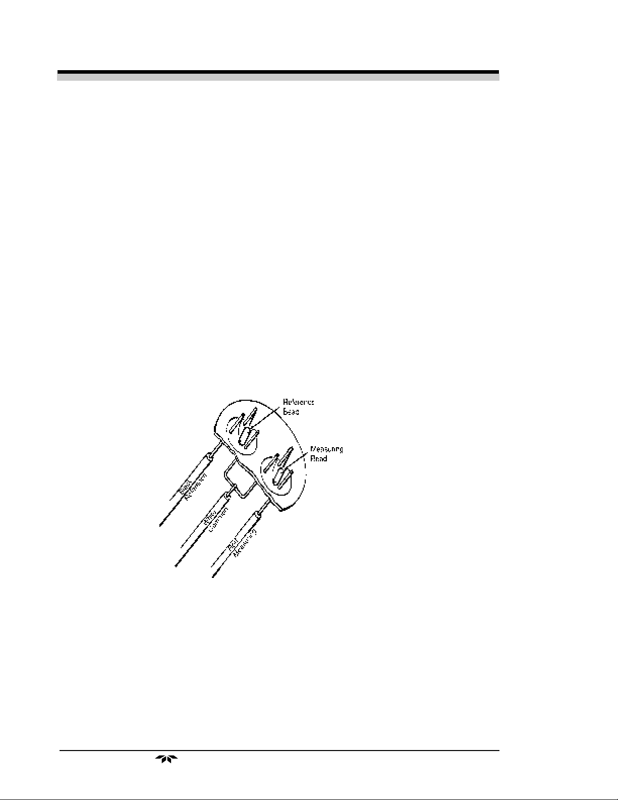
2.5 Combustible Sensors
The basic elements of the combustible gas detector are shown in
Figure 2-1. The two beads each consist of a small coil of wire coated with
an appropriate material. The measuring bead coating is a mixture of a
catalytic material with an inert binder. This catalytic material is selected to
enhance the oxidation of combustible gases. The reference bead coating is
an inert material having similar thermal properties to the other bead.
BLACK
REFERENCE
REFERENCE
BEAD
WHITE
MEASURING
BEAD
COMMON
RED
MEASURING
Figure 2-1 Combustible Gas Detector
Teledyne Analytical Instruments
2-3
Page 14

2 Operational Theory Model 1220
When exposed to a mixture containing gases and oxygen, the measuring bead coating allows the oxygen and combustibles to combine at its
surface. The energy produced by this reaction heats the measuring bead.
The rise in temperature changes the bead’s resistance and is related to the
concentration of the combustible gas. The reaction rate is dependent upon
the nature of the particular combustible gas. Raising the temperature of the
bead increases the reaction rate, which increases the sensitivity of the
sensor and reduces the observed differences of various gases. This rise in
temperature is generated by a constant-current supplied to the sensor.
The temperature of the measuring bead will be influenced by other
factors such as initial gas temperature, gas thermal conductivity, flow rates
and the temperature of its housing. The reference bead, having similar
electrical and thermal properties and being heated by the same current, but
lacking the catalytic material will be similarly affected by these extraneous
factors but not significantly affected by oxidation of the combustible gas.
These two beads are placed in close proximity to one another so that
they are affected by the same environmental factors. Thus the differences
between the changes in resistance of the two coils are directly related to the
concentration of combustible gases.
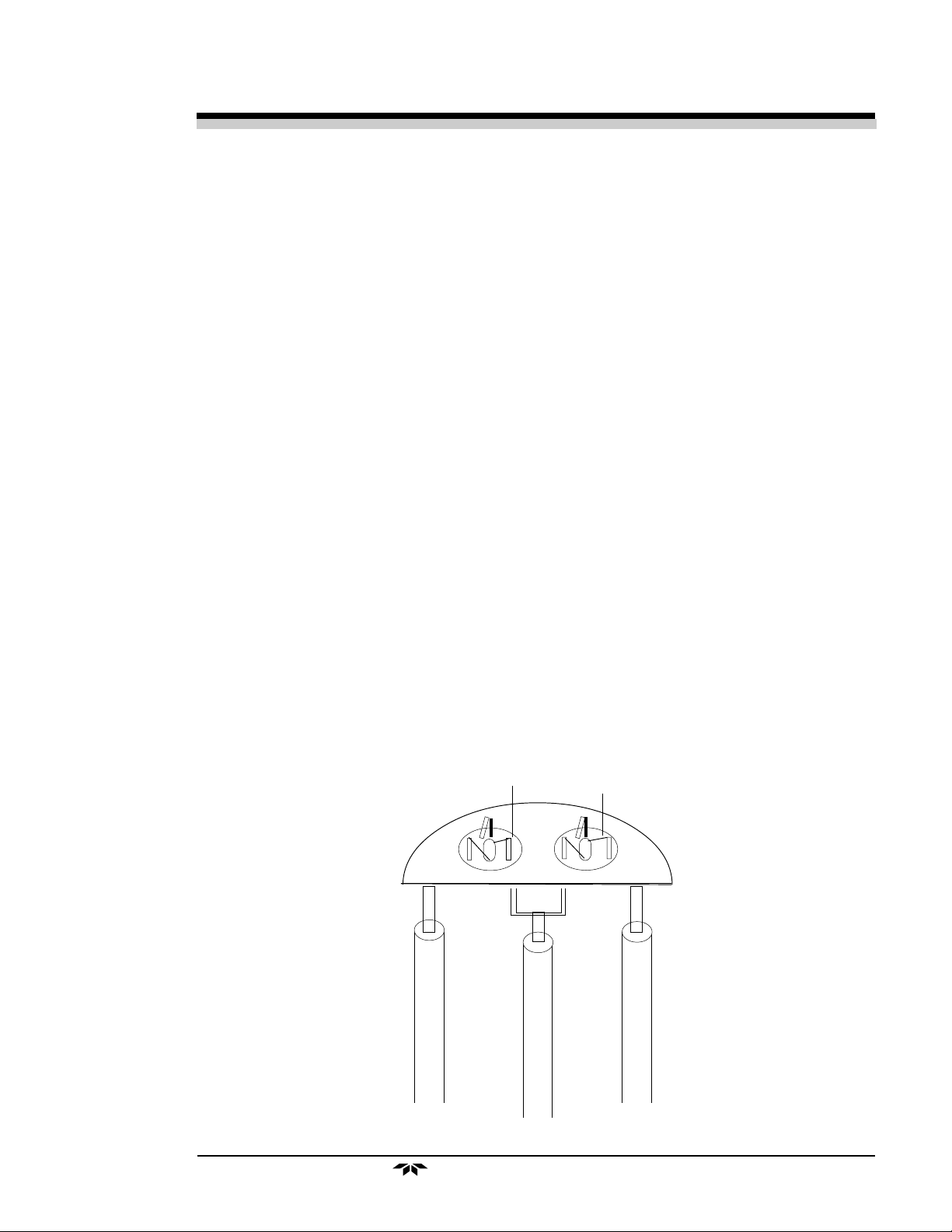
For area monitoring applications, these two beads are installed in a
metal housing as shown in Figure 2-2. Wires connected to the beads are
brought out the back of the detector through potting which provides mechanical retention of the wires and provides a gas-tight seal. A stainlesssteel flashback arrestor screen at the front of the detector covers the beads
and is held in place by a retaining cylinder pressed onto the housing. This
retaining cylinder is threaded internally to accept a flow-through adapter
for calibration.
INTERNAL THREAD FOR
CALIBRATION ADAPTER
RED
WHITE
BLACK
2-4
3/4 NPT
15/16” WRENCH FLAT
Figure 2-2 Remote Combustible Probe
Teledyne Analytical Instruments
PROBE SENSING
SURFACE
Page 15

Multi-Channel Combustible Monitor Operational Theory 2
The response of a catalytic bead detector to a number of gases is
shown in Table 1.
For lighter than air gases, the detectors are generally installed above
the source; for heavier than air gases, detectors are generally installed
below the source.
Table 1
Detector Response to Gases
COMPOUND LEL* RESPONSE FACTOR
Methane 5.0 1.00
Hydrogen 4.0 0.86
Carbon Monoxide 12.5 0.32
Ethane 3.0 1.20
Ethylene 2.7 1.26
Acetylene 2.5 1.39
Propane 2.2 1.42
Propylene 2.0 1.33
Butane 1.9 1.54
Hexane 1.1 1.50
Cyclohexane 1.3 1.44
Heptane 1.05 1.59
Benzene 1.3 1.50
Toluene 1.2 1.48
Ethylene Oxide 3.6 0.76
Methyl Ethyl Ketone 1.8 0.96
Methyl Acrylate 2.8 0.59
* Taken from Fire Hazard Properties of Flammable Liquids, Gases
and Volatile Solids, National Fire Protection Agency.
Teledyne Analytical Instruments
2-5
Page 16

2 Operational Theory Model 1220
S2
± 12 V Test
Power Supply 2
AC/DC
+ 5, ± 15 V Test
S1
M
U
X
Analog Output Test
A to D
Converter
Digital to
Analog
Converter
(DAC)
To CPU
0-10 V dc
Concentration
4-20 mA dc
Concentration
Relays
High
2-6
Keyboard
Display & LED
Indicators
Power Supply 1
AC/DC
Central
Processing
Unit
(CPU)
Figure 2-3: Block Diagram of the Signal Processing Electronics
Teledyne Analytical Instruments
Caution
Failure
RS-485
Page 17

Multi-Channel Combustible Monitor Operational Theory 2
2.5.1 Response of Combustible Sensor to Various
Gases
Response factors have been determined to relate the sensor output of a
specific compound to the output obtained using methane. A list of some
typical compounds is given in Table 1, along with their LEL (Lower
Explosive Limit) values. To determine the output of the sensor to any of
the gases listed, compared to the same concentration of methane, multiply
the reading obtained by the factor listed.
For example, if the output is calibrated with methane at 2%, the
output for ethylene at 2% would be 2.0% X 1.26 = 2.52% methane equivalent.
NOTE: The LEL and the response factors cannot be used directly for
calibration. See Table II on page 4-16 for calibration of the
instrument to gases other than Methane.
CAUTION: In most cases, the concentration of any particular
compound that the sensor is exposed to should
not exceed the LEL of that compound, or sensor
damage could occur.
The concentration of combustibles should never
exceed that which will react completely with the
available oxygen present in the sample
(stoichiometric burning), otherwise “coking” (the
deposition of carbon from incomplete combustion)
will occur at the sensor, and drift and a loss of
sensitivity will result.
CAUTION: Exposing the sensor to lead, silicone, or acidic
gases may damage the sensor.
NOTE: For compounds not listed, consult TAI.
Teledyne Analytical Instruments
2-7
Page 18

2 Operational Theory Model 1220
2-8
Teledyne Analytical Instruments
Page 19

Multi-Channel Combustible Monitor Installation 3
Installation
Installation of the analyzer includes:
1. Unpacking the system
2. Mounting the Channel Module and Control Module
3. Making the electrical connections
5. Making the gas connections
6. Testing the installation
3.1 Unpacking the Analyzer
Each TAI Model 1220 Combustible Gas Monitoring System is generally shipped with the channel modules and control module installed.
Since the system is intended as a safety monitor for detecting the
presence of combustible gases in industrial environments, the system
enclosure is normally installed in a safe area, while the remote sensors are
installed at potentially hazardous areas up to 12 thousand feet distant.
Numerous case options are available, however. One optional configuration
involves a purgeable case for installation in hazardous areas. This type of
case, which is maintained under a positive pressure, is purged with combustible-free air.
Teledyne Analytical Instruments
3-1
Page 20

3 Installation Model 1220
3.2 System Chassis
The physical dimensions and mounting hole spacing for the System
Chassis are given on Drawing D-67849. The System Chassis is designed to
fit into a standard 19" rack. It requires 7" panel height and 12.3" depth plus
allowance for cabling behind the panel.
3.2.1 Location
The System Chassis is designed for installation in a NON HAZARDOUS Environment.
3.2.2 Power
The model 1220 is designed to operate from 100/240VAC @ 50/60
Hz. Ventilation must be provided to dissipate heat generated within the
control unit. Natural convection is sufficient to cool 16 Channel Modules.
However, if more are mounted in the same chassis, forced ventilation should
be used.
3.2.3 Electrical Connections
The primary power terminals are designated H(hot), N (neutral) and
GND (ground). Connections should be made in accordance with these
designations.
All electrical connections are available at the barrier-type terminal strips
located at the rear of the control unit. These facilities are shown on the user
interconnection drawing D-67850.
WARNING: Disconnect primary power before making or
changing connections to any of the terminal
strips.
Relay contact connections are indicated as NC (normally closed), NO
(normally open) and C (common). These designations refer to the contact
state when the relay is de-energized.
Sensor connections are indicated as RD (red), WH (white) and BK
(black). These designations refer to the color of the sensor lead wires.
NOTE: The cable shield should be connected to ground only
at one end of the cable (this applies for each sensor
connection). See Figure 3.1.
3-2
Teledyne Analytical Instruments
Page 21

Multi-Channel Combustible Monitor Installation 3
Care must be observed to ensure that the sensor leads are not inadvertently connected to the signal common (C) or to the power ground while
energized. (See Figure 3-1)
Note: The maximum loop resistance for cabling to each sensor
W
is 35 , i.e. the cabling and connections should not exceed 35 total, or 35 / 2 = 17.5 on each side of the
W
W
W
sensor (See Figure 3-2).
Note that the white wire resistance is not a limiting factor
in the Loop Resistance, i.e. its resistance is not included
in the Loop Resistance measurement. To measure the
Loop Resistance directly, short the RED and BLACK
Connections at the Sensor and measure the resistance
between RED and BLACK at the channel module end of
the cable.
Figure 3-1 Sensors Connections
Teledyne Analytical Instruments
3-3
Page 22

3 Installation Model 1220
Figure 3-2 Maximum Loop Resistance for Sensor Connection
The terminals marked "Ext. Audible Alarm" provide an external signal
that is activated whenever the audible alarm is activated. By setting jumpers
on the Control Unit PCB (see section 3.3), the external signal can be either
(1) a contact closure, or (2) a powerline level signal.
Reactive loads connected to the relay contacts must be equipped with
appropriate transient suppression networks to prevent spurious triggering of
sensitive alarm circuits.
Analog output from each channel module should be connected to
monitoring equipment as shown in Figure 3-3. Note that the monitoring
equipment inputs should be floating (not grounded). The cable shield should
be connected to ground only at one end of the cable.
3-4
Figure 3-3 Analog Output Connection
Teledyne Analytical Instruments
Page 23

Multi-Channel Combustible Monitor Installation 3
3.3 Control Unit
In the event that it becomes necessary to remove the Control Unit,
primary power to the System Chassis must first be disconnected, and the six
small screws around the periphery of the Control Unit front panel removed.
The two knurled, slotted jack screws may then be backed out to pull the
Control Unit out until it is disengaged from its socket. It may then be slid out
of the chassis.
Reinstallation of the Control Unit simply requires that it be slid into the
system chassis, making certain that the circuit board lines up with the connector. The circuit may be seated in the connector by tightening the jack
screws. The six retaining screws may then be reinstalled and the primary
power reconnected to the System Chassis.
Do not hotswap (remove or install with power on) the channel modules to system chassis. Failure may occur by causing
power shorts while lining up the circuit board with the
backpanel connector.
Install channel modules starting at the end of the system
chassis, working toward the middle to prevent missalignment
problems.
3.3.1 Control Unit Fuses
The Control Unit contains three fuses. Two 3 Amp fuses protect the
entire system (one fuse for Hot, one for Neutral). An independent 1/8 Amp
fuse protects the Control Unit circuitry. To change any of the fuses, twist the
fuse holder knob counterclockwise and slide the holder out until the fuse is
visible, install the new fuse, slide the holder back in, and turn the knob
clockwise.
3.3.2 Control Unit Jumper Settings
The Control Unit may be configured by changing the installation of the
jumpers on the PCB. See the following sections for complete jumper installation information. The default jumper installation is:
Teledyne Analytical Instruments
3-5
Page 24

3 Installation Model 1220
Three alarms (CAUTION, HIGH, and FAIL) may be configured for
either fail-safe (default) or non-fail-safe operation per the following table:
The external audible alarm may be configured to operate in either the
fail-safe (default) mode or the non-fail-safe mode. It may also be configured
to provide either a contact closure (default) or the incoming line voltage to
the external connections. Additionally, the contact closure can be normally
opened or normally closed (when the relay is de-energized). The following
tables summarize the jumper settings for the external audible alarm configurations:
3-6
Teledyne Analytical Instruments
Page 25

Multi-Channel Combustible Monitor Installation 3
The internal audible alarm may be disabled by removing JP17.
WARNING: It is not recommended to remove JP17 unless
there is an external audible alarm in use. With the
jumper removed, the audible alarm will not warn
personnel about alarm conditions.
3.4 Channel Modules
Channel Modules may be removed by first unscrewing the top (retaining) screw and then unscrewing the bottom (jack) screw. As the jack screw
is backed out, it will pull the module from its socket. When the jack screw is
free, the module may be slid out by pulling on the two screws. In the event
it is desired to remove a channel module without disturbing the common
alarm circuits, the channel module may be switched into standby mode, by
pressing the switch, before removal. Reinstallation of the channel
Teledyne Analytical Instruments
3-7
Page 26

3 Installation Model 1220
module may be accomplished by sliding the module into the chassis until the
top and bottom screws can be engaged, engaging them, tightening the
bottom (jack) screw to reconnect the module, and then tightening the top
(retaining) screw.
WARNING: Disconnect power before performing any of the
following. These operations should only be performed by a qualified service technician.
3.4.1 Removing the Channel Module Cover
In order to perform the actions in the following sections 3.4.2, 3.4.3 and
3.4.4, the cover of the channel module must be removed. To remove the
cover, unscrew the two 6-32 screws that hold the cover in place, then slide
out the cover.
3.4.2 Changing the Fuse
Remove the channel module cover as in section 3.4.1. The fuse is
located as shown in the Figure 3-4
Figure 3-4 Fuse and Sensor PCB Locations
3.4.3 Adding or Removing the Second Sensor PCB
The model 1220 channel module may be configured for operation with
either one or two combustible sensors. Each sensor's power supply resides
on a sensor PCB. The location of the two sensor PCBs is shown in Figure
3-4. The single sensor PCB is factory installed at location SENSOR 1. In
order to use two sensors with a single channel module, an additional sensor
PCB must be installed at location SENSOR 2.
To add or remove the SENSOR 2 PCB, first remove the channel
module cover as in section 3.4.1 and add/remove the second sensor PCB as
shown in Figure 3-4.
3-8
Teledyne Analytical Instruments
Page 27

Multi-Channel Combustible Monitor Installation 3
3.4.4 Configuring the Internal Jumper Connections
The Channel Module outputs may be configured by setting the internal
jumpers. In addition there are several factory preset jumpers configured as
shown in the following table. Changing the internal jumpers requires removing the channel module cover as in section 3.4.1.
The Channel Module is configured to provide an RS485 communication link with the Control Unit (not available at this time). This communication link is not compatible with Control Units having the Common Meter. In
order to use the Channel Module with a Control Unit that has a Common
Meter, remove jumpers JP1 and JP3 as indicated in the following table:
Used with Model 1220
With common meter (normal)
Off
Off
Jp1
Jp3
RS485
On
On
The Channel Module can provide one of three forms of output. The
output appears at terminal 16 and 17 of the terminal strip, and is selected by
jumper setting as in the following table:
Teledyne Analytical Instruments
3-9
Page 28

3 Installation Model 1220
3.5 Combustible Sensors
The sensors should be mounted with their long axis vertical and the
sensing surface downward. It is recommended that any terminal lugs be
attached to the sensor by soldering as well as by crimping. However, care
must be observed to insure that solder does not flow onto the area where the
terminal screws must seat, as that can make it difficult to get firm, permanent
seating of the screws. If conduits carrying the sensor leads to the control unit
also carry other electrical wiring, the sensor leads must be shielded.
The Channel Modules may support one or two sensors (dual-sensor
option). When the dual-sensor option is used, the two sensors connected to a
Channel Module should monitor related areas. For example, in an area
where wind may cause leaking combustible gases to drift in different directions, the two sensors can be placed on opposite sides of the monitoring area.
Then, in the event of a leak, either of the sensors may activate the Channel
Module alarm.
3-10
Teledyne Analytical Instruments
Page 29

Multi-Channel Combustible Monitor Operation 4
Operation
4.1 Introduction
Once the System has been Installed, check all wiring to make certain
that it is correct. Check that the POWER switch on the Control Unit is in
the “OFF” position, then apply primary power to the system. Continue
start-up as follows:
1. Check that AUDIBLE ALARM switch is set to BYPASS mode
on the Control Unit.
2. Set the Control Unit POWER switch to ON. The green power
lamp and red bypass lamp should be illuminated. All the green
Power LEDs on the channel modules should be illuminated.
Each channel goes thru the process of a self-diagnostics test for
the following:
Checks the power supply 5V output
Checks the power supply +/-15V outputs
Checks the power supply +/-12V outputs
Checks the analog outputs
Checks for one sensor or two sensor mode
Checks for sensor installation
Checks that the ADC is responding
3. The Channel Modules are shipped with the ZERO and SPAN
preset, and the alarm setpoints at 50% and 80% LEL (Lower
Explosive Limits). The Channel Module relays revert to normal
state after start-up.
4. After verifying that the Control Unit, and each Channel Module
are operating normally, allow the system to stabilize over a 24
hour period.
Teledyne Analytical Instruments
4-1
Page 30

4 Operation Model 1220
4.2 Control Unit Operation
4.2.1 System Power Switch and LED
The power to the entire 1220 system is controlled by the System
Power Switch.
The green System Power LED indicates system power status (ON/
OFF).
4.2.2 Audible Alarm Switch and Bypass LED
The Audible Alarm Switch overrides the audible alarm when in the
Bypass position. The red Bypass LED lights when the audible alarm is
bypassed.
4.2.3 Fuses
For fuse replacement/installation, see section 3.3.1 and 3.4.3
4.2.4 RS485 Port
NOTE: This feature is not presently supported--contact the factory for
application assistance.
An RS485 port is provided at the 9-pin D-sub connector. The RS485
port is connected internally to all of the Channel Modules in the system.
4-2
Control Unit - Front View
Teledyne Analytical Instruments
Page 31

Multi-Channel Combustible Monitor Operation 4
Channel Module Front Panel Controls and Indicators
Teledyne Analytical Instruments
4-3
Page 32

4 Operation Model 1220
4.3 Channel Module Front Panel
Controls and Indicators
STANDBY Switch - When pressed, this membrane switch
places the Channel Module in the standby mode, i.e.,
removes power from the sensor(s) and extinguishes the
LCD display.
NOTE: If the relays are configured for fail-safe operation, they will remain
energized. If an alarm condition exists, the Channel Module will
return to a non-alarm state.
RESET Switch - After an alarm condition is no longer
RESET
present, as indicated by the concentration value shown on
the display, press this membrane switch to return the relay
or relays to the non-alarm (normal) state.
BYPASS Switch - When in an alarm condition, pressing
BYPASS
NOTE: The red, yellow and blue alarm LEDs begin to flash. They remain
flashing until the alarms are reset or the BYPASS switch is pressed
again.
SELECT
this membrane switch disables the Control Unit audible
alarm.
SELECT Switch - Use this membrane switch to access any
of the Channel Module’s four user-configurable modes and
their options. The four modes are:
1. Sensor and Calibration Mode - This mode allows you to
select sensor 1 (S1) or sensor 2 (S2) and then set the
ZERO and SPAN values. It also is used during the
“One-Man” (1MAN) calibration option.
2. Alarm Configuration Mode - This mode allows you to
adjust the set points of the High and/or Caution alarms
as well as define the configuration for the alarms as
“Fail-Safe” / “Non-Fail-safe” and/or “Latching” / “NonLatching”.
3. Identification (ID) Code Set Mode - This mode allows
you to define the unique ID for each Channel Module
for use with RS-485 communication (Special option,
contact factory).
4. Passcode Enable/Disable Mode - This mode allows you
to enable or disable the factory-defined passcode.
4-4
Teledyne Analytical Instruments
Page 33

Multi-Channel Combustible Monitor Operation 4
ENTER Switch - Use this membrane switch in
ENTER
RUN
conjunction with the SELECT Switch to select a
user-configurable mode and then the option highlighted.
RUN Switch - Pressing this membrane switch places
the Channel Module in the analysis mode, i.e., the
unit is operational.
When in one of the four
user-configurable modes, all
arrows allow you to navigate
through the options. In
addition, the Up/Down
arrow keys can be used to set
the values shown on the
display for ZERO and SPAN
and also increase/decrease
the value of the HIGH and
CAUTION alarms.
HIGH ALARM
HIGH ALARM
CAUTION
CAUTION
FAIL
FAIL
POWER
Red LED indicates High alarm condition. Flashes
when bypassed.
Yellow LED indicates Caution alarm condition.
Flashes when bypassed.
Blue LED indicates a Channel Module or Sensor
failure. Flashes when bypassed.
Green LED remains on during operation, turns off
in STANDBY Mode.
Teledyne Analytical Instruments
4-5
Page 34

4 Operation Model 1220
NOTE:
When one of these modes
are selected, the field light
flashes indicating which
mode the monitor is on.
Configuration Display Panel Fields
“S1” highlighted indicates that Sensor 1 options may be set.
“S2” highlighted indicates that Sensor 2 options may be set.
This option is used to zero (“0”) calibrate the Channel Module.
This option is used to span calibrate the Channel Module.
This option enables a single person to perform both a span and
zero calibration.
“H” highlighted indicates that the High Alarm value can be set
by using the Up/Down Arrow Keys.
“C” highlighted indicates that the Caution Alarm value can be
set by using the Up/Down Arrow Keys.
When the instrument goes into an alarm condition, the alarm
relay switches. If “LCH” (latched) was selected, the alarm relay
remains switched (latched) even after the alarm condition has
been cleared. Using this configuration, you must press the
RESET switch to unlatch (unlock) the relay.
When the instrument goes into an alarm condition, the alarm
relay switches. If “NLCH” (non-latched) was selected, the
alarm relay switches (unlatches) when the alarm condition is
cleared.
4-6
Teledyne Analytical Instruments
Page 35

Multi-Channel Combustible Monitor Operation 4
If “FS” is selected, the associated relay is in the Fail-safe Mode,
i.e., the relay is “normally energized”.
If “NFS” is selected, the associated relay is in the Non-Fail-safe
Mode, i.e., the relay is “normally de-energized”.
Sensitivity Gauge
The Sensitivity Gauge monitors the life of the sensor. It does so
by monitoring successive span procedures throughout the life of
the sensor. As the sensor gets older it’s resistance builds,
lessening the sensitivity.
LCD Display
The LCD Display shows the LEL in monitor (RUN) mode,
alarm settings during the configuration mode, and calibration
values during Span and Zero operations.
4.4 Calibration Procedures
4.4.1 Zero Calibrating a Single Sensor Channel Module
NOTE:
To accomplish the following task, two operators are needed.
Operator one at the Control Unit and operator two at the
probe. Both operators are involved in the calibration process.
They must be in constant communication, by phone or other
means.
(A) = Operator One at the Control Unit
(B) = Operator Two at the probe
1. (A) At the Front Panel of the Channel Module to be calibrated:
a. Press SELECT.
b. Use the right or left arrow key to highlight the ZERO option.
c. Press ENTER.
Result: Alarms are deactivated and the ZERO display
option flashes.
2. (B) Introduce zero gas into the sensor.
3. (A) After the reading has stabilized:
Teledyne Analytical Instruments
4-7
Page 36

4 Operation Model 1220
a. Press the up or down arrow key until the display reads “0”.
b. Press ENTER.
4. (B) Disconnect the zero gas from the sensor.
5. (A) If necessary, proceed to the previous or next procedure. Other-
wise, press RUN to place the instrument in the analysis mode.
4.4.2 Span Calibrating a Single Sensor Channel Module
NOTE:
To accomplish the following task, two operators are needed.
Operator one at the Control Unit and operator two at the
probe. Both operators are involved in the calibration process.
They must be in constant communication, by phone or other
means.
(A) = Operator One at the Control Unit
(B) = Operator Two at the probe
1. (A) At the Front Panel of the Channel Module to be calibrated:
a. Press SELECT.
b. Use the right or left arrow key to highlight the SPAN option.
c. Press ENTER.
Result: Alarms are deactivated and the SPAN display
option flashes.
2. (B) Introduce span gas into sensor.
3. (A) After the reading stabilizes:
a. Press the up or down arrow key until the display reads the value
that corresponds to the LEL of the certified span gas used.
NOTE: Information about calibration valves for various com-
bustible gases appears in Table 1 on page 2-5 and in Section
4.11 on page 4-14
4-8
NOTE:
If you need to adjust the Sensitivity Gauge, see Paragraph 4.8
for recommendations.
b. Press ENTER.
4. (B) Disconnect the span gas from the sensor.
5. (A) If necessary, proceed to the previous or next procedure. Other-
wise, press RUN to place the instrument in the analyze mode.
Teledyne Analytical Instruments
Page 37

Multi-Channel Combustible Monitor Operation 4
4.4.3 Zero Calibrating a Dual Sensor Channel Module
NOTE:
To accomplish the following task, two operators are needed.
Operator one at the Control Unit and operator two at the
probe. Both operators are involved in the calibration process.
They must be in constant communication, by phone or other
means.
(A) = Operator One at the Control Unit
(B) = Operator Two at the probe
1. (A) At the Front Panel of the Channel Module to be calibrated:
a. Press SELECT.
b. Use the up or down arrow key to highlight the appropriate
sensor to be calibrated (S1 = Sensor 1 or S2 = Sensor 2).
c. Press ENTER.
d. Perform the procedure listed in Paragraph 4.4.1 beginning with
Step “1b” and then return here.
2. To calibrate the second sensor, perform this procedure again beginning with Step “1b”.
4.4.4 Span Calibrating a Dual Sensor Channel Module
NOTE:
To accomplish the following task, two operators are needed.
Operator one at the Control Unit and operator two at the
probe. Both operators are involved in the calibration process.
They must be in constant communication, by phone or other
means.
(A) = Operator One at the Control Unit
(B) = Operator Two at the probe
1. (A) At the Front Panel of the Channel Module to be calibrated:
a. Press SELECT.
b. Use the up or down arrow key to highlight the appropriate
sensor to be calibrated (S1 = Sensor 1 or S2 = Sensor 2).
c. Press ENTER.
d. Perform the procedure listed in Paragraph 4.4.2 beginning with
Step “1b” and then return here.
2. To calibrate the second sensor, perform this procedure again beginning with Step “1b”.
Teledyne Analytical Instruments
4-9
Page 38

4 Operation Model 1220
4.4.5 Using the “1MAN” Calibration Option
The two following calibration procedure can be performed by one
technician.
4.4.5.1 Zero and Span Calibrating a Single Sensor
Channel Module
1. At the Front Panel of the Channel Module to be calibrated:
a. Press SELECT.
b. Use the right or left arrow key to highlight the 1MAN option.
c. Press ENTER.
2. At the remote probe site, introduce certified span gas to the sensor.
3. Wait 60 seconds so that the reading can stabilize.
4. Remove the span gas and introduce zero gas to the sensor.
5. Wait 60 seconds so that the reading can stabilize.
6. At the Front Panel of the Channel Module being calibrated:
a. Press the up or down arrow key until the display reads “0”.
b. Press ENTER.
c. Press the up or down arrow key until the display reads the value
that corresponds to the value of the certified span gas used.
NOTE: Information about calibration values for various combustible
gases appears in Table 1 on page 2-5 and in Section 4.11 on page
4-14
NOTE:
If you need to adjust the Sensitivity Gauge, see Paragraph 4.8
for recommendations.
d. Press ENTER.
7. If necessary, proceed to the previous or next procedure. Otherwise,
press RUN to place the instrument in the analysis mode.
4.4.5.2 Zero and Span Calibrating a Dual Sensor Channel
Module
1. At the Front Panel of the Channel Module to be calibrated:
a. Press SELECT.
b. Use the up or down arrow key to highlight the appropriate
sensor to be calibrated (S1 = Sensor 1 or S2 = Sensor 2).
c. Press ENTER.
d. Use the right or left arrow key to highlight the 1MAN option.
e. Press ENTER.
f. Perform the procedure listed in Paragraph 4.4.5.1 beginning
with Step “2” and then return here.
4-10
Teledyne Analytical Instruments
Page 39

Multi-Channel Combustible Monitor Operation 4
2. To calibrate the second sensor, perform this procedure again beginning with Step “1b”.
4.5 Alarm Configuration Procedures
4.5.1 Defining the Setpoint for the High or Caution Alarm
NOTE:
(Applies to Dual Sensor Instruments Only)
Caution Alarm relays are shared by both sensors, i.e., only
one setpoint for the High Alarm and one setpoint for the
Caution Alarm can be defined.
The High and
1. At the Front Panel of the Channel Module to be configured:
a. Press SELECT twice to enter the “Alarm Configuration”
Mode. (“H” {High} will be flashing.)
b. Use the up or down arrow key to highlight the appropriate alarm
to be defined (“H” = High Alarm or “C” = Caution Alarm).
c. Press ENTER to select the alarm.
d. Use the up or down arrow key to adjust the displayed value to
the desired percentage for the alarm selected.
e. Press ENTER.
2. If necessary, proceed to the previous or next procedure. Otherwise,
press RUN to place the instrument in the analysis mode.
4.5.2 Configuring Alarm Relay Settings
4.5.2.1 Setting the Fail-safe or Non-Fail-safe Mode
1. At the Front Panel of the Channel Module to be configured:
a. Press SELECT twice to enter the “Alarm Configuration”
Mode. (“H” {High} will be flashing.)
b. Use the up or down arrow key to highlight the appropriate alarm
to be defined (“H” = High Alarm or “C” = Caution Alarm).
c. Use the left or right arrow key to highlight the “FS” option.
d. Press ENTER.
e. Use the up or down arrow key to switch to the desired configu-
ration for the alarm (“FS” = Fail-safe and “NFS” = Non-Fail-
safe.)
f. Press ENTER.
2. If necessary, proceed to the previous or next procedure. Otherwise,
press RUN to place the instrument in the analysis mode.
Teledyne Analytical Instruments
4-11
Page 40

4 Operation Model 1220
4.5.2.2 Setting the Latching or Non-Latching Mode
1. At the Front Panel of the Channel Module to be configured:
a. Press SELECT twice to enter the “Alarm Configuration”
Mode. (“H” {High} will be flashing.)
b. Use the up or down arrow key to highlight the appropriate alarm
to be defined (“H” = High Alarm or “C” = Caution Alarm).
c. Use the left or right arrow key to highlight the “LCH” option.
d. Press ENTER.
e. Use the up or down arrow key to switch to the desired configu-
ration for the alarm (“LCH” = Latching and “NLCH” = Non-
Latching.)
f. Press ENTER.
2. If necessary, proceed to the previous or next procedure. Otherwise,
press RUN to place the instrument in the analysis mode.
4.6 Setting the ID Code
1. At the Front Panel of the Channel Module to be configured:
a. Press SELECT three times to enter the “ID Code” Mode. (The
current ID code will be displayed.)
b. Press ENTER.
c. Use the left and right arrow key to select the digit to be modi-
fied and the up and down arrow keys to modify the selected
digit.
d. Repeat Step “c” to modify the remaining digits.
e. Press ENTER to save the ID Code.
2. If necessary, proceed to the previous or next procedure. Otherwise,
press RUN to place the instrument in the analysis mode.
4.7 Enabling/Disabling the Pass Code
1. At the Front Panel of the Channel Module to be configured:
a. Press SELECT four times to enter the “Pass Code” Mode.
(The current pass code state {“Poff” = Passcode off or “P on”
= Passcode on} will be displayed.)
b. Press ENTER.
c. Use the up or down arrow key to modify the state of the code.
d. Press ENTER to accept the change.
4-12
Teledyne Analytical Instruments
Page 41

Multi-Channel Combustible Monitor Operation 4
2. If necessary, proceed to the previous or next procedure. Otherwise,
press RUN to place the instrument in the analysis mode.
Passcode: Press the Down arrow key followed by the Right arrow key.
4.8 Setting the Sensitivity Gauge
NOTE: The sensitivity gauge can only be adjusted when performing a
local (Paragraph 4.3) or “1MAN” (Paragraph 4.4.5.1) span
calibration.
Recommendations:
1. Upon initial installation of a new sensor, use the left or right arrow
key to set the gauge to read “100”.
2. Each time that you complete a span calibration procedure, the value
of the sensitivity gauge will be updated to indicate the sensor’s
sensitivity (measured relative to its original sensitivity). This can
be used as an estimate of the sensor’s remaining life.
4.9 Routine Operation
During routine operation, the system will require no attention unless
an alarm state occurs. In the event of an alarm indication, the audible
alarm may be silenced in one of two ways:
1. Move the AUDIBLE ALARM switch on the system control module to BYPASS. This will immediately silence the audible
alarm and also prevent an audible indication from occurring should
another channel go into an alarm state.
2. Press the BYPASS button on the Channel Module. The associated
alarm LED will flash and the AUDIBLE ALARM will be silenced
until the ALARM condition is cleared. In this case, only the
specific alarm channel will be affected. In the occurrence of an
additional alarm in the same channel, or any alarm in any other
channel, the AUDIBLE ALARM will again activate.
In either case, once the audible alarm has been silenced the combustible gas level may be determined by viewing the LCD display reading on
the channel module. When the level has diminished to less than the alarm
level, the system may be reset by depressing the RESET button.
Teledyne Analytical Instruments
4-13
Page 42

4 Operation Model 1220
4.10 FAIL Alarm Conditions
The possible FAIL Alarm Conditions are:
- A sensor fails.
- One of the power suppliers fails.
- 0-10V Output fails.
- The ADC times out without a proper end-of-conversion (EOC).
Whenever a failure is detected, the FAIL alarm is activated: the blue
LED turns on, the alarm relay is de-energized (the FAIL relay is FAILSAFE, and the audible alarm is activated. The power supplies to both
sensors are disabled.
Failure alarms are accompanied with a FAIL code number. The
display alternates between “FAIL” and the code number.
The failure alarm may be bypassed (by pressing the Bypass Button),
in which case, the blue LED flashes, and the audible alarm is deactivated.
To acknowledge a failure condition, press RESET. This restarts the
instrument (as if the button has been pressed twice). Alternatively, you
may turn the unit OFF using the button.
NOTE: The reason the failure modes require restarting the instru-
ment is that once a failure has been detected, the unit should
not be used until the error is fixed.
When a failure alarm is detected, the other two alarms (caution and
high) are disabled.
4.11 Calibration of Combustible Gas Detectors to the
LEL of Gases other than Methane
The lower explosive limit (LEL) varies substantially between the
different explosive gases. It is, therefore, necessary to consider the LEL of
a particular gas as well as the relative response of a detector to this gas in
order to calibrate the detector to indicate the concentration as a percentage
of the LEL. The most commonly used calibration gas contains small
4-14
Teledyne Analytical Instruments
Page 43

Multi-Channel Combustible Monitor Operation 4
amounts (percentages) of methane mixed with air. Table II lists calibration
factors for the TAI Combustible gas sensor which can be used to calibrate
these detectors to indicate the percent LEL of the specific gases. These
calibration factors are based on the use of methane in the air as the calibration gas and take into account both relative response and LEL of the
specific gases.
To use these calibration factors, multiply the percent volumeric
concentration of methane in the calibration gas by the appropriate calibration factor. The number thus obtained is the meter reading to which the
instrument should be spanned, in accordance with the calibration procedures, when the sensor is exposed to the calibration gas. When so adjusted, the instrument will be calibrated to indicate the percent LEL of the
selected gas.
Use the following formula to determine the value to enter during the
span calibration procedure:
V = CH4 x CF
Where:
V = Value to enter during span calibration
CH4 = Percent methane in air
CF = Calibration Factor from Table II
EXAMPLE:
CH4 = Certified Calibration Gas = 2.2% methane in air
Gas for which calibration is desired = Ethane
CF = Calibration Factor from Table II = 28
V = Calibration Meter Reading = 62 = 2.2 X 28
Using the calibration procedures in this manual, adjust the span so
that with calibration gas flowing through the calibration adapter, a meter
reading of 62 is obtained. The instrument will then be calibrated to indicate 0 to 100% LEL of Ethane.
Teledyne Analytical Instruments
4-15
Page 44

4 Operation Model 1220
TABLE II
Calibration Factors for TAI Combustible Gas Sensor
COMPOUND CALIBRATION FACTOR
Methane 20
Hydrogen 29
Carbon Monoxide 25
Ethane 28
Ethylene 29
Acetylene 29
Propane 32
Propylene 38
Butane 34
Cyclohexane 53
Heptane 60
Pentane 46
Toluene 56
Ethylene Oxide 37
Methyl Ethyl Ketone 58
Methyl Acrylate 61
Hexane 61
4-16
Teledyne Analytical Instruments
Page 45

Multi-Channel Combustible Monitor Failure and Error Codes 5
Failure and Error Codes
5.1 Failure Codes
Teledyne Analytical Instruments
5-1
Page 46

5 Failure and Error Codes Model 1220
5.2 Error Codes
5-2
Teledyne Analytical Instruments
Page 47

Multi-Channel Combustible Monitor Appendix
Appendix
A-1 Specification
Range: 0-100% LEL Combustible Gas in Air
(Methane equivalent)
Number of Channels: Up to eight channels
Repeatability: 2 % of full scale
Accuracy: ±2% of full scale at constant tempera-
ture
Response Time: 90% in less than 15 seconds
Operating Temperature: 0 to 50oC
Temperature Stability: ±1% over 10oF
Alarms: Two Adjustable Alarm Point plus
Failure Alarm Indicators illuminate at
Alarm Setpoint. HIGH-RED;
CAUTION-AMBER; FAIL-BLUE.
Sensor Type: Two element catalytic bead, anodized
aluminum housing, Stainless Steel
(Flame Arrestors)
Signal Output: Internal: LCD Display
External: 0-10 VDC or 4-20 mA
negative ground (user-configurable)
Teledyne Analytical Instruments
A-1
Page 48

Appendix Model 1220
Power Requirements: 100-240 VAC 50/60 Hz
System Enclosure: Control Module fits standard 19”
Relay Rack
Dimensions: 7” H x 12.3” D x 19” W
Maximum Loop Resistance for
Sensor Connections/Cabling: 35
W
Maximum Loop Resistance
for 4-20 mA OUTPUT: 600
W
Sensor Probe Mounting: 2 MTG. Holes , 3/16” Diameter, 2 3/
8”
C-TO-C (custom probes for special
applications).
Field Connections: Barrier-Type Terminal Strips with
screw connections.
Alarm Output: Form “C” Relay Contacts (SPDT)
Recommended Spare Parts List
Qty Part Number Description
2 A-12698 Adapter, Flow-Thru
10 A-11091 Adapter, Female
4 B-12093 Detector
5 F-1374 Fuse, Type 3AG, 1/8A
10 F-229 Fuse, Micro, 2A
5 F-1379 Fuse, Type 3AG, 3A
1 C-65446 PCB, Front Panel Display
1 C-67479 PCB, Constant Current Supply
1 C-65446 PCB, Front Panel
1 C-66910 Front Panel With Membrane
_____________________
A minimum charge is applicable to spare parts orders.
Note: Orders for replacement parts should include the part number (if
available) and the model and serial number of the instrument for
which the parts are intended.
A-2
Teledyne Analytical Instruments
Page 49

Multi-Channel Combustible Monitor Appendix
Orders should be sent to:
TELEDYNE Analytical Instruments
16830 Chestnut Street
City of Industry, CA 91749-1580
Phone (626) 934-1500, Fax (626) 961-2538
TWX (910) 584-1887 TDYANYL COID
Web: www.teledyne-ai.com
or your local representative.
Drawing List
C-67019 Outline Drawing, Control Unit
A-13450 Outline Drawing, Sensing Detector
B-68172 Interconnection Diagram, Model 1220
C-67478 Schematic Diagram, Constant current supply
D-65445 Schematic Diagram, Model 1220 Front Panel Display
D-65442 Schematic Diagram, Model 1220 Main PCB
Teledyne Analytical Instruments
A-3
Page 50

Appendix Model 1220
A-4
Teledyne Analytical Instruments
 Loading...