

Page 1
Getting Started
Manual
LabMaster 10 Zi Series
Oscilloscopes
Page 2

Page 3

LabMaster 10 Zi Series Oscilloscopes
Getting Started Manual
May, 2013
Page 4

LabMaster 10 Zi Series Oscilloscope Getting Started Manual
© 2013 Teledyne LeCroy. All rights reserved.
Unauthorized duplication of Teledyne LeCroy documentation materials
other than for internal sales and distribution purposes is strictly prohibited.
However, clients are encouraged to distribute and duplicate Teledyne
LeCroy documentation for their own internal educational purposes.
Teledyne LeCroy and other product or brand names are trademarks or
requested trademarks of their respective holders. Information in this
publication supersedes all earlier versions. Specifications are subject to
change without notice.
922561-00 Rev A
May 2013
Page 5

Getting Started Manual
922561-00 Rev A
i
Contents
Welcome ......................................................................................................... 1
Safety Instructions........................................................................................... 2
Symbols ............................................................................................................ 2
Precautions ...................................................................................................... 2
Operating Environment ................................................................................... 3
Cooling ............................................................................................................. 3
Cleaning ........................................................................................................... 4
Lifting and Moving ........................................................................................... 4
Calibration ........................................................................................................ 4
Power ............................................................................................................... 5
LabMaster 10 Zi Overview ............................................................................... 7
Front of MCM-Zi Master Control Module ........................................................ 9
Back of MCM-Zi Master Control Module ....................................................... 10
Front of 10-xxZi Acquisition Module .............................................................. 11
Back of 10-xxZi Acquisition Module ............................................................... 12
Front of ChannelSync Mainframe Hub........................................................... 13
Back of ChannelSync Mainframe Hub ............................................................ 13
Input/Output Panel ........................................................................................ 14
Standard High Bandwidth Accessories .......................................................... 15
LabMaster Setup ........................................................................................... 16
PCIe 1 Lane Cable SYNC Connection(s) .......................................................... 16
PCIe 4 Lane DATALINK Connection(s) ............................................................ 18
SMA 72" Cables - ChannelSync Clock ............................................................. 21
ChannelSync Mainframe Hub ........................................................................ 23
Power Cable and Main Power Switch ............................................................ 24
Touch Screen and External Displays .............................................................. 25
Removing and Attaching the Front Panel ...................................................... 28
Signal Inputs .................................................................................................. 30
Probes ............................................................................................................ 30
Interfaces ....................................................................................................... 30
Probe Dialog ................................................................................................... 35
Page 6

LabMaster 10 Zi Oscilloscopes
ii
922561-00 Rev A
Basic Controls ................................................................................................ 37
Front Panel Control Groups ........................................................................... 37
Display Dashboard ......................................................................................... 42
Turning On Traces .......................................................................................... 55
Timebase ....................................................................................................... 56
Timebase Dialog ............................................................................................. 56
Combining Channels ...................................................................................... 56
Sampling Modes ............................................................................................. 58
Vertical .......................................................................................................... 67
Channel Dialog ............................................................................................... 67
LabMaster Channel Setup .............................................................................. 71
LabMaster Deskew Calibration ...................................................................... 72
Trigger ........................................................................................................... 79
Trigger Overview ............................................................................................ 79
Trigger Types .................................................................................................. 80
Trigger Settings .............................................................................................. 83
Trigger Setup .................................................................................................. 84
TriggerScan ..................................................................................................... 90
Viewing Waveforms ...................................................................................... 94
Display ............................................................................................................ 94
Persistence ..................................................................................................... 97
WaveStream Display Mode ............................................................................ 99
Adjusting Trace Intensity ............................................................................... 99
Zooming Waveforms ................................................................................... 100
Zooming a Single Channel ............................................................................ 101
Touch-and-Drag Zooming ............................................................................ 102
Quick Zoom .................................................................................................. 103
Turning Off Zoom ......................................................................................... 103
Cursors ........................................................................................................ 104
Quickly Displaying Cursors ........................................................................... 104
Cursor Setup ................................................................................................. 105
Cursors on Math Functions .......................................................................... 106
Page 7

Getting Started Manual
922561-00 Rev A
iii
Measurements ............................................................................................ 107
Turning On Measurements .......................................................................... 107
Quick Access to Parameter Setup Dialogs ................................................... 107
Parameter Setup .......................................................................................... 108
Measure Modes ........................................................................................... 109
Help Markers................................................................................................ 110
Math ........................................................................................................... 112
Math Setup .................................................................................................. 112
Analysis ....................................................................................................... 114
Track vs. Trend ............................................................................................. 115
Viewing Histograms ..................................................................................... 116
Viewing Trends ............................................................................................ 119
Viewing a Track ............................................................................................ 120
Pass/Fail Testing ........................................................................................... 121
Mask Testing ................................................................................................ 128
WaveScan Overview .................................................................................... 131
Customization Overview .............................................................................. 133
Documenting Work with LabNotebook ....................................................... 134
LabNotebook Overview ............................................................................... 134
Using LabNotebook ...................................................................................... 135
Save/Recall.................................................................................................. 139
Save/Recall Overview .................................................................................. 139
Saving and Recalling Setups ......................................................................... 140
Saving and Recalling Waveforms ................................................................. 142
Utilities ........................................................................................................ 146
Utilities Dialog .............................................................................................. 146
Status ........................................................................................................... 147
Software Options ......................................................................................... 147
Remote Control ............................................................................................ 147
Print (Hardcopy) Functions .......................................................................... 150
Aux Output ................................................................................................... 155
Date/Time .................................................................................................... 157
Disk Utilities ................................................................................................. 158
Page 8

LabMaster 10 Zi Oscilloscopes
iv
922561-00 Rev A
Preferences Setup ........................................................................................ 159
Preferences Dialog ....................................................................................... 159
Acquisition ................................................................................................... 160
E-Mail ........................................................................................................... 162
Color ............................................................................................................. 163
Miscellaneous .............................................................................................. 164
System Recovery ......................................................................................... 165
Reference .................................................................................................... 166
Warranty ...................................................................................................... 166
Specifications ............................................................................................... 167
Certifications ................................................................................................ 167
Contact Teledyne LeCroy ............................................................................. 171
End-User License Agreement for Teledyne LeCroy® X-Stream Software ..... 172
Windows® License Agreement ..................................................................... 191
Index ........................................................................................................... 192
Page 9

Getting Started Manual
922561-00 Rev A
1
Welcome
Thank you for purchasing a Teledyne LeCroy product. We're certain you'll be
pleased with the detailed features so unique to our instruments.
About this Manual
This manual contains information needed to set up and operate the
oscilloscope including Hardware Overview and Set Up, Probe and Signal
Connection Interfaces, Basic Controls, Core Oscilloscope Functions, and
Reference (certifications and contact information).
The Teledyne LeCroy website at teledynelecroy.com always maintains the
most current specification information. The website should be checked for
frequent updates.
Support
When your product is delivered, verify that all items on the packing list or
invoice copy have been shipped to you. Contact your nearest Teledyne
LeCroy customer service center at the address listed in this manual or your
national distributor if anything is missing or damaged. If you do not contact
us immediately, we cannot be responsible for replacement.
Thank You
We truly hope these materials increase your enjoyment and understanding
of your Teledyne LeCroy product.
Sincerely,
David C. Graef
Vice President and Chief Technology Officer
Teledyne LeCroy
Page 10
LabMaster 10 Zi Oscilloscopes
2
922561-00 Rev A
CAUTION of damage to instrument, or WARNING of hazard to
health. Attend to the accompanying information to protect
against personal injury or damage. Do not proceed until
conditions are fully understood and met.
HIGH VOLTAGE. Risk of electric shock or burn.
Measurement ground connection.
Safety (protective) ground connection.
Alternating Current.
Standby Power (front of MCM-Zi).
Safety Instructions
Observe generally accepted safety procedures in addition to the precautions
specified here to keep the instrument operating in a correct and safe
condition. The overall safety of any system incorporating this instrument is
the responsibility of the assembler of the system.
Symbols
These symbols appear on the instrument's front or rear panels and in
documentation to alert you to important safety considerations.
Precautions
Use proper power cord. Use only the power cord shipped with this
instrument and certified for the country of use.
Maintain ground. This product is grounded through the power cord
grounding conductor. To avoid electric shock, connect only to a grounded
mating outlet.
Connect and disconnect properly. Do not connect/disconnect probes or
test leads while they are connected to a voltage source.
Page 11

Getting Started Manual
922561-00 Rev A
3
Observe all terminal ratings. Do not apply a voltage to any input (C1, C2, C3,
C4 or EXT) that exceeds the maximum rating of that input. Refer to the front
of the oscilloscope for maximum input ratings.
Use only within operational environment listed. Do not use in wet or
explosive atmospheres.
Use indoors only.
Keep product surfaces clean and dry.
Do not block the cooling vents. Leave a minimum six-inch (15 cm) gap
between the instrument and the nearest object. Keep the underside clear of
papers and other objects.
Do not remove the covers or inside parts. Refer all maintenance to
qualified service personnel.
Do not operate with suspected failures. Do not use the product if any part
is damaged. Obviously incorrect measurement behaviors (such as failure to
calibrate) might indicate impairment due to hazardous live electrical
quantities. Cease operation immediately and sequester the instrument from
inadvertent use.
Operating Environment
Temperature: 5 to 40 °C.
Humidity: Maximum relative humidity 80 % for temperatures up to 31 °C
decreasing linearly to 50 % relative humidity at 40 °C (or at the upper
operational temperature limit).
Altitude: Up to 10,000 ft (3,048 m) at or below 25 °C.
Cooling
The instrument relies on forced air cooling with internal fans and vents.
Take care to avoid restricting the airflow to any part of the oscilloscope.
Around the sides and rear, leave a minimum of 15 cm (6 inches) between
the instrument and the nearest object. At the bottom, the oscilloscope feet
(up or down) provide adequate clearance.
CAUTION. Do not block oscilloscope vents. Always keep the area
Page 12

LabMaster 10 Zi Oscilloscopes
4
922561-00 Rev A
beneath the oscilloscope clear of paper and other items.
The instrument also has internal fan control circuitry that regulates the fan
speed based on the ambient temperature. This is performed automatically
after start-up.
Cleaning
Clean only the exterior of the oscilloscope using a damp, soft cloth. Do not
use harsh chemicals or abrasive elements. Under no circumstances
submerge the instrument or allow moisture to penetrate it. Avoid electric
shock by unplugging the power cord from the AC outlet before cleaning.
CAUTION. Do not attempt to clean internal parts. Refer to qualified
service personnel.
Lifting and Moving
Components housed in the OC910 oscilloscope cart may be wheeled from
place to place as a unit. If components must be removed from the cart or
other mounting, disconnect and move components separately. Use care
when lifting and moving heavy components.
Calibration
The oscilloscope is calibrated at the factory prior to being shipped. The
recommended calibration interval is one year. Calibration should be
performed by qualified personnel only.
The oscilloscope software includes both automatic and user-initiated
deskew calibration functions.
Schedule an annual factory calibration as part of your regular maintenance.
Extended warranty, calibration, and upgrade plans are available for
purchase. Contact your Teledyne LeCroy sales representative or
customersupport@teledynelecroy.com to purchase a service plan.
Page 13

Getting Started Manual
922561-00 Rev A
5
Power
AC Power Source
100 to 240 VAC (±10%) at 50/60 Hz (± 10%)
Manual voltage selection is not required because the instrument
automatically adapts to line voltage.
Power Consumption
MCM-ZI MASTER CONTROL MODULE
Max. consumption (all accessories installed): ≤ 450 watts (450 VA)
Standby consumption: 5W
ACQUISITION MODULES
20-36 GHz Models
Max. consumption (all accessories installed): ≤ 1225 watts (1225 VA)
Standby consumption: 12W
50-65 GHz DBI Models
Max. consumption (all accessories installed): ≤ 1275 watts (1275 VA)
Standby consumption: 12W
Power and Ground Connections
The MCM-Zi Master Control Module is provided with a 10A/250V rated
grounded cord set containing a molded three-terminal polarized plug with a
standard IEC-60320 (Type C13) connector. The connector mates to a
compatible power inlet on the Master Control Module for making line
voltage and safety ground connections.
The 10-xxZi Acquisition Module is provided with a 16A/250V or 15A/125V
rated grounded cord set containing a molded three-terminal polarized plug
and a specific IEC-60320 (Type C19) connector. The connector mates to a
compatible power inlet on the Acquisition Module for making line voltage
and safety ground connections.
The AC inlet ground is connected directly to the frame of the instrument.
For adequate protection again electric shock, connect to a mating outlet
with a safety ground contact.
Page 14

LabMaster 10 Zi Oscilloscopes
6
922561-00 Rev A
WARNING. Interrupting the protective conductor inside or outside
the oscilloscope, or disconnecting the safety ground terminal, creates
a hazardous situation. Intentional interruption is prohibited.
CAUTION Do not place the instrument so that it is difficult to reach
the power cord inlet to disconnect the instrument.
Standby Power
The Standby (Power) button on the MCM-Zi Master Control Module
controls the operational state of the oscilloscope.
Press the button to switch the instrument into Standby mode
(reduced power); press it again to return to full operation.
Press and hold the button for 5 seconds to power off the
instrument.
The LED symbol below the Standby button indicates the operational state of
the oscilloscope:
Blue – fully powered and operational.
Off – powered off except for some housekeeping circuits.
Always use the Standby button or the File > Shutdown menu option to
execute a proper shut down process and preserve settings before powering
down. Do not shut down by pulling the power cord from the socket or
shutting off a connected power strip.
The Standby button does not disconnect the oscilloscope from the AC
power supply. The only way to fully power down the instrument is to unplug
the AC power cord from the outlet.
We recommend unplugging the instrument if it will be unused for a long
period of time.
CAUTION. Do not change the instrument’s Windows Power Options
setting from the default Never to System Standby or System
Hibernate. Doing so can cause the system to fail.
Page 15

Getting Started Manual
922561-00 Rev A
7
LabMaster 10 Zi Overview
LabMaster 10 Zi is a unique modular oscilloscope solution that allows a
configuration of more channels at higher bandwidths than conventional
four channel oscilloscopes. It is ideally suited for test situations where there
are many lanes of serial data to be captured and analyzed simultaneously,
where crosstalk analysis is performed, or for capturing four or more
channels at the highest-possible bandwidths for optical coherent
modulation applications. Each LabMaster consists of a single Master Control
Module, additional Acquisition Modules, and a ChannelSync Mainframe Hub
in systems where more than five acquisition modules are required.
Acquisition Modules can be added at any time for easy channel upgrades.
Bandwidth upgrades are available for future scalability.
Unique ChannelSync™ architecture ensures precise synchronization
between all oscilloscope channels located in different acquisition modules.
A single 10 GHz distributed clock signal is generated in the MCM-Zi Master
Control Module, and then used in or distributed to as many as twenty 10xxZi Acquisition Modules. The 10 GHz clock frequency - 1000 times faster
than the 10 MHz reference clocks commonly used to synchronize lab
equipment - ensures precise synchronization and high-timebase accuracy
between all acquisition modules. Additionally, a single trigger signal is used
for all acquisition modules to completely eliminate trigger jitter between
modules, such as would be found when two conventional oscilloscopes are
synchronized with 10 MHz clocks and a common trigger signal. The system
also ensures Acquisition Modules are automatically identified to the Master,
and software de-skew calibration routines allow for fast calibration and
correction for any static acquisition skew between all acquisition modules.
The 10-xxZi Acquisition Modules are available in a variety of bandwidths and
channel density configurations. The example below contains a mix of 36 GHz
and 65 GHz models. Refer to specifications on the product datasheet
maintained at www.teledynelecroy.com for more information.
Detailed steps explaining how to configure hardware are covered in
LabMaster Setup on page 16.
Page 16

LabMaster 10 Zi Oscilloscopes
8
922561-00 Rev A
MCM-ZiMaster Control Module with up to five10-xxZi Acquisition Modules
NOTE: If your LabMaster system runs multiple Acquisition Modules, for optimal
channel access and convenience, Teledyne LeCroy recommends stacking the
modules on top of each other on your bench, inside Teledyne LeCroy's available
OC910, or inside a rack (modules must be specifically ordered for rack mounting
from the Teledyne LeCroy factory).
Page 17
Getting Started Manual
922561-00 Rev A
9
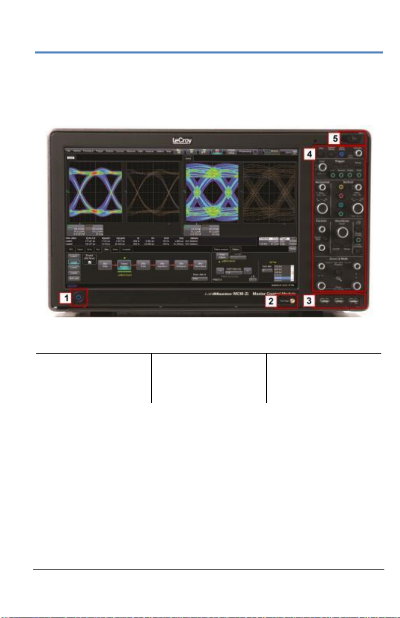
Number and Description
1. Power Button
2. Fast Edge Output
3. Host USB Ports
4. Detachable Front
Panel Control
5. Front Panel Control
Release Switch
Front of MCM-Zi Master Control Module
The MCM-Zi Master Control Module includes Controls, Display, CPU, and
ChannelSync Clock Architecture. All acquisition capability is contained in
separate Acquisition Modules.
Page 18

LabMaster 10 Zi Oscilloscopes
10
922561-00 Rev A
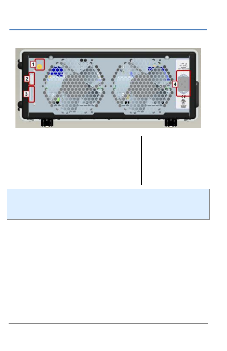
Number and Description
1. ChannelSync Outputs -
SMA 10 GHz Clock and
PCIe 1 Lane Control
Connections (for
corresponding
Acquisition Modules)
2. 10 MHz Reference Clock
Output
3. 10 MHz Reference
Clock Input (Grounded
EMI Shield required
when not in use)
4. Removable Storage
Drive
5. AC Power Inlet
6. The I/O Panel
7. DVI-D Video Output
8. PCIe 4 Lane Data
Inputs (from
corresponding
Acquisition
Modules)
Back of MCM-Zi Master Control Module
PLEASE NOTE THE FOLLOWING:
Cap-off unused ChannelSync SMA sockets (item 1) using the provided
chain-linked 50 Ω terminations (not shown).
10 MHz Reference Clock Inputs are specifically intended for
synchronization with other instruments; not between Master Control
Module and Acquisition Modules.
DVI-D Video Output is for use with an additional external monitor for
Extended Desktop mode.
Page 19
Getting Started Manual
922561-00 Rev A
11
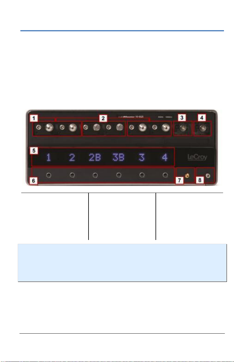
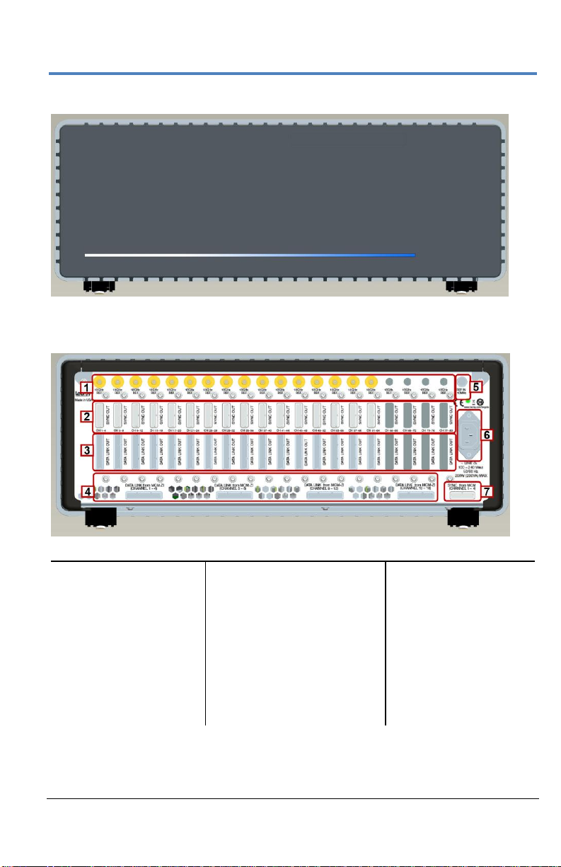
Number and Description
1. 2.92 mm Inputs
2. 1.85 mm Inputs
(>36 GHz models)
3. AUX IN
4. AUX OUT
5. Channel Number
Indicators
6. Channel ON/OFF
Buttons
7. Fast Edge Output
8. Ground connection
for wrist strap
The AUX IN connection is for 50 Ω input only.
The PCIe 4 Lane Data Inputs (item 8) also accommodate PCIe
Expansion Slot options for GPIB and LSIB. Option cards must be
specified when ordering and installed at the Teledyne LeCroy factory
into any number of the same five slots used for the Acquisition
Modules.
Front of 10-xxZi Acquisition Module
NOTE: If your system runs multiple Acquisition Modules, for optimal channel access
and convenience, Teledyne LeCroy recommends stacking the modules on top of
each other on your bench, inside Teledyne LeCroy's available OC910 oscilloscope
cart, or inside of your own rack (modules must be specifically ordered for rack
mounting from the Teledyne LeCroy factory).
Page 20
LabMaster 10 Zi Oscilloscopes
12
922561-00 Rev A
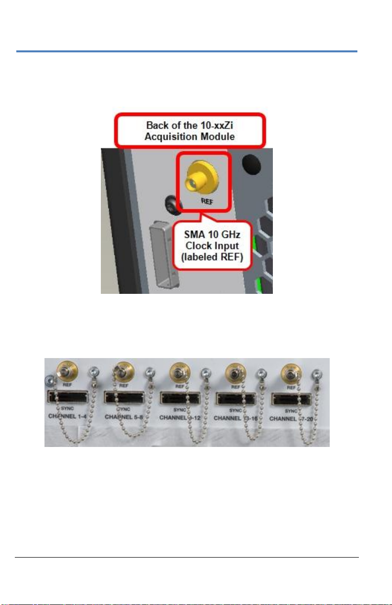
Number and Description
1. ChannelSync
SMA 10 GHz
Clock Input
2. ChannelSync
PCIe 1 Lane
Control Input
3. PCIe 4 Lane
Data Output
4. AC Power Inlet
Back of 10-xxZi Acquisition Module
NOTE: Only MCM-Zi Master Control Module has 10 MHz Reference Clock
Input/Output connections. 10 MHz Reference Clock Inputs are specifically intended
for synchronization with other instruments; not between Master and Acquisition
modules.
Page 21
Getting Started Manual
922561-00 Rev A
13
Number and Description
1. ChannelSync
SMA 10 GHz
Clock Output
2. ChannelSync
PCIe 1 Lane
Control Output
3. PCIe 4 Lane
Data Output
4. PCIe 4 Lane Data Input
(from MCM-Zi)
5. 10 MHz REF In
6. AC Power Inlet
7. ChannelSync PCIe 1
Lane Control Input
(from MCM-Zi)
Front of ChannelSync Mainframe Hub
Back of ChannelSync Mainframe Hub
Page 22
LabMaster 10 Zi Oscilloscopes
14
922561-00 Rev A
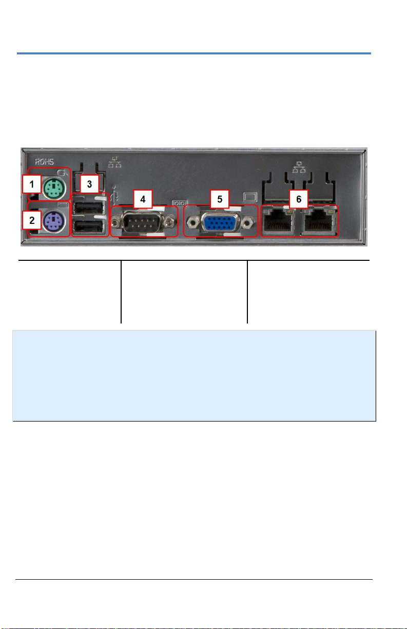
Number and Description
1. Mouse
2. Keyboard
3. Host USB Ports
4. 9-pin Serial Port
(disabled)
5. 15-pin Video Output
(disabled)
6. Ethernet ports (LAN)
Input/Output Panel
The available connections on I/O panels are the same for all LabMaster 10 Zi
configurations. I/O panels are located on the back of the Master Control
Module. See Back of MCM-Zi Master Control Module (on page 10) for more
information.
NOTE: The MCM-Zi motherboard is a server-class motherboard with certain I/O
capabilities (serial port, VGA/WXGA video output) that are not utilized by the MCMZi, even though the physical connectors remain on the I/O panel. The 9-pin serial
port is used for communication to the server motherboard, and the 15-pin video
connector only outputs text debug messages from the motherboard. Since these
capabilities are not useful for the MCM-Zi, they are disabled in the BIOS and will not
provide any I/O should you connect to them.
Page 23
Getting Started Manual
922561-00 Rev A
15
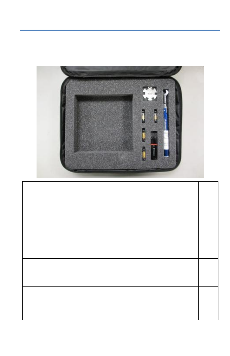
10dB Attenuators
(V-V)
Used instead of an internally switched attenuator
for optimal signal fidelity. Needed when >640mVpp signals (>80 mV/div) are input to the acquisition
module.
Qty. 2
V-female to V-female
Barrel Adapters
The native high bandwidth (50-65 GHz) connection
is a male connection. These barrel adapters
provide ability to make a male connection to the
high bandwidth inputs.
Qty. 2
Hand Wrench
Used to stabilize female-female barrel adapter
when attaching it to the high BW
V-male connector. Do not use this to tighten!
Qty. 1
Torque Wrench
Used to tighten or loosen the V-female barrel
adapter from the high bandwidth V-male connector.
It should also be used to tighten cables to the Vfemale barrel adapter.
Qty. 1
USB Memory Stick
This contains s-parameter files for the 10 dB
attenuators. A future capability to enter an sparameter file for the 10dB attenuator (should they
need to be replaced) will be provided so as to
optimize signal fidelity of the high bandwidth inputs.
Qty. 1
Standard High Bandwidth Accessories
The following accessories are delivered in a soft accessory case (SAC-01A)
with 50-65 GHz acquisition modules.
Page 24
LabMaster 10 Zi Oscilloscopes
16
922561-00 Rev A
LabMaster Setup
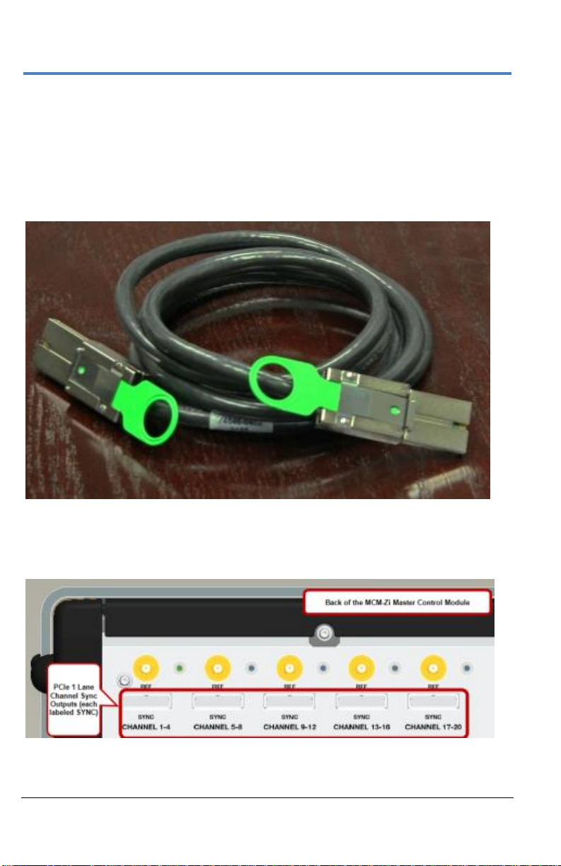
PCIe 1 Lane Cable SYNC Connection(s)
Connect each PCIe 1 Lane Control Input on the back of your 10-xxZi
Acquisition Modules to a PCIe 1 Lane Output on the MCM-Zi Master Control
Module using the PCIe 1 Lane cable(s) provided.
PCIe 1 Lane Cable
On the back of the Master Control Module, plug one end of the PCIe 1 Lane
cable into the PCIe 1 Lane Channel Sync Output (labeled SYNC).
Page 25
Getting Started Manual
922561-00 Rev A
17
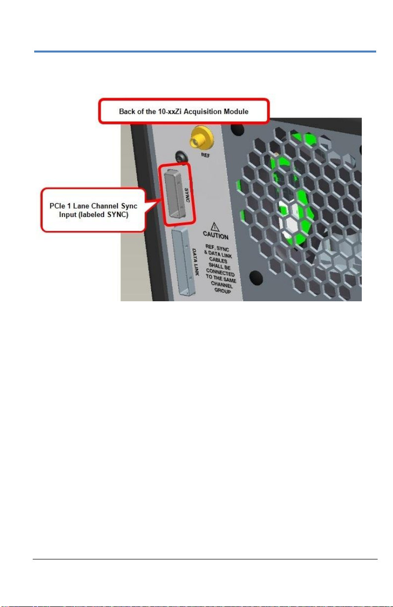
Now, connect the other end of the 1 Lane cable into the SYNC socket on the
back of the Acquisition Module.
Repeat these steps for every additional Acquisition Module in your system.
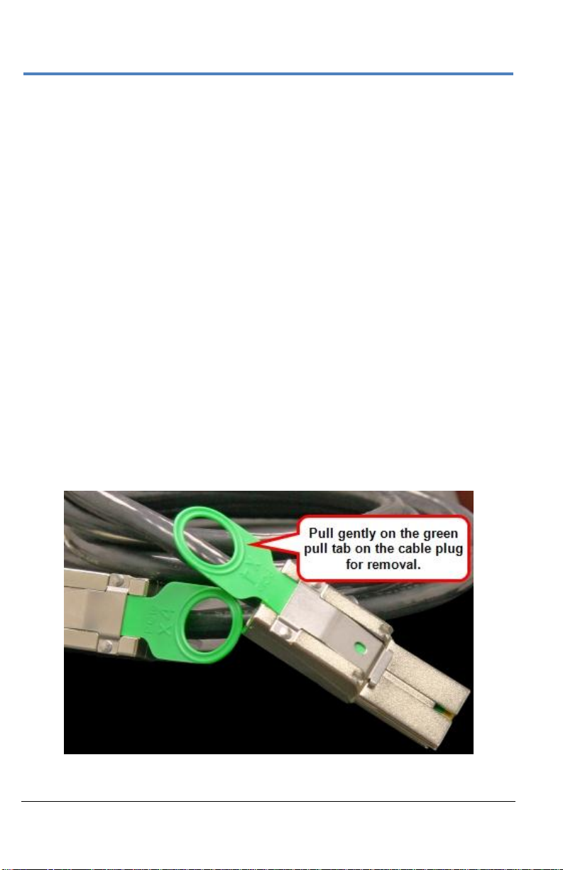
PLEASE NOTE THE FOLLOWING:
PCIe 1 Lane Cable plugs are keyed with a single groove along one
wide side of the plug. The plug must be inserted into the socket with
the groove aligned properly.
Connect to your Acquisition Modules from the correct channel
groupings on the Master Control Module; meaning, your first
Acquisition Module is connected from the CHANNEL 1-4 output,
second from the CHANNEL 5-8 output, third from the CHANNEL 9-12
output, etc.
If you are connecting less than 5 Acquisition Modules, the PCIe 1
Lane Channel Sync Outputs on the back of the Master Control
Module may not be skipped and must be connected in consecutive
order into the PCIe 1 Lane Channel Sync Inputs on the back of the
corresponding acquisition modules.
Pull gently on the green pull tab on the cable plug for removal.
Page 26

LabMaster 10 Zi Oscilloscopes
18
922561-00 Rev A
PCIe 4 Lane DATALINK Connection(s)
Continue making PCI Express connections by cabling the PCIe 4 Lane Data
Output on the back of each 10-xxZi Acquisition Module to the PCIe 4 Lane
Data Inputs on the back of the MCM-Zi Master Control Module using the
cable(s) provided.
PCIe 4 Lane Cable
Page 27

Getting Started Manual
922561-00 Rev A
19
On the back of the Acquisition Module, connect a PCIe 4 lane cable to the
PCIe 4 Lane Data Output (labeled DATALINK).
Now, on the back of the Master Control Module, connect the other end of
the same PCIe 4 Lane cable into the corresponding PCIe 4 Lane Data Input
(labeled DATALINK CHANNEL).
Page 28
LabMaster 10 Zi Oscilloscopes
20
922561-00 Rev A
Repeat these steps for each Acquisition Module in your system.
PLEASE NOTE THE FOLLOWING:
PCIe 4 Lane Cable plugs are keyed with a single groove along one
wide side of the plug. The plug must be inserted into the socket with
the groove aligned properly.
Be sure to connect your Acquisition Modules to the correct channel
groupings on the Master Control Module; First Acquisition Module is
connected into DATALINK CHANNEL 1-4, second into the DATALINK
CHANNEL 5-9 input,
third into the DATALINK CHANNEL 9-12 input,
fourth into the DATALINK CHANNEL 13-16 input,
and last into the DATALINK CHANNEL 17-20 input.
If you are connecting less than 5 of the Acquisition Modules, the
PCIe 4 Lane Data Inputs on the back of the Master Control Module
may not be skipped and must be connected in consecutive order
from the PCIe 4 Lane Data Outputs on the back of the corresponding
slaves.
Pull gently on the green pull tab on the cable plug for removal.
Page 29
Getting Started Manual
922561-00 Rev A
21
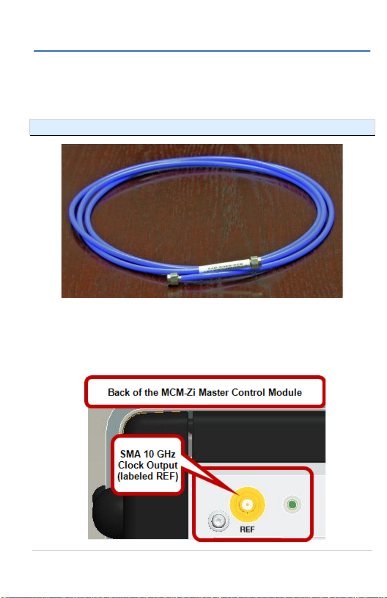
SMA 72" Cables - ChannelSync Clock
Usethe SMA 72" cable(s) provided to connect each SMA 10 GHz Clock
Output on the back of your MCM-Zi Master Control Module to the SMA 10
GHz Clock Input on each 10-xxZi Acquisition Module in your system.
NOTE: Use an SMA torque wrench to ensure connections are properly tightened.
SMA 72" Male to Male Cable
On the back of the Master Control Module, connect one end of an SMA 72"
cable from a SMA 10 GHz Clock Output (labeled REF, unscrew the chainlinked 50 Ω termination, if necessary) .
Page 30
LabMaster 10 Zi Oscilloscopes
22
922561-00 Rev A
Now, on the back of the Acquisition Module, connect the other end of the
same SMA 72" cable into the corresponding SMA 10 GHz Clock Input
(labeled REF).
Repeat the previous steps for every additional Acquisition Module in your
system.
Cap off unused SMA 10 GHz Clock Outputs on the back of your Master
Control Module using the chain-linked 50 Ω terminations provided.
Page 31

Getting Started Manual
922561-00 Rev A
23
ChannelSync Mainframe Hub
The CMH-20 ChannelSync Mainframe Hub provides a simple and effective
means to expand a LabMaster system beyond 20 channels (5 Acquisition
Modules). This is accomplished without any degradation of the timing
accuracy specifications. The Mainframe Hub is populated with cards for
each acquisition module (the back panel of the CMH-20 shown below is
populated with 20 cards for use with 20 Acquisition Modules, or 80 total
channels).
Connect a PCIe 1 Lane cable from the MCM-Zi Channel 1-4 output to the
single PCIe 1 Lane input at the lower right of the CMH-20 back panel.
Connect four PCle 4 Lane cables from the MCM-Zi data outputs for
channels 1-4, 5-8, 9-12, and 13-16 to the four PCIe 4 Lane data inputs along
the bottom of the CMH-20 back panel (to the left of the PCLe 1 input).
Connect from the PCIe 1 Lane Control, PCIe 4 Lane Data, and 10 GHz
ChannelSync Clock outputs to the corresponding inputs on the Acquisition
Modules.
Page 32

LabMaster 10 Zi Oscilloscopes
24
922561-00 Rev A
Power Cable and Main Power Switch
Teledyne LeCroy advises that you note the power ratings of the individual
modules and connect them to suitably rated circuits.
MCM-Zi Control Module comes with an IEC60320 Type C13 power
inlet connector.
LM10xx-Zi Acquisition Module comes with an IEC60320 Type C20
power inlet connector.
CAUTION: The combined draw from your Master Control Module
and Acquisition Modules (max of 20) can be many kilowatts. Two
acquisition modules connected to a single circuit may cause an overcurrent
condition for that circuit.
When all connections are made, the Standby Power switch on the front of
the Master Control Module powers on all components as a single unit.
NOTE: If any connections are incorrect, the switch will not power on the system.
Always refer to the product datasheet at www.teledynelecroy.com for the
most current and detailed specifications.
Page 33

Getting Started Manual
922561-00 Rev A
25
Touch Screen and External Displays
You may operate the instrument using the built-in touch-screen or attach an
external monitor for extended desktop operation. A properly configured
external touch-screen monitor will take on all the touch-screen capabilities
of the internal display.
NOTE: If the external monitor uses a Fujitsu touch screen driver, it will not work as a
touch screen but will support extended desktop operation.
To connect to an external monitor:
1. Choose File > Exit to close the oscilloscope application so that the
Windows desktop is visible (you do not need to shut down
completely).
2. Connect the oscilloscope to the external monitor from the DVI-D
video output connector.
3. Right-click on the desktop to display the settings menu, then choose
Screen Resolution.
4. On the Windows display dialog:
5. Use the Start DSO desktop icon to restart the oscilloscope
application.
6. Choose Display > Display Setup.
7. On the Display setup dialog, check Extend Grids on 2
The total number of grids is now distributed over both displays.
Select display number 2 (the external monitor) and choose
Multiple displays: Extend this display.
Drag the display number 2 icon to its location in your setup
(above or below the oscilloscope display).
Make any other desired display selections, then touch
Apply and OK.
nd
Monitor.
Page 34

LabMaster 10 Zi Oscilloscopes
26
922561-00 Rev A
Both displays before Dual Display Mode selection. In this example, the top monitor is
the external display.
Page 35

Getting Started Manual
922561-00 Rev A
27
Grids distributed after Dual Display Mode selection. Trace descriptor boxes move
with the trace (note the movement of C1-C4). Other controls remain on the primary
display (Display 1, which in this example is the bottom, internal display).
Page 36

LabMaster 10 Zi Oscilloscopes
28
922561-00 Rev A
Removing and Attaching the Front Panel
Detach the Front Panel Control from the oscilloscope by sliding the
detachment lever to the left and pulling at the right.
Page 37

Getting Started Manual
922561-00 Rev A
29
Attach the front panel by inserting the lower part first, sliding the
detachment lever to the left, and then pushing the top in place.
While detached, your front panel can be used as a remote control. Just
connect it to the oscilloscope using the USB - A to USB - Mini B cable
provided.
NOTE: While a standard front panel comes with your Zi oscilloscope, Teledyne
LeCroy offers additional standard front panels or a 4 channel version to better suit
the way you work.
Page 38

LabMaster 10 Zi Oscilloscopes
30
922561-00 Rev A
Signal Inputs
Probes
Teledyne LeCroy offers a variety probes for use with your oscilloscope. The
types compatible with the LabMaster 10 Zi are listed below. Visit
teledynelecroy.com for specifications and ordering information.
Single-Ended - A single-ended, active probe is associated with
measuring voltages at high frequencies. Measurement with an active
probe requires a test point and a ground point. The ground (also
called earth) acts as a zero reference for the test point measurement.
These probes are typically low-bandwidth and require an adapter to
connect to the 2.92 mm and 1.85 mm interfaces on the 10-xxZi
Acquisition Modules.
Differential Probes - Differential active probes are like two probes in
one. Instead of measuring a test point in relation to a ground point
(like single-ended active probes), differential probes measure the
difference in voltage of a test point in relation to another test point.
Some models of differential probes may require an adapter to
connect to the 2.92 mm and 1.85 mm interfaces on the 10-xxZi
Acquisition Modules.
Interfaces
LabMaster 10 Zi systems are equipped with a variety of interfaces to allow
you to connect cables directly to the oscilloscope channels, reducing the
need to use costly adapters that may be easily lost or misplaced.
The inputs power the probe and completely integrate the probe with the
oscilloscope channel in a number of ways:
Upon connection, the probe is recognized and some setup
information, such as input coupling and attenuation, is performed
automatically.
System (probe plus oscilloscope) gain settings are automatically
calculated and displayed based on the probe attenuation.
Page 39

Getting Started Manual
922561-00 Rev A
31
Most active probes match probe to oscilloscope response
automatically using probe response data stored in an on-board
EEPROM. This ensures the best possible combined probe plus
oscilloscope channel frequency response without the need to
perform any de-embedding procedure.
Interfaces differ in bandwidth capabilities, so the interfaces contained on
your oscilloscope—and their exact location—depend on the bandwidth
rating of the oscilloscope model you purchased.
High-bandwidth interfaces ( 45 GHz and up) must be enabled by selecting
the appropriate Dual Bandwidth Interleave setting on the Timebase dialog
and the Input B setting on the Channel dialog.
ProBus Interface
LabMaster 10xxZi Acquisition Modules rated to 36 GHz use the ProBus
interface for AUX In and AUX Out connections. These connectors are
located on the front of the unit next to the channel inputs.
The ProBus interface contains a 6-pin power and communication connection
and a BNC signal connection to the probe. It offers both 50 Ω/1 MΩ input
impedance and provides probe power and control for a wide range of
probes such as high impedance passive probes, high impedance active
probes, current probes, high voltage probes, and differential probes. ProBus
also includes sense rings for detecting passive probes. The ProBus interface
may also have a BNC-terminated cable connected directly to it.
ProBus is based on a BNC connector and, depending on the exact BNC
connector used and the oscilloscope design, is rated for up to 4 GHz with 50
Ω coupling or up to 1 GHz for 1 MΩ coupling.
2.92 mm Interface
All LabMaster 10xxZi Acquisition Modules use the 2.92 mm interface to
input signals up to 36 GHz on channels 1-4, input A. This interface consists
of a precision connector and a LEMO power and communication connector.
It offers 50 Ω input impedance only.
Page 40

LabMaster 10 Zi Oscilloscopes
32
922561-00 Rev A
The 2.92 mm high-bandwidth electrical paths are comprised of two
connector halves/subassemblies which have a common mating interface:
The first connector half is mounted onto the oscilloscope connector
panel. The outer end of this connector has a combination of
grooves, external threads and a coaxial interface with a 2.92 mm
airline geometry.
The second connector half is the connector saver. It has a similar
interface on one end, with spring-biased inner and outer contacts.
The connector saver has projections which interlock with slots on the
mounted connector and a coupling nut which secures the two halves;
resulting in a non-rotational, torque independent electrical connection. The
spring-biased inner and outer contacts eliminate the need for specifying
proof torque and no tools are required to mate or un-mate the connection.
The connector saver is easily field replaceable, should damage occur,
making it a more field reliable system. The 2.92 mm connector saver
operates mode free well beyond 36 GHz.
1.85 mm Interface
LabMaster 10xxZi Acquisition Modules rated over 36 GHz use the 1.85mm
interface for 50-65 GHz inputs (channels 2 and 3, input B). This interface
consists of a precision V-male connector with a V-female to V-female barrel
adapter and a LEMO power and communication connector. It offers 50 Ω
input impedance only. The barrel adapter is easily field replaceable, should
damage occur.
The male connector is mounted onto the oscilloscope connector panel
when delivered. The female-female barrel adapter must be manually
attached before connecting cables.
Page 41

Getting Started Manual
922561-00 Rev A
33
To attach the female-female barrel adapter:
1. Remove the white cap from the V-male connector on the high
bandwidth input of the 10-xxZi acquisition module. Turn it
counterclockwise to loosen it.
2. Insert the female-female barrel adapter into the V-male connector.
Page 42

LabMaster 10 Zi Oscilloscopes
34
922561-00 Rev A
3. Gently turn the V-male connector in the counterclockwise direction
until it is finger tight.
4. Insert the hand wrench over the flat portion of the barrel adapter.
This will hold the barrel adapter still while the V-male connector is
tightened around it.
Page 43

Getting Started Manual
922561-00 Rev A
35
5. Tighten the V-male connector around the female-female barrel
adapter using the torque wrench in a counterclockwise motion.
CAUTION. Hold the torque wrench at the end or you may apply too
much force. When the torque wrench bends at the moment arm, it
is tightened to the right amount of force. Do not tighten further.
6. Connect a cable to the barrel adapter, and use the torque wrench to
tighten it.
To remove the female-female barrel adapter: Reverse the steps above,
turning the V-male connector clockwise to loosen it. Be sure to turn the Vmale connector and not the barrel adapter. You may have to manually keep
the torque wrench from bending while loosening the connector.
Probe Dialog
Teledyne LeCroy proprietary probe interfaces provide a complete
measurement solution from probe tip to oscilloscope display. The Probe
Dialog displays probe attenuation and other information, and allows you to
make tip select and other probe settings from the oscilloscope touchscreen.
The following figure shows a typical channel dialog on a Teledyne LeCroy
oscilloscope containing both 2.92 mm (Input A) and 1.85 mm (Input B)
interfaces. The input selection is on the left-hand side of the dialog box.
Page 44

LabMaster 10 Zi Oscilloscopes
36
922561-00 Rev A
When the probe is not connected, there is only a C1 tab selection for
vertical channel setup and the user has the ability to select input coupling
and probe attenuation.
Channel dialog showing Input A's interface controls setup before connection.
After a probe is connected, it is recognized and an additional tab with the
probe model name is displayed to the right of the C1 tab. Click on the tab or
the probe field to display the probe dialog.
Channel dialog showing Input A's interface controls setup after connection.
This additional tab contains specific information on the connected probe.
Default values for the probes coupling and attenuation are automatically
downloaded from the probe, and these settings along with other attributes
are shown on the dialog.
The probe dialog showing the connected probe's control attributes.
Page 45

Getting Started Manual
922561-00 Rev A
37
Basic Controls
Front Panel Control Groups
Many Front Panel controls directly correspond with Screen Layout Controls.
For example, the Print front panel button is associated with one of the
Hardcopy function at Utilities → Utilities Setup → Hardcopy.
Page 46

LabMaster 10 Zi Oscilloscopes
38
922561-00 Rev A
Miscellaneous Controls / WaveStream Indicator
Help - Opens the Teledyne LeCroy Online Assistant. If the second
monitor is installed, the online help opens on the second monitor.
Default Setup - Resets the oscilloscope's settings to the default
configuration. Corresponds with screen menu selection: File → Recall
Setup → Recall Default Setup.... For a list of default settings, see
Save/Recall → Saving and Recalling Setups (on page 140).
Auto Setup - Opens the Auto Setup... flyout menu.
Press the Auto Setup... button on the flyout menu to
perform a full auto setup. Press a Channel Find Scale
button on the flyout menu to perform a quick auto
setup for that channel only. Press the AUTO SETUP... front panel
button twice to perform the last selection from the Auto Setup...
flyout menu (the default is to perform a full auto setup).
If Auto Setup is run when no channels are turned on, all channels are
affected. When more than one channel is turned on, the first channel
with a signal applied to it is automatically set up for edge triggering.
WaveStream - Indicates when WaveStream mode is ON.
Intensity - Toggles between WaveStream OFF and ON for Analog
Persistence and WaveStream ON for Color Persistence. When you
turn the knob, if WaveStream is ON, the WaveStream display
intensity changes. When you turn the knob, if WaveStream is OFF,
changes the Intensity setting. Corresponds with the screen menu
selection: Display → Display Setup (on page 95).
Page 47

Getting Started Manual
922561-00 Rev A
39
Trigger Front Panel Controls
Level – Sets the trigger level to 50%. Turn the knob to change the
trigger threshold level. The threshold level is indicated on the Trigger
label.
READY and TRIG'D Indicators - The READY indicator is lit when the
trigger is armed. TRIG'D is lit momentarily when a trigger occurs. A
fast trigger rate causes the light to stay lit continuously.
Setup - Opens the Trigger Setup... dialog. Corresponds with screen
menu selection: Trigger → Trigger Setup.... Press the Trigger SETUP
front panel button again to close the Trigger Setup... dialog.
Auto - Turn on Auto Trigger mode, which triggers the oscilloscope
after a time-out, even if the trigger conditions are not met.
Normal - Turn on Normal Trigger mode, which triggers the
oscilloscope each time a signal is present that meets the conditions
set for the type of trigger selected.
Single - Turn on Single Trigger mode, which arms the oscilloscope to
trigger once (single-shot acquisition) when the input signal meets the
trigger conditions set for the type of trigger selected. If the scope is
already armed, it will force a trigger.
Stop Prevent the scope from triggering on a signal. If you boot up the
instrument with the trigger in Stop mode, a no trace available
message is shown. Press the Trigger AUTO front panel button to
display your trace.
Page 48

LabMaster 10 Zi Oscilloscopes
40
922561-00 Rev A
Horizontal Front Panel Controls
Note: Horizontal front panel controls correspond with screen menu selection:
Timebase → Horizontal Setup....
Delay - Toggles between a zero horizontal delay value and the
previous horizontal delay value. Turn to change the horizontal delay
value.
Time/Div - Sets the time/division of the oscilloscope timebase
(acquisition system).
Vertical Front Panel Controls
NOTE: You can turn channels on and off using the software as explained in Vertical
Overview (on page 67) or from the front of the LabMaster Acquisition Module.
Page 49

Getting Started Manual
922561-00 Rev A
41
Channels – Control channel ON/OFF and which channel is active for
the Vertical Offset and Volts/Div knobs controls. If a channel is OFF,
pressing that channel button turns it on and makes it active. If a
channel button is ON, pressing that channel button makes it active,
and then pressing it a second time turns it OFF.
Offset - Toggles between a zero vertical offset value and the previous
vertical offset value for the selected channel. Turn to change the
vertical offset value for the selected channel.
Gain - Toggles between fixed and variable gain adjustment. Turn to
change the gain value.
NOTE: Front panel Channel buttons are only lit when Channels 1 through 4 are
active; however, Gain and Offset knobs will control any channels from any
connected acquisition module. Touch the display Trace Descriptor Label to activate
the channel before using the front panel knobs to make desired Gain and Offset
adjustments.
Zoom and Math Front Panel Controls
NOTE: Zoom and Math front panel controls correspond with screen menu selection:
Math → Zoom Setup....
Horizontal Position - Resets the horizontal zoom position to zero.
Turn to change the horizontal position of the selected math or zoom
trace.
Horizontal Ratio - Toggles between fixed and variable horizontal
zoom ratio adjustment. Turn to change the horizontal zoom ratio of
the selected math trace.
Page 50

LabMaster 10 Zi Oscilloscopes
42
922561-00 Rev A
Quick Zoom - Automatically displays magnified views of up to four
signal inputs on multiple grids. With four input signals, the signals are
displayed along with four zoom traces, each on its own grid. Pressing
this button also turns off all other traces.
Vertical Position - Resets the vertical zoom position to zero. Turn to
change the vertical position of the selected math or zoom trace.
Vertical Ratio - Toggles between fixed and variable vertical zoom
ratio adjustment. Turn to change the vertical zoom ratio of the
selected math trace.
Display Dashboard
Screen Layout, Groupings, and Controls
The instrument's screen is divided into the following main sections:
Menu Bar
Signal Display Grid
Descriptor Labels
Dialog(s)
The Message Bar
NOTE: Many front panel controls directly correspond with screen layout controls.
For example, the Print front panel general control button corresponds with the
Hardcopy function set from Utilities → Utilities Setup → Hardcopy.
Page 51

Getting Started Manual
922561-00 Rev A
43
Menu Bar
The top of the screen contains a menu bar of commonly used functions.
Whenever you touch one of these buttons and make a selection from its
drop-down menu, the dialog area at the bottom of the screen displays the
corresponding dialog.
Specific Menu Bar functions are referenced using arrow-separated path
descriptions. For example, the Save Setup function is referenced as File →
Save Setup....
NOTE: For common oscilloscope operations, you don't need to use the top menu
bar (since you can access most dialogs from the Front Panel or from the Descriptor
Labels). However, it is the only way to access setup or other dialogs for Display
Setup, Save or Recall Waveform, Save or Recall Setups, Print Setup, Vertical
(Channel), Horizontal, or Trigger Status, Memory (Reference Waveform) Setup,
Pass/Fail Setup, or Utilities and Preferences Setup....
Quick Access Toolbar
The Quick Access toolbar is located on the right side of the menu bar. You
can use these toolbar buttons to quickly access Trigger, Processing and
Undo functionality.
QUICK ACCESS TRIGGER FUNCTIONS
Auto - Press to turn on Auto Trigger mode, which triggers the
oscilloscope after a time-out, even if the trigger conditions are not
met.
Normal - Press to turn on Normal Trigger mode, which triggers the
oscilloscope each time a signal is present that meets the conditions
set for the type of trigger selected.
Single - Press to turn on Single Trigger mode for the selected
channel, which arms the oscilloscope to trigger once (single-shot
acquisition) when the input signal meets the trigger conditions set for
the type of trigger selected. If the oscilloscope is already armed, it
forces a trigger.
Page 52

LabMaster 10 Zi Oscilloscopes
44
922561-00 Rev A
Stop - Press to prevent the oscilloscope from triggering on a signal. If
you boot up the instrument with the trigger in Stop mode, the
message "no trace available" is shown.
Trigger Setup - Press to open the Trigger Setup... dialog. Corresponds
with screen menu selection: Trigger → Trigger Setup....
QUICK ACCESS PROCESSING FUNCTIONS
The Processing section allows you to suspend your system from processing
data. You can stop data processing, make adjustments, and then resume
data processing with the touch of two on-screen buttons.
Touching the Stop button shows the Processing Paused... pop-up.
Touch the Resume button to continue processing data.
QUICK ACCESS UNDO FUNCTION
At times, an Undo button is made available to the right of the Quick Access
Toolbar on the Menu Bar. The Undo button is labeled with the most recent
action, so you are aware of the specific function prior to reversal.
Page 53

Getting Started Manual
922561-00 Rev A
45
The Signal Display Grid
The grid area is divided into 8 vertical divisions and 10 horizontal divisions
just like any other oscilloscope. Set up the signal display area by touching
Display → Display Setup... from the menu bar. The Display dialog offers a
choice of grid combinations and can also set the grid intensity.
There are several indicators on the grid to help you understand the
following:
Trigger Delay - This indicator is located along the
bottom edge of the grid. Trigger delay allows you to
see the signal prior to the trigger time.
All trigger delay values (including post-trigger delay,
shown here) are displayed in the Timebase
Descriptor Label. Zero delay is the horizontal center
of the oscilloscope display.
The default setting (Time) is for delay readout (in seconds) and to move
proportionately when the timebase knob is turned. If you want to set delay
(Div) to a fixed position on the grid, and then have it stay fixed as the
timebase changes, go to Utilities → Preference Setup... and select the
Acquisition dialog to make the setting.
Post-trigger Delay - This is indicated by a left-
pointing arrow to the lower-left of the grid. Pretrigger delay is indicated by a right-pointing arrow to
the lower-right of the grid.
Trigger Level - This indicator is located at the right
edge of the grid. It tracks the trigger level as you
reposition the trace up or down, or change scale.
When triggering is stopped, a hollow arrow indicates
Page 54

LabMaster 10 Zi Oscilloscopes
46
922561-00 Rev A
where the new level ends up when triggering resumes. Push the LEVEL knob
to reset the level to 50%.
Zero Volts Level - This indicator is located at the left
edge of the grid. Change the zero volts level by
turning the vertical OFFSET knob. Push the knob to
reset the indicator to the middle of the grid.
SIGNAL DISPLAY GRID POP-UP MENU
On the Signal Display Grid, the Pop-up menu provides
assistance while using the oscilloscope.
Clicking on a waveform opens a pop-up menu. From this
pop-up menu, you can perform the following functions:
Open the Setup dialog for the trace
Turn the trace descriptor label off
Open the Math dialog for the trace
Open the Measure dialog for the trace
Annotate the selected trace
Trace Descriptor Labels
Shown just beneath the grid display, these boxes provide a summary of your
channel, timebase, and trigger settings.
When a trace is selected its corresponding descriptor label is shown
highlighted.
The C1 Trace Descriptor Label is selected; C2 is not.
Make vertical or horizontal channel adjustments by touching the respective
label. The setup dialog for the function is shown beneath.
Channel trace labels show the vertical settings for the trace and cursor
information (if cursors are in use). The title bar of the label includes
indicators for (SinX)/X interpolation, waveform inversion (INV), deskew
Page 55

Getting Started Manual
922561-00 Rev A
47
(DSQ), coupling (DC/GND), bandwidth limiting (BWL), and averaging (AVG).
These indicators have a long and short form, respectively.
The long and short forms of trace descriptor indicators.
Besides channel traces, math and parameter measurement labels are also
displayed. Labels are displayed only for traces that are turned on.
Vertical and horizontal trace descriptor (labels) are displayed below the grid.
They provide a summary of your channel, timebase, and trigger settings.
Make vertical or horizontal channel adjustments by touching the respective
label. The setup dialog for the function is shown beneath.
TimeBase trace descriptor labels show the trigger
delay setting, time per division, and sampling
information.
Setup information for horizontal cursors,
including the time between cursors and
the frequency, is shown beneath the TimeBase and Trigger trace descriptor
labels.
Trigger trace descriptor labels show the trigger mode
(Auto, Normal, or Stopped). It also shows the coupling
(DC), trigger type (Edge), source (C1), level (0 mV), and
slope (Positive).
Page 56

LabMaster 10 Zi Oscilloscopes
48
922561-00 Rev A
SHORTCUT BUTTONS
You can access the same functions as available from the Signal Display Grid
Pop-Up menu by touching a trace-descriptor label to open the setup dialog.
From the setup dialog, shortcut buttons enable you to:
Open the Math dialog for the trace.
Open the Measure dialog for the trace.
Annotate the selected trace.
ANNOTATING TRACES
The instrument gives you the ability to add an identifying label, bearing your
own text, to a waveform display:
For each waveform, you can create multiple labels and turn them all on or
all off. Also, you can position them on the waveform by dragging or by
specifying an exact horizontal position.
On the display grid, touch the waveform you want to annotate, then touch
Set label... on the pop-up menu. A dialog box opens in which to create the
label. The first time creating a waveform label, Label1 is provided as default
text when the Add label button is touched.
Page 57

Getting Started Manual
922561-00 Rev A
49
From this pop-up you can edit existing annotations, change the label
placement on the waveform, add labels, remove labels, and toggle the
visibility.
If you are modifying an existing label, under Labels touch the label
you want to change.
NOTE: If the Channel dialog for the trace you want to annotate is currently
displayed, touch the Label button at the bottom to display the Trace
Annotation setup dialog. You may place a label anywhere you want on the
waveform. Labels are numbered sequentially according to the order in
which they are added, and not according to their placement on the
waveform.
If you want to change the label's text, touch inside the Label Text
field. A pop-up keyboard appears for you to enter your text. Touch
O.K. on the keyboard when you are done. The edited text
automatically appears in the label on the waveform.
Precisely place the label by touching inside the Horizontal Pos. field
and provide a horizontal value, using the pop-up numeric keypad.
Add another label by touching the Add label button. Delete a label by
selecting the label from the list, and then touching the Remove label
button.
Make labels visible by touching the View labels checkbox.
Page 58

LabMaster 10 Zi Oscilloscopes
50
922561-00 Rev A
Dialog Area
The lower portion of your oscilloscope screen is where information is
shown, selections are made, and data is input. These screens are organized
into tabular displays, subtabs, or pop-up dialogs. The dialog area is
controlled by Touch Screen Controls and Front Panel Controls.
POP-UP SELECTOR CONTROLS
When Pop-Up selector controls are touched, sometimes a very small box is
shown right inside the control - as in the following control for Coupling on
the C1 dialog.
Other times, a larger box is shown after touching a control. This larger PopUp has categorical buttons along the left column along with labels (and
sometimes descriptions) for the selectable entry values.
Page 59

Getting Started Manual
922561-00 Rev A
51
TEXT ENTRY CONTROLS
For most entry fields, touch once then enter a value using an attached
keyboard (or double-touch/click to use the Virtual keyboard).
FOLDER/FILE BROWSING CONTROLS
These controls allow for navigation to or from folders (on the hard drive or
memory device) for retrieving or storing items such as waveforms,
LabNotebook entries, to name a few.
Page 60

LabMaster 10 Zi Oscilloscopes
52
922561-00 Rev A
NOTE: The instrument's hard disk is partitioned into C: and D: drives. Drive C:
contains the Windows operating system and the instrument application software.
Drive D: is intended for data files.
FLYOUT MENU CONTROLS
Flyout Menus provide additional options for a particular font panel control.
A set of touch screen buttons appear at the right-side of the display. An
example Flyout Menu is seen when you press the Setup front panel button.
PRECISION DATA ENTRY CONTROLS
Certain fields requiring precise value entry assist you by having precision
entry means. When these controls are selected, you can provide values as
follows:
Slider Bar
Some models provide what is known as a Slider Bar along the bottom of the
screen when a keyboard is attached to the instrument. The Slider Bar
allows you to select your entered value by moving a horizontal slider (left to
right provides low to high amounts).
Page 61

Getting Started Manual
922561-00 Rev A
53
Pop-Up Keypad
Some models provide a pop-up Keypad when you touch twice in the same
control. For many controls, the Front Panel Controls (on page 16) can be
used to adjust the value in the pop-up.
The Pop-Up contains Up and Down arrow buttons, Set to Max, Default, and
Min buttons, and the Keypad itself for providing your value.
When the slider bar is shown, Default and Keypad buttons are provided for
quickly entering a default value or to use the pop-up keypad, respectively.
Shortcut Buttons
Several dialogs contain a row of buttons at the bottom of the dialog. These
provide a shortcut to common functions without having to leave the
underlying set up dialog. These shortcut buttons at the bottom of the
Channel Setup dialog perform the following functions.
Page 62

LabMaster 10 Zi Oscilloscopes
54
922561-00 Rev A
Measure - Opens the Measure menu. You can then select a
parameter from this menu without leaving the Channel Setup dialog.
The parameter automatically appears below the grid.
Zoom - Creates a zoom trace of the channel trace whose dialog is
currently displayed.
Math - Opens the Math menu. You can then select a math function
from this menu without leaving the Channel Setup dialog. A math
trace of the channel whose dialog is currently open is automatically
displayed.
Decode - Opens the main Serial Decode dialog where protocol option
measurements can be applied to signals.
Store - Loads the channel trace into the next available memory
location (M1 to M4).
Find Scale - Automatically performs a vertical scaling that fits the
waveform into the grid.
Next Grid - Automatically moves the channel trace whose dialog is
currently open onto the next grid. If you have only one grid
displayed, a new grid will be created automatically, and the trace
moved.
Label - Enables you to attach identifying labels to your waveforms.
The labels are preserved when the waveform is saved as a
LabNotebook entry and when saved to file.
Probe Cal - Cable Deskew - Opens the Probes Cal. dialog where
various Gain, Offset, Skew, Source, and Advanced controls are
available for probe signal calibration.
These shortcut buttons at the bottom of the Px dialogs display special traces
associated with these Math functions:
Page 63

Getting Started Manual
922561-00 Rev A
55
Message Bar
At the bottom of the oscilloscope display is a narrow message bar. The
current date and time are displayed at the far right. Status, error, or other
messages are also shown in this area.
Turning On Traces
To turn on a trace, do one of the following:
Press the front panel Channel buttons (1-4).
Press the channel buttons on the front of your Acquisition Modules
to turn channels on/off.
From menu bar, choose Vertical > Channel <#>.
A trace descriptor box appears on the display for each open channel trace.
When you touch this descriptor box, the trace is activated and the Channel
(C#) dialog opens.
A highlighted descriptor box indicates the active trace to which all actions
apply. Touch this box at any time to open its setup dialog.
NOTE: The default is to display each trace on its own grid automatically (Auto Grid).
To change how traces are arranged, choose another grid option from the Display
menu.
You can also quickly create (and turn on the descriptor box for) math and
memory traces without leaving the Channel dialog by touching the Measure
and Math icons at the bottom.
Whenever you activate a channel, math, or memory trace, the dialog at the
bottom of the screen automatically switches to the appropriate setup dialog
for that selection. The tab is labeled with the corresponding channel
number:
Page 64

LabMaster 10 Zi Oscilloscopes
56
922561-00 Rev A
Timebase
Timebase Dialog
You can access Timebase settings by:
Using the front panel Horizontal controls,
Choosing Timebase → Horizontal Setup... from the menu bar
Touching the Timebase trace descriptor label.
The main Timebase dialog contains sections for choosing Sampling Mode,
Timebase Mode, and Real Time Memory.
A section specifically used for Combining Channels (below) is located at the
far right of the main Timebase dialog. This section varies based on your
oscilloscope model.
Combining Channels
Digital Bandwidth Interleave (DBI) is a method for combining channels to
double or triple bandwidth, sample rate, and memory lengths - just as
oscilloscope manufacturers have for years interleaved channels to increase
sample rate and memory.
When you make DBI selections, some system values are changed. View
these changes by touching the trace descriptor label for an interleaved
channel. In particular, The Vertical Scale B Scale V/div (Timebase) value is
automatically set to 50 mV/div. If you set this to a different value after
deactivating DBI, the system resumes the last one used with DBI when DBI is
reactivated.
Page 65

Getting Started Manual
922561-00 Rev A
57
1. Choose TimeBase → Horizontal Setup... to access the Timebase
dialog.
2. If you have more than one Acquisition module, touch the DBI tab to
show the DBI dialog. Otherwise, use the Digital Bandwidth Interleave
area to the far right of the Timebase dialog.
3. Select the inputs to combine by touching the corresponding higher
bandwidth button beneath the pair (in the image below, 36 GHz C1
and C2 are combined into one 65 GHz C2). The active input is
highlighted. Combinations can be made in one or all modules.
4. The respective channels are combined into higher bandwidth
channels, labeled "Input B".
5. On the Channel setup dialog, select Input B.
NOTE: Use Channel 4 for high-speed serial triggering, even in cases where the
oscilloscope is operating in 50, 60, or 65 GHz modes.
Page 66

LabMaster 10 Zi Oscilloscopes
58
922561-00 Rev A
Sampling Modes
Depending on your timebase, you can choose:
Real Time Sampling Mode (below) - Also known as single-shot sampling
mode, a series of digitized voltage values sampled on the input signal at a
uniform rate.
Sequence Sampling Mode (on page 59) - Many trigger events stored as
segments into the oscilloscope's memory.
Selecting a Sampling Mode
1. Touch Timebase → Horizontal Setup... from the menu bar.
2. On the Timebase dialog, select a Sample Mode.
3. If you chose Sequence Mode, touch the Sequence tab and provide
values for Number of Segments, Enable Timeout, Timeout (value),
Display Mode, and Show Sequence Trigger Times.
Single-shot Sampling Mode
A single-shot acquisition is a series of digitized voltage values sampled on
the input signal at a uniform rate. It is also a series of measured data values
associated with a single trigger event. The acquisition is typically stopped a
defined number of samples after this event occurs: a number determined by
the selected trigger delay and measured by the timebase. The waveform's
horizontal position (and waveform display in general) is determined using
the trigger event as the definition of time zero.
You can choose either a pre- or post-trigger delay. Pre-trigger delay is the
time from the left-hand edge of the display grid forward to the trigger
event, while post-trigger delay is the time back to the event. You can sample
the waveform in a range starting well before the trigger event up to the
moment the event occurs. This is 100% pre-trigger, and it allows you to see
the waveform leading up to the point at which the trigger condition was
met and the trigger occurred. (The instrument offers up to the maximum
record length of points of pre-trigger information.) Post-trigger delay, on
Page 67

Getting Started Manual
922561-00 Rev A
59
the other hand, allows you to sample the waveform starting at the
equivalent of 10,000 divisions after the event occurred.
On fast timebase settings, the maximum single-shot sampling rate is used.
But for slower timebases, the sampling rate is decreased and the number of
data samples maintained.
The relationship between sample rate, memory, and time can be simply
defined as:
Capture Interval = 1/Sample Rate X Memory
and
Capture Interval/10 = Time Per Division
Sequence Sampling Mode – Working with Segments
Using Sequence Mode, thousands of trigger events can be stored as
segments into the oscilloscope's memory (the exact number depends on
oscilloscope model and memory options). This is ideal when capturing many
fast pulses in quick succession or when capturing few events separated by
long time periods. The instrument can capture complicated sequences of
events over large time intervals in fine detail, while ignoring the
uninteresting periods between the events. You can also make time
measurements between events on selected segments using the full
precision of the acquisition timebase.
Sequence mode offers a number of unique capabilities:
You can acquire up to four channels simultaneously.
You can minimize dead time between trigger events for consecutive
segments.
You can view time stamps for acquisitions.
You can zoom segments or used them as input to math functions.
You can combine sequence mode with an advanced trigger to isolate
a rare event, capture all instances over hours or days, and
view/analyze each afterwards.
Page 68

LabMaster 10 Zi Oscilloscopes
60
922561-00 Rev A
You can use Sequence mode in remote operation to take full
advantage of the instrument's high data-transfer capability.
In Sequence mode, the complete waveform consists of a number of fixedsize segments acquired in single-shot mode (see the instrument
specifications for the limits). The oscilloscope uses the sequence timebase
setting to determine the capture duration of each segment as 10 x time/div.
With this setting, the oscilloscope uses the desired number of segments,
maximum segment length, and total available memory to determine the
actual number of samples or segments, and time or points.
How the instrument captures segments
Page 69

Getting Started Manual
922561-00 Rev A
61
SEQUENCE DISPLAY MODES
The instrument gives you a choice of five ways to display your segments:
Adjacent
Waterfall (cascaded)
Mosaic (tiled)
Overlay
Perspective
NOTE: some display modes have limitations on the number of segments that can
be shown at one time.
Page 70

LabMaster 10 Zi Oscilloscopes
62
922561-00 Rev A
SEQUENCE MODE SETUP
When setting up Sequence Mode, you define the number of fixed-size
segments acquired in single-shot mode (see the instrument specifications
for the limits). The oscilloscope uses the sequence timebase setting to
determine the capture duration of each segment. Along with this setting,
the oscilloscope uses the number of segments, maximum segment length,
and total available memory to determine the actual number of samples or
segments, and time or points.
Setting up Sequence Mode (Adjacent)
1. Touch Timebase → Horizontal Setup... on the menu bar.
2. Click the Sequence tab.
3. Under Acquisition Settings, touch inside the Num Segments data
entry control and provide a value using your preferred input control
method. Additional information on using the touch screen controls
can be found in the Dialog Area.
NOTE: The number of segments you choose to display can be less than the
total number of segments in the waveform. For example, in the pop-up
images above, the number of display segments is 10, but the total number
of segments entered in Num Segments on the Timebase dialog is 100.
Page 71

Getting Started Manual
922561-00 Rev A
63
4. Touch the Enable Timeout checkbox.
5. Touch the Timeout data entry control and provide a timeout value.
NOTE: Use the sequence mode timeout to automatically interrupt the
sequence acquisition if the timeout value is exceeded without a valid trigger.
The timeout period accounts for instances when a Num Segments
miscount occurs for some reason and the oscilloscope waits indefinitely for
an unforthcoming segment. During that time, no oscilloscope functions are
accessible. By means of a timeout value, however, the acquisition will be
completed, the waveform displayed, and control of the oscilloscope
returned to the user after the timeout has elapsed.
6. Under Display Settings, touch the Display mode control, and select a
sequence mode display from the pop-up menu.
NOTE: Once a single acquisition has started, you can interrupt the
acquisition at any time by pressing the SINGLE front panel button a second
time or by pressing the STOP front panel button. In this case, the segments
already acquired will be retained in memory.
7. Touch the SINGLE trigger front panel button.
Page 72

LabMaster 10 Zi Oscilloscopes
64
922561-00 Rev A
ZOOMING SEGMENTS IN SEQUENCE MODE
You can zoom individual segments easily using the Zoom front panel button.
When you zoom, the zoom traces default to Segment 1. Channel descriptors
indicate the total number of segments acquired. Zoom descriptors indicate
[Seg #] and #Segments in the Zoom. You can scroll through the segments
usingZoom front panel position knob.
Sample Zoom of Segments in Sequence Mode
1. Touch the front panel Zoom button.
2. Turn the ZOOM front panel position knob to scroll through the
segments.
3. To vary the degree of zoom, touch the newly created Zx trace label.
The setup dialog for the zoom (Z1 to Z4) opens. It shows the current
horizontal and vertical zoom factors.
Page 73

Getting Started Manual
922561-00 Rev A
65
4. If you want to increase or decrease your horizontal or vertical zoom
in small increments, touch the Var. checkbox to enable variable
zooming. Now with each touch of the zoom control
buttons, the degree of magnification changes by small
increments.
OR
To zoom in or out in large standard increments with each touch of
the zoom control buttons, leave the Var. checkbox unchecked.
OR
T set exact horizontal or vertical zoom factors, touch inside the
Horizontal Scale/div data entry control and enter a time-per-div
value, using the pop-up numeric keypad. Then touch inside the
Vertical Scale/div control and enter a voltage value.
DISPLAYING AN INDIVIDUAL SEGMENT
1. Touch Math → Math Setup... on the menu bar.
2. Touch a function tab Fx showing its corresponding dialog.
3. On the dialog, touch inside the Operator1 control and select the
Segment button from the pop-up menu.
4. In the dialog on the right, touch the Select tab.
5. Touch inside the First Selected data entry control and select the first
segment you want to display. Use the same method to provide a
value in the Number of Selected data entry control.
NOTE: In Persistence mode, the segments are automatically overlaid one on top of
the other in the display. In non-Persistence mode, they appear separately on the
grid.
Page 74

LabMaster 10 Zi Oscilloscopes
66
922561-00 Rev A
VIEWING TIME STAMPS
You can view time stamps for each segment.
View Segment Time Stamps
1. Touch Timebase → Acquisition Status on the menu bar.
OR
Touch Vertical → Channel Status on the menu bar.
2. Touch the Trigger Time tab.
3. Under Show Status For, touch the Time button.
4. Touch inside the Select Segment control and enter a segment
number value (you can also touch the arrow buttons to scroll through
segment times).
Page 75

Getting Started Manual
922561-00 Rev A
67
Vertical
You can access Vertical settings using the front panel Vertical controls, by
selecting Vertical→ Channel Setup... on the menu bar, or by touching the
Channel trace descriptor label. The following screen-shot shows the C1
dialog on a LabMaster. For each open channel trace, a corresponding Cx
dialog opens with setup controls.
The Channel dialog also lets you perform certain actions on the channel
trace, such as Math and Measure, without having to leave the dialog.
NOTE: For LabMaster, the ChannelSYNC Calibration dialog provides another
vertical set up option.
Channel Dialog
The Cx tab of the dialog provides the following functions for the respective
channel:
Selected Input - For each channel, you can set the Channel Input to
either Input A (Upper) or Input B (Lower). The Channel Row LED
Indicators display which input is set for each channel.
NOTE: Not all oscilloscope models have Upper and Lower Channel Inputs. In
those cases, no Selected Input buttons are provided. The Acquisition
Modules indicate alternative, or B channels, on named LED
indicators.
Vertical Scale - For each channel, you can set the vertical scale or
sensitivity and choose whether to use fixed or variable gain
adjustment.
Vertical Offset - For each channel, you can select between zero
vertical offset or to set the offset to a specific value.
Coupling - The maximum input voltage depends on the input used.
Values are displayed on the front of the oscilloscope. Whenever the
Page 76

LabMaster 10 Zi Oscilloscopes
68
922561-00 Rev A
voltage exceeds this limit, the coupling mode automatically switches
from DC 50 Ω to GROUND. You then have to manually reset the
coupling to DC 50 Ω.
CAUTION While the unit does provide this protection, damage
can still occur if extreme voltages are applied
Bandwidth - Bandwidth filters are available at a variety of fixed
bandwidth settings. The exact settings vary by model.
Probe - Teledyne LeCroy's 1.85 mm and 2.92 mm probe inputs
automatically senses probes and sets their attenuation for you. For
each channel, the probe attenuation can also be set manually.
Pre-Processing Controls
Pre-Processing means “before Math processing.” Pre-Processing controls
provide the following functions for your respective channel:
Averaging - Specifically performs continuous averaging or the
repeated addition, with unequal weight, of successive source
waveforms. It is particularly useful for reducing noise on signals
drifting very slowly in time or amplitude. The most recently acquired
waveform has more weight than all the previously acquired ones: the
continuous average is dominated by the statistical fluctuations of the
most recently acquired waveform. The weight of old waveforms in
Page 77

Getting Started Manual
922561-00 Rev A
69
the continuous average gradually tends to zero (following an
exponential rule) at a rate that decreases as the weight increases.
Deskew - Adjusts the horizontal time offset by the amount entered.
The valid range is dependent on the current timebase setting. Preprocessing deskew and the Math deskew function perform the same
activity.
Invert - Invert the waveform for the selected channel.
Cable De-Embedding - When measuring serial data signals,
propagation delays from the test cables can reduce the accuracy of
your signal (for example, signal amplitude and risetime), as well as
introduce Inter-Symbol interference. These cable effects can
dramatically alter your serial data measurements and potentially
create mask test violations. The Cable De-Embedding option allows
you to quickly specify the characteristics of the cables (typically found
on the cable's data sheet) in your test setup and analyze your signal
with the effects of the cables removed.
NOTE: The Cable De-Embedding checkbox is only visible with this option.
Interpolation - Linear interpolation, which inserts a straight line
between sample points, is best used to reconstruct straight-edged
signals such as square waves. (Sinx)/x interpolation is suitable for
reconstructing curved or irregular wave shapes, especially when the
sample rate is 3 to 5 times the system bandwidth.
Noise Filter - Enhanced Resolution (ERES) filtering increases vertical
resolution, allowing you to distinguish closely spaced voltage levels.
The tradeoff is reduced bandwidth. The functioning of the
instrument's ERES is similar to smoothing the signal with a simple,
moving-average filter. Use ERES on single-shot waveforms, or where
the data record is slowly repetitive (when you cannot use averaging).
Use it to reduce noise when your signal is noticeably noisy, but you
do not need to perform noise measurements. It also may be used
when performing high-precision voltage measurements: zooming
with high vertical gain, for example.
Optimize - See Response Optimization Modes.
Page 78

LabMaster 10 Zi Oscilloscopes
70
922561-00 Rev A
Response Optimization Modes
Frequency response and group delay of the oscilloscope contributes to the
pulse response characteristics of the oscilloscope. By slightly adjusting these
characteristics using digital signal processing, the characteristic response of
the oscilloscope can be optimized for your specific application.
Frequency response is defined as the decrease in the magnitude response
with respect to frequency. A fourth-order Bessel roll-off slightly attenuates
the frequencies near the bandwidth rating of the oscilloscope while a brickwall frequency response passes slightly higher frequency content.
Group delay is defined as the rate of change of the total phase shift with
respect to angular frequency through a device or transmission medium.
Amplifiers in analog oscilloscopes typically have some group delay at the
highest frequencies. This inherent group delay minimizes the preshoot
present on a step response and provides the traditional pulse response with
no preshoot before the step. When zero group delay is provided at all
frequencies, preshoot and overshoot is equalized.
Teledyne LeCroy provides three choices for response optimization. Each
combines a frequency and group delay response to optimize the
oscilloscope for particular applications.
Pulse Response. A group delay compensation minimizing
preshoot, this selection most resembles the response of an
analog oscilloscope by controlling group delay to be slightly
non-zero at the highest frequencies. In addition, a fourthorder Bessel frequency response is implemented.
Eye Diagram. Flat group delay compensation resulting in
equalized preshoot and overshoot. This selection improves
the symmetry of serial eye diagrams. In addition, a fourthorder Bessel frequency response is implemented.
Flatness. Flat group delay compensation with a brick-wall
frequency response. While this provides the fastest rise time,
there is also a slight penalty of more preshoot and overshoot
compared to Eye Diagram mode. This selection is most often
used in narrow-band RF measurements where it is desirable
to maintain constant magnitude response over the oscilloscope passband.
Page 79

Getting Started Manual
922561-00 Rev A
71
LabMaster Channel Setup
You can adjust the sensitivity and the positioning of the waveforms and set
the color of the trace for up to 80 channels on the Channel Setup dialog.
The example shown below illustrates Channel Setup with a 20 channel
LabMaster.
1. Choose Vertical → Channel Setup... from the menu bar to open the
Channel Setup dialog.
2. Touch inside the checkbox next to a channel to display the trace.
3. To adjust sensitivity and position, turn the VERTICAL GAIN front panel
knob for the selected channel.
OR
Touch inside the Volts/Div field next to the channel and enter a
value. Click the keypad button to enter a value using the pop-up
keypad, or use the up/down arrows.
NOTE: The set voltage is shown on the trace descriptor label and in the
Volts/Div field in the dialog.
4. To set the offset, turn the VERTICAL OFFSET adjust front panel knob
directly above the channel button whose waveform you want to
move vertically. Or, you can touch inside the Offset field next to the
channel and type in a value on the pop-up keypad. To set the vertical
offset to zero, touch the Zero Offset button directly below the Offset
field.
5. To change the color assigned to a channel, click on the color box and
choose a color.
NOTE: Front panel knobs can be used to adjust VERTICAL OFFSET and GAIN
for channels 5-80, provided the trace descriptor label is active for the
corresponding channel.
Page 80

LabMaster 10 Zi Oscilloscopes
72
922561-00 Rev A
LabMaster Deskew Calibration
The ChannelSync™ architecture in LabMaster modular oscilloscope systems
utilizes a single 10 GHz distributed clock for all acquisition modules. This
provides precise timing alignment and timing accuracy between all channels
in all acquisition modules as found in a single, conventional oscilloscope
package. However, to ensure that the static skew of all connecting cables is
accounted for, a calibration is required for the most accurate results.
Deskew calibration eliminates:
Static skew due to minor differences in length of PCIe
interconnection cables. LabMaster modular oscilloscopes may consist
of multiple acquisition modules. These multiple modules need to
deskewed with respect to each other to account for connection cable
propagation delay (static skew). This propagation delay is normally
100-200 ps and is a result of the very small differences in length
between the PCIe cables used for connections on your particular
LabMaster setup.
Minor static skew differences between channels and gain settings in
a single acquisition module.
The small amount of static skew remaining after the factory
hardware deskew. At the factory, channels in each Acquisition
Module are deskewed in hardware to within approximately 2 ps at 20
GHz. This can vary slightly over varying gain ranges (V/div settings) on
each channel. Depending on the timing accuracy desired for your
measurements and the bandwidth of your acquisition module, you
may need to correct for this.
Static skew introduced by probe and cable connections. With probes
and cables connected to the acquisition module, additional static
skew will be introduced. When these devices are attached, deskew
signals must be respectively deskewed to each other is again
required to eliminate the propagation delay of the signal due to
these items being added to the signal path.
Page 81

Getting Started Manual
922561-00 Rev A
73
There are two different deskew calibrations that can be performed. Both
permit quick and easy deskew of all of the channels in all LabMaster
acquisition modules by automatically deskewing all channels to a userdesignated reference channel, with the common deskewed reference plane
being the input channel connectors on the acquisition module. A very high
level of accuracy is maintained by using a fast reference signal and
averaging for precision.
SystemSkew Cal
For a given LabMaster setup consisting of more than one acquisition
module, this calibration provides the fastest and easiest way to eliminate
the static skew caused by all PCIe interconnection cables and align trigger
positions on all modules. The SystemSkew Cal need only be performed once
at initial setup as long as the cables or the acquisition modules do not
change. If the LabMaster system you're using has only one acquisition
module, a SystemSkew Cal provides no value.
During SystemSkew Cal, you are instructed to connect the Fast Edge output
to one channel on each acquisition module in a prescribed manner. All static
skew adjustments are saved in a calibration folder. The values for this static
skew calibration are not displayed in the ChannelSync Cal dialog. If the
LabMaster system on startup detects a configuration change (e.g. a
different serial number acquisition module connected to a certain PCIe slot),
a pop-up dialog will appear warning the user to perform a new SystemSkew
Cal.
1. From the menu bar, choose Vertical > Channel <#> Setup. Touch the
ChannelSync Cal tab to the right of the C<#> tab.
Page 82

LabMaster 10 Zi Oscilloscopes
74
922561-00 Rev A
2. Touch the SystemSkew Cal button. The System Channel/Trigger Skew
Calibration Wizard opens.
3. Connect the Fast Edge output on the front of the Master Control
Module to Channel 1, then on the Wizard touch Next. The Fast Edge
output will be displayed on Channel 1 during the operation.
Page 83

Getting Started Manual
922561-00 Rev A
75
4. When the previous operation is complete, you will be prompted to
use the same cable as used to connect to Channel 1 to connect the
Fast Edge output to Channel 5. After connecting, touch Next again.
5. Continue following on-screen prompts for as many additional
modules there are.
6. When completed, touch Finish to apply and store all corrections.
ChannelSync Cal
This calibration method is most common and is used to eliminate minor
static skew (<2 ps) differences between channels or to account for the
addition of cables or probes between the signal and oscilloscope input
channel. When Channel Sync Cal is complete, jitter between all channels is
adjusted to a level comparable to a single conventional oscilloscope package
, or better than 275 fs RMS.
NOTE THE FOLLOWING about ChannelSync Cal prior to performing the
procedure:
ChannelSync Cal can be performed on different gain settings by
using an attenuator (that you supply) to reduce the amplitude of
the Fast Edge output. Choose an attenuator value that provides for
a Fast Edge signal amplitude of ~4 to 7 divisions.
If you perform ChannelSync Cal only on the 100 mV/div gain range,
there is no need to enter a “Reference Correction” (attenuator
propagation delay value).
Page 84

LabMaster 10 Zi Oscilloscopes
76
922561-00 Rev A
2.92mm up-to-36 GHz Inputs
1.85mm up-to-65 GHz Inputs
≤10 mV/div
≤10 mV/div
10.1 to 11.8 mV/div
10.1 to 11.8 mV/div
11.9 to 17.0 mV/div
11.9 to 14.2 mV/div
17.1 to 20.5 mV/div
14.3 to 17.0 mV/div
20.6 to 30.0 mV/div
17.1 to 20.5 mV/div
30.1 to 39.5 mV/div
20.6 to 25.0 mV/div
39.6 to 50.0 mV/div
25.1 to 30.0 mV/div
50.1 to 75.0 mV/div
30.1 to 39.5 mV/div
75.1 to 90.0 mV/div
39.6 to 50.0 mV/div
90.1 to 100.0 mV/div
50.1 to 63.0 mV/div
100.1 to 126.0 mV/div
63.1 to 80 mV/div
126.1 to 158.0 mV/div
158.1 to 205.0 mV/div
205.1 to 250.0 mV/div
250.1 to 315.0 mV/div
315.1 to 500 mV/div
If you perform ChannelSync Cal on multiple gain settings, perform it
first on the 100 mV/div setting, then perform it on other gain
settings (with “Reference Correction” values entered as appropriate
for those other gain settings.)
For the highest possible accuracy across the full input range of the
oscilloscope, a ChannelSync Cal should be performed on at least one
gain setting in each of the following gain ranges:
If you add cables or probes to your setup subsequent to running the
ChannelSync Cal, you must manually deskew these items in the
Channel dialog to account for their propagation delays. The values
you provide on the Channel dialog (in the deskew section) are
additional to values shown on the ChannelSync Calibration dialog.
Page 85

Getting Started Manual
922561-00 Rev A
77
1. From the menu bar, choose Vertical > Channel <#> Setup. Touch the
ChannelSync Cal tab to the right of the C<#> tab.
2. Place a checkmark next to the module(s) you want to calibrate and
touch the ChannelSync Cal button. The ChannelSync Calibration
Wizard opens.
3. Select to measure Input A or Input B, or select Active Input to make
measurements on the active input of each channel.
4. Select a Ref Channel to be used as a reference against which all other
measurements are made during your calibration.
5. Enter the V/div (gain) setting for which you want to perform the
ChannelSync Cal on all channels. The default value is 100 mV/div,
which corresponds to the Fast Edge output amplitude.
6. Connect the Fast Edge calibration signal (located on the front of the
Acquisition Module) to the reference input channel (in this example,
C1), then touch the Next button. The ChannelSync™ Cal begins.
Page 86

LabMaster 10 Zi Oscilloscopes
78
922561-00 Rev A
As with System Skew calibration, you will see the Fast Edge output
signal appear on the display and delay (skew) measurements will be
made.
7. Connect the Fast Edge calibration signal to the next input (in this
example, C2), then touch the Next button.
Repeat Step 7 for each channel. As each channel is calibrated, its
trace descriptor appears under the grid display area.
8. When you have finished all channels, a message indicates all
measurements have been performed. Touch the Finish button. The
ChannelSync™ Calibration dialog shows details about all performed
measurements and the deskew values applied.
If you wish to perform additional ChannelSync calibrations on other
gain settings, repeat the process from Step 5 with a different gain
(V/div) setting and a Reference Correction value entered for that
attenuator.
Page 87

Getting Started Manual
922561-00 Rev A
79
Trigger
Trigger Overview
NOTE: Trigger capabilities on channel 1-4 (i.e., the first acquisition module) are
more complete than on channels 5 or higher. Full Edge trigger bandwidth is
available on all channels, but SMART triggers are not available on Channel 5 or
higher.
Triggering is the way an oscilloscope selects an exact moment in time of a
signal to then be shown on the screen. If the signal pattern happens to be
repetitive, a continuous waveform pattern is visible on the display. But
without a regular signal pattern, the oscilloscope requires controls to
determine what specific point in time (when a trigger is met) to show the
signal on the display. This is accomplished and affected in a variety of ways.
Some trigger settings allow for pre-trigger, post-trigger, and a delay
between the time of the trigger event and the time when the display is
refreshed (or sweeped) and the waveform is again shown on the screen.
The instrument uses many waveform capture techniques that trigger on
features and conditions that you define. These triggers fall into the
following major categories:
Simple Triggers - activated by basic waveform features or conditions
such as a positive or negative slope, and hold‐off
SMART Triggers - sophisticated triggers that enable you to use basic
or complex conditions for triggering. Use SMART Triggers for signals
with rare features, like glitches.
Measurement Trigger - triggers that allow you to leverage parameter
measurements as waveform trigger conditions. A measurement
trigger is either the only trigger or the final trigger in a chain of
trigger events including hardware triggers.
MultiStage Triggers - varied forms of triggers including Cascaded,
QualFirst, and Qualified allowing varied combinations of triggers and
trigger stages.
Serial Triggers - provide serial data protocol specific triggering for a
wide variety of standards.
Page 88

LabMaster 10 Zi Oscilloscopes
80
922561-00 Rev A
Trigger Types
A set of standard trigger types is available for selection. These triggers are
basic waveform features or conditions such as a positive or negative slope
and are available on all oscilloscopes, along with tools like Software
Assisted Trigger and Trigger Scan.
There are more sophisticated triggers for setting complex conditions. These
include Smart Triggers, Serial Trigger, Measurement Triggers, and
MultiStage Triggers.
Edge
A simple trigger, Edge trigger is activated by basic waveform
features or conditions such as positive or negative slope, and
holdoff.
NOTE: Up to 15 GHz bandwidth is available while Edge Triggering (provided no
holdoff is selected).
Width
Width trigger allows you to define a positive- or negative-going
pulse width bounded by a voltage level, above or below an
occurring trigger. Or you can specify a pulse width and voltage
range, within or outside an occurring trigger.
Pattern (Logic)
Logic trigger enables triggering on a logical combination
(pattern) of five inputs: CH1, CH2, CH3, CH4, and AUX
(sometimes referred to as EXT on legacy oscilloscope models).
You have a choice of four Boolean operators (AND, NAND, OR, NOR), and
you can stipulate the high or low voltage logic level for each input
independently.
Page 89

Getting Started Manual
922561-00 Rev A
81
Smart
This trigger group sets conditions on signals with rare features.
WINDOW
A trigger occurs when a signal enters or exits a window defined
by adjustable thresholds.
INTERVAL
While Glitch trigger performs over the width of a pulse, Interval
trigger performs over the width of an interval: the signal
duration (the period) separating two consecutive edges of the
same polarity, positive to positive or negative to negative. Use interval
trigger to capture intervals that fall short of, or exceed, a given time limit. In
addition, you can define a width range to capture any interval that is itself
inside or outside the specified range (an Exclusion trigger by interval).
GLITCH
Glitch trigger is a simpler form of Width trigger. Use Glitch
trigger when you want to define a fixed pulse-width time or
time range only. Glitch trigger makes no provision for voltage
levels or ranges.
DROPOUT
the last trigger source transition.
RUNT
(triggers on the slope opposite to that selected) and runt width.
SLEW RATE
slower than a selected period of time.
Used primarily in single-shot applications, and usually with a
pre-trigger delay, Dropout trigger can detect lost signals. The
trigger is generated at the end of the timeout period following
The Runt trigger occurs when a pulse crosses a first threshold
line, but fails to cross a second threshold line before re-crossing
the first. Other defining conditions for this trigger are the edge
SlewRate trigger activates a trigger when the rising or falling
edge of a pulse crosses two threshold levels: an upper level and
a lower level. The pulse edge must cross the thresholds faster or
Page 90

LabMaster 10 Zi Oscilloscopes
82
922561-00 Rev A
Measurement
This trigger type allows you to leverage parameter
measurements as waveform trigger conditions. A measurement
trigger is either the only trigger or the final trigger in a chain of
trigger events including hardware triggers.
MultiStage
This is a set of trigger types where the trigger event depends on a series of
earlier conditions being met.
CASCADED
The Cascaded trigger allows you to define successive trigger
Stages (referred to as Stage A, B, C, and D) as arm, trigger/arm,
trigger/arm, trigger criteria, respectively.
QUALFIRST
In single trigger mode, QualFirst arms the oscilloscope on the A
event, and then triggers on all subsequent B events.
NOTE: This selection is enabled when using sequence sampling mode. It is
commonly used for disk drive applications with the index pulse defined as the A
qualifier signal and the servo gate signal as the B triggering events.
QUALIFIED A-B
In single trigger mode, Qualify A-B arms the oscilloscope on the
A event, and then triggers on the B event. If the oscilloscope is
in Normal trigger mode, it automatically resets after the B
event. Arm trigger events can be set for Edge, Pattern, State, and PatState.
STATE
The State trigger is a level-qualified trigger which requires that
the qualifying signal remain above or below a specified voltage
level for a trigger to occur. For State trigger, you specify the
time or number of events after the signal has gone above or below the
voltage level when you want the trigger to occur.
Page 91

Getting Started Manual
922561-00 Rev A
83
Serial Trigger
A 14.1 Gb/s Serial Trigger is optionally available for LabMaster
10 Zi. This trigger is installed in a 10-xxZi acquisition module and
is permanently connected internally for use on Channel 4 only.
The 10-xxZi Acquisition Module that contains this trigger should be the first
acquisition module (i.e. Channels 1 – 4) in any multi-acquisition module
system.
This trigger option provides capability for Non-Return to Zero (NRZ) 80-bit
pattern and 8b/10b symbol triggering. Additional capabilities are planned
for the future.
NOTE: Although 50, 60, or 65 GHz inputs operate on Channels 2 and 3 only,
Channel 4 would still be the input channel for the serial trigger signal.
Complete information on the operation of this trigger can be obtained in
the Teledyne LeCroy Serial Data Debug Solutions manual posted on the
Teledyne LeCroy website.
Trigger Settings
All trigger Horizontal and Vertical adjustments are typically made using
either the Delay or Level knobs on the front panel of the instrument, or else
the corresponding software controls on the Timebase setup dialog.
Horizontal
Turn the DELAY knob in the HORIZONTAL control group to adjust the trigger's
horizontal position. Or, touch inside the Delay control and provide a value
on the Timebase dialog using your preferred input control method.
Additional information on using the touch screen controls can be found in
the Dialog Area.
The trigger location is shown by a marker under the grid.
Post-trigger delay is indicated by a left-pointing arrow at the lowerleft of the grid.
Page 92

LabMaster 10 Zi Oscilloscopes
84
922561-00 Rev A
The time value is given in the title line of the Timebase
label at the lower-right of the grid.
Vertical
Turn the LEVEL knob in the TRIGGER control group to adjust the trigger's
vertical threshold.
Turn this knob to adjust the level of the trigger source or the highlighted
trace. Level defines the source voltage at which the trigger will generate an
event: a change in the input signal that satisfies the trigger conditions.
Alternatively, in the Trigger dialog, you can touch inside the Level control
and provide a value using your preferred input control method. Additional
information on using the touch screen controls can be found in the Dialog
Area. Quickly set a level of zero volts by touching the Zero Level button.
An arrow on the right side of the grid shows the threshold position. This
arrow is only visible if the trigger source is displayed.
Trigger Setup
Based on your Trigger Type selection, sections of the main Trigger dialog
and additional dialogs altogether vary.
Most trigger types have Type, Setup, and Level selections. The following
sections explain some of the standard setup configurations for different
trigger types.
1. Make your Type selection by touching the button corresponding to
the desired trigger.
Page 93

Getting Started Manual
922561-00 Rev A
85
2. Touch inside the trigger Source control for your first Setup
configuration and select a source on which to trigger.
3. Touch inside the Coupling control and select a coupling mode.
Coupling refers to the type of signal coupling at the input of the
trigger circuit. With DC coupling, all of the signal's frequency
components are coupled to the trigger circuit for high-frequency
bursts.
4. Touch inside the trigger Slope control and choose the direction of the
trigger voltage transition used for generating a particular trigger
event.
The selection is then shown to the right of the dialog as follows for a
Positive Slope selection on an Edge Trigger.
Edge trigger works on the selected edge at the chosen level. The slope
(positive or negative) is specified on the Trigger label permanently shown
to the lower-right of the grid.
5. Level defines the source voltage at which the trigger circuit generates
an event (a change in the input signal that satisfies the trigger
conditions). The selected trigger level is associated with the chosen
trigger source. Note that the trigger level is specified in volts and
normally remains unchanged when the vertical gain or offset is
modified.
Page 94

LabMaster 10 Zi Oscilloscopes
86
922561-00 Rev A
The Amplitude and Range of the trigger level have limits as detailed
in the datasheet specifications regularly maintained at
www.teledynelecroy.com.
Touch inside the Level data entry control and provide a value using
your preferred input control method. Additional information on using
the touch screen controls can be found in the Dialog Area.
Provide a voltage level (in millivolts).
NOTE: Once specified, Trigger Level and Coupling are the only parameters
remaining unchanged as you switch from trigger mode to trigger mode for each
trigger source.
Optimize for HF
The Optimize for HF checkbox can be used on an Edge trigger to reject high
or low frequencies.
The checkbox is marked by default; meaning, the instrument is optimized
for high-frequency waveforms.
NOTE: If you are measuring a waveform that is 10 MHz or slower, be sure to
unmark the checkbox to avoid triggering on an incorrect slope.
Width Condition
Width triggers (and other triggers equipped with conditional logic) have
conditional logic settings as follows.
Your Width Condition can be specified as Less Than, Greater Than, In Range
and Out Of Range.
Page 95

Getting Started Manual
922561-00 Rev A
87
In Range and Out of Range conditions can be further specified by setting:
Limits and assigning Upper and Lower Values to the range.
Delta and assigning Nominal width and Delta.
NOTE: Width Condition settings are summarized on the far right of the dialog.
Holdoff by Time or Events
Holdoff is an additional condition of Edge and Pattern triggers. It can be
expressed either as a period of time or an event count. Holdoff disables the
trigger circuit for a given period of time or number of events after the last
trigger occurred. Events are the number of occasions on which the trigger
condition is met. The trigger resumes when the holdoff has elapsed and its
other conditions are met.
Use holdoff to obtain a stable trigger for repetitive, composite waveforms.
For example, if the number or duration of sub-signals is known you can
disable them by choosing an appropriate holdoff value. Qualified triggers
operate using conditions similar to holdoff.
HOLD OFF BY TIME
Sometimes you can achieve a stable display of complex, repetitive
waveforms by placing a condition on the time between each successive
trigger event. This time would otherwise be limited only by the input signal,
the coupling, and the instrument's bandwidth. Select a positive or negative
slope, and a minimum time between triggers. The trigger is generated when
the condition is met after the selected holdoff time, counted from the last
trigger. The delay is initialized and started on each trigger.
Page 96

LabMaster 10 Zi Oscilloscopes
88
922561-00 Rev A
Edge Trigger with Holdoff by Time. The broken upward-pointing arrows indicate
potential triggers, which would occur if other conditions are met. The bold arrows
indicate where the triggers actually occur when the holdoff time has been exceeded.
HOLD OFF BY EVENTS
Select a positive or negative slope and a number of events. An event is the
number of times the trigger condition is met after the last trigger. A trigger
is generated when the condition is met after this number, counted from the
last trigger. The count is restarted on each trigger. For example, if the event
number is two, the trigger occurs on the third event.
Edge Trigger with Holdoff by Events (in this example, two events). The bold edges on
the trigger source indicate that a positive slope has been selected. The broken,
upward-pointing arrows indicate potential triggers, while the bold ones show where
triggers actually occur after the holdoff expires.
Page 97

Getting Started Manual
922561-00 Rev A
89
Auxiliary Input Trigger
Some instrument models provide auxiliary input trigger capability. It's done
as a pattern trigger, on the Ext dialog.
Select X1, or ÷10. You can also select from DC50Ω, Gnd, and DC1MΩ
Impedance values.
Page 98

LabMaster 10 Zi Oscilloscopes
90
922561-00 Rev A
TriggerScan
TriggerScan is a debugging tool (available for any trigger type) that helps
you quickly find rare waveform glitches and anomalies. With TriggerScan,
you can build a list of trigger setups to look for rare events and
automatically sequence through each one. TriggerScan can use any type of
trigger setup available including edge, width, and qualify as well as Smart
Triggers (such as, glitch and runt triggers). TriggerScan automates two key
processes in triggering rare events:
Trains the system by looking at normal acquired waveforms. During
the training, the oscilloscope analyzes the waveforms to determine
what waveforms normally look like. Using this information, it
generates a list of smart trigger setups to trigger on abnormal
situations.
Loads the smart trigger setups from the Trainer and cycles through
these. As triggers occur, they are overlaid on the screen. All
acquisition settings are preserved and you can use all the functions of
the oscilloscope to find the root cause of these anomalies.
Page 99

Getting Started Manual
922561-00 Rev A
91
Training TriggerScan
The TriggerScan Trainer inspects a currently acquired waveform and
automatically builds a list of common trigger setups used to find rare
events.
NOTE: Run the Trainer if you want to change the trigger types or if you change the
channel or signal. You must acquire and display at least 3 cycles of a signal before
running the Trainer.
1. Touch Trigger → Trigger Setup... from the menu bar.
2. On the Trigger dialog, click the TriggerScan tab.
3. Touch the Trainer button and select a source channel from the pop-
up. Also choose the types of triggers the Trainer should use to train
the system and then touch the Start Training button. The training
begins. When it is complete, a list of smart trigger setups is displayed
in the Trigger List.
Page 100

LabMaster 10 Zi Oscilloscopes
92
922561-00 Rev A
Starting TriggerScan
After you have run the Trainer, the Trigger List displays a list of smart trigger
setups. You can add or remove trigger setups. You can also update the
selected smart trigger setup. Once you have made any changes to the
Trigger List, you are ready to start scanning.
1. Touch Trigger → Trigger Setup... from the menu bar.
2. On the Trigger dialog, click the TriggerScan tab.
3. If you want to add a new trigger setup, touch the Trigger tab and set
the new trigger as desired on the Trigger dialog. Then, back on the
TriggerScan dialog, touch the Add New button to append the new
trigger to the Trigger List.
4. If you want to replace the selected trigger setup with the current
trigger setup, highlight the setup in the Trigger List and touch the
Update Selected button.
5. If you want to show a specific trigger setup on the Trigger List,
highlight its corresponding row on the list, and then touch the Load
Selected button.
Note: If you want to delete all trigger setups in the Trigger List, touch the
Delete All button.
6. If you want to delete a trigger setup, highlight the setup in the Trigger
List and touch the Delete Selected button.
7. All trigger setups can be deleted regardless of selections on the
Trigger List with one step by touching the Delete All button.
8. Once you have made any changes to the Trigger List, touch the
Trainer button and then restart the scan by touching the Start
Training button on the Trigger Scan Trainer pop-up. The oscilloscope
automatically sequences through all the trigger setups.
 Loading...