

Page 1

ADDENDUM TO
MODEL 101E
OPERATORS MANUAL
(P/N 04740 REV. A)
FOR
MODEL 102E
TOTAL REDUCED SULFUR ANALYZER
with
MODEL 501 TRS
THERMAL CONVERTER
© TELEDYNE ADVANCED POLLUTION INSTRUMENTATION
9480 CARROLL PARK DRIVE
SAN DIEGO, CA 92121-5201
USA
Toll-free Phone: 800-324-5190
Phone: 858-657-9800
Fax: 858-657-9816
Email: Api-sales@teledyne.com
Website:
http://www.teledyne-api.com/
04988
REV. A1
© 2005 T-API 18 October 2005
Page 2

Page 3

M102E/M501 TRS
(Addendum to M101E Manual - P/N 04740 Rev A)
TABLE OF CONTENTS
1. PREFACE ...................................................................................................................................... 1
1.1. Reference Numbering convention...............................................................................................2
2. SPECIFICATIONS, APPROVALS AND WARRANTY.......................................................................... 3
2.1. Specifications..........................................................................................................................3
2.1.1. M501-TRS Specifications ....................................................................................................3
2.2. EPA Equivalency Designation.....................................................................................................3
2.3. CE Mark Compliance ................................................................................................................4
3. GETTING STARTED....................................................................................................................... 5
3.1. Unpacking the M102E ..............................................................................................................5
3.2. Unpacking the M501-TRS .........................................................................................................5
3.2.1. M501-TRS Ventilation Clearance: ........................................................................................6
3.3. Internal Layouts......................................................................................................................7
3.4. Internal Pneumatic Flow of the M102E & the M501-TRS ................................................................8
3.5. Rear Panel Layout for the M102E & M501-TRS .............................................................................9
3.6. Initial Setup .........................................................................................................................10
3.6.1. Electrical Connections:..................................................................................................... 10
3.6.1.1. M102E Analog Output Connections.............................................................................. 10
3.6.1.2. M501-TRS Alarm Output Connections .......................................................................... 11
3.6.2. Pneumatic Connections:...................................................................................................11
3.6.2.1. Connections with Internal Valve Options Installed..........................................................14
3.7. Initial Operation ....................................................................................................................17
3.7.1. Startup / Warm Up of the M102E.......................................................................................17
3.7.2. Functional Check of the M102E..........................................................................................17
3.7.3. Startup / Warm Up of the M501-TRS..................................................................................18
3.8. Initial Calibration...................................................................................................................19
4. OPTIONAL HARDWARE AND SOFTWARE .................................................................................... 21
4.1. Rack Mount Kits (Options 20a, 20b, 21, 22 & 81)....................................................................... 21
4.2. Calibration Valves Options ......................................................................................................21
4.2.1. Zero/Span Valves (Option 50) & Internal Zero/Span Gas Generator (Option 51)....................... 21
4.3. Additional Manuals.................................................................................................................24
4.3.1. Printed Manuals (P/N 049880000) ..................................................................................... 24
4.3.2. Addendum on CD (Part number 049880200) ....................................................................... 24
5. M102E OPERATING INSTRUCTIONS........................................................................................... 25
5.1.1. M102E Analog Output Signals ........................................................................................... 25
5.1.2. Setting the M102E Gas Measurement Mode......................................................................... 26
5.2. SETUP – DIAG: Using the Diagnostics Functions......................................................................... 26
5.2.1. M102E Analog I/O Configuration........................................................................................26
5.2.2. M102E Test Channel Output .............................................................................................27
5.3. SETUP – COMM: Setting Up the M102E’s Communication Ports ....................................................27
5.3.1. M102E ID Code............................................................................................................... 27
5.3.2. M102E Ethernet Host Name .............................................................................................. 27
5.4. Remote Operation of the Analyzer............................................................................................28
5.4.1. Control Inputs ................................................................................................................28
5.4.2. Using the M102E with a Hessen Protocol Network ................................................................29
5.4.2.1. M102E Hessen Protocol Gas ID List. ............................................................................29
5.4.2.2. Setting Hessen Protocol Status Flags ...........................................................................30
6. M501-TRS OPERATING INSTRUCTIONS ..................................................................................... 31
6.1. Basic M501-TRS Controls........................................................................................................ 31
6.2. To Display The Current Temperature:....................................................................................... 32
6.3. To Manually Adjust the Converter Oven Temperature: ................................................................ 33
6.4. Autotune the Temperature Controller: ......................................................................................34
6.4.1. Initiating the Autotune Process: ........................................................................................34
6.4.2. Aborting the Autotune Process:.........................................................................................35
6.5. M501TRS Alarm Relay Adjustment ...........................................................................................35
7. CALIBRATION PROCEDURES...................................................................................................... 37
7.1. M102E Calibration .................................................................................................................37
7.2. M501-TRS Calibration ............................................................................................................37
05514 Rev A1 i
Page 4

M102E/M501 TRS
(Addendum to M101E Manual - P/N 04740 Rev A)
8. INSTRUMENT MAINTENANCE..................................................................................................... 39
8.1. Additional and Updated Maintenance Procedures........................................................................40
8.1.1. Maintaining the SO
8.1.1.1. Predicting When the SO
8.1.1.2. Checking the Function of the SO
8.1.1.3. Changing the SO
9. THEORY OF OPERATION............................................................................................................. 43
9.1. Measurement Principle ...........................................................................................................43
9.1.1. TRS Conversion ..............................................................................................................43
9.1.2. SO
Ultraviolet Fluorescence ............................................................................................. 43
2
9.2. The UV Light Path..................................................................................................................46
9.2.1. UV Lamp Shutter & PMT Offset.......................................................................................... 46
9.3. Pneumatic Operation..............................................................................................................46
9.3.1. Sample gas Flow.............................................................................................................46
9.3.2. M501 SO
Scrubber ......................................................................................................... 46
2
9.4. Electronic Operation...............................................................................................................47
9.4.1. Sensor Module................................................................................................................ 47
9.4.1.1. Sample Chamber......................................................................................................48
9.4.1.2. Sample Chamber Heating Circuit.................................................................................48
9.4.2. M501-TRS electronics ......................................................................................................49
9.4.2.1. Thermal Switch ........................................................................................................49
9.4.2.2. Temperature Alarms and Alarm Output ........................................................................ 50
10. TROUBLESHOOTING & REPAIR ................................................................................................ 51
10.1.1. Fault Diagnosis with Warning Messages ............................................................................ 51
10.1.1.1. M102E Warning Messages ........................................................................................ 51
10.1.1.2. M501-TRS Error Codes.............................................................................................51
10.1.2. Fault Diagnosis with Test Functions.................................................................................. 52
10.2. M501-TRS Trouble shooting ..................................................................................................53
10.2.1. TRS Converter Not Heating:............................................................................................ 53
10.3. Other Performance Problems ................................................................................................. 53
10.3.1. Excessive noise.............................................................................................................53
10.4. Subsystem Checkout............................................................................................................ 54
10.4.1. Checking the Efficiency of the M501-TRS SO
10.4.2. Checking the Efficiency of the M501-TRS TRS Æ SO
10.5. Additional Repair Procedures ................................................................................................. 55
10.5.1. UV Lamp Adjustment and/or Replacement ........................................................................55
10.5.1.1. Adjusting the UV Lamp (Peaking the Lamp) ................................................................56
10.5.1.2. Replacing the UV Lamp............................................................................................57
10.5.2. Replacing the UV filter/lens .............................................................................................. 58
10.5.3. Replacing the PMT, HVPS or TEC......................................................................................59
10.5.4. M102E PMT Hardware Calibration (FACTORY CAL) .............................................................. 61
10.5.5. Replacing the TRS Converter Heating Tube .......................................................................63
10.6. Manually Programming the M501-TRS Temperature Controller ...................................................64
10.6.1. Temperature Controller Primary Menu Parameters..............................................................65
10.7. Technical Assistance ............................................................................................................67
Scrubber ...........................................................................................40
2
Scrubber Material ............................................................................ 41
2
Scrubber Should Be Replaced. ................................................. 40
2
Scrubber................................................................... 41
2
Scrubber....................................................... 54
2
Converter............................................ 54
2
LIST OF APPENDICES
APPENDIX A - VERSION SPECIFIC SOFTWARE DOCUMENTATION
APPENDIX A-1: M102E Software Menu Trees, Revision A.2
APPENDIX A-2: Setup Variables For Serial I/O, Revision A.2
APPENDIX A-3: Warnings and Test Functions, Revision A.2
APPENDIX A-4: M102E Signal I/O Definitions, Revision A.2
APPENDIX A-5: M102E iDAS Functions, Revision A.2
APPENDIX B - M102E SPARE PARTS LIST
APPENDIX D - ELECTRONIC SCHEMATICS
ii 05514 Rev A1
Page 5

M102E/M501 TRS PREFACE
(Addendum to M101E Manual - P/N 04740 Rev A)
LIST OF FIGURES
Figure 3-1: M102E Internal Layout ...................................................................................7
Figure 3-2: M501-TRS Internal Layout...............................................................................7
Figure 3-3: Internal Pneumatic Diagram of the M102E Standard Configuration........................ 8
Figure 3-4: M102E Rear Panel Layout................................................................................9
Figure 3-5: M501-TRS Rear Panel Layout...........................................................................9
Figure 3-6: Analog Output Connector .............................................................................. 10
Figure 3-7: Pneumatic Connections–Basic Configuration–Using Gas Dilution Calibrator ........... 12
Figure 3-8: Pneumatic Connections–Basic Configuration–Using Bottled Span Gas .................. 12
Figure 3-9: Basic Pneumatic Connections for Units with Zero/Span Valve Option ................... 15
Figure 3-10: Pneumatic Connections for Formal Calibration of Units with an IZS Valve Option ... 16
Figure 3-11: Pneumatic Connections for Informal Calibration Checks of Units with IZS Valve
Option ...................................................................................................... 16
Figure 3-12: M501-TRS Temperature Controller Startup ..................................................... 18
Figure 4-1: Internal Pneumatic Diagram of the M102E With Z/S Option Installed................... 22
Figure 4-2: Internal Pneumatic Diagram of the M102E with IZS Options Installed.................. 23
Figure 5-1: Analog Output Connector Key ........................................................................ 25
Figure 5-2: Control Inputs with local 5 V power supply ...................................................... 28
Figure 5-3: Control Inputs with external 5 V power supply ................................................. 29
Figure 6–1: M501-TRS Temperature Controls ................................................................... 31
Figure 9-1: UV Absorption in the M102E Reaction Cell ....................................................... 44
Figure 9-2: M102E Sensor Module .................................................................................. 47
Figure 9-3: M102E Sample Chamber............................................................................... 48
Figure 9-4: M501-TRS Electronic Block Diagram ............................................................... 49
Figure 10-1: Shutter Assembly - Exploded View.................................................................. 57
Figure 10-2: Disassembling the Shutter Assembly............................................................... 58
Figure 10-3: PMT Assembly - Exploded View ...................................................................... 59
Figure 10-4: Pre-Amplifier Board Layout............................................................................ 62
LIST OF TABLES
Table 2-1: Model 102E Basic Unit Specifications..................................................................3
Table 3-1: TRS – SO
Table 3–2: Analog output Pin Outs................................................................................... 10
Table 3-3: Inlet / Outlet Connector Nomenclature............................................................. 11
Table 3-4: NIST-SRM's Available for Traceability of H2S & SO
Table 4-1: Zero/Span Valve Operating States.................................................................. 22
Table 4-2: IZS Valve Operating States ........................................................................... 23
Table 5-1 M102E gas Measurement Modes...................................................................... 26
Table 5-2: Analog Output Pin Assignments ....................................................................... 26
Table 5-3: Test Parameters Available for Analog Output A4 ................................................ 27
Table 5-4: M102E Control Input Pin Assignments .............................................................. 28
Table 5-5: M102E Default Hessen Gas ID’s....................................................................... 29
Table 5-6: Default Hessen Status Bit Assignments ............................................................ 30
Table 6-1: M501-TRS Temperature Controls and Definitions ............................................... 32
Table 8-1: M102E Preventive Maintenance Schedule.......................................................... 39
Table 10-1: Test Functions - Possible Causes for Out-Of-Range Values ................................... 51
Table 10-2: Test Functions - Possible Causes for Out-Of-Range Values ................................... 52
Table 10-3 – Temperature Controller – Primary Parameter Settings......................................... 66
Table 10-4 – Temperature Controller – Primary Parameter Settings......................................... 67
Switching Valve Operating Modes....................................................... 8
2
Calibration Gases .................... 14
2
05514 Rev A1 iii
Page 6

Page 7

M102E/M501 TRS PREFACE
(Addendum to M101E Manual - P/N 04740 Rev A)
1. PREFACE
NOTE
The information contained in this addendum is pertinent to M102E analyzers running
software revision A.2. Some or all of the information may not be applicable to previous
revision of that software.
The software revision your analyzer is running is displayed in the upper left-hand
corner of the display any time the instrument is in SETUP mode.
This addendum is based on the Model 101E Operators Manual (P/N 04740, REV. A). In most ways
the M102E is identical to the M102E in design and operation, therefore most of the basic set up
information, operating instructions as well as calibration, maintenance, troubleshooting and repair
methods are found in that manual.
This addendum documents only those areas where the M102E is different in design or operating
method from the M102E.
Specifically:
• Areas where updates and improvements to the M10XE software have been implemented
since the publication date of the M101E Manual - P/N 04740 Rev A.
• Corrections of errors and omissions discovered in the M101E Manual - P/N 04740 Rev A.
• EXTERNAL TRS CONVERSION: Like the M101E, which converts H
measures the amount of SO
converts total reduced sulfur (TRS) gases into SO
present using a UV fluorescence technique, the M102E
2
before measuring the SO2 using the
2
S to SO2, then
2
same UV fluorescence method.
Unlike the M102E, which performs the H
S Æ SO2 conversion internally, the M102E
2
requires an external TRS converter, in this case a Teledyne Instruments M501-TRS.
Therefore this addendum includes instructions and information regarding:
• Areas of operation and setup of the M102 that depart from the method described by
the M101E operator’s manual because the TRS Æ SO
conversion is performed
2
externally.
• The proper set up and operation on the M501-TRS.
05514 Rev A1 1
Page 8

PREFACE M102E/M501 TRS
(Addendum to M101E Manual - P/N 04740 Rev A)
1.1. Reference Numbering convention
Unless otherwise specified, chapter, section, figure and table reference numbers referred to within
this text are relative to this document.
EXAMPLE: “Figure 2-1” refers to the figure, within this document, labeled as 2-1.
References to chapters, sections, figures and tables in the original document will be labeled as
such.
EXAMPLE: “Figure 6.1 of the M101E Operators Manual (P/N 04470, REV. A)”.
User Notes:
2 05514 Rev A1
Page 9

M102E/M501 TRS SPECIFICATIONS, APPROVALS AND WARRANTY
(Addendum to M101E Manual - P/N 04740 Rev A)
2. SPECIFICATIONS, APPROVALS AND
WARRANTY
2.1. Specifications
There are no significant differences between the performance specifications for the M102E and the
M102E as listed in Section 2.1 of the M101E Manual - P/N 04740 Rev A.
2.1.1. M501-TRS Specifications
Table 2-1: Model 102E Basic Unit Specifications
S >95%
H
Minimum Converter Efficiency
Maximum TS Concentration for
specified conversion efficiency
Sample Flow Rate 650cc/min. ±10% - driven by M102E pneumatic system
Optimum Converter
Temperature
Maximum Converter
Temperature
Dimensions H x W x D 7" x 17" x 22" (178 mm x 432 mm x 559 mm)
Weight
AC Power Rating
Internal Alarms
Alarm Output Relay
Alarm Output Rating
Environmental Installation category (over-voltage category) II; Pollution degree 2
Certifications
For indoor use at altitudes ≤ 2000m only
2
COS >90%
CS
>90%
2
20 ppmv
1000°C (factory setup)
1100°C
16 lbs (8 kg)
26 lbs (12 kg) CE version
115 V, 50/60 Hz - 400 Watts;
230 V, 50/60 Hz - 575 Watts; CE Version
High Alarm Point: 1050°C
Low Alarm Point: 950°C
SPST - 1 point: Alarm output is energized should either the temperature
controller’s high or low internal alarm set points be activated.
220V AC/30V DC, 1A (resistive load)
IEC 1010-1 / 61010-1:93 (includes A1) + A2:95,
2.2. EPA Equivalency Designation
No EPA equivalency standards exist for TRS measurement, however, the M102E analyzer qualifies
for EPA equivalency designation as Reference Method Number EQSA-0495-100 per 40 CFR Part 53
when operated under the following conditions:
• Measurement Mode: SO2 single gas mode.
• Range: Any range from 50 parts per billion (ppb) to 10 parts per million (ppm).
o
• Ambient temperature range of 5
• Line voltage range of 105-125 VAC or 220-240 VAC, at 50 or 60 Hz.
05514 Rev A1 3
C to 40 oC.
Page 10

SPECIFICATIONS, APPROVALS AND WARRANTY M102E/M501 TRS
(Addendum to M101E Manual - P/N 04740 Rev A)
• Sample filter: Equipped with PTFE filter element in the internal filter assembly.
• Sample flow of 650 +/- 65 cc/min.
• Vacuum pump (internal or external) capable of 14"Hg Absolute pressure @ 1 slpm or
better.
• Software settings:
Dynamic span OFF
Dynamic zero OFF
Dilution factor OFF
AutoCal ON or OFF
Dual range ON or OFF
Auto-range ON or OFF
Temp/Pressure compensation ON
Under the designation, the analyzer may be operated with or without the following optional
equipment:
• Rack mount with chassis slides.
• Rack mount without slides, ears only.
• Zero/span valve options.
• Internal zero/span (IZS) option with either:
• SO
• SO
• 4-20mA isolated analog outputs.
• Status outputs.
• Control inputs.
• RS-232 output.
• Ethernet output.
• Zero air scrubber.
• 4-20mA, isolated output.
permeation tube - 0.4 ppm at 0.7 liter per minute; certified/uncertified.
2
permeation tube - 0.8 ppm at 0.7 liter per minute; certified/uncertified. Under the
2
designation, the IZS option cannot be used as the source of calibration.
2.3. CE Mark Compliance
See Section 2.3 of the M101E Manual - P/N 04740 Rev A
User Notes:
4 05514 Rev A1
Page 11
M102E/M501 TRS GETTING STARTED
(Addendum to M101E Manual - P/N 04740 Rev A)
3. GETTING STARTED
3.1. Unpacking the M102E
Unpack the M102E as per the directions ins Section 3.1 of the M101E Manual - P/N 04740 Rev A.
1. There are no shipping screws to be removed in the M102E.
3.2. Unpacking the M501-TRS
2. Inspect the shipping package for external damage. If damaged, please advise the shipper first,
then Teledyne Instruments.
3. Carefully remove the top cover of the converter and check for internal shipping damage.
• Remove the screws fastening the top cover to the unit (four per side).
• Lift the cover straight up.
CAUTION
Never disconnect electronic circuit boards, wiring harnesses or
4. Inspect the interior of the instrument to make sure all components are in good shape and
properly seated.
5. Check the connectors of the various internal wiring harnesses and pneumatic hoses to make
sure they are firmly and properly seated.
6. There are no shipping screws to be removed in the M501-TRS.
7. Replace the top cover.
The M501-TRS will not operate properly with the top cover removed.
electronic subassemblies while the unit is under power.
NOTE
The air cooling required to stabilize the temperature of the converter tube is dependent
on air flow patterns that only exist with the top cover in place.
Without the top cover in place, the thermal cutout may overheat and shut off the
heating element.
05514 Rev A1 5
Page 12

GETTING STARTED M102E/M501 TRS
(Addendum to M101E Manual - P/N 04740 Rev A)
3.2.1. M501-TRS Ventilation Clearance:
Whether the M501-TRS is set up on a bench or installed into an instrument rack, be sure to leave
sufficient ventilation clearance.
AREA MINIMUM REQUIRED CLEARANCE
Back of the instrument 10 cm / 4 inches
Sides of the instrument 2.5 cm / 1 inch
Above and below the instrument. 2.5 cm / 1 inch
NOTE
If the M501-TRS is installed in an instrument rack or any type of enclosure, make sure
that the rack/enclosure itself is adequately ventilated.
Failure to provide proper ventilation can result in the ambient temperature exceeding
the maximum operating temperature specification for the M102E (40°C)
6 05514 Rev A1
Page 13

M102E/M501 TRS GETTING STARTED
g
g Sy
/
y
(Addendum to M101E Manual - P/N 04740 Rev A)
3.3. Internal Layouts
Figures 3-1 & 3-3 supersede Figure 3-9 of the M101E Manual - P/N 04740 Rev A.
Front Panel
Reaction Cell
Hydrocarbon Scrubber
Hidden from view b eneath
Reaction Cell
ON/OFF
SWITCH
Particulate Filter
Pump Assy
UV Source Lap
230VAC
Transformer
(Option)
PMT Preamp PCA
PMT Housin
Rela
PMT Coolin
Board
IZS Permeation Tube and Oven
(+12 VDC)
stem
PS2
(Option)
Span/Cal Valves
PS1
(+5 VDC; ±15VDC)
(Option)
PC
104 Card
Rear Panel
Mother
Board
Vacuum
Manifold
Power Supply
UV Lamp
ON/OFF
SWITCH
Figure 3-1: M102E Internal Layout
Temperature
Controller
230VAC
Transformer
(Option)
Converter Tube Cover
Converter Heater located
underneath Cover
SO2
Scrubber
Converter Tube
Converter Heater
Control Relay
Alarm
Outputs
Figure 3-2: M501-TRS Internal Layout
05514 Rev A1 7
Page 14
GETTING STARTED M102E/M501 TRS
R
R
A
(Addendum to M101E Manual - P/N 04740 Rev A)
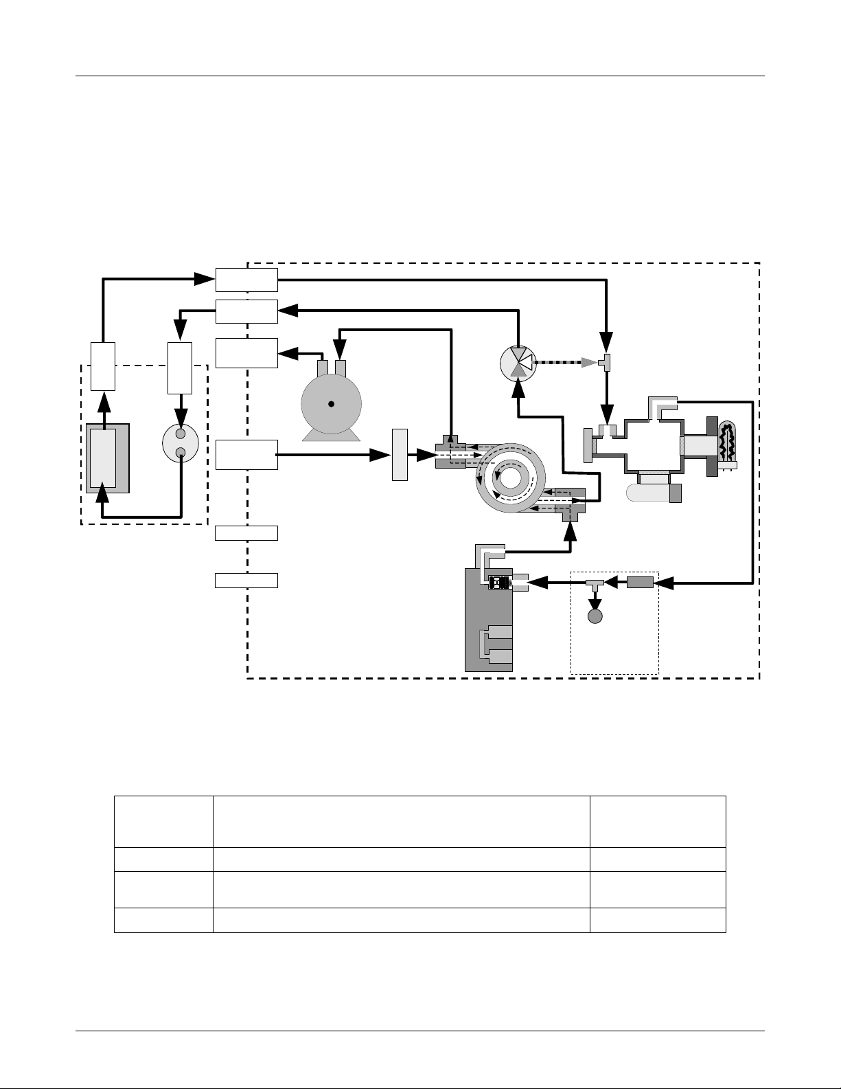
3.4. Internal Pneumatic Flow of the M102E & the
M501-TRS
Figure 3-3 shows the internal pneumatic flow of the M102E in its Standard configuration. For
information on instruments in which one of the various zero/span valve options refer to Figures 52 and 5-3.
TO
ANALYZER
2
SO
Æ
TRS
CONVERTER OVEN
SO
FROM
ANALYZER
r
2
Scrubbe
FROM
CONVERTER
TO
CONVERTER
EXHAUST GAS
OUTLET
SAMPLE GAS
INLET
INSTRUMENT
M102E
CHASSIS
KICKER EXHAUST
PUMP
SAMPLE FILTER
TO PUMP
TRS / SO
2
MODE
VALVE
HYDROCARBON
SCRUBBER
(KICKER)
Gas Flow in SO
3
1
2
phase
2
of multigas mode or
when i n SO
2
measurement mode
SAMPLE
CHAMBER
PMT
UV
LAMP
M501-TRS
ZERO AIR INLET
SPAN GAS INLET
VACUUM MANIFOLD
EXHAUST TO OUTE
LAYER OF KICKE
FLOW
CONTROL
ASSY
SAMPLE
PRESSURE
SENSOR
FLOW / PRESSURE
SENSOR PC
FLOW
SENSOR
Figure 3-3: Internal Pneumatic Diagram of the M102E Standard Con figuration.
Switching Valve Operating Modes
2
Bypasses M501-TRS
CONNECTION
(FIG. 5-2)
2 Æ 3
2 Æ 1
- -
GAS
MODE
TRS
SO2
TRS –SO2
Table 3-1: TRS – SO
CONDITION OF TRS –SO2 SWITCHING VALVE VALVE PORT
Open to SO
Switches between above two states every 10 minutes.
Scrubber and Molybdenum Converter
2
Open to directly to Sample Chamber.
8 05514 Rev A1
Page 15
M102E/M501 TRS GETTING STARTED
(Addendum to M101E Manual - P/N 04740 Rev A)
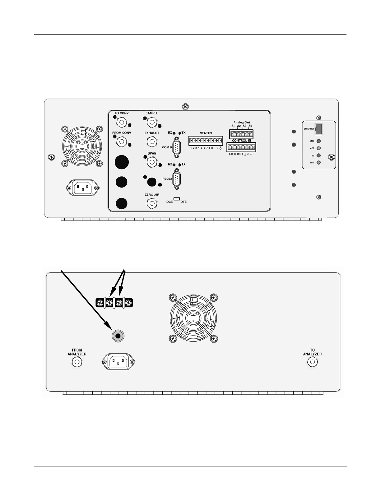
3.5. Rear Panel Layout for the M102E & M501-TRS
Figures 3-4 & 3-5 supersede Figure 3-2 of the M101E Manual - P/N 04740 Rev A.
5 Amp
Slow-Blow
Fuse
Figure 3-4: M102E Rear Panel Layout
Alarm Output
Connections
Figure 3-5: M501-TRS Rear Panel Layout
05514 Rev A1 9
Page 16
GETTING STARTED M102E/M501 TRS
(Addendum to M101E Manual - P/N 04740 Rev A)
3.6. Initial Setup
3.6.1. Electrical Connections:
The electrical connections for the M102E are the same as those described in Section 3.1.1 of the
M101E Manual - P/N 04740 Rev A except for the test channel analog output:
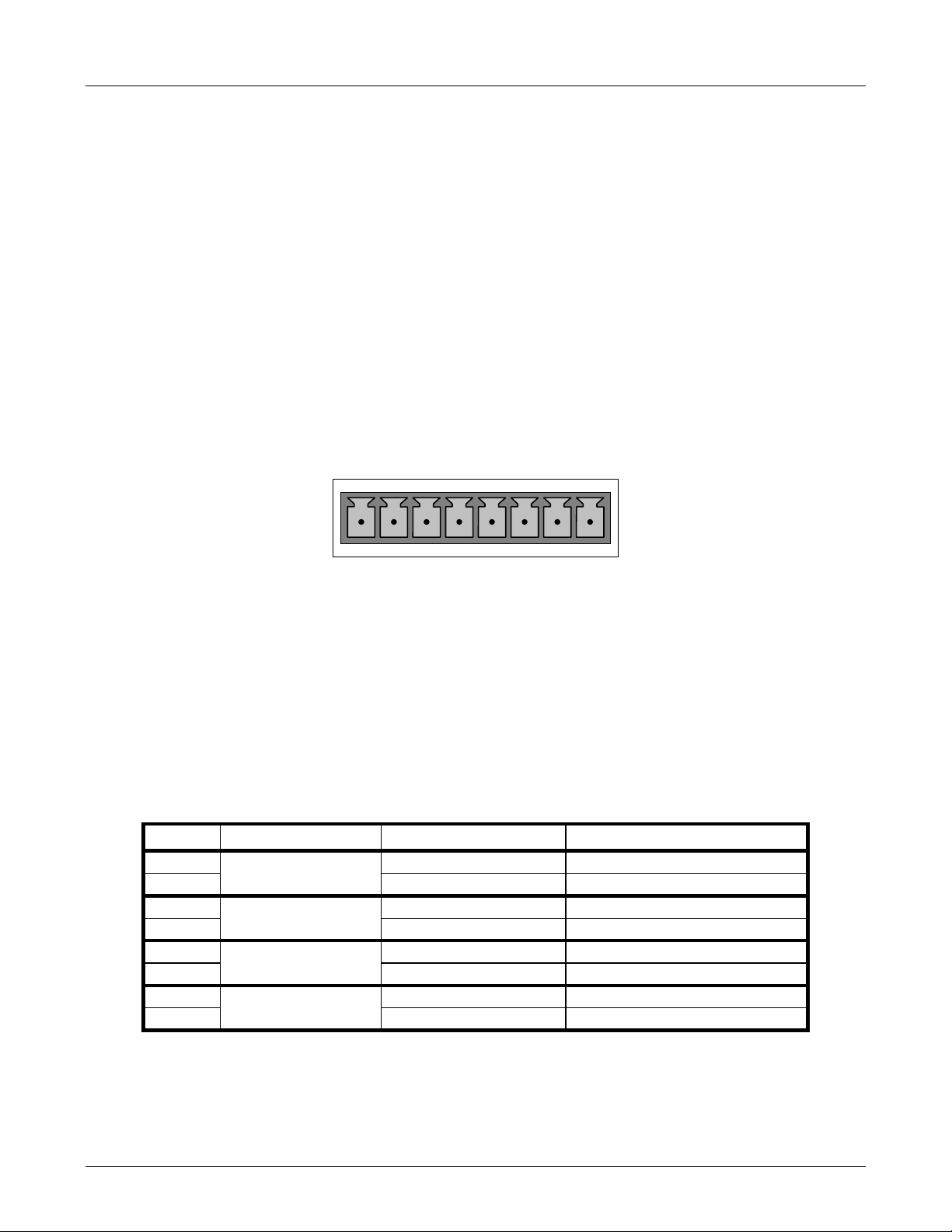
3.6.1.1. M102E Analog Output Connections
This section supercedes Section 3.1.1.1 of the M101E Manual - P/N 04740 Rev A.
Attach a strip chart recorder and/or data-logger to the appropriate contacts of the analog output
connecter on the rear panel of the analyzer.
A1 A2 A3 A4
+ - + - + - + -
ANALOG OUT
Figure 3-6: Analog Output Connector
The A1 and A2 channels output a signal that is proportional to the SO
concentration of the
2
sample gas.
The output, labeled A3 is special. It can be set by the user (see Section 6.9.10 of the M101E
Manual - P/N 04740 Rev A) to output any one of the parameters accessible through the <TST
TST> keys of the units sample display.
Pin-outs for the Analog Output connector at the rear panel of the instrument are:
Table 3–2: Analog output Pin Outs
PIN ANALOG OUTPUT VOLTAGE OUTPUT CURRENT LOOP OPTION
1 V Out I Out +
2
3 V Out I Out +
4
5 V Out I Out +
6
7 Not Available Not Available
8
A1
A2
A3
A4
Ground I Out -
Ground I Out -
Ground I Out -
Not Available Not Available
• The default analog output voltage setting of the M102E UV Fluorescence SO
Analyzer is 0
2
– 5 VDC with a range of 0 – 500 ppb.
10 05514 Rev A1
Page 17

M102E/M501 TRS GETTING STARTED
(Addendum to M101E Manual - P/N 04740 Rev A)
• TO change these settings, see Sections 6.9.4 and 6.7 of the M101E Manual - P/N 04740
Rev A respectively.
3.6.1.2. M501-TRS Alarm Output Connections
The rear panel of the M501-TRS includes a terminal strip by which connections can be made to
the converters internal temperature alarm for more information on this alarm see Section 6.5).
• Connect the input leads to your alarm-sensing device (e.g. datalogger) to the center two
pins of the alarm output connector (see Figure 3-5).
• Make sure the load does not exceed the rated capacity of the relay.
3.6.2. Pneumatic Connections:
This section supercedes the information contained in Section 3.1.2 of the M101E Manual
- P/N 04740 Rev A.
CAUTION
To prevent dust from getting into the analyzer, it was shipped with small plugs inserted
into each of the pneumatic fittings on the rear panel. Make sure that all dust plugs are
removed before attaching exhaust and supply gas lines.
Sample and calibration gases should only come into contact with PTFE (Teflon) or glass materials.
They should not come in contact with FEP or stainless steel materials.
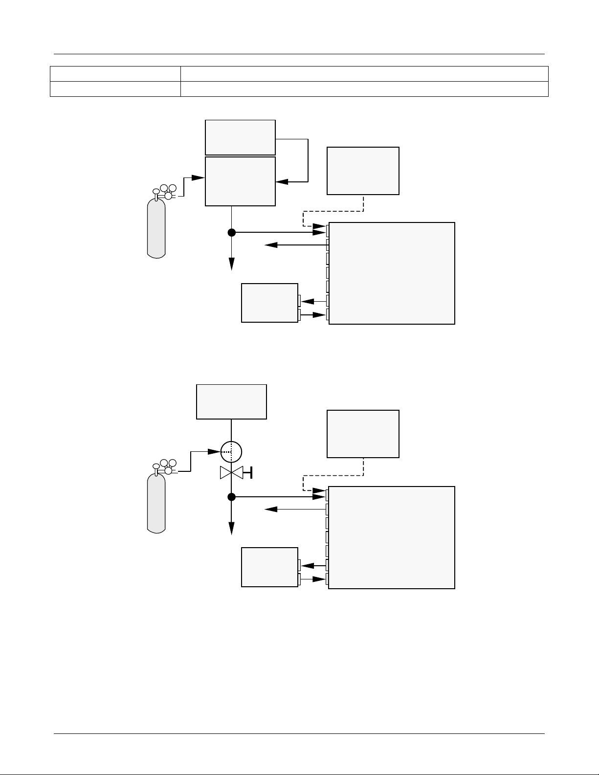
Figures 3-7 and 3-8 show the most common configurations for gas supply and exhaust lines to the
Model 102E Analyzer. Figures 3-9, 3-10 & 3-11 show the connections for units with valve options
installed.
Please refer to Figures 3-1 & 3.3 for the location of pneumatic connections at the rear panel of the
M102E and the M501-TRS.
Table 3-3: Inlet / Outlet Connector Nomenclature
M102E PNEMATIC CONNECTERS
REAR PANEL LABEL FUNCTION
SAMPLE
EXHAUST
SPAN
ZERO AIR
TO CONVERTER Sample gas leaves the M102E to be conditioned by the M501-TRS via this port.
FROM CONVERTER
Connects the sample gas to the analyzer. When operating the analyzer without
zero/span option, this is also the inlet for any calibration gases.
Exhausts the gas sampled by the analyzer. Connect to an outside area away
from people.
On units with zero/span/shutoff valve options installed, connect a gas line to
the source of calibrated span gas here.
On Units with zero/span valve or IZS option installed, this port connects the
zero air gas or the zero air cartridge to the analyzer.
Sample gas returns to the M102E after being conditioned by the M501-TRS via
this port.
M501-TRS PNEMATIC CONNECTERS
REAR PANEL LABEL FUNCTION
05514 Rev A1 11
Page 18
GETTING STARTED M102E/M501 TRS
(Addendum to M101E Manual - P/N 04740 Rev A)
FROM ANALYZER Sample gas enters the M501-TRS from the M102E via this port.
TO ANALYZER Sample gas leaves the M501-TRS to return to the M102E via this port.
Calibrated
span GAS
(At high
concentration)
MODEL 701
Zero Air
Generator
MODEL 700
Gas Dilutio n
Calibrator
(with Ozone
Bench Option)
VENT
M501-TRS
From Analyzer
To Analyzer
Source of
SAMPLE Gas
Removed
Calibration
Sample
Exhaust
Span
Zero Air
To Converter
From Converter
during
MODEL
102E
Figure 3-7: Pneumatic Connections–Basic Configuration–Using Gas Dilution Calibrator
MODEL 701
Zero Air
Calibrated
span GAS
Generator
Valve
Needle
valve to
control
flow
VENT
Source of
SAMPLE Gas
Removed
during
Calibration
Sample
Exhaust
Span
MODEL
102E
M501-TRS
From Analyzer
To Analyzer
Zero Air
To Converter
From Converter
Figure 3-8: Pneumatic Connections–Basic Configuration–Using Bottled Span Gas
8. Attach the 1/4" exhaust line to the exhaust port.
12 05514 Rev A1
Page 19

M102E/M501 TRS GETTING STARTED
(Addendum to M101E Manual - P/N 04740 Rev A)
CAUTION
The exhaust from the instrument needs to be vented outside the
immediate area or shelter surrounding the instrument and conform to all
safety requirements using a maximum of 10 meters of 1/4” PTFE tubing.
9. Attach the sample line to the sample inlet port. Ideally, the pressure of the sample gas should
be equal to ambient atmospheric pressure.
NOTE
Maximum pressure of any gas at the sample inlet should not exceed 1.5 in-Hg above
ambient pressure and ideally should equal ambient atmospheric pressure.
In applications where the sample gas is received from a pressurized manifold, a vent
must be provided to equalize the sample gas with ambient atmospheric pressure before
it enters the analyzer. The vented gas needs to be routed outsi de the immediate area or
shelter surrounding the instrument.
10. Attach zero air and span gas supply lines as appropriate (see Figures 3-5 & 3.5).
• Zero air and span gas inlets should supply their respective gases in excess of the 700
3
/min demand of the analyzer. Supply and vent lines should be of sufficient length and
cc
diameter to prevent back diffusion and pressure effects.
• For this type of analyzer, zero air and span gas are defined as follows:
SPAN GAS
• While it is possible to calibrate the M102E using SO
the analyzers gas measurement mode to SO
, Teledyne Instruments recommends that H2S
2
as the span calibration gas by setting
2
be used and that calibration operations be carried out with the analyzer’s TRS gas
measurement mode selected. Please note that verifying converter efficiency requires that
the instrument be calibrated on both TRS and SO
between the TRS and SO
• It is recommended that the H
modes.
2
S span gas be equal to 90% of the analyzer’s selected
2
, and the slope factors compared
2
reporting range.
• O2 is a quenching agent in fluorescent Sulfur analyzers. If the balance gas is pure
nitrogen, then false positive readings will result, both at zero and span. Therefore the user
should either use cylinders with zero air as the balance gas, or should use higher
concentration cylinders with an N2 balance, and dilute further with zero air using a
calibrator, such as the TAPI M700.
EXAMPLE: If the selected reporting rang is 0 ppb Æ 500 ppb, an appropriate span gas
concentration would be 450 ppb H
Cylinders of calibrated H
S gas traceable to NIST-Standard Reference Material specifications
2
S.
2
(also referred to as SRM’s or EPA protocol calibration gases) are commercially available. Table
3-4 lists specific NIST-SRM reference numbers for various concentrations of H
2
S.
05514 Rev A1 13
Page 20

GETTING STARTED M102E/M501 TRS
(Addendum to M101E Manual - P/N 04740 Rev A)
Table 3-4: NIST-SRM's Available for Traceability of H2S & SO2 Calibration Gases
NIST-SRM4 TYPE
2730
2731
Hydrogen sulfide in N
Hydrogen sulfide in N2
2
NOMINAL
CONCENTRATION
5000 ppb
20 ppm
ZERO AIR
• A gas that is similar in chemical composition to the earth’s atmosphere but without the
gas(es) being measured by the analyzer, in this case total reduced sulfur (TRS). While
TRS typically includes Hydrogen sulfide (H
(CH
and Methyl mercaptan (MeSH), CH4S many other gases fall into this category as
3)2S2
S), Dimethyl sulfide (CH3)2 , Dimethyl disulfide
2
well. In addition other interferent gases may be present in ambient air as well.
To ensure that high quality zero air is available a zero air generator such as the Teledyne
Instruments Model 701 should be used.
• If your analyzer is equipped with an IZS option, it is capable of creating zero air that is
adequate for performing informal calibration checks, but a zero air generator such as the
Teledyne Instruments Model 701 is still recommended for performing formal calibration
operations.
11. Once the appropriate pneumatic connections have been made, check all pneumatic fittings for
leaks using a procedure similar to that defined in Section 11.5.1 of the M101E Manual - P/N
04740 Rev A.
3.6.2.1. Connections with Internal Valve Options Installed
If your analyzer is equiped with either the zero/span valve option (Option 50) or the internal
zero/span option (Option 51), the pneumatic connections should be made as shown in
Figures 3-9; 3-10 & 3-11:
14 05514 Rev A1
Page 21
M102E/M501 TRS GETTING STARTED
p
p
r
r
(Addendum to M101E Manual - P/N 04740 Rev A)
Zero/Span Valves – Option 50
VENT if input is pressurized
le
Sam
Exhaust
S
an
Zero Air
To Converter
From Converter
MODEL
102E
MODEL 700
Gas Dilution Calibrator
(with O3 generator option)
Calibrated
SO
or H2S
2
gas
(At high
concentration)
VENT
MODEL 701
Zero Air
Generator
Source of
SAMPLE Gas
External Zero
Air Scrubber
M501-TRS
Filter
To Analyze
From Analyze
Figure 3-9: Basic Pneumatic Connections for Units with Zero/Span Valve Option
05514 Rev A1 15
Page 22
GETTING STARTED M102E/M501 TRS
p
r
r
p
(
)
p
r
(Addendum to M101E Manual - P/N 04740 Rev A)
MODEL 700
Gas Dilution Calibrator
(with O3 generator option)
Calibrated
H2S gas
(At high
concentration)
VENT
MODEL 701
Zero Air
Generator
Source of
SAMPLE Gas
External Zero
Air Scrubber
M501-TRS
To Analyze
From Analyze
Filter
VENT if input is pressurized
le
Sam
Exhaust
MODEL
102E
Zero Air
To Converter
From Converter
Figure 3-10: Pneumatic Connections for Formal Calibration of Units with an IZS Valve
Option
Source of
SAMPLE Gas
VENT if input is pressurized
Sam
Ambient
Air
M501-TRS
From Analyze
To Analyzer
le
Exhaust
S
an
Zero Air
To Converter
From Converter
MODEL
102E
Scrubber
Figure 3-11: Pneumatic Connections for Informal Calibration Checks of Units with IZS
Valve Option
NOTE
Gas flow must be maintained at all times for units with IZS Options installed. The IZS
option requires a permeation tube ( customer supplied ) which emits H2S. Insufficient
gas flow can build up H2S to levels that will damage the instrument.
Remove the permeation device when taking the analyzer out of operation.
16 05514 Rev A1
Page 23
M102E/M501 TRS GETTING STARTED
g
(Addendum to M101E Manual - P/N 04740 Rev A)
3.7. Initial Operation
3.7.1. Startup / Warm Up of the M102E
Startup procedures and warm up behavior of the M102E are identical to those described in
Sections 3.2.1 and 3.2.2 of the M101E Manual - P/N 04740 Rev A.
Possible Warning Messages at Start-Up
Warning messages for the M102E is the same as the list of warning messages included in
appendix A—3 of the M101E Manual - P/N 04740 Rev A with the exception that there is no CONV
TEMP WARNING (converter Temperature Warning).
3.7.2. Functional Check of the M102E
To performing an initial functional check of the M102E follow the steps contained in Section 3.2.4
of the M101E Manual - P/N 04740 Rev A.
Test Functions
The following diagram supercedes the one found in Step 2 of Section 3.2.4 of the M101E Manual P/N 04740 Rev A.
SAMPLE RANGE = 500.0 PPB TRS = X.X
< TST TST > CAL SETUP
RANGE
TRS STB
PRES
Toggle <TST TST> keys to
scroll throu
1
Only appears if IZS option is
installed.
2
Only appears if analog output A4
is actively reporting a test function.
3
Shown as they appear when analyzer
is in TRS mode. In SO
h list of functions
mode appear as SO2 STB, SO2 OFFS &
2
SAMP FL
PMT
NORM PMT
UV LAMP
LAMP RATIO
STR. LGT
DARK PMT
DARK LAMP
TRS SLOPE
TRS OFFS
HVPS
RCELL TEMP
BOX TEMP
PMT TEMP
IZS TEMP
TEST
TIME
SO2 SLOPE. In multigas mode, both versions appear.
3
Refer to Section
6.2.1 of the M101E
3
Manual - P/N 04740
3
Rev A for definitions
of these test
functions.
1
2
05514 Rev A1 17
Page 24
GETTING STARTED M102E/M501 TRS
(Addendum to M101E Manual - P/N 04740 Rev A)
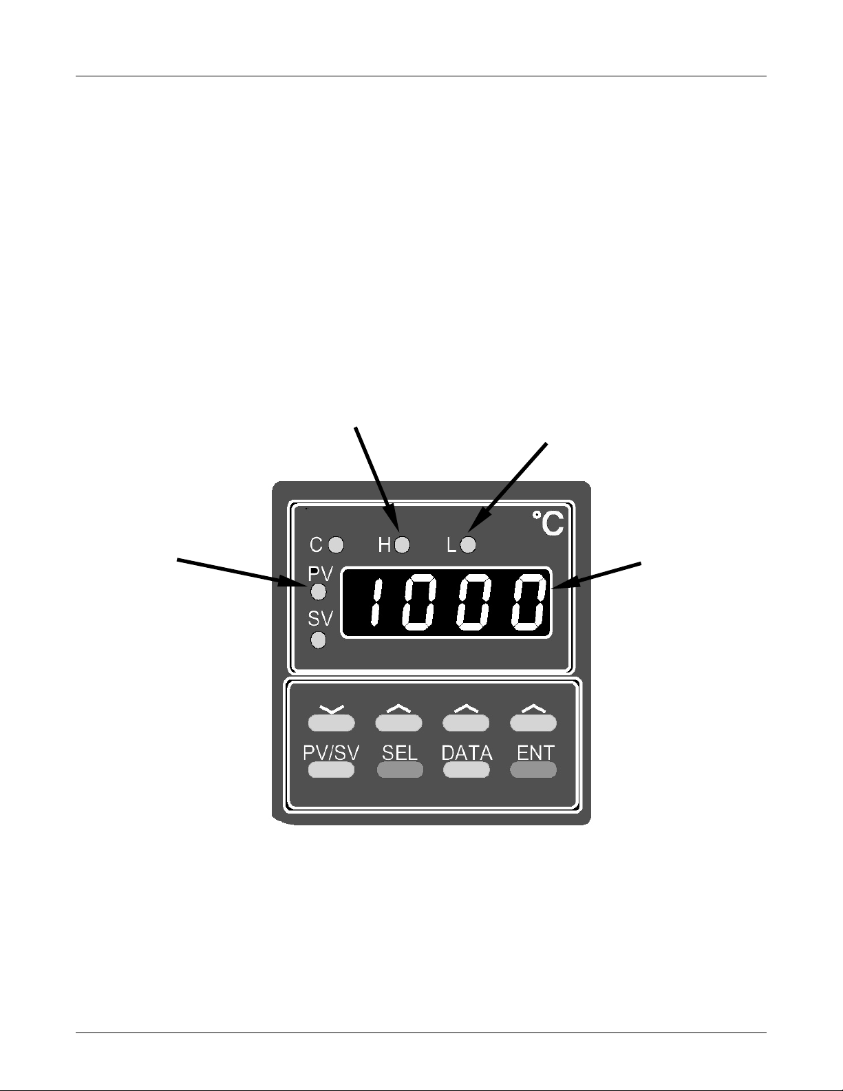
3.7.3. Startup / Warm Up of the M501-TRS
After electrical and pneumatic connections are made, turn on the instrument and pump power.
The exhaust fan should start.
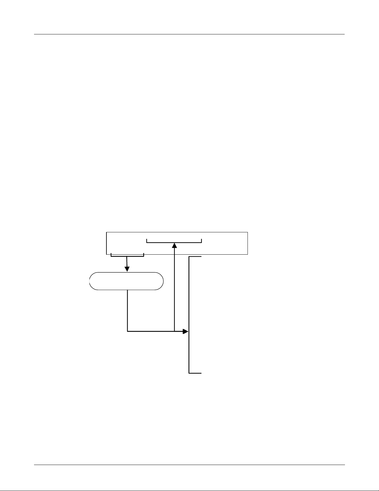
The M501-TRS’ temperature controller is preprogrammed at the factory so no special setup
operation is required. The temperature controller (see Figure 3-12) should immediately come on
in operation mode: the current temperature of the converter oven should the display immediately
appear in the display area and the process
It may take as much as 30 minutes for the oven to reach its nominal operating temperature.
During that initial warm up period the high and low alarms and the M501-TRS single alarm output
are disabled. Both the internal alarms and the alarm output will be automatically enabled once
the converter oven temperature rises above the lower alarm limit.
value (PV) LED should be lit.
Process Variable
LED
High Alarm LED
Low Alarm LED
Display area
Figure 3-12: M501-TRS Temperature Controller Startup
18 05514 Rev A1
Page 25

M102E/M501 TRS GETTING STARTED
(Addendum to M101E Manual - P/N 04740 Rev A)
3.8. Initial Calibration
Initial calibration of the M102E should be performed with:
• Zero air supplied by a zero air generator such as the Teledyne Instruments’ M701;
• Calibrated H
• With external pneumatic connections as described in Figures 3-7 through 3-11 of this
addendum, and;
• Using the information and procedure included in Section 3.3 of the M101E Manual - P/N
04740 Rev A.
No initial calibration of the M501-TRS temperature controller is required.
Once you have completed the above set-up procedures, please fill out the quality
questionnaire that was shipped with your unit and return it to Teledyne Instruments.
This information is vital to our efforts in continuously improving our service and our
S span gas of the appropriate concentration:
2
NOTE
products. Thank you.
User Notes:
05514 Rev A1 19
Page 26

Page 27

M102E/M501 TRS OPTIONAL HARDWARE AND SOFTWARE
(Addendum to M101E Manual - P/N 04740 Rev A)
4. OPTIONAL HARDWARE AND SOFTWARE
This section includes descriptions of the hardware and software options available for the Model
102E analyzer and M501-TRS converter that are different from or not included in Chapter 5 of the
M101E Manual - P/N 04740 Rev A. For all other available options see that document.
For assistance with ordering these options please contact the sales department of Teledyne
Instruments at:
TOLL-FREE: 800-324-5190
TEL: +1 858-657-9800
FAX: +1 858-657-9816
E-MAIL: apisales@teledyne.com
WEB SITE: http://www.teledyne-api.com
4.1. Rack Mount Kits (Options 20a, 20b, 21, 22 & 81)
The following table supercedes the one included in Section 5.1 of the M101E Manual - P/N 04740
Rev A.
OPTION NUMBER DESCRIPTION
OPT 20A Rack mount brackets with 26 in. chassis slides.
OPT 20B Rack mount brackets with 24 in. chassis slides.
OPT 21 Rack mount brackets only
OPT 22 Rack Mount for M501-TRS
OPT 81 Rack Mount for M501-TRS with slides
4.2. Calibration Valves Options
4.2.1. Zero/Span Valves (Option 50) & Internal Zero/Span Gas
Generator (Option 51)
The description of the construction and operation for the zero span and IZS valve options for the
M102E TRS is identical to that information contained in Section 5.4of the M101E Manual - P/N
04740 Rev A.
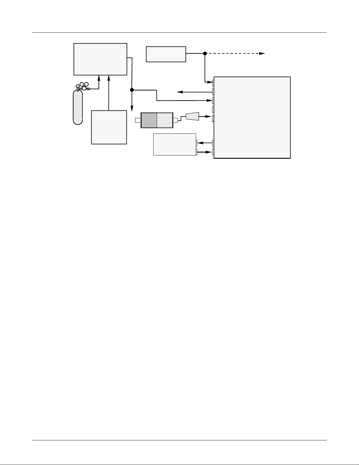
The internal pneumatic flow or the M102E with either of these options installed is however
different. See:
• Figure 4-1 for an illustration of the M102E internal gas flow with the zero/span valves
(option 50), and;
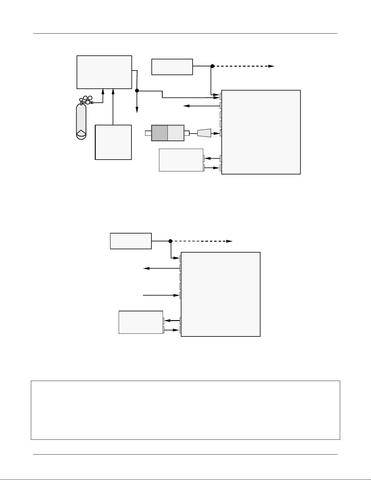
• Figure 4-2 for an illustration of the M102E internal gas flow with the IZS valve (option 1).
05514 Rev A1 21
Page 28

OPTIONAL HARDWARE AND SOFTWARE M102E/M501 TRS
V
R
R
A
(Addendum to M101E Manual - P/N 04740 Rev A)
TO
ANALYZER
2
TRS Æ SO
CONVERTER OVEN
2
SO
FROM
ANALYZER
Scrubber
FROM
CONVERTER
CONVERTER
EXHAUST GAS
OUTLET
M501-TRS
SAMPLE GAS
INLET
ZERO AIR INLET
SPAN GAS INLET
TO
PUMP
ZERO/SPAN
VALVE
3 2
1
3
1
SAMPLE FILTER
2
SAMPLE/CAL
KICKER EXHAUST
TO PUMP
ALVE
TRS / SO
2
MODE
VALVE
HYDROCARBON
SCRUBBER
(KICKER)
VACUUM MANIFOLD
Gas Flow in SO
of multigas mode or
3
1
when i n SO
2
measurement mode
EXHAUST TO OUTE
LAYER OF KICKE
FLOW
CONTROL
ASSY
phase
2
2
SAMPLE
PRESSURE
SENSOR
FLOW / PRESSURE
SENSOR PC
SAMPLE
CHAMBER
PMT
FLOW
SENSOR
M102E
INSTRUMENT
CHASSIS
UV
LAMP
Figure 4-1: Internal Pneumatic Diagram of the M102E With Z/S Option Installed.
The following table describes the state of each valve during the analyzer’s various operational
modes.
Table 4-1: Zero/Span Valve Operating States
MODE VALVE CONDITION VALVE PORT
CONNECTION
(FIG. 5-2)
SAMPLE
Zero/Span Open to ZERO AIR inlet
Sample/Cal Open to zero/span inlet
Sample/Cal Open to SAMPLE inlet
ZERO CAL
Zero/Span Open to ZERO AIR inlet
Sample/Cal Open to zero/span inlet
SPAN CAL
Zero/Span Open to SPAN GAS inlet
3 Æ 2
3 Æ 2
1 Æ 2
3 Æ 2
1 Æ 2
1 Æ 2
22 05514 Rev A1
Page 29

M102E/M501 TRS OPTIONAL HARDWARE AND SOFTWARE
A
R
V
(Addendum to M101E Manual - P/N 04740 Rev A)
`
TO
ANALYZER
2
TRS Æ SO
CONVERTER OVEN
ZERO AIR INLET
2
SO
FROM
TO
OUTLET
INLET
ZERO/SPAN
VALVE
3 2
PUMP
3
1
1
IZS
Permeation Tube
SO
Source
2
2
SAMPLE/CAL
SAMPLE
FILTER
ALVE
KICKER EXHAUST
TO PUMP
TRS / SO
VALVE
HYDROCARBON
SCRUBBER
(KICKER)
EXHAUST TO OUTER LAYE
MODE
VACUUM MANIFOLD
INSTRUMENT
when i n SO
phase
2
2
SAMPLE
PRESSURE
SENSOR
FLOW / PRESSURE
SENSOR PC
SAMPLE
CHAMBER
PMT
FLOW
SENSOR
Gas Flow in SO
of multigas mode or
3
2
1
2
measurement mode
OF KICKER
CRITICAL
FLOW
ORIFICE
CRITICAL
FLOW
ORIFICE
CONVERTER
CONVERTER
EXHAUST GAS
FROM
ANALYZER
r
Scrubbe
SAMPLE GAS
M501-TRS
ZERO AIR
SCRUBBER
M102E
CHASSIS
UV
LAMP
Figure 4-2: Internal Pneumatic Diagram of the M102E with IZS Options Installed.
The following table describes the state of each valve during the analyzer’s various operational
modes.
Table 4-2: IZS Valve Operating States
MODE VALVE CONDITION VALVE PORT
CONNECTIONS
SAMPLE
ZERO CAL
SPAN CAL
Sample/Cal Open to SAMPLE inlet
Zero/Span Open to ZERO AIR inlet
Sample/Cal Open to zero/span valve
Zero/Span Open to ZERO AIR inlet
Sample/Cal Open to zero/span valve
Zero/Span Open to SPAN GAS inlet
3 Æ 2
3 Æ 2
1 Æ 2
3 Æ 2
1 Æ 2
1 Æ 2
05514 Rev A1 23
Page 30

OPTIONAL HARDWARE AND SOFTWARE M102E/M501 TRS
(Addendum to M101E Manual - P/N 04740 Rev A)
4.3. Additional Manuals
4.3.1. Printed Manuals (P/N 049880000)
Additional printed copies of this addendum are available from Teledyne Instruments
4.3.2. Addendum on CD (Part number 049880200)
This addendum is also available on CD. The electronic document is stored in Adobe Systems Inc.
Portable Document Format (PDF) and is viewable with Adobe Acrobat Reader
downloadable for free at http://
The CD version of the addendum has many advantages:
Fully searchable text.
Hypertext links for figures, tables, table of contents and embedded references for quick access of
individual addendum portions.
A list of thumbnails, chapters and sections displayed at the left of the text.
Internet links embedded in the addendum will take you to the corresponding web site (requires an
internet connection).
www.adobe.com/
®
software,
User Notes:
24 05514 Rev A1
Page 31

M102E/M501 TRS M102E OPERATING INSTRUCTIONS
d
d
(Addendum to M101E Manual - P/N 04740 Rev A)
5. M102E OPERATING INSTRUCTIONS
NOTE
For the most part the operation instruction for the M102Eare the same as those
described in Chapter 6 of the M101E Manual - P/N 04740 Rev A with the exception that
the terms “TRS” & “total reduced sulfur” should be substituted for the t erms “H2S” &
“hydrogen sulfide” unless otherwise stated in this addendum.
5.1.1. M102E Analog Output Signals
The information contained in Section 6.7.1 of the M101E Manual - P/N 04740 Rev A is correct
except that the test channel output is located on analog output A3 rather than A4 .
ANALOG OUT
SO2 concentration
A1 A2 A3 A4
+ - + - + - + -
LOW range when
DUAL mode is selecte
outputs
Test Channel
HIGH range when
DUAL mode is selecte
Not Used
Figure 5-1: Analog Output Connector Key
NOTE
On analyzers with the SO2-TRS multigas gas measurement option available, the outputs
of A1 and A2 correspond to:
Output SO
2 SO2
– TRS TRS
Channel Mode Mode Mode
A1 ÅÆ SO2 ÅÆ SO2 ÅÆ TRS
A2 ÅÆ SO2 ÅÆ TRS ÅÆ TRS
As the instrument switches from TRS mode to SO2 mode and back, only the reporting
range and analog output associated with the gas currently being measured will be
active. The reporting range and analog output for the gas not being measured will
continue to report the last valid reading.
05514 Rev A1 25
Page 32

M102E OPERATING INSTRUCTIONS M102E/M501 TRS
(Addendum to M101E Manual - P/N 04740 Rev A)
The output, labeled A3 is special. It can be set by the user (see Section 6.9.10 of the M101E
Manual - P/N 04740 Rev A) to output many of the parameters accessible through the <TST TST >
keys of the units Sample Display.
Output A4 is not available on the Model 102E Analyzer.
5.1.2. Setting the M102E Gas Measurement Mode
Setting the gas measurement mode on the M102E is identical to the method described in Sections
6.8.1 of the M101E Manual - P/N 04740 Rev A except that the available measurement ranges are:
Table 5-1 M102E gas Measurement Modes
GAS
MODE
TRS
SO2
TRS –SO2
The sample gas stream is stripped of any ambient SO
chemical scrubber, then passed through a catalytic converter that
changes the TRS present into SO
UV Fluorescence method
The sample gas stream bypasses the SO
converter allowing the only ambient SO2 to be measured.
The switching valve alternates the gas stream between the two paths
at regular intervals allowing the instrument to measure both gases.
DESCRIPTION
which is then measured using the
2
Scrubber and catalytic
2
by a special
2
5.2. SETUP – DIAG: Using the Diagnostics Functions
5.2.1. M102E Analog I/O Configuration
The following table supercedes Table 6-11 of the M101E Manual - P/N 04740 Rev A
Table 5-2: Analog Output Pin Assignments
PIN ANALOG
OUTPUT
1 V Out I Out +
2
3 V Out I Out +
4
5 V Out not available
6
7-8
A1
A2
A3
A3
VOLTAGE
SIGNAL
Ground I Out -
Ground I Out -
Ground not available
Not Used Not Used
CURRENT
SIGNAL
See Figure 3-4 for a the location of the analog output connector on the instruments rear panel.
26 05514 Rev A1
Page 33

M102E/M501 TRS M102E OPERATING INSTRUCTIONS
(Addendum to M101E Manual - P/N 04740 Rev A)
5.2.2. M102E Test Channel Output
The following table supercedes Table 6-14 of the M101E Manual - P/N 04740 Rev A
Table 5-3: Test Parameters Available for Analog Output A4
TEST CHANNEL TEST PARAMETER RANGE 1
NONE Test channel is turned off
PMT READING 0-5000 mV
UV READING 0-5000 mV
SAMPLE PRESSURE 0-40 in-Hg-A
SAMPLE FLOW 0-1000 cm³/min
RCELL TEMP 0-70° C
CHASSIS TEMP 0-70° C
IZS TEMP 0-70° C
PMT TEMP 0-50° C
CHASSIS TEMP 0-70° C
HVPS VOLTAGE 0-5000 V
1
This refers to the voltage range of the parameter and
not the output signal of the test channel.
Once a TEST function is selected, the instrument begins to report a signal on the A36 output and
adds TEST= to the list of test functions viewable on the display (just before the TIME display).
5.3. SETUP – COMM: Setting Up the M102E’s
Communication Ports
5.3.1. M102E ID Code
The default ID code for all M102E analyzers is 102.
To edit the instrument’s ID code, see Section 6.10.1 of the M101E Manual - P/N 04740 Rev A.
5.3.2. M102E Ethernet Host Name
The default name for all Teledyne Instruments Model 102E analyzers is M102E.
To change the Ethernet Host Name see Section 6.10.6.4 of the M101E Manual - P/N 04740 Rev A.
05514 Rev A1 27
Page 34

M102E OPERATING INSTRUCTIONS M102E/M501 TRS
(Addendum to M101E Manual - P/N 04740 Rev A)
5.4. Remote Operation of the Analyzer
5.4.1. Control Inputs
The description of the control inputs in Section 6.12.1.2 of the M101E Manual - P/N 04740 Rev A
in correctly shows an external low span cal input. This is not correct. Neither the M102E nor the
M102E has an external low span cal input.
The following table and figures supercede Table 6-23 and Figures 6-18 & 6-19 of the M101E
Manual - P/N 04740 Rev A respectively.
Table 5-4: M102E Control Input Pin Assignments
INPUT STATUS CONDITION WHEN ENABLED
A External Zero Cal
B External Span Cal
C, D, E, & F Unused
Digital Ground Provided to ground an external device (e.g., recorder).
Zero calibration mode is activated. The mode field of the
display will read ZERO CAL R.
Span calibration mode is activated. The mode field of the
display will read SPAN CAL R.
U
+
DC Power For
Input Pull Ups
Internal +5v
Supply
Input for +5 VDC required to activate inputs A - F. This voltage
can be taken from an external source or from the “+” pin.
Internal source of +5V which can be used to activate inputs
when connected to pin U.
A B C D E F U
ZERO
SPAN
CONTROL IN
+
Figure 5-2: Control Inputs with local 5 V power supply
28 05514 Rev A1
Page 35

M102E/M501 TRS M102E OPERATING INSTRUCTIONS
(Addendum to M101E Manual - P/N 04740 Rev A)
CONTROL IN
A B C D E F U +
ZERO
SPAN
LOW SPAN
5 VDC Power
-
+
Supply
Figure 5-3: Control Inputs with external 5 V power supply
5.4.2. Using the M102E with a Hessen Protocol Network
5.4.2.1. M102E Hessen Protocol Gas ID List.
The default Hessen Gas Id’s for all M102E analyzers are:
Table 5-5: M102E Default Hessen Gas ID’s
Gas Type Hessen Gas ID
SO2 111
TRS 112
To edit the instrument’s ID code, see Section 6.12.4.6 of the M101E Manual - P/N 04740 Rev A.
05514 Rev A1 29
Page 36

M102E OPERATING INSTRUCTIONS M102E/M501 TRS
(Addendum to M101E Manual - P/N 04740 Rev A)
5.4.2.2. Setting Hessen Protocol Status Flags
The following table supercedes Table 6-29 of the M101E Manual - P/N 04740 Rev A/
Table 5-6: Default Hessen Status Bit Assignments
WARNING FLAGS
SAMPLE FLOW WARNING 0001
PMT DET WARNING 0002
UV LAMP WARNING 0002
HVPS WARNING 0004
DARK CAL WARNING 0008
RCELL TEMP WARNING 0010
IZS TEMP WARNING 0020
PMT TEMP WARNING 0040
CONV TEMP WARNING 1000
OPERATIONAL FLAGS
In Manual Calibration Mode 0200
In Zero Calibration Mode 0400
In Span Calibration Mode 0800
UNITS OF MEASURE FLAGS
UGM 0000
MGM 2000
PPB 4000
PPM 6000
SPARE/UNUSED BITS 0080, 0100, 1000,
UNASSIGNED FLAGS
Box Temp Warning Front Panel Warning
Sample Press Warning Analog Cal Warning
System Reset Cannot Dyn Zero
Rear Board Not Detected Cannot Dyn Span
Relay Board Warning Invalid Conc
STATUS FLAG NAME DEFAULT BIT
ASSIGNMENT
8000
User Notes:
30 05514 Rev A1
Page 37

M102E/M501 TRS M501-TRS OPERATING INSTRUCTIONS
V
(Addendum to M101E Manual - P/N 04740 Rev A)
6. M501-TRS OPERATING INSTRUCTIONS
CAUTION !
DO NOT OPERATE WITHOUT THE COVER OF THE M501TS CONVERTER
INSTALLED.
OVEN TEMPERATURE WILL NOT REGULATE PROPERLY WITHOUT THE
COVER IN PLACE.
NOTE:
Changing the Converter temperature from the value preprogrammed at the factory may
have undesirable effects of TRS converters efficiency.
Do not change this value unless absolutely necessary or unless directed to do so by
Teledyne Instruments customer service.
6.1. Basic M501-TRS Controls
Control
Indicator
Process
alue (PV)
Indicator
High Alarm
indicator
Low Alarm
indicator
Main Display
100’s Digit
UP key
Set
Value (SV)
Indicator
DOWN key
PV/SV
Mode
Key
Program SELECT
Key
DATA key
10’s Digit
UP key
1’s Digit
UP key
ENTER key
Figure 6–1: M501-TRS Temperature Controls
05514 Rev A1 31
Page 38

M501-TRS OPERATING INSTRUCTIONS M102E/M501 TRS
(Addendum to M101E Manual - P/N 04740 Rev A)
Table 6-1: M501-TRS Temperature Controls and Definitions
NAME FUNCTION
Main Display A 4-digit, 7 segment LED display on which the current value of the PV and the
SV as well as error codes and programming parameters and data are all
displayed.
Process value
(PV) indicator
PV/SV Mode
key
Set value
Indicator
Program
SELECT key
DATA key Displays the current setting assigned to the parameter selected with the
ENTER key Once the value of a parameter is changed, press this key to store the new value
1’s Digit UP
key
10’s Digit UP
key
100’s Digit UP
key
DOWN key Decrements the numerical value by one digit of which ever display position (1,
Control
Indicator
High Alarm
Indicator
Low Alarm
Indicator
When lit indicates that the value on the main display is the process value (SV).
Toggling this key switches the main display between the PV and the SV.
When lit indicates that the value on the main display is the set value (SV).
To access the Primary Parameter Menu - Press and release this key once
To access the Secondary Parameter Menu - Press and hold this key for 3 sec.,
then release.
Repeatedly pressing this key scrolls though the list of available parameter for
whatever menu is selected in ascending order.
SEL/DOWN/100’s UP keys
in memory.
Press once to select the 1’s digit of the display when in numeric mode. Hold the
key down to continuously increment the 1’s digit. When “9” is reached the digit
loops back to “0”
Same as 1’s Digit UP key but for 10’s digit.
Same as 1’s Digit UP key but for 10o’s digit. When “9” is reached the digit loops
back to “0” and the 1000’s digit is incremented by one.
10, or 100) selected with by pressing the appropriate UP key.
In Program mode, where various parameters are displayed, repeatedly pressing
this key scrolls though the list of available parameter in descending order
Lit when the controller is actively controlling the heater temperature.
Lit when the PV equals or exceeds the upper alarm limit.
Lit when the PV equals or falls below the lower alarm limit.
6.2. To Display The Current Temperature:
If the Process value (PV) indicator is lit. the process value is currently being displayed.
If it is not lit Press the PV/SV mode key.
32 05514 Rev A1
Page 39

M102E/M501 TRS M501-TRS OPERATING INSTRUCTIONS
(Addendum to M101E Manual - P/N 04740 Rev A)
6.3. To Manually Adjust the Converter Oven
Temperature:
CAUTION !
DO NOT SET THE TEMPERATURE HIGHER THAN 1050OC
1. Set the main display to show the current value of the set variable by pressing the PV/SV mode
key.
2. To set each digit:
a. Press the up-arrow under that digit once. The digit will flash.
b. to increment that digit, press and hold the digit until the appropriate number is displayed.
c. To decrement that digit press and hold the DOWN key until the appropriate number is
displayed.
d. To increment/decrement the 1000’s digit it is necessary to adjust increment/decrement the
100’s digit up and down. Each time the 100’s digit passes “0” the 1000s digit will
increment or decrement correspondingly.
3. Once the desired value is reached, press the ENT key to store the new set value
4. Return the main display to process mode by pressing the PV/SV mode key once
EXAMPLE to change the set value from 950 to equal 1010.
ACTION RESULT
Press the PV/SV mode key The SV indicator will lit up and the display will
show 950.
Press the 10’s UP key once The 10’s digit will begin to blink
Press the DOWN key The 10’s digit will decrement from “5”. Release
the DOWN key when the 10’s digit reads “1”.
Press the 100’s UP Key once The 100’s digit will begin to blink
Press and hold the 100’s UP key The 100’s digit will increment from “9”. When it
passes “0” the 1000’s digit will increment to “1”.
Release the 100’s UP key.
-- The Display should now read “1010”
Press the ENTER key The new set value is recorded
Press the PV/SV mode key The current level of the process value will be
displayed.
05514 Rev A1 33
Page 40

M501-TRS OPERATING INSTRUCTIONS M102E/M501 TRS
(Addendum to M101E Manual - P/N 04740 Rev A)
6.4. Autotune the Temperature Controller:
The M501-TRS controller includes an auto tune feature which allows the controller to find and set
optimum values for various process control parameters so that the controller can establish and
maintain the converter oven at the temperature set value in the most stable and efficient manner.
NOTE
Before initiating the autotune feature make sure that the converter temperature oven
has reached a stable, constant temperature.
6.4.1. Initiating the Autotune Process:
1. Press the SELECT key once. The main display will show
2. Use the SELECT , DOWN or 100’s UP key to scroll through the primary menu parameters until
the display shows
3. Press the DATA key once. The display will show
4. Press the 1’s UP key once. The display will show
(AT =Autotune).
(zero = Off).
(1 = autotune based on set point value).
5. Press the ENTER key to begin the autotune process. A blinking decimal point will appear at the
bottom right-hand corner of the main display.
6. Wait until the blinking light stops. This may take up to 30 minutes.
7. The autotune process is finished. The autotune parameter value will automatically reset to
zero (off).
8. Press the PV/SV mode key to return to operational mode.
Note
The P-I-D parameters calculated by autotuning will be retained even if the power is lost.
However, if the power is turned off during the auto-tuning process, you must restart
autotuning.
34 05514 Rev A1
Page 41

M102E/M501 TRS M501-TRS OPERATING INSTRUCTIONS
(Addendum to M101E Manual - P/N 04740 Rev A)
6.4.2. Aborting the Autotune Process:
1. Press the DATA key once. The display will show (1).
2. Press the 1’s UP key once. The
3. Press the DOWN key once. The display will show
4. Press the ENTER key once.
5. Press the PV/SV mode key to return to operational mode.
Auto-tuning MUST to be repeated if there is a significant change in the set value.
If the temperature begins to oscillate excessively around the set value, it may be
necessary to repeat the autotune procedure.
will begin blinking
(zero).
Note
6.5. M501TRS Alarm Relay Adjustment
To set the High and Low Alarm points:
6. Press the SELECT key once. The main display will show
7. Use the SELECT , DOWN or 100’s UP key to scroll through the primary menu parameters until
the display shows either
(AL = Alarm Low) or
8. Press the DATA key once. The current value of the alarm limit will be displayed.
9. To set each digit:
a. Press the up-arrow under that digit once. The digit will flash.
b. To increment that digit, press and hold the digit until the appropriate number is displayed.
c. To decrement that digit press and hold the DOWN key until the appropriate number is
displayed.
d. To increment/decrement the 1000’s digit it is necessary to adjust increment/decrement the
100’s digit up and down. Each time the 100’s digit passes “0” the 1000s digit will
increment or decrement correspondingly.
(AH = High Alarm).
10. Once the desired value is reached, press the ENT key to store the new set value
11. Press the PV/SV mode key to return to operational mode.
05514 Rev A1 35
Page 42

Page 43

M102E/M501 TRS CALIBRATION PROCEDURES
(Addendum to M101E Manual - P/N 04740 Rev A)
7. CALIBRATION PROCEDURES
7.1. M102E Calibration
Calibration of the M102E should be performed according to the procedures described in Chapters
7 & 8 of the M101E Manual - P/N 04740 Rev A.
NOTE
It is recommended that the M102E be calibrated in TRS gas measurement mode using
H2S as a span gas.
If you are using the M102E for US-EPA controlled monitoring of SO2, see Chapter 8 of the M101E
Manual (P/N 04740 Rev A) for information on the EPA calibration protocol.
7.2. M501-TRS Calibration
The M501-TRS converter does not require field calibration.
USER NOTES:
05514 Rev A1 37
Page 44

Page 45

M102E/M501 TRS INSTRUMENT MAINTENANCE
(Addendum to M101E Manual - P/N 04740 Rev A)
8. INSTRUMENT MAINTENANCE
The following table supercedes Table 9-1 of the M101E Manual - P/N 04740 Rev A
Table 8-1: M102E Preventive Maintenance Schedule
ITEM ACTION FREQUENCY CAL
M501 SO2
scrubber
1
Particulate filter
Replace scrubber
material
Change particle
filter
As required Yes
Weekly
M101E
CHECK
No
MANUAL
SECTION
8.1.1.3 of
this
addendum
9.3.1
DATE PERFORMED
Verify test
functions
Zero/span check
1
Zero/span
calibration
1
External zero air
scrubber (option)
1
Perform flow
check
1
Sample
chamber optics
1
Critical flow
orifice & sintered
filters
Internal IZS
Permeation Tube
Perform
pneumatic leak
check
2
Pump
diaphragm
PMT sensor
hardware
calibration
1
These Items are required to maintain full warranty, all other items are strongly recommended.
2
A pump rebuild kit is available from Teledyne Instruments Customer Service including all instructions and required parts (see Appendix B for part numbers).
Review and
evaluate
Evaluate offset
and slope
Zero and span
calibration
Exchange
chemical
Check Flow Every 6 Months No 11.5.2
Clean windows
and filters
Replace
Replace Annually YES 9.3.2
Verify Leak Tight
Replace
Low-level
hardware
calibration
Weekly
Weekly -- 7.3, 7.6, 7.9
Every 3 months
Every 3 months
Annually or as
necessary
Annually
Annually or after
repairs involving
pneumatics
Every 2 years, or
as necessary
On PMT/ preamp
changes if
0.7 < SLOPE or
SLOPE >1.3
No Appendix C
--
No
Yes
Yes 9.3.7
Yes
Yes
Yes
7.2, 7.4, 7.5,
instruction in
diaphragm
7.7, 7,8
9.3.4
9.3.6
11.5.1
See
kit
11.6.3
05514 Rev A1 39
Page 46

INSTRUMENT MAINTENANCE M102E/M501 TRS
(Addendum to M101E Manual - P/N 04740 Rev A)
8.1. Additional and Updated Maintenance Procedures
The following procedures need to be performed regularly as part of the standard maintenance of
the Model 102E.
8.1.1. Maintaining the SO2 Scrubber
This section REPLACES Section 9.3.3 of the M101E Manual - P/N 04740 Rev A.
Unlike the M101E which includes an internal scrubber to remove SO
the H
S Æ SO2 conversion takes place, the M102E relies on the SO2 scrubber of the M501-TRS to
2
from the sample gas before
2
perform the same function.
The SO
sample gas before the TRS is converted to SO
scrubber of your M501-TRS utilizes a consumable compound to absorb SO2 from the
2
. This material must be replaced periodically in
2
order for the analyzer to continue measuring TRS accurately and reliability.
This material is capable of efficiently scrubbing SO
the SO
content of the sample gas is typically around 100 ppb, the scrubber will function for
2
approximately 10,000 hours, a little over 13 months. If, however, the typical ambient SO
for up to 1000 ppm-hours. This means that if
2
level
2
of the sample gas is 250 ppb, the scrubber would only last for approximately 4000 hours or about
5 ½ months.
8.1.1.1. Predicting When the SO2 Scrubber Should Be Replaced.
To determine how long the SO2 scrubber will operate efficiently:
1. Measure the amount of SO
• If your M102E has the multigas measurement options activated, this can be done by
following instructions found in Section 6.8.1 of the M101E Manual (P/N 04740 Rev A) and
selecting MEASURE MODE = SO
in the sample gas.
2
.
2
• Let the analyzer operate for 30 minutes, then note the SO
2. Divide 1 000 by the SO
EXAMPLE: If the SO
concentration.
2
concentration is 125 ppb:
2
concentration.
2
Operational hours = 1000 ppm/hr ÷ 0.125 ppm
Operational hours = 100 000 ppb/hr ÷ 125 ppb
Operational hours = 8000 hrs
40 05514 Rev A1
Page 47

M102E/M501 TRS INSTRUMENT MAINTENANCE
(Addendum to M101E Manual - P/N 04740 Rev A)
8.1.1.2. Checking the Function of the SO2 Scrubber
To check to see if your SO2 scrubber is operating properly perform the following test:
1. Set the analyzer for TRS gas measurement mode (see 6.8.1 of the M101E Manual - P/N 04740
Rev A).
2. Set the reporting range to range of 1000 PPB (see Sections 6.7.4; 6.7.5 & 6.7.6 of the M101E
Manual - P/N 04740 Rev A).
3. Introduce a gas mixture into the sample gas stream that includes 500 PPB of SO
• An increase of more than 10 PPB in the TRS reading is an indication that the efficiency of
the scrubber is decreasing to the point that the absorbing material should be replaced.
2.
8.1.1.3. Changing the SO2 Scrubber Material
1. Input zero air for 5 minutes
2. Turn off the M501-TRS
3. Locates the SO2 scrubber cartridge on the right side of the converter: It looks like a big
white cylinder (See Figure 3-2 of this addendum).
4. Undo the two 1/4 inch fittings on the top of the scrubber
5. Remove the two screws holding the scrubber to the instrument chassis and remove the
scrubber
6. Take the two Teflon fittings off the instrument.
7. Empty the SO
8. Fill each side of the scrubber with new SO2 scrubber material until it is ½ inch from the
bottom of the thread lines ( about 1 inch from the top of the scrubber ), do not fill it too high
or the fitting will compact the material, causing a restriction in the gas flow.
scrubbing material into a hazmat bin
2
9. Remove the Teflon tape from both of the removed fittings, and wrap them with new Teflon
tape.
10. Install both fittings back onto the scrubber.
11. Put the scrubber back into the analyzer and replace the two screws on the bottom.
12. Screw the two 1/4” fittings back onto the top of the scrubber, they can be hooked up either
way.
13. Return analyzer to normal operation
User Notes:
05514 Rev A1 41
Page 48

Page 49

M102E/M501 TRS THEORY OF OPERATION
(Addendum to M101E Manual - P/N 04740 Rev A)
9. THEORY OF OPERATION
The M102E is a modified M101E which, when used in conjunction with a M501-TRS determines the
concentration of total reduced sulfur (TRS), in a sample gas drawn through the instrument In
most ways the theory of operation of the M102E & M501-TRS system is identical to the M101E
theory of operation as described in Chapter 10 of the M101E Manual - P/N 04740 Rev A.
This section describes those areas where differences between the M102E and the M101E exist as
well as updated information made available since the publication date of the M101E Manual - P/N
04740 Rev A.
9.1. Measurement Principle
This section supercedes Section 10.1 of the M101E Manual - P/N 04740 Rev A
9.1.1. TRS Conversion
The M102E TRS analyzer is basically an SO2 analyzer with a TRS Æ SO2 converter (the M501TRS) inserted into the gas stream before the sample gas enters the sample chamber.
The M501-TRS, receives sample gas from the M102E after it has been passed through a
particulate filter and has been scrubbed of hydrocarbon interferents. Once inside the M501-TRS
the sample gas is scrubbed of all naturally occurring SO
converter which heats the gas to a very high temperature causing it to react with the O
in the sample gas creating SO
in the following manner .
2
, then passed through a special quartz
2
present
2
TRS + O2 Æ SO2
(Equation 9-1)
The converter is most efficient when it operates at 1000°C, converting >95% of the TRS into SO
Converter temperature is viewable via the front panel of the M501-TRS
When the converter is operating at peak efficiency there is a nearly 1:1 relationship between the
amount of TRS entering the converter and the amount of SO
the amount of SO
on the sample gas can be directly inferred.
in the gas after it leaves the converter, the amount of TRS originally present
2
9.1.2. SO2 Ultraviolet Fluorescence
leaving it. Therefore, by measuring
2
.
2
The physical principle upon which the M102E’s measurement method is based is the fluorescence
that occurs when sulfur dioxide (SO
of 190 nm-230 nm. This reaction is a two-step process.
The first stage (Equation 9-2) occurs when SO
appropriate ultraviolet wavelength. In the case of the Model 102E, a band pass filter between the
source of the UV light and the affected gas limits the wavelength of the light to approximately 214
05514 Rev A1 43
) is excited by ultraviolet light with wavelengths in the range
2
molecules are struck by photons of the
2
Page 50

THEORY OF OPERATION M102E/M501 TRS
()(
[
−
−
nm. The SO2 molecules absorbs some of energy from the UV light causing one of the electrons of
each of the affected molecules to move to a higher energy orbital state.
(Addendum to M101E Manual - P/N 04740 Rev A)
Ia
nm2142
The amount of SO
average intensity of the UV light (
is not constant in every part of the sample chamber. Some of the photons are absorbed by the
as the light travels through the sample gas.
SO
2
converted to excited SO2* in the sample chamber is dependent on the
2
Ia) and not its peak intensity because the intensity of UV light
Darkened
REACTION CELL
filled with SO
2
⎯⎯→⎯+
214nm
Filter
SOURCE
UV
*2SOhvSO
(Equation 9-2)
Figure 9-1: UV Absorption in the M102E Reaction Cell
The equation for defining the average intensity of the UV light (Ia) is:
)
SOaxexp1IIa
(a constant).
2
Where:
=
I
= Intensity of the excitation UV light.
0
a = The absorption coefficient of SO
SO
= Concentration of SO
2
in the sample chamber.
2
x = The distance between the UV source and the SO
affected (path length).
The second stage of this reaction occurs after the SO
the system will seek the lowest available stable energy state, the SO
its ground state (Equation 10-3) by giving off the excess energy in the form of a photon (hν). The
wavelength of this fluoresced light is also in the ultraviolet band but at a longer (lower energy)
wavelength centered at 330nm.
reaches its excited state (SO2*). Because
2
]
20
(Equation 9-3)
molecule(s) being
2
* molecule quickly returns to
2
hvSO*SO +⎯⎯→⎯
44 05514 Rev A1
nm33022
(Equation 9-4)
Page 51

M102E/M501 TRS THEORY OF OPERATION
(
k
=
(Addendum to M101E Manual - P/N 04740 Rev A)
The amount of detectable UV given off by the decay of the SO2* is affected by the rate at which this
reaction occurs (k).
)
F
Where:
*SO
2
(Equation 9-5)
F = the amount of fluorescent light given off.
k = The rate at which the SO
*
SO
So:
Finally, the function (
the individual molecules decay back into their ground state and the more photons of UV light are
given off per unit of time.
In summary, given that the absorption rate of SO
is a result of:
• The amount of exited SO
10-2 above: concentration of SO
and;
• The amount of fluorescent light created which is affected by the variable factors from
equation 10-5: the amount of SO
on the temperature of the gas.
So, when the intensity of the light (
temperature of the gas is known and compensated for so that the rate of SO
and; no interfering conditions are present (such as interfering gases or stray light); the amount of
fluorescent light emitted (
Chamber.
= Amount of excited SO
2
()
2
F
k) is affected by the temperature of the gas. The warmer the gas, the faster
* created which is affected by the variable factors from equation
2
; intensity of UV light (I0); path length of the UV light (x)
2
* present and the rate of decay (k) which changes based
2
I
) is known; path length of excited light is short (x).; the
0
F) is directly related to the concentration of the SO
* decays into SO2.
2
in the sample chamber.
2
hvSO*SOk +⎯⎯→⎯
(a) is constant, the amount of fluorescence (F)
2
nm3302
(Equation9-6)
*decay is constant(k).
2
in the Sample
2
The Model 100 E UV Fluorescence SO
circumstances.
• The light path is very short (
• A reference detector measures the intensity of the available excitation UV light and is used
to remove effects of lamp drift(
• The temperature of the sample gas is measured and controlled via heaters attached to the
sample chamber so that the rate of decay (
• A special hydrocarbon scrubber removes the most common interfering gases from the
sample gas.
• And finally, the design of the sample chamber reduces the effects of stray light via its
optical geometry and spectral filtering.
The net result is that any variation in UV fluorescence can be directly attributed to changes in the
concentration of SO
05514 Rev A1 45
in the sample gas.
2
Analyzer is specifically designed to create these
2
x).
I
).
0
k) is constant.
Page 52

THEORY OF OPERATION M102E/M501 TRS
(Addendum to M101E Manual - P/N 04740 Rev A)
9.2. The UV Light Path
The following information is in addition to that contained in Section 10.2 of the M101E Manual P/N 04740 Rev A.
9.2.1. UV Lamp Shutter & PMT Offset
Inherent in the operation of both the reference detector and the PMT are minor electronic offsets.
The degree of offset differs from detector to detector and from PMT to PMT and can change over
time as these components age.
To account for these offsets the M102E includes a shutter, located between the UV Lamp and the
source filter, that periodically cuts off the UV light from the sample chamber. This happens every
30 minutes. The analyzer records the outputs of both the reference detector and the PMT during
this dark period and factors them into the SO
• The reference detector offset is stored as and viewable via the front panel as the test
function DRK LMP.
• The PMT offset is stored as and viewable via the front panel as the test function DRK PMT
concentration calculation.
2
9.3. Pneumatic Operation
9.3.1. Sample gas Flow
See Figures 3-4. 4-1 and 4-2 for depictions of the internal pneumatic flow of both the M102E &
the M501-TRS.
9.3.2. M501 SO2 Scrubber
In order to ensure that no ambient SO2 interferes with the analyzer’s TRS measurement the
sample gas stream is passed through a chemical scrubber that removes SO
stream before it is passed though the M501-TRS converter oven.
The SO
tube mounted in the right side of the converter case (see Figure 3.2).
The SO
are very high, the lifetime of the scrubber will be short. The expected life of the scrubber is
approximately 1000 ppm-hours. See Section 8.1.1.3 for information on when and how to replace
the SO
scrubber is a Teflon encased, stand-alone unit containing a room-temperature catalyst
2
scrubber material is consumed as it removes SO2. If the expected concentrations of SO2
2
scrubber material)
2
from the sample
2
46 05514 Rev A1
Page 53

M102E/M501 TRS THEORY OF OPERATION
(Addendum to M101E Manual - P/N 04740 Rev A)
9.4. Electronic Operation
9.4.1. Sensor Module
This Section replaces Section 10.4.2 of the M101E Manual - P/N 04740 Rev A.
Electronically, the M102E sensor module is a group of components that: create the UV light that
initiates the fluorescence reaction between SO
and generate various
electronic signals needed by the analyzer to determine the SO2
concentration of the sample gas (see Section 9.1) and sense and control key environmental
conditions such as the temperature of the sample gas and the PMT.
and O3; sense the intensity of that fluorescence
2
SAMPLE CHAMBER
Reaction Cell
Sample Gas Outlet
Sample Gas Inlet
Reference Detector
Lamp Shutter Housing
UV Lamp
PMT Preamp PCA
PMT Cooling System
PMT HOUSING
Figure 9-2: M102E Sensor Module
These components are divided into two significant subassemblies. The sample chamber and the
PMT assembly.
• Figure 9-3 shows an exploded view of the sample chamber assembly
• Figure 9-5 shows an exploded view of the PMT Assembly
05514 Rev A1 47
Page 54

THEORY OF OPERATION M102E/M501 TRS
g
(Addendum to M101E Manual - P/N 04740 Rev A)
9.4.1.1. Sample Chamber
The main electronic components of the sample chamber are the reference detector(see Section
10.2.2 of the M101E Manual - P/N 04740 Rev A); the UV Lamp (see Section 10.2.1 of the M101E
Manual - P/N 04740 Rev A) and its electronically operated shutter (see Section 9.2.1 of this
addendum); and the sample chamber heating circuit,
UV Source Lamp
Shutter Housing
UV Source Lens &
Housing
O-Ring
Sample Air
Outlet
Seal
O-Ring
Seal
PMT Lens &
Housing
Shutter Assy
(hidden from view)
Sample Chamber
Sample Chamber
Temperature Sensor
Heater
Sample Chamber
Sample Chamber
Heater
O-Ring
Seal
Li
ht Trap
Sample Air
Inlet
Reference
Detector
Figure 9-3: M102E Sample Chamber
9.4.1.2. Sample Chamber Heating Circuit
In order to reduce temperature effects, the sample chamber is maintained at a constant 50°C,
just above the high end of the instrument’s operation temperature range. Two AC heaters, one
embedded into the top of the sample chamber, the other embedded directly below the reference
detector’s light trap, provide the heat source. These heaters operate off of the instrument’s main
AC power and are controlled by the CPU through a power relay on the relay board. A thermistor,
also embedded in the bottom of the sample chamber, reports the cell’s temperature to the CPU
through the thermistor interface circuitry of the motherboard.
48 05514 Rev A1
Page 55

M102E/M501 TRS THEORY OF OPERATION
(Addendum to M101E Manual - P/N 04740 Rev A)
9.4.2. M501-TRS electronics
Electronically the M501-TRS is a simple device. The nucleus of the instrument is a programmable,
P-I-D temperature controller which manages the temperature of the instruments’ AC powered
converter oven based on analog input from K-type thermocouple attached to the converters
chamber.
HEATER
Quartz Converter Tube
K Thermocouple
CONTROLLER
Thermal
Switch
P-I-D
AC Heater
Control Rela y
SPST ALARM
Alarm Output
Connector
M501-TRS
Figure 9-4: M501-TRS Electronic Block Diagram
The P-I-D controller determines the differences between the actual temperature of the oven
(called the process value or PV), compares it to the target temperature (called the set point or
SV) and changes the percentage of time the heater is turned on versus the time it is turned off
accordingly. The higher the proportion of ON-time versus OFF-time the faster the oven is heated.
For instance, if the PV is much lower than the SV the P-I-D will keep the heater turned on 100%
of the time resulting in a relatively rapid increase in the temperature of the oven. As the PV
approaches the same temperature as the SV the ON cycles get shorter compared to the OFF
cycles.
The M501-TRS’s P-I-D controller includes sophisticated software that allows the controller to track
the rate change in temperature of the oven compared to the percentage of heater ON-time and
predict the proportion needed to reach and maintain the proper oven temperature with a minimal
amount of overshoot or fluctuation.
9.4.2.1. Thermal Switch
While the M501-TRS’s P-I-D Controller includes many safeguards that prevent runaway heating of
the converter oven, as an additional safety backup the M501-TRS includes a heat sensitive switch
which automatically interrupts power to the heater if before the oven temperature reaches critical
levels.
05514 Rev A1 49
Page 56

THEORY OF OPERATION M102E/M501 TRS
(Addendum to M101E Manual - P/N 04740 Rev A)
9.4.2.2. Temperature Alarms and Alarm Output
The M501-TRS’ controller has two user settable alarm points: High Alarm and Low Alarm. A single
SPST alarm output is triggered should the PV rise above the set level of the high alarm point or
fall below the level of the low alarm point.
The relay is normally open, and the contact closes in the alarm condition. The relay contacts are
isolated (dry) SPST, 220VAC / 30 VDC 1 Amp, resistive load. This alarm output is available via a
connector on the rear panel of the M501-TRS.
The M501-TRS temperature controller is programmed to hold off activation of either alarm until
after the process value rises above the lower limit for the first time after power up.
User Notes:
50 05514 Rev A1
Page 57

M102E/M501 TRS TROUBLESHOOTING & REPAIR
(Addendum to M101E Manual - P/N 04740 Rev A)
10. TROUBLESHOOTING & REPAIR
This section includes various troubleshooting and repair information that is either in addition to
that included in Chapter 11 of the M101E Manual (P/N 04740 Rev A)
CAUTION
The operations outlined in this chapter must be performed by qualified
maintenance personnel only.
Please read Chapter 11 of the M101E Manual (P/N 04740 Rev A) before
analyzer open and running. Exercise caution to avoid electrical shocks and
electrostatic or mechanical damage to the analyzer. Do not drop tools into
the analyzer or leave those after your procedures. Do not shorten or touch
attempting the following trouble shooting or repair procedures
CAUTION
Risk of electrical shock. Some operations need to be carried out with the
electric connections with metallic tools while operating inside the
analyzer. Use common sense when operating inside a running analyzer.
10.1.1. Fault Diagnosis with Warning Messages
10.1.1.1. M102E Warning Messages
The warning messages for the M102E are identical to those included in Section 11.1.1 of the
M101E Manual (P/N 04740 Rev A) except that there is no CONV TEMP WARNING.
10.1.1.2. M501-TRS Error Codes
The following error codes may appear on the temperature controller display of the M501-TRS
Table 10-1: Test Functions - Possible Causes for Out-Of-Range Values
ERROR
MESSAGE
Thermocouple burnt out or wiring between
Thermocouple and Temperature Controller is open.
Te controller process value exceeds the upper input
range set point by 5% of full scale.
When the controller process value is below the
lower input range set point by 5% of full scale.
When either the Upper or lower limit of the
input range is set improperly (e.g. Upper
limit is set to lower value than lower limit).
Undefined fault in controller
CAUSE NOTES
Controller will automatically turn off the
converter heater and allow the TRS converter
to cool down.
• Check the thermocouple for shorts or
opens.
• Check the condition of the wiring between
the thermocouple and the controller.
Controller will turn off heating element until
error is corrected.
Turn off M501-TRS. Call Teledyne Instruments
Customer Service.
05514 Rev A1 51
Page 58

TROUBLESHOOTING & REPAIR M102E/M501 TRS
(Addendum to M101E Manual - P/N 04740 Rev A)
10.1.2. Fault Diagnosis with Test Functions
The Following table supercedes Table 11.2 of the M101E Manual - P/N 04740 Rev A.
Table 10-2: Test Functions - Possible Causes for Out-Of-Range Values
TEST
FUNCTION
STABIL
SAMPLE FL
PMT
NORM PMT - -
UV LAMP 2000 -4000 mV
LAMP RATIO 30 TO 120%
STR LGT 40-100 ppb
DRK PMT -50 - +200 mV
DRK LMP -50 - +200 mV
HVPS
RCELL TEMP 50ºC ± 1ºC
BOX TEMP
PMT TEMP
IZS TEMP
(OPTION)
PRESS
SLOPE 1.0 ± 0.3
OFFSET < 250 mV
TIME OF DAY Current time
NOMINAL
VALUE(S)
≤1 ppb with zero
air
3
650 cm
-20 TO 150 mV
with zero air
≈ 400 V to 900 V
50ºC ± 1ºC Malfunctioning heater; relay board communication (I
± 2 IN-HG-A
/min
± 10%
ambient
+ ~ 5ºC
7ºC ± 2ºC
constant
ambient
POSSIBLE CAUSE(S)
Faults that cause high stability values are: pneumatic leak; low or very unstable
UV lamp output; light leak; faulty HVPS; defective preamp board; aging PMT; PMT
recently exposed to room light; dirty/contaminated reaction cell.
Faults can be caused by: clogged critical flow orifice; pneumatic leak; faulty flow
sensor; sample line flow restriction.
High or noisy readings could be due to: calibration error; pneumatic leak; light
leak (improper assembly); aging UV filter; low UV reference output; PMT recently
exposed to room light; light leak in reaction cell; reaction cell contaminated; HVPS
problem.
It takes 24-48 hours for a PMT exposed to ambient light levels to return to normal
functioning.
Noisy Norm PMT value (assuming unchanging SO
Calibration error; HVPS problem; PMT problem; UV reference problem; UV lamp
problem.
This is the instantaneous reading of the UV lamp intensity. Low UV lamp intensity
could be due to: aging UV lamp; UV lamp position out of alignment; faulty lamp
transformer; aging or faulty UV detector; dirty optical components.
Intensity lower than 600 mV will cause UV LAMP WARNING.
The current output of the UV reference detector divided by the reading stored in
the CPU’s memory from the last time a UV Lamp calibration was performed. Out
of range lamp ratio could be due to: malfunctioning UV lamp; UV lamp position
out of alignment; faulty lamp transformer; aging or faulty UV detector; dirty
optical components; pin holes or scratches in the UV optical filters; light leaks.
High stray light could be caused by: aging UV filter; contaminated reaction cell;
light leak; pneumatic leak.
High dark PMT reading could be due to: light leak; shutter not closing
completely; high pmt temperature; high electronic offset.
High dark UV detector could be caused by: light leak; shutter not closing
completely; high electronic offset.
Incorrect HVPS reading could be caused by; HVPS broken; preamp board circuit
problems.
Incorrect temperature reading could be caused by: malfunctioning heater; relay
board communication (I
Incorrect temperature reading could be caused by: Environment out of
temperature operating range; broken thermistor; runaway heater
Incorrect temperature reading could be caused by: TEC cooling circuit broken;
High chassis temperature; 12V power supply
Incorrect SAMPLE pressure could be due to: pneumatic leak; malfunctioning
valve; malfunctioning pump; clogged flow orifices; sample inlet overpressure;
faulty pressure sensor
Slope out of range could be due to: poor calibration quality ; span gas
concentration incorrect; leaks; UV Lamp output decay.
High offset could be due to: incorrect span gas concentration/contaminated zero
air/leak; low-level calibration off; light leak; aging UV filter; contaminated
reaction cell; pneumatic leak.
Incorrect Time could be caused by: Internal clock drifting; move across time
zones; daylight savings time?
1
C bus); relay burnt out
concentration of sample gas):
2
1
C bus); relay burnt out
52 05514 Rev A1
Page 59

M102E/M501 TRS TROUBLESHOOTING & REPAIR
(Addendum to M101E Manual - P/N 04740 Rev A)
10.2. M501-TRS Trouble shooting
10.2.1. TRS Converter Not Heating:
Problems with heating the If the TRS converter oven can have several causes.
• The “UUUU” error code will is displayed on the M501-TRS temperature controller display
indicating a problem with the thermocouple
• Check the resistance across the thermocouple leads for opens or shorts.
• Check to make sure that the thermocouple leads are securely connected to the wiring
block at the back of the controller.
• Make sure that the wiring block/socket is correctly plugged onto socket on the back pf
the controller.
• The set point for the process
• Check the set value; if it is incorrect, reset it.
• The controller is not in operational mode.
• Press the PV/SV switch to return it to operation mode.
• The heater is malfunctioning.
Make sure the M501-TRS is turned off and no AC power is being supplied
• Check the resistance across the heater coil. It should be approximately 16.5 ohms.
• Check the wiring between the heater and the power supply.
• Check to make sure the M501-TRS cooling fan is operating properly and that the
instrument is properly ventilated. Poor ventilation can cause the M501-TRS’ thermal
switch to turn off the converter to prevent overheating.
• Check to make sure that the thermal switch and heater control relay are operating
properly.
value is set incorrectly.
CAUTION
to the heater before proceeding.
10.3. Other Performance Problems
10.3.1. Excessive noise
In addition to the causes listed in Section 11.4.1 of the M101E Manual (P/N 04740 Rev A), an
excessively noisy TRS measurement can be caused by hysteresis or fluctuations in the
temperature of the TRS converter oven in the M501-TRS. If this is the case, perform the autotune
procedure described in Section 6.4. of this addendum.
05514 Rev A1 53
Page 60

TROUBLESHOOTING & REPAIR M102E/M501 TRS
(Addendum to M101E Manual - P/N 04740 Rev A)
10.4. Subsystem Checkout
In addition to the information contained in Section 11.5 of the M101E Manual - P/N 04740 Rev A,
the following diagnostic procedures are useful for troubleshooting and diagnosing problems with
your M102E and M501-TRS.
10.4.1. Checking the Efficiency of the M501-TRS SO2 Scrubber
See Section 8.1.1.2 of this addendum
10.4.2. Checking the Efficiency of the M501-TRS TRS Æ SO2
Converter
To check to see if your TRS Æ SO2 converter is operating properly:
1. Set the analyzer to TRS measurement mode (see Section 6.8.1 of the M101E Manual - P/N
04740 Rev A).
2. Bypass the scrubber inside the M501-TRS.
a. Unscrew the pneumatic fittings from the scrubber.
®
b. Connect them with a stainless steel or Teflon
3. Supply a gas with a known concentration of SO
union.
to the sample gas inlet of the analyzer.
2
4. Wait until the analyzer’s output concentration measurement stabilizes. This can be
determined by setting the analyzer’s display to show the TRS STB test function (see Section
6.2.1 of the M101E Manual - P/N 04740 Rev A) T RS STB should be 0.5 ppb or less before
proceeding.
5. Record the stable SO
measuring SO
)
2
6. Supply a gas with a concentration of H
concentration (Although the concentration is labeled TRS, we are
2
S equal to that of the SO2 gas used in steps 2 through
2
5 above, to the sample gas inlet of the analyzer.
7. Wait until the analyzer’s output concentration measurement stabilizes. This can be
determined by setting the analyzer’s display to show the TRS STB test function (see Section
6.2.1) TRS STB should be 0.5 ppb or less before proceeding.
8. Record the stable TRS concentration
9. Divide the TRS concentration by the SO
concentration
2
EXAMPLE: If the SO
Measured SO
and TRS concentration of the two test gases used is 500 ppb:
2
concentration = 499.1 ppb
2
Measured TRS concentration = 490.3 ppb
Converter Efficiency = 490.3 ÷ 499.1
Converter Efficiency = 0.982 (98.2%)
54 05514 Rev A1
Page 61

M102E/M501 TRS TROUBLESHOOTING & REPAIR
(Addendum to M101E Manual - P/N 04740 Rev A)
10. If TRS Æ SO2 converter efficiency is below 90% check for one of the following possible causes:
• Pneumatic leak
• Perform a leak check (with the M501-TRS connected) as described in Section 11.5.1 of
the M101E Manual - P/N 04740 Rev A.
• Plugged or constricted pneumatic flow?
• Perform a sample flow check as described in Section 11.5.2 of the M101E Manual - P/N
04740 Rev A. This tests the entire system
• Disconnect the gas feed line from the FROM ANALYZER port of the M501-TRS.
Attach the flow meter to the port and repeat the test. Isolates the portions of the
pneumatic system down stream from the TRS Æ SO
M501-TRS in the flow test.
• Attach the flow meter to the FROM CONVERTER port at the back of the M102E.
Retest. This bypasses M501-TRS during the flow test.
• Improper Set point temperature. Call Teledyne API’s customer service for advice.
switching valve but includes the
2
• Span Gas used in efficiency test was incorrect/wrong concentration. Independently verify
the concentration of the span gas.
• Contaminants in the converter chamber, pneumatic lines. Sometimes contaminants such
as tiny particles of scrubber material from the M501-TRS’ SO
converter tube and react with the TRS Æ SO
the scrubber was damaged..
Call Teledyne Instruments customer service for instructions on cleaning the converter tube and
M501-TRS pneumatic lines.
conversion process, if the inline filter after
2
scrubber can get into the
2
10.5. Additional Repair Procedures
The following repair procedures are in addition to those listed in Section 11.6 of the M101E
Manual - P/N 04740 Rev A,
10.5.1. UV Lamp Adjustment and/or Replacement
There are three ways in which ambient conditions can affect the UV Lamp output and therefore the
accuracy of the TRS concentration measurement. These are:
Line Voltage Change: UV lamp energy is directly proportional to the line voltage. This can be
avoided by installing adequate AC Line conditioning equipment such as a UPS/surge suppressor.
Lamp Aging - Over a period of months, the UV energy will show a downward trend, usually 30%
- 50% in the first 90 days, and then a slower rate, until the end of useful life of the lamp.
Periodically running the UV lamp calibration routine (see Section 6.9.7 of the M101E Manual - P/N
04740 Rev A) will compensate for this until the lamp output becomes too low to function at all, 23 years nominally.
05514 Rev A1 55
Page 62

TROUBLESHOOTING & REPAIR M102E/M501 TRS
(Addendum to M101E Manual - P/N 04740 Rev A)
Lamp Positioning – The UV output level of the lamp is not even across the entire length of the
lamp. Some portions of the lamp shine slightly more brightly than others. At the factory the
position of the UV lamp is adjusted to optimize the amount of UV light shining through the UV
filter/lens and into the reaction cell. Changes to the physical alignment of the lamp can affect the
analyzer’s ability to accurately measure SO
. See Section 11.6.3.2 of the M101E Manual (P/N
2
04740 Rev A) for instructions on adjusting the lamp position.
10.5.1.1. Adjusting the UV Lamp (Peaking the Lamp)
CAUTION:
ALWAYS wear UV-Protective, Safety Glasses when working with the UV
1. Set the analyzer display to show the signal I/O function, UVLAMP_SIGNAL (see Section
11.1.3 of the M101E Manual - P/N 04740 Rev A). UVLAMP_SIGNAL is function 35.
2. Slightly loosen the large brass thumbscrew located on the shutter housing (see Figure 10-1)
so that the lamp can be moved.
Lamp Assembly
3. While watching the UVLAMP_SIGNAL reading, slowly rotate the lamp or move it back and
forth vertically until the UVLAMP_SIGNAL reading is at its maximum.
NOTE:
DO NOT grasp the UV lamp by its cap when changing its position (see Figure 10-1).
Always grasp the main body of the lamp.
• Ideally, the reading should be 3500mV±200mV.
• If UVLAMP_SIGNAL is lower than 600mV, replace the lamp.
• If UVLAMP_SIGNAL is greater than 3800 mV, adjust the pot on the UV reference board
down until the output reads 3500 mV, and then continue to peak the lamp.
4. Finger tighten the thumbscrew.
NOTE:
DO NOT over-tighten the thumbscrew.
56 05514 Rev A1
Page 63

M102E/M501 TRS TROUBLESHOOTING & REPAIR
(Addendum to M101E Manual - P/N 04740 Rev A)
Reaction
Cell
UV Filter Retainer
& Lens Housing
Shutter Assy
Figure 10-1: Shutter Assembly - Exploded View
10.5.1.2. Replacing the UV Lamp
1. Turn off the analyzer.
Shutter Housing
DO NOT
use Lamp Cap to
adjust Lamp
position
UV Lamp Power
Adjust Lamp
Position by
grasping lamp
body ONLY
Thumb
Screw
UV Lamp Bracket
Mounting Screws
Supply Wires
2. Disconnect the UV lamp from its power supply.
• You can find the power supply connector by following the two, white UV Lamp power
supply wires from the lamp to the power supply.
3. Loosen, but do not remove the two UV lamp bracket screws, and the large brass thumbscrew
located on the shutter housing (see Figure 10-1) so that the lamp can be moved.
NOTE:
DO NOT grasp the UV lamp by its cap when changing its position (see Figure 10-1).
Always grasp the main body of the lamp.
4. Remove the UV Lamp by pulling it straight up.
5. Insert the new UV lamp into the bracket.
6. Tighten the two UV lamp bracket screws, but leave the brass thumb screw un-tightened.
7. Connect the new UV lamp to the power supply.
8. Turn the instrument on and perform the UV adjustment procedure as defined in section
10.5.1.1 of this addendum
05514 Rev A1 57
Page 64

TROUBLESHOOTING & REPAIR M102E/M501 TRS
(Addendum to M101E Manual - P/N 04740 Rev A)
9. Finger tighten the thumbscrew.
NOTE:
DO NOT over-tighten the thumbscrew.
10. Perform a lamp calibration procedure (see Section 6.9.7 of the M101E Manual - P/N 04740
Rev A) and a zero point and span point calibration (see Chapter 7 of the M101E Manual - P/N
04740 Rev A).
10.5.2. Replacing the UV filter/lens
Note:
Be careful not to leave thumbprints on the interior of the sample chamber. The various
oils that make up fingerprints fluoresce brightly under UV light and will significantly
affect the accuracy of the analyzer’s SO2 measurement)
1. Turn off the instrument’s power and remove the power cord from the instrument.
2. Unplug the J4 connector from the motherboard to allow tool access.
3. Remove 4 screws from the shutter cover (see figure 11-2) and remove the cover .
4. Remove 4 screws from the UV filter retainer.
Reaction
Cell
UV Filter Retainer
& Lens Housing
Filter Retainer
Screws
Filter Retainer
Screws
Shutter Housing
Shutter
Cover
Screws
Shutter Cover
Screws
Figure 10-2: Disassembling the Shutter Assembly
58 05514 Rev A1
Page 65

M102E/M501 TRS TROUBLESHOOTING & REPAIR
g
(Addendum to M101E Manual - P/N 04740 Rev A)
5. Carefully remove the UV filter.
6. Install the UV filter. Handle carefully and never touch the filter’s surface. The UV filter’s wider
( ring ) side should be facing out. Install the UV filter retainer and tighten screws.
7. Install the shutter cover and minifit connector. Tighten 4 screws.
8. Re-plug J4 connector into the motherboard.
10.5.3. Replacing the PMT, HVPS or TEC
PMT Housing End Plate
This is the entry to the PMT Exchange
PMT Output
Connector
PMT Preamp PCA
PMT Power Supply
& Aux. Signal
Connector
Insulation Gasket
PMT Temperature
Sensor
High voltage Power Suppl y
(HVPS)
PMT
Light from Reaction
Chamber shines
throu
h hole in side
of Cold Block
Thermo-Electric Cooler
(TEC)
PMT Heat Exchange Fins
O-Test LED
TEC Driver PCA
PMT Cold Block
Cooling Fan
Housing
Connector to PMT
Pre Amp PCA
12V Power
Connector
Figure 10-3: PMT Assembly - Exploded View
The PMT should last for the lifetime of the analyzer. However, in some cases, the high voltage
power supply (HVPS) or the thermo-electric cooler (TEC) may fail. To replace the PMT, the HVPS
or the TEC:
1. Power down the analyzer, disconnect the power cord, remove the cover and disconnect all
pneumatic and electrical connections from the sensor assembly.
2. Remove the entire sensor module assembly from the.
05514 Rev A1 59
Page 66

TROUBLESHOOTING & REPAIR M102E/M501 TRS
(Addendum to M101E Manual - P/N 04740 Rev A)
3. Remove the reaction cell assembly.
4. Remove the two connectors on the PMT housing end plate facing towards the front panel.
5. Remove the end plate itself (4 screws with plastic washers). R
6. Remove all of the desiccant bags inside the PMT housing.
7. Along with the plate, slide out the OPTIC TEST LED and the thermistor that measures the PMT
temperature.
• The thermistor will be coated with a white, thermal conducting paste. Do not contaminate
the inside of the housing or the PMT tube with this grease.
8. Unscrew the PMT assembly. It is held to the cold block by two plastic screws.
• Because the threads of the plastic screws are easily damaged it is highly recommended to
use new screws when reassembling the unit.
9. Carefully take out the assembly consisting of the HVPS, the gasket and the PMT.
10. Change the PMT or the HVPS or both, clean the PMT glass tube with a clean, anti-static wipe
and do not touch it after cleaning.
11. If the cold block or TEC is to be changed disconnect the TEC driver board from the preamplifier
board.
a. Remove the cooler fan duct (4 screws on its side) including the driver board.
b. Disconnect the driver board from the TEC and set the sub-assembly aside.
c. Remove the end plate with the cooling fins (4 screws) and slide out the PMT cold block
assembly, which contains the TEC.
d. Unscrew the TEC from the cooling fins and the cold block and replace it with a new unit.
12. Re-assemble the TEC subassembly in reverse order.
CAUTION
The thermo-electric cooler needs to be mounted flat to the heat sink. If there is any
significant gap, the TEC might burn out. Make sure to apply heat sink paste before
mounting it and tighten the screws evenly and cross-wise.
a. Make sure to use thermal grease between the TEC and the cooling fins as well as between
the TEC and the cold block.
b. Align the side opening in the cold block with the hole in the PMT housing where the sample
Chamber attaches.
c. Evenly tighten the long mounting screws for good thermal conductivity.
13. Re-insert the TEC subassembly. Make sure that the O-ring is placed properly and the assembly
is tightened evenly.
14. Insert the LED and thermistor into the cold bloc.
60 05514 Rev A1
Page 67

M102E/M501 TRS TROUBLESHOOTING & REPAIR
(Addendum to M101E Manual - P/N 04740 Rev A)
15. Re-insert the PMT/HVPS subassembly.
• Don’t forget the gasket between HVPS and PMT.
• Use new plastic screws to mount the PMT assembly on the PMT cold block.
16. Insert the new desiccant bags.
17. Carefully replace the end plate.
• Make sure that the O-ring is properly in place. Improperly placed O-rings will cause leaks,
which – in turn – cause moisture to condense on the inside of the cooler causing the HVPS
to short out.
18. Reconnect the cables and the reaction cell
• Be sure to tighten these screws evenly,
19. Replace the sensor assembly into the chassis and fasten with four screws and washers.
20. Reconnect all electrical and pneumatic connections, leak check the system and power up the
analyzer. Verify the basic operation of the analyzer using the ETEST and OTEST features (see
Section 6.9.5 & 6.9.6 of the M101E Manual - P/N 04740 Rev A) or by measuring calibrated
zero and span gases.
21. Perform a PMT Hardware calibration (see Section 11.6.6 of the M101E Manual - P/N 04740 Rev
A)
22. Perform a zero point and span calibration (See Chapter 7 of the M101E Manual - P/N 04740
Rev A)
10.5.4. M102E PMT Hardware Calibration (FACTORY CAL)
This procedure supercedes the one contained in section 11.6.3 of the M101E Manual P/N 04740 Rev A.
The sensor module hardware calibration adjusts the slope of the PMT output when the
Instruments slope and offset values are outside of the acceptable range and all other more
obvious causes for this problem have been eliminated.
1. Set the instrument reporting range to SNGL & 500 ppb (see Section 6.7.4 of the M101E
Manual - P/N 04740 Rev A)
2. Perform a full zero–point calibration using zero air (see Chapter 7 of the M101E Manual - P/N
04740 Rev A).
3. Let the instrument stabilize by allowing it to run for one hour.
4. Adjust the UV Lamp. (See Section 10.5.1.1 of this addendum)
5. Perform a LAMP CALIBRATION procedure (see Section 6.9.7 of the M101E Manual - P/N
04740 Rev A).
05514 Rev A1 61
Page 68

TROUBLESHOOTING & REPAIR M102E/M501 TRS
(Addendum to M101E Manual - P/N 04740 Rev A)
6. Locate the Preamp board (see Figure 3-1).
7. Locate the Following Components On the Preamp board (see Figure 10-4):
• HVPS coarse adjustment switch (Range 0-9, then A-F)
• HVPS fine adjustment switch (Range 0-9, then A-F)
• Gain adjustment potentiometer (Full scale is 10 to 12 turns).
Figure 10-4: Pre-Amplifier Board Layout
8. Set the HVPS coarse adjustment to its minimum setting (0).
9. Set the HVPS fine adjustment switch to its maximum setting (F).
10. Turn the gain adjustment potentiometer clockwise to its maximum setting.
11. Set the front panel display to show STABIL (see Section 6.2.1 of the M101E Manual - P/N
04740 Rev A)
12. Feed 400 ppb span gas into the analyzer.
NOTE
62 05514 Rev A1
Page 69

M102E/M501 TRS TROUBLESHOOTING & REPAIR
(Addendum to M101E Manual - P/N 04740 Rev A)
If a reporting range other than 500 ppb is used in this procedure:
Use a span gas equal to 80% of the reporting range and adjust the PMT to a target
NORM PMT value of twice the ppb value of the span gas.
EXAMPLE
If the reporting range is 800 ppb:
Use 640 ppb span gas.
Adjust the PMT until NORM PMT equals 1280 mV ± 10 mV
13. Wait until the STABIL value is below 0.5 ppb,
14. Scroll to the NORM PMT value.
15. Set the HVPS coarse adjustment switch to the lowest setting that will give you more than 1000
mV NORM PMT signal.
• The coarse adjustment typically increments the NORM PMT signal in 100-300 mV steps.
16. Adjust the HVPS fine adjustment such that the NORM PMT value is at or just above 800 mV.
NOTE
Do not overload the PMT by setting both adjustment switches to their maximum setting.
This can cause permanent damage to the PMT.
17. Continue adjusting the both the coarse and fine switches until NORM PMT is as close to 800
mV as possible.
18. Adjust the gain adjustment potentiometer until the NORM PMT value is 800 mV ±10 mV.
19. Perform span and zero-point calibrations (see Chapter 7 of the M101E Manual - P/N 04740 Rev
A) to normalize the sensor response to its new PMT sensitivity.
20. Review the slope and offset values, and compare them to the values in Table 7-5 of the M101E
Manual - P/N 04740 Rev A.
10.5.5. Replacing the TRS Converter Heating Tube
WARNING !
THE CONVERTER TUBE AND HEATER ARE VERY HOT
1. Turn off the M501-TRS
05514 Rev A1 63
DO NOT TOUCH WHILE THE M501-TRS IS OPERATING
Page 70

TROUBLESHOOTING & REPAIR M102E/M501 TRS
(Addendum to M101E Manual - P/N 04740 Rev A)
2. Allow it to cool to room temperature. This may take up to 30 minutes.
3. Remove the instruments top cover (see Section 3.2 of this addendum)
4. Remove the four screws holding the converter cover in place.
5. Carefully lift the converter cover away.
6. Loosen front and rear pneumatic fittings at each end of the tube and remove the gas lines
from the converter tube.
7. Remove the front ceramic bobbin from the converter tube. The thermistor assembly will come
with it.
NOTE:
Be Careful!
The ceramic bobbins at each end of the heater assembly are fragile.
8. Slide a new tube into the heater coil assembly.
9. Make sure that the thermistor is threaded through its notch on the center hole of the front
converter bobbin and properly seated in the corresponding indentation in the body of the
quartz heater tube.
10. Reattach the front bobbin onto the converter tube.
11. Reattach the gas lines and retighten the pneumatic fittings.
12. Reassemble the converter cover and reattach the M501-TRS top cover.
NOTE
The M501-TRS will not operate properly with the top cover removed.
The air cooling required to stabilize the temperature of the converter tube is dependent
on air flow patterns that only exist with the top cover in place.
Without the top cover in place, the thermal cutout may overheat, and shut the heating
element off.
13. Restart the M501-TRS.
14. Check the converter efficiency. See Section 10.4.2 of this addendum.
10.6. Manually Programming the M501-TRS
Temperature Controller
NOTE
The temperature controller has been programmed at the factory and should not be
altered, (except for temperature set point).
64 05514 Rev A1
Page 71

M102E/M501 TRS TROUBLESHOOTING & REPAIR
(Addendum to M101E Manual - P/N 04740 Rev A)
DO NOT manually alter the PID parameters of the M501-TRS temperature Controller
unless directed to do so by Teledyne Instruments customer service personnel.
In the event that the temperature controller of the M501-TRS must be replaced some initial
programming is required set the control functions if reprogramming is necessary. The following
tables define the approximate initial values for various processes control parameters. Once they
are set, perform an autotune procedure as defined in Section 6.4 of this addendum
10.6.1. Temperature Controller Primary Menu Parameters
NOTE
Tables 10-3 and 10-4 show the typical primary P-I-D parameter values for operation on
115V/60Hz with a set value of 1000°C.
The P, I and d values may be different for other AC main voltages (call Teledyne
Instruments customer service, and will vary somewhat after auto-tuning.
To set these parameters:
1. Open the appropriate menu
a. Press the SELECT key once to access the primary menu parameters. The main display will
b. Press and Hold the SELECT key for 3 seconds to access the primary menu parameters. The
show
.
main display will show
.
2. Use the SELECT , DOWN or 100’s UP key to scroll through the primary menu parameters until
the appropriate parameter is displayed (see Table 10-3 or Table 10-4).
3. Press the DATA key once. The current value of the parameter will be displayed.
4. To set each digit:
a. Press the up-arrow under that digit once. The digit will flash.
b. To increment that digit, press and hold the digit until the appropriate number is displayed.
c. To decrement that digit press and hold the DOWN key until the appropriate number is
displayed.
d. To increment/decrement the 1000’s digit it is necessary to adjust increment/decrement the
100’s digit up and down. Each time the 100’s digit passes “0” the 1000s digit will
increment or decrement correspondingly.
5. Once the desired value is reached, press the ENT key to store the new set Parameter value.
6. Press the PV/SV mode key to return to operational mode.
05514 Rev A1 65
Page 72

TROUBLESHOOTING & REPAIR M102E/M501 TRS
(Addendum to M101E Manual - P/N 04740 Rev A)
Table 10-3 – Temperature Controller – Primary Parameter Settings
DISPLAY
PARAMETER
NAME
Proportional
Band
Integral time
Derivative Time
Low Alarm Limit
High Alarm Limit
Cycle Time
Hysteresis
Autotune
Parameter Lock
SET TO COMMENTS
11
10
7.7
950
1050
2
3
0 (OFF)
Can be either
0
1
2
Ignore any other parameters that may appear.
Sets the bandwidth of the proportional control function
to ± 11% of full scale
Sets the reaction time for the proportional control
function to 10 seconds.
Sets the reaction time for the derivative control
function (which reduces overshoot) to 7.7 seconds.
Sets the low alarm point to 950˚C
Sets the high alarm point to 1010˚C
Sets the cycle time (which is divided proportionally
between On and Off) for 2 seconds.
EXAMPLE: for a duty cycle of 25% with a Cycle time of
2 seconds, the controller will turn the heater on for 0.5
seconds every 2 seconds
Sets the bandwidth of the area around the set point
where the controller will not try to change the process
value (thereby inducing unnecessary fluctuations) to 3
% of full scale.
Autotune is OFF
All parameters are changeable
All parameters are locked
The set value can be changed but all other parameters
are locked
66 05514 Rev A1
Page 73

M102E/M501 TRS TROUBLESHOOTING & REPAIR
(Addendum to M101E Manual - P/N 04740 Rev A)
Table 10-4 – Temperature Controller – Primary Parameter Settings
DISPLAY
PARAMETER
NAME
OFF
Input type
Digital Filter
Lower input range
limit
Upper input range
limit
High Alarm Type
Low Alarm Type
Alarm Hysteresis
Decimal Point
Process variable
Offset
Set variable
Offset
Celsius/Fahrenheit
Fuzzy Logic
SET TO COMMENTS
0
3
5
32
1100
10
10
3
0
0
0
C
ON
Ignore any other parameters that may appear.
Sets the controller to reverse action (hotter
temperatures = less heating; lower temperatures =
more heating) and turns off the heater should the
thermocouple input fail.
K thermocouple
Sets the response time of the digital noise filter to 5
sec.
Sets the lower end of the controller full scale bandwidth
to 32˚C
Sets the upper end of the controller full scale
bandwidth to 1100˚C
Sets the High alarm point to trigger when the process
value exceeds the high alarm set point only after the
process value rises above the lower limit for the first
time after power up
Sets the Low alarm point to trigger when the process
value exceeds the high alarm set point only after the
process value rises above the lower limit for the first
time after power up
Sets the hysteresis bandwidth for both alarm points to
3% of full scale.
Sets the decimal point for PV & SV readings to NONE
OFF
OFF
Sets controller to perform function on Celsius
temperature scale.
Turns of the controllers advanced fuzz logic feature
which further reduces overshoot and fluctuations.
10.7. Technical Assistance
If this addendum and its trouble-shooting / repair sections do not solve your problems, technical
assistance may be obtained from Teledyne Instruments, Customer Service, 6565 Nancy Ridge
Drive, San Diego, CA 92121. Phone: +1 858 657 9800 or 1-800 324 5190. Fax: +1 858 657
9816. Email:
Before you contact customer service, fill out the problem report form in Appendix C, which is also
available online for electronic submission at
05514 Rev A1 67
api-customerservice@teledyne.com.
http://www.teledyne-api.com/forms/index.asp.
Page 74

TROUBLESHOOTING & REPAIR M102E/M501 TRS
(Addendum to M101E Manual - P/N 04740 Rev A)
User Notes:
68 05514 Rev A1
Page 75

M102E/M501 TRS APPENDIX A - Version Specific Software Documentation
(Addendum to M101E Manual - P/N 04740 Rev A)
APPENDIX A - Version Specific Software Documentation
APPENDIX A-1: Model 102E Software Menu Trees
NOTE
The menu tree structure for the M102E is nearly identical to that of the M101E.
Included here are menu trees, including some minor variations for:
Basic Sample Display Menu
Sample Display Menu for Units with Z/S Valve or IZS Option installed
HESSEN Submenu
DIAG Submenu
The following menu trees can be found in
Appendix A-1 of the M101E Manual - P/N 04740110 Rev A:
Primary Setup Menu
iDAS submenu
Basic Secondary Setup Menu
COMM submenu
COMM submenu with Ethernet card installed
VARS submenu
APPENDIX A-2: Model 102E Setup Variables Available Via Serial I/O
APPENDIX A-3: Model 102E Warnings and Test Measurements Via Serial I/O
APPENDIX A-4: Model 102E Signal I/O Definitions
APPENDIX A-5: Model 102E iDAS Functions
05515 Rev A.2 A-1
Page 76

APPENDIX A-1: M102E Software Menu Trees, Revision A.2 M102E/M501 TRS (Addendum to M101E Manual)
APPENDIX A-1: M102E Software Menu Trees, Revision A.2
SAMPLE
1
TEST
<TST TST>
RANGE
STABIL
PRES
SAMP FL
PMT
NORM PMT
UV LAMP
LAMP RATIO
STR. LGT
DARK PMT
DARK LAMP
SLOPE
OFFSET
HVPS
RCELL TEMP
BOX TEMP
PMT TEMP
IZS TEMP
TEST
TIME
Only appear if
reporting range
is set for
AUTO range
mode.
1
2
CAL MSG
LOW
HIGH
ZERO SPAN CONC
TEST FUNCTIONS
Viewable by user while
instrument is in
SAMPLE Mode
1,2
CLR
CFG
1,3
SETUP
ENTER SETUP PASS: 818
(
Primary Setup Menu)
DAS
RANG PASS CLK MORE
1
Only appears when warning messages are activated
2
Press this key to cycle through list of active warning
messages.
3
Press this key to clear/erase the warning message
currently displayed
(Secondary Setup Menu)
COMM
VARS
DIAG
Figure A-1: Basic Sample Display Menu
A-2 05515 Rev A.2
Page 77

APPENDIX A-1: M102E Software Menu Trees, Revision A.2 M102E/M501 TRS (Addendum to M101E Manual)
1
<TST TST>
Only appear if
reporting range
is set for
AUTO range
mode.
RANGE
STABIL
PRES
SAMP FL
PMT
NORM PMT
UV LAMP
LAMP RATIO
STR. LGT
DRK PMT
DRK LAMP
SLOPE
OFFSET
HVPS
RCELL TEMP
BOX TEMP
PMT TEMP
IZS TEMP
TEST
TIME
TEST FUNCTIONS
Viewable by user while
instrument is in SAMP LE Mode
SAMPLE
CAL
LOW
HIGH
ZERO SPAN CONC
CALZ
LOW
ZERO
HIGH
CALS TEST
LOW
MSG
HIGH
SPAN CONC
1,2
CFG DAS RANG PASS CLK MORE
1
Only appears when warning messages are activated
2
Press this key to cycle through list of active warning
messages.
3
Press this key to clear/erase the warning message
currently displayed
CLR
1,3
SETUP
ENTER SETUP PASS: 818
(
Primary Setup Menu)
(Secondary Setup Menu)
COMM
DIAG VARS
Figure A-2: Sample Display Menu - Units with Z/S Valve or IZS Option installed
05515 Rev A.2 A-3
Page 78

APPENDIX A-1: M102E Software Menu Trees, Revision A.2 M102E/M501 TRS (Addendum to M101E Manual)
g
g
g
.
CFG
TYPE 1
TYPE 2
ID
SETUP
ACAL
ENTER SETUP PASS: 818
1
DAS MORE
COMM VARS
HESN
<SET SET>
2
COM1 COM2
EDIT
See
A-5
Fi
RESPONSE MODE GAS LIST STATUS FLAGS VARIATION
BCC TEXT CMD
DEL EDIT PRNT INS PREV NEXT
Select from list of
available gases
(see Section 6.12.4.6).
IN MANUAL CALIBRATION MODE
See Table 6-27 for
Flag Assignments
YES NO
CLK PASS RNGE
DIAG
Fi
See
A-8
UGM
MGM
PPB
PPM
See
Fi
A-5
SAMPLE FLOW WARN I NG
BENCH TEMP WARNING
SOURCE WARNING
BOX TEMP WARNING
WHEEL TEMP WARNING
SAMPLE TEMP WARNING
SAMPLE PRESSURE WARNING
IN ZERO CALIBRATION MODE
IN SPAN CALIBRATION MODE
INVALID CONC
INSTRUMENT OFF
SO2, 111, REPORTED
GAS TYPE
GAS ID
REPORTED
Set Hessen ID number for
selected gas type
(see Section 6.12.4.6).
TR2, 112, REPORTED
1
ON
OFF
Only appea rs if a valve is installed.
2
Only appears when the HESSEN mode is enabled for
either COM1 or COM2.
Figure A-3: Secondary Setup Menu - HESSEN Submenu
A-4 05515 Rev A.2
Page 79

R
R
R
R
APPENDI
X A-1: M102E Software Menu Trees, Revision A.2 M102E/M501 TRS (Addendum to M101E Manual)
CFG
SIGNAL
I/O
PREV NEXT
0) EXT ZERO CAL
1) EXT SPAN CAL
2) MAINT MODE
3) LANG2 SELECT
4) SAMPLE LED
5) CAL LED
6) FAULT LED
7) AUDIBLE BEEPER
8) ELEC TEST
9) OPTIC TEST
10) PRE A MP RANGE HIGH
11) ST SYSTEM OK
12) ST CONC VALID
13) ST HIGH RANGE
14) ST ZERO CAL
15) ST SPAN CAL
16) ST DIAG MODE
17) ST LAMP ALARM
18) ST DARK CAL ALARM
19) ST FLOW ALARM
20) ST PRESS ALARM
21) SR TEMP ALARM
22) ST HVPS ALARM
23) ST_H2S_MODE
24) ST_SYSTEM_ON2
25) RELAY WATCHDOG
26) RCELL HEATER
27) CONV_HEATEER
28) IZS HEATER
27) CAL VALVE
29) SPAN VALVE
30) H2S VALVE
31) DARK SHUTTER
32 INTERNAL ANALOG
↓ VOLTAGE SIGNALS
56 (see Appendix A)
COMM
ANALOG
OUTPUT
ENT
Start step Test
1
1
ACAL
VARS
ANALOG I/O
CONFIGURATION
AOUTS CALIBRATED
ON
OFF
0.1V 1V 5V 10V CURR
Figure A-4: Secondary Setup Menu (DIAG)
SAMPLE
ENTER SETUP PASS: 818
OPTIC
TEST
ENTR ENT
Starts Test Starts Test
ELECTRICAL
TEST
LAMP
CALIBRATION
ENT
Starts Test
PRESSURE
CALIBRATION
ENT
Starts Test
SET>
<SET
CLK PASS RNGE DAS MORE
CONC OUT 1
CAL
CONC OUT 2
TEST OUTPUT
EDIT
SET> <SET
RANGE REC OFFSET AUTO CAL CALIBRATED
ON
CAL
OFF
2
Only relevant to analyzers with IZS options in sta lle d
FLOW
CALIBRATION
ENTR
Starts Test
SAMPLE PRESS URE
DIAG
PREV NEXT
TEST
CHANNEL
OUTPUT
PMT READING
SAMPLE FLOW
CHASSIS TEMP
HVPS VOLTAGE
NONE
UV READING
RCELL TEMP
IZS TEMP
PMT TEMP
2
515 Rev A.2 A-5
05
Page 80

APPENDIX A-2: Setup Variables For Serial I/O, Revision A.2 M102E/M501 TRS
(Addendum to M101E Manual - P/N 04740 Rev A)
APPENDIX A-2: Setup Variables For Serial I/O, Revision A.2
NOTE
Setup Variables for the M102E are the same as those for the M102E (see Appendix A-3
of the M101E Manual - P/N 04740110 Rev A) with the following exceptions:
Table A-1: Changed or added Setup Variables for M102E Software Revision A.2
SETUP VARIABLE NUMERIC
UNITS
MEASURE_MODE — SO2-TRS SO2, SO2-TRS,
DEFAULT
VALUE
VALUE RANGE DESCRIPTION
Gas measurement mode. Enclose
TRS
value in double quotes (") when
setting from the RS-232 interface.
TRS_SPAN1 Conc 400 0.1–50000 Target TRS concentration during
span calibration of range 1.
TRS_SPAN2 Conc 400 0.1–50000 Target TRS concentration during
span calibration of range 2.
TRS_SLOPE1 PPB/mV 1 0.25–4 TRS slope for range 1.
TRS_SLOPE2 PPB/mV 1 0.25–4 TRS slope for range 2.
TRS_OFFSET1 mV 0 -1500–1500 TRS offset for range 1.
TRS_OFFSET2 mV 0 -1500–1500 TRS offset for range 2.
CE_FACTOR1 — 1 0.8–1.2 Converter efficiency factor for TRS
for range 1.
CE_FACTOR2 — 1 0.8–1.2 Converter efficiency factor for TRS
for range 2.
REMOTE_CAL_MODE — SO2-
LOW
STABIL_GAS — SO2 SO2,
SO2-LOW,
SO2-HIGH,
TRS-LOW,
TRS-HIGH
TRS
Gas and range to calibrate during
contact-closure and Hessen
calibration. Enclose value in double
quotes (“) when setting from the RS232 interface.
Gas to use to measure concentration
stability. Enclose value in double
quotes (") when setting from the RS232 interface.
Table A-2: Deleted Setup Variables for M102E Software Revision A.2
SETUP VARIABLE NUMERIC
UNITS
CONV_TYPE 2 — MOLY NONE,
CONV_SET 2 ºC 315
TEST_CHAN_ID — NONE CONV
DEFAULT VALUE VALUE
RANGE
MOLY
0–350 Converter temperature set point and
Warnings:310–320
TEMP
DESCRIPTION
Converter type.
warning limits.
All other Test Channel settings are
the same as those listed in appendix
,
A-1 of the M101E Manual - P/N
04740110 Rev A
A-6 05515 Rev A.2
Page 81

M102E/M501 TRS APPENDIX A-3: Warnings and Test Functions, Revision A.2
(Addendum to M101E Manual - P/N 04740 Rev A)
APPENDIX A-3: Warnings and Test Functions, Revision A.2
Warning messages and test functions for the M102E are the s ame as those for the
M102E (see Appendix A-3 of the M101E Manual - P/N 04740110 Rev A) with the
following exceptions:
Table A-4: Warning Messages deleted from M102 Software Revision A.2
NAME MESSAGE TEXT DESCRIPTION
WCONVTEMP CONV TEMP WARNING Converter temperature outside of warning limits specified
Table A-5: Test Functions Changed and Added to M102 Software Revision A.2
NOTE
by CONV_SET variable.
TEST Function Message Text DESCRIPTION
STABILITY TRS STB1=0.0 PPB 1 Concentration stabili ty (standard deviation based on
setting of STABIL_FREQ and STABIL_SAMPLES).
SO2 SLOPE SO2 SLOPE2=1.061 Slope for current SO2 measurement range, computed
during zero/span calibration.
SO2 OFFSET SO2 OFFS2=250.0 MV Offset for current TRS measurement range, computed
during zero/span calibration.
TRS SLOPE TRS SLOPE2=1.061 Slope for current SO2 measurement range, computed
during zero/span calibration.
TRS OFFSET TRS OFFS2=250.0 MV Offset for current TRS measurement range, computed
during zero/span calibration.
1
Shown as it appear when analyzer is in TRS mode. In SO2 mode appear as SO2 STB. In multigas
mode, both versions appear.
2
Only Appears in SO2 and multigas measurement modes.
2
Only Appears in TRS and multigas measurement mode.
Table A-6: Test Functions Deleted from M102 Software Revision A.2
TEST Function Message Text DESCRIPTION
RESPONSE 2 RSP=1.11(0.00) SEC Instrument response. Length of each signal processing
loop. Time in parenthesis is standard deviation.
VACUUM 5 VAC=9.1 IN-HG-A Vacuum pressure.
RCELLDUTY RCELL ON=0.00 SEC Sample chamber temperature control duty cycle.
IZSDUTY IZS ON=0.00 SEC IZS temperature control duty cycle.
CONVTEMP CONV TEMP=315.0 C TRS Æ SO2 Converter temperature.
05515 Rev A.2 A-7
Page 82

APPENDIX A-4: M102E Signal I/O Definitions, Revision A.2 M102E/M501 TRS
(Addendum to M101E Manual - P/N 04740 Rev A)
APPENDIX A-4: M102E Signal I/O Definitions, Revision A.2
NOTE
Signal I/O Definitions for the M102E are the same as those for the M102E (see
Appendix A-4 of the M101E Manual - P/N 04740110 Rev A) with the following
exceptions:
Table A-7: Signal I/O Definitions Deleted from M10 2 Software Revision A.2
SIGNAL NAME BIT OR CHANNEL
NUMBER
Control inputs, U11, J1004, pins 1–6 = bits 0–5, default I/O address 321 hex
EXT_LOW_SPAN 2 0 = go into low span calibration
1 = exit low span calibration
Relay board digital output (PCF8575), default I2C address 44 hex
CONV_HEATER 2 0 = converter cell heater on
1 = off
LOW_SPAN_VALVE 8 0 = let low span gas in
1 = let sample gas in
ZERO_VALVE 9 0 = let zero gas in
1 = let sample gas in
DESCRIPTION
Rear board primary MUX analog inputs
VACUUM_PRESSURE 10 Vacuum pressure
A-8 05515 Rev A.2
Page 83

M102E/M501 TRS APPENDIX A-5: M102E iDAS Functions, Revision A.2
(Addendum to M101E Manual - P/N 04740 Rev A)
APPENDIX A-5: M102E iDAS Functions, Revision A.2
iDAS Trigger Events and functions for the M102E are the same as those for the M102E
(see Appendix A-5 and A-6 of the M101E Manual - P/N 04740110 Rev A) with the
following exceptions:
Table A-8: iDAS Trigger Events & Functions Deleted fr om M102 Software Revision A.2
TYPE NAME DESCRIPTION
Trigger Event CTEMPW Converter temperature warning
Function CNVTMP Converter temperature
NOTE
User Notes:
05515 Rev A.2 A-9
Page 84

APPENDIX A-5: M102E iDAS Functions, Revision A.2 M102E/M501 TRS
(Addendum to M101E Manual - P/N 04740 Rev A)
A-10 05515 Rev A.2
Page 85

M102E/M501 TRS APPENDIX B - M102E Spare Parts List
(Addendum to M101E Manual - P/N 04740 Rev A)
APPENDIX B - M102E Spare Parts List
NOTE
Spare parts for the M102E are the same as those for the M101E (see Appendix B of the
M101E Manual - P/N 04740120 Rev A)
Spare parts available for the M501-TRS are as follows:
Table B-1: M102E Spare Parts List
PART NUMBER DESCRIPTION NOTES
CH0000017 SO2 scrubber refill
000002125 Glass TRS converter tube
05516 Rev A B-1
Page 86

APPENDIX B - M102E Spare Parts List M102E/M501 TRS
(Addendum to M101E Manual - P/N 04740 Rev A)
B-2 05516 Rev A
Page 87

M102E/M501 TRS
n
Addendum to Appendix C
M101E Manual
(P/N 04740)
Warranty/Repair
Questionnaire
Model 102E
TELED YNE
INSTRUMENTS
Advanced Pollution Instrumentatio
A Teledyne Technologies Company
Company: _________________________ Contact Name: _____________________________
Phone Number: ___________ Fax Number: _____________ Email: ____________________
Site Address: __________________________________________________________________
Can we connect to the instrument? If so, provide IP address or modem #:___________________
Model 102E Serial Number: _____________________ Firmware revision: _________________
The serial number can be found on the back of the instrument, the firmware revision is displayed in the upper left corner of the
display when pressing SETUP on the front panel (Example: C.3).
1. List all front panel error/warning messages:_________________________________________
______________________________________________________________________________
2. Please complete the following table: (Depending on options installed, not all test parameters
shown below may be available in your instrument)
PARAMETER
RANGE
S02 STB ppb
TRS STB ppb
SAMP FL
PMT signal
with zero air
PMT signal at
span gas conc
NORM PMT at
span gas conc
UV LAMP
STR. LGT
DARK PMT
DARK LAMP
RECORDED
VALUE
ppb/ppm
cm³/min
ppb/ppm
ppb/ppm
ACCEPTABLE
VALUE
50 ppb - 20 ppm SO2 SLOPE 1.0 ± 0.3
≤ 1 ppb with zero
air
≤ 1 ppb with zero
air
500 ± 50 TRS OFFS
mV
mV
mV
mV
ppm
mV
mV
-20 to 150 HVPS
0-5000
0-20 000 ppb
0-5000
0-20 000 ppb
2 000 to 4 000 RCELL TEMP
≤ 100 ppb/ zero
air
-50 to 200 PMT TEMP
-50 to 200 IZS TEMP
PARAMETER
TRS SLOPE 1.0 ± 0.3
SO2 OFFS
ETEST
OTEST
BOX TEMP
RECORDED
VALUE
ACCEPTABLE
mV
mV
V
mV
mV
°C
°C
Ambient + ~5
°C
°C
VALUE
< 250
< 250
5500-900
2000 ± 1000
2000 ± 1000
50 ± 1
7 ± 2
50 ± 3
3. Has the analyzer been checked for leaks? Yes No For proper flows? Yes No
4. What are the failure symptoms? _________________________________________________
______________________________________________________________________________
______________________________________________________ Continue on back if necessary
5. Which tests have you done trying to solve the problem? _______________________________
______________________________________________________________________________
________________________________________________________
Continue on back if necessary
6. If possible, fax a portion of a strip chart or email a data file to customer service.
PHONE
You can access and submit an online version of this form at http://www.teledyne-api.com/forms/csforM102E.asp
CUSTOMER SERVICE CONTACT INFORMATION: 6565 Nancy Ridge Drive, San Diego, CA 92121.
: +1 858 657 9800 or 1-800 324 5190. FAX: +1 858 657 9816. EMAIL: api-customerservice@teledyne.com.
05517 Rev A C-1
Page 88

M102E/M501 TRS
n
Addendum to Appendix C
M101E Manual
Notes and further information: _____________________________________________________
______________________________________________________________________________
______________________________________________________________________________
______________________________________________________________________________
______________________________________________________________________________
______________________________________________________________________________
______________________________________________________________________________
______________________________________________________________________________
______________________________________________________________________________
______________________________________________________________________________
______________________________________________________________________________
______________________________________________________________________________
______________________________________________________________________________
(P/N 04740)
Warranty/Repair
Questionnaire
Model 102E
TELED YNE
INSTRUMENTS
Advanced Pollution Instrumentatio
A Teledyne Technologies Company
______________________________________________________________________________
______________________________________________________________________________
______________________________________________________________________________
______________________________________________________________________________
______________________________________________________________________________
______________________________________________________________________________
______________________________________________________________________________
______________________________________________________________________________
______________________________________________________________________________
______________________________________________________________________________
______________________________________________________________________________
______________________________________________________________________________
______________________________________________________________________________
______________________________________________________________________________
______________________________________________________________________________
______________________________________________________________________________
______________________________________________________________________________
______________________________________________________________________________
______________________________________________________________________________
______________________________________________________________________________
______________________________________________________________________________
______________________________________________________________________________
C-2 05517 Rev A
Page 89

M102E/M501 TRS APPENDIX D - ELECTRONIC SCHEMATICS
(Addendum to M101E Manual - P/N 04740 Rev A)
APPENDIX D - ELECTRONIC SCHEMATICS
The following drawing(s) are relevant to the M501-TRS.
All drawings relevant to the M102E are listed in Appendix D of the M101E Manual.
Table D-1: List of Included Electronic Schematics
DOCUMENT #
03404 Diagram, Cabling, M501TS Converter
USER NOTES:
DOCUMENT TITLE
05518 Rev A D-1
Page 90

APPENDIX D - ELECTRONIC SCHEMATICS M102E/M501 TRS
(Addendum to M101E Manual - P/N 04740 Rev A)
User Notes
D-2 05518 Rev A
 Loading...