


INSTRUCTION MANUAL
MODEL 100AH
SULFUR DIOXIDE ANALYZER
HIGH LEVEL
TELEDYNE INSTRUMENTS
ADVANCED POLLUTION INSTRUMENTATION DIVISION
(T-API)
6565 NANCY RIDGE DRIVE
SAN DIEGO, CA 92121-2251
TOLL-FREE: 800-324-5190
FAX: 858-657-9816
TEL: 858-657-9800
E-MAIL: api-sales@teledyne.com
WEB SITE: www.teledyne-api.com
Copyright 1997 API Inc.
02417
REV. D
07/23/01
Teledyne API Model 100AH SO2 Analyzer Instruction Manual, 02417, Rev. D
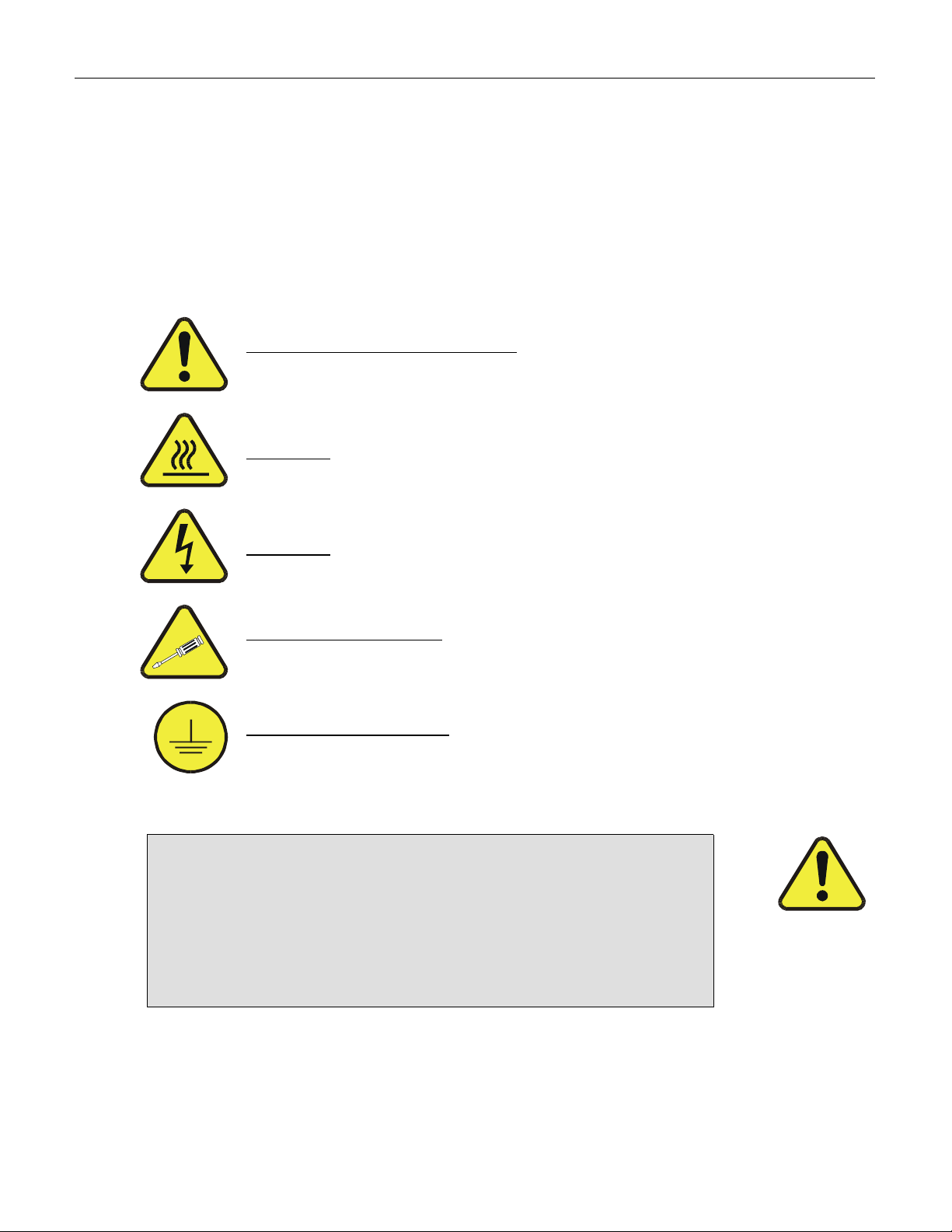
SAFETY MESSAGES
Your safety and the safety of others is very important. We have provided many important safety messages
in this manual. Please read these messages carefully.
A safety message alerts you to potential hazards that could hurt you or others. Each safety message is
associated with a safety alert symbol. These symbols are found in the manual and inside the instrument.
The definition of these symbols is described below:
GENERAL WARNING/CAUTION: Refer to the instructions for details on the
specific danger.
CAUTION: Hot Surface Warning
CAUTION
TECHNICIAN SYMBOL: All operations marked with this symbol are to be
performed by qualified maintenance personnel only.
ELECTRICAL GROUND: This symbol inside the instrument marks the central
safety grounding point for the instrument.
The analyzer should only be used for the purpose
and in the manner described in this manual.
If you use the analyzer in a manner other than that for which
it was intended, unpredictable behavior could ensue with
: Electrical Shock Hazard
CAUTION
possible hazardous consequences.
ii

Teledyne API Model 100AH SO2 Analyzer Instruction Manual, 02417, Rev. D
TABLE OF CONTENTS
SAFETY MESSAGES .........................................................................................II
TABLE OF CONTENTS .....................................................................................III
LIST OF FIGURES ........................................................................................... VII
LIST OF TABLES............................................................................................ VIII
1 HOW TO USE THIS MANUAL..................................................................... 1-1
2 GETTING STARTED.................................................................................... 2-1
NSTALLATION
2.1 I
LECTRICAL AND PNEUMATIC CONNECTIONS
2.2 E
NITIAL OPERATION
2.3 I
.................................................................................................................2-1
....................................................................2-2
.........................................................................................................2-7
3 SPECIFICATIONS, AGENCY APPROVALS, WARRANTY ........................ 3-1
PECIFICATIONS
3.1 S
3.2 W
ARRANTY
.............................................................................................................3-1
....................................................................................................................3-2
4 THE M100AH SO2 ANALYZER ................................................................... 4-1
RINCIPLE OF OPERATION
4.1 P
NSTRUMENT DESCRIPTION
4.2 I
4.2.1 Sensor Module, Reaction Cell, Detector................................................................4-3
4.2.2 Pneumatic Sensor Board.......................................................................................4-3
4.2.3 Computer Hardware and Software ........................................................................4-3
4.2.4 V/F Board ..............................................................................................................4-4
4.2.5 Front Panel............................................................................................................4-4
4.2.6 Power Supply Module............................................................................................4-7
4.2.7 Pneumatic System.................................................................................................4-7
4.3 I/O H
4.3.1 RS-232 Interface ...................................................................................................4-8
4.3.2 Status Output Interface........................................................................................4-11
4.3.3 Contact Closure Control Input Interface ..............................................................4-13
ARDWARE INTERFACE
...............................................................................................4-1
..............................................................................................4-3
.............................................................................................4-8
5 SOFTWARE FEATURES............................................................................. 5-1
NDEX TO FRONT PANEL MENUS
5.1 I
5.1.1 Sample Menu ........................................................................................................5-3
5.1.2 Set-Up Menu .........................................................................................................5-4
......................................................................................5-1
iii

Teledyne API Model 100AH SO2 Analyzer Instruction Manual, 02417, Rev. D
AMPLE MODE
5.2 S
...............................................................................................................5-7
5.2.1 Test Functions .......................................................................................................5-7
5.2.2 CAL, CALS, CALZ, Calibration Functions............................................................5-10
ET-UP MODE
5.3 S
.............................................................................................................5-12
5.3.1 Configuration Information (CFG) .........................................................................5-12
5.3.2 Automatic Calibration (AutoCal) ..........................................................................5-12
5.3.3 Data Acquisition System (DAS) ...........................................................................5-12
5.3.4 Range Menu........................................................................................................5-15
5.3.5 Password Enable.................................................................................................5-18
5.3.6 Time of Day Clock ...............................................................................................5-18
5.3.7 Diagnostic Mode..................................................................................................5-18
5.3.8 Communications Menu........................................................................................5-18
5.3.9 Variables Menu (VARS) ......................................................................................5-19
6 OPTIONAL HARDWARE AND SOFTWARE............................................... 6-1
ACK MOUNT OPTIONS
6.1 R
ERO/SPAN VALVES
6.2 Z
UTOCAL
6.3 A
6.4 4-20
M
A, I
ETUP ZERO/SPAN VALVES
- S
SOLATED CURRENT LOOP OUTPUT
...................................................................................................6-1
.......................................................................................................6-1
............................................................................6-2
...................................................................6-6
7 RS-232 INTERFACE .................................................................................... 7-1
ETTING UP THE
7.1 S
RS-232 I
7.1.1 Setup from the Front Panel ...................................................................................7-1
7.1.2 Security Feature ....................................................................................................7-2
7.1.3 Protocol of Port Communication............................................................................7-3
7.1.4 Entering Commands in Terminal Mode .................................................................7-4
7.2 C
OMMAND SUMMARY
7.3 TEST
7.4 WARNING C
7.5 CALIBRATION C
7.6 DIAGNOSTIC C
7.7 DAS C
7.8 VARIABLES C
COMMANDS AND MESSAGES
OMMANDS AND MESSAGES
OMMANDS AND MESSAGES
OMMANDS AND MESSAGES
OMMANDS AND REPORTS
OMMANDS AND MESSAGES
NTERFACE
..............................................................................7-1
......................................................................................................7-5
..................................................................................7-8
.........................................................................7-9
.................................................................7-11
..................................................................7-13
....................................................................................7-14
.....................................................................7-16
8 CALIBRATION AND ZERO/SPAN CHECKS .............................................. 8-1
8.1 M
8.2 M
8.3 A
8.4 D
8.5 U
8.6 S
8.7 C
8.8 C
ANUAL ZERO/SPAN CHECK OR CALIBRATION THROUGH THE SAMPLE PORT
ANUAL ZERO/SPAN CHECK OR CALIBRATION WITH ZERO/SPAN VALVES OPTION
UTOMATIC ZERO/SPAN CHECK
YNAMIC ZERO/SPAN CALIBRATION
SE OF ZERO/SPAN VALVES WITH REMOTE CONTACT CLOSURE
PECIAL CALIBRATION REQUIREMENTS FOR DUAL RANGE OR AUTO RANGE
ALIBRATION QUALITY
ALIBRATION GASES
....................................................................................................8-8
......................................................................................................8-9
......................................................................................8-6
.................................................................................8-6
........................................8-6
......................8-3
........................8-7
...............8-5
iv

Teledyne API Model 100AH SO2 Analyzer Instruction Manual, 02417, Rev. D
9 MAINTENANCE ........................................................................................... 9-1
9.1 M
9.2 R
9.3 R
9.4 C
9.5 C
9.6 P
9.7 L
9.8 L
9.9 EPROM R
AINTENANCE SCHEDULE
EPLACING THE SAMPLE PARTICULATE FILTER
EPLACING THE PUMP SCRUBBER
LEANING ORIFICE AND ORIFICE FILTER
LEANING THE REACTION CELL
NEUMATIC LINE INSPECTION
EAK CHECK PROCEDURE
IGHT LEAK CHECK PROCEDURE
EPLACEMENT PROCEDURE
...............................................................................................9-1
...................................................................................9-4
...........................................................................9-4
.......................................................................................9-5
..........................................................................................9-5
...............................................................................................9-8
.....................................................................................9-9
............................................................................9-10
.................................................................9-2
10 DIAGNOSTIC, TROUBLESHOOTING..................................................... 10-1
10.1 O
PERATION VERIFICATION
- M100AH D
10.1.1 Fault Diagnosis with TEST Variables ................................................................10-3
10.1.2 Fault Diagnosis with WARNING Messages.......................................................10-9
10.1.3 Fault Diagnosis using DIAGNOSTIC Mode .....................................................10-11
10.1.4 M100AH Internal Variables..............................................................................10-18
10.1.5 Test Channel Analog Output ...........................................................................10-20
10.1.6 Factory Calibration Procedure (Quick Cal) ......................................................10-21
10.2 P
ERFORMANCE PROBLEMS
........................................................................................10-23
10.2.1 AC Power Check .............................................................................................10-23
10.2.2 Flow Check......................................................................................................10-24
10.2.3 No Response to Sample Gas ..........................................................................10-24
10.2.4 Negative Concentration Display ......................................................................10-25
10.2.5 Excessive Noise ..............................................................................................10-25
10.2.6 Unstable Span .................................................................................................10-26
10.2.7 Unstable Zero ..................................................................................................10-26
10.2.8 Inability to Span ...............................................................................................10-27
10.2.9 Inability to Zero ................................................................................................10-27
10.2.10 Non-Linear Response....................................................................................10-28
10.2.11 Slow Response..............................................................................................10-28
10.2.12 Analog Output Doesn't Agree with Display Concentration.............................10-28
10.3 E
LECTRONIC SUBSYSTEM TROUBLESHOOTING AND ADJUSTMENTS
10.3.1 Computer, Display, Keyboard..........................................................................10-29
10.3.2 Voltage/Frequency (V/F) Board .......................................................................10-33
10.3.3 Status/Temp Board..........................................................................................10-38
10.3.4 Power Supply Module......................................................................................10-41
10.3.5 Flow/Pressure Sensor .....................................................................................10-45
10.3.6 Reaction Cell Temp .........................................................................................10-49
10.3.7 Preamp Board .................................................................................................10-49
10.3.8 PMT Cooler .....................................................................................................10-50
10.3.9 HVPS (High Voltage Power Supply)................................................................10-52
IAGNOSTIC TECHNIQUES
...................................10-3
...............................10-29
v

Teledyne API Model 100AH SO2 Analyzer Instruction Manual, 02417, Rev. D
10.4 O
PTICAL SENSOR MODULE TROUBLESHOOTING
..........................................................10-54
10.4.1 PMT.................................................................................................................10-54
10.4.2 UV Lamp Adjust or Replacement ....................................................................10-54
10.5 P
NEUMATIC SYSTEM TROUBLESHOOTING
...................................................................10-56
10.5.1 Leak Check......................................................................................................10-56
10.5.2 Pump ...............................................................................................................10-56
10.5.3 Z/S Valves .......................................................................................................10-56
11 M100AH SPARE PARTS LIST ................................................................ 11-1
11.1 M
ODEL
100AH L
EVEL
PARES KIT
1 S
...........................................................................11-3
APPENDIX A MAINTENANCE SCHEDULE FOR M100AH ...........................A-1
APPENDIX B ELECTRICAL SCHEMATICS ..................................................B-1
vi

Teledyne API Model 100AH SO2 Analyzer Instruction Manual, 02417, Rev. D
LIST OF FIGURES
IGURE
F
IGURE
F
IGURE
F
IGURE
F
IGURE
F
IGURE
F
IGURE
F
IGURE
F
IGURE
F
IGURE
F
IGURE
F
IGURE
F
IGURE
F
IGURE
F
IGURE
F
IGURE
F
IGURE
F
IGURE
F
IGURE
F
IGURE
F
IGURE
F
IGURE
F
IGURE
F
IGURE
F
2-1: R
2-2: R
2-3: R
2-4: F
2-5: A
EMOVAL OF SHIPPING SCREWS
EAR PANEL
EAR PANEL PNEUMATIC RECOMMENDATIONS
RONT PANEL
SSEMBLY LAYOUT
4-1: M100AH S
4-2: F
RONT PANEL DISPLAY
4-3: RS-232 P
4-4: I
5-1: S
5-2: S
8-1: M
9-1: R
9-2: R
9-3: P
NTERFACING CONTACT CLOSURE
AMPLE MENU
ETUP MENU TREE
ODEL
100AH C
EPLACING THE PARTICULATE FILTER
EACTION CELL
NEUMATIC DIAGRAM
10-1: CPU B
10-2: V/F B
10-3: P
10-4: E
10-5: P
10-6: SO
10-7: SO
OARD DIP SWITCH SETTINGS
OWER SUPPLY MODULE LAYOUT
LECTRICAL BLOCK DIAGRAM
RESSURE/FLOW SENSOR
SENSOR MODULE
2
SENSOR MODULE
2
10-8: PMT C
10-9: H
IGH VOLTAGE POWER SUPPLY
...........................................................................2-4
........................................................................................................2-5
.......................................................2-6
....................................................................................................2-10
............................................................................................2-11
ULFUR DIOXIDE ANALYZER
...................................................................4-2
........................................................................................4-6
IN ASSIGNMENTS
..................................................................................4-9
I/O..................................................................4-12
.....................................................................................................5-2
..............................................................................................5-2
ALIBRATION SETUP
.....................................................................8-2
...................................................................9-3
...................................................................................................9-6
...........................................................................................9-7
OARD JUMPER SETTINGS
.....................................................................10-31
..................................................................10-37
...................................................................10-42
.........................................................................10-43
..............................................................................10-46
...................................................................................10-47
...................................................................................10-48
OOLER SUBSYSTEM
.............................................................................10-51
......................................................................10-53
vii

Teledyne API Model 100AH SO2 Analyzer Instruction Manual, 02417, Rev. D
LIST OF TABLES
ABLE
T
ABLE
T
ABLE
T
ABLE
T
ABLE
T
ABLE
T
ABLE
T
ABLE
T
ABLE
T
ABLE
T
ABLE
T
ABLE
T
ABLE
T
ABLE
T
ABLE
T
ABLE
T
ABLE
T
ABLE
T
ABLE
T
ABLE
T
ABLE
T
ABLE
T
ABLE
T
ABLE
T
ABLE
T
ABLE
T
ABLE
T
ABLE
T
ABLE
T
ABLE
T
ABLE
T
ABLE
T
ABLE
T
ABLE
T
ABLE
T
ABLE
T
ABLE
T
2-1: F
2-1: F
4-1: S
4-2: F
4-3: S
5-1: M100AH S
5-2: M100AH S
5-3: M100AH M
5-4: M100AH M
5-5: C
6-1: Z
6-2: S
7-1: RS-232 P
7-2: RS-232 S
7-3: RS-232 T
7-4: RS-232 I
7-5: RS-232 C
7-6: RS-232 C
7-7: RS-232 T
7-8: RS-232 W
7-9: RS-232 C
7-10: RS-232 C
7-11: RS-232 D
INAL TEST AND CALIBRATION VALUES
INAL TEST AND CALIBRATION VALUES (CONTINUED
YSTEM MODES DISPLAY
RONT PANEL STATUS
TATUS OUTPUT PIN ASSIGNMENTS
AMPLE MENU STRUCTURE
ETUP MENU STRUCTURE
ENU STRUCTURE
ENU STRUCTURE
ALIBRATE
ERO/SPAN VALVE OPERATION
ETUP AUTOMATIC ZERO/SPAN CALIBRATION
ETUP PASSWORDS
, S
ORT SETUP
WITCHING FROM TERMINAL MODE TO COMPUTER MODE
ERMINAL MODE EDITING KEYS
NTERFACE COMMAND TYPES
OMMAND SUMMARY
OMMAND SUMMARY
EST MESSAGES
ARNING MESSAGES
ALIBRATION MESSAGES
ALIBRATION COMMANDS
IAGNOSTIC COMMAND SUMMARY
7-12: RS-232 DAS C
7-13: RS-232 O
8-1: T
8-2: M
8-3: E
8-4: M
8-5: M
8-6: M
8-7: Z/S V
8-8: C
9-1: P
10-1: T
10-1: T
10-1: T
YPES OF ZERO/SPAN CHECKS AND CALIBRATIONS
ANUAL ZERO CALIBRATION PROCEDURE
NTER EXPECTED SPAN GAS CONCENTRATION PROCEDURE
ANUAL SPAN CALIBRATION PROCEDURE
ANUAL ZERO CALIBRATION PROCEDURE
ANUAL SPAN CALIBRATION PROCEDURE
ALVES MODE WITH REMOTE CONTACT CLOSURE
ALIBRATION QUALITY CHECK
REVENTATIVE MAINTENANCE SCHEDULE
EST FUNCTIONS
EST FUNCTIONS (CONTINUED
EST FUNCTIONS (CONTINUED
PERATING MODES
..................................................................2-12
) .............................................2-13
.......................................................................................4-5
LED'S.................................................................................4-7
......................................................................4-11
.....................................................................5-3
.......................................................................5-4
ETUP MENU
- S
ETUP MENU
- S
#2 ......................................................5-5
#3 ......................................................5-6
..........................................................................5-18
..............................................................................6-1
..........................................................6-3
RONT PANEL
- F
....................................................................7-2
...........................7-3
.................................................................7-4
....................................................................7-5
................................................................................7-6
................................................................................7-7
......................................................................................7-8
...............................................................................7-9
........................................................................7-11
......................................................................7-12
.........................................................7-13
OMMANDS
.................................................................................7-14
..............................................................................7-16
..................................................8-1
ERO GAS THROUGH SAMPLE PORT
- Z
.......8-3
....................................8-4
PAN GAS THROUGH SAMPLE PORT
- S
- Z/S V
- Z/S V
ALVES
ALVES
..........................................8-5
..........................................8-5
........8-4
.............................................8-7
................................................................................8-8
................................................................9-1
...............................................................................................10-3
) ..........................................................................10-4
) ..........................................................................10-5
viii

Teledyne API Model 100AH SO2 Analyzer Instruction Manual, 02417, Rev. D
ABLE
T
ABLE
T
ABLE
T
ABLE
T
ABLE
T
ABLE
T
ABLE
T
ABLE
T
ABLE
T
ABLE
T
ABLE
T
ABLE
T
ABLE
T
ABLE
T
ABLE
T
ABLE
T
ABLE
T
ABLE
T
10-1: T
10-1: T
10-1: T
10-2: F
10-2: F
10-3: S
10-4: D
10-4: D
10-4: D
10-4: D
10-5: M
10-6: T
10-7: P
10-8: P
11-1: T-API M100AH S
11-1: T-API M100AH S
11-2: T-API M100AH L
EST FUNCTIONS (CONTINUED
EST FUNCTIONS (CONTINUED
EST FUNCTIONS (CONTINUED
RONT PANEL WARNING MESSAGES
RONT PANEL WARNING MESSAGES (CONTINUED
UMMARY OF DIAGNOSTIC MODES
IAGNOSTIC MODE
IAGNOSTIC MODE
IAGNOSTIC MODE
IAGNOSTIC MODE
ODEL
100AH V
EST CHANNEL OUTPUT
OWER SUPPLY MODULE SUBASSEMBLIES
OWER SUPPLY MODULE
ARIABLES
PARE PARTS LIST
PARE PARTS LIST (CONTINUED
EVEL
11-3: T-API M100AH 47
) ..........................................................................10-6
) ..........................................................................10-7
) ..........................................................................10-8
...................................................................10-9
).............................................10-10
....................................................................10-12
IGNAL
- S
- S
- S
- S
IGNAL
IGNAL
IGNAL
I/O.......................................................................10-13
I/O (C
I/O (C
I/O (C
ONTINUED
ONTINUED
ONTINUED
) ..................................................10-14
) ..................................................10-15
) ..................................................10-16
...............................................................................10-19
...................................................................................10-20
........................................................10-41
LED O
PERATION
.......................................................10-44
...................................................................11-1
)...............................................11-2
PARES KIT
1 S
MM EXPENDABLES KIT
.................................................................11-3
..........................................................11-3
ix

Teledyne API Model 100AH SO2 Analyzer Instruction Manual, 02417, Rev. D
INTENTIONALLY BLANK
x

Teledyne API Model 100AH SO2 Analyzer Instruction Manual, 02417, Rev. D
1 HOW TO USE THIS MANUAL
The Model 100AH has been designed with serviceability, reliability and ease of operation in
mind. The M100AH's microprocessor continually checks operating parameters such as
temperature, flow, and critical voltages. The instruments modular design uses captive screws to
facilitate repair and ease of access. If you encounter any difficulty refer to Section 10 General
Troubleshooting Hints.
We recognize that the need for information in this manual changes as time passes. When the
instrument first arrives, it is necessary to get it up and running quickly and verify its correct
operation. As time passes, more detailed information is often required on special configurations,
calibration alternatives and other operational details. Finally there is the need for periodic
maintenance and to quickly troubleshoot problems to assure maximum uptime and data integrity.
To address these needs, we have created three indexes to the information inside. They are:
Table of Contents:
Outlines the contents of the manual in the order the information is presented. This is a good
overview of the topics covered in the manual. There is also a list of Tables and a list of Figures.
Index to M100AH Front Panel Menus:
The Menu Index (Figure 5-1, Figure 5-2 and Table 5-2) briefly describes the front panel menus and
refers you to other sections of the manual that have a detailed explanation of each menu selection.
Troubleshooting Section 10:
The Troubleshooting Section, outlined in the Table of contents, allows you to diagnose and repair
the instrument based on variables in the TEST menu, the results of DIAGNOSTIC tests, and
performance faults such as excessive noise or drift. The troubleshooting section also explains the
operation, adjustment, diagnosis and testing of each instrument subsystem.
If you are unpacking the instrument for the first time, please refer to Getting Started in
Section 2.
1-1

Teledyne API Model 100AH SO2 Analyzer Instruction Manual, 02417, Rev. D
INTENTIONALLY BLANK
1-2
Teledyne API Model 100AH SO2 Analyzer Instruction Manual, 02417, Rev. D
2 GETTING STARTED
2.1 Installation
CAUTION
To avoid personal injury, always use two persons to
lift and carry the Model 100AH.
1. Verify that there is no apparent shipping damage. If damage has occurred please advise
shipper first, then Teledyne API.
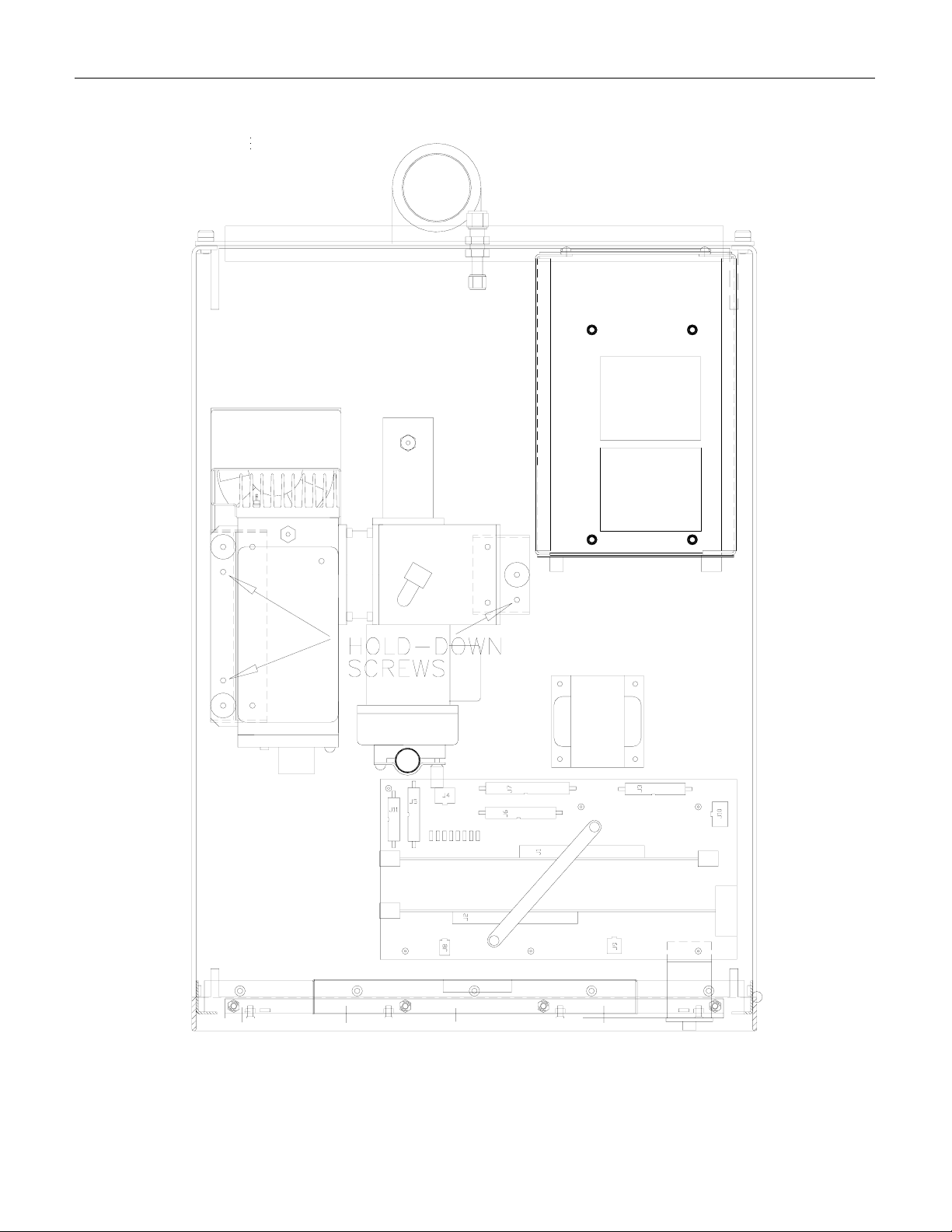
2. Before operation it is necessary to remove the shipping hold-down screws. Remove the
instrument cover, then refer to Figure 2-1 for screw location.
NOTE
Save these shipping screws and re-install then whenever the
unit is shipped to another location.
3. While the instrument cover is removed, please check the voltage and frequency label on the
cover of the power supply module and compare that to your local power before plugging in
the M100AH.
4. Check for internal shipping damage, and generally inspect the interior of the instrument to
make sure all circuit boards and other components are in good shape.
5. Replace the instrument cover.
6. When installing the M100AH, allow at least 4” (100 mm) clearance at the back and at least
1” (25 mm) clearance at each side for proper venting.
2-1

Teledyne API Model 100AH SO2 Analyzer Instruction Manual, 02417, Rev. D
2.2 Electrical and Pneumatic Connections
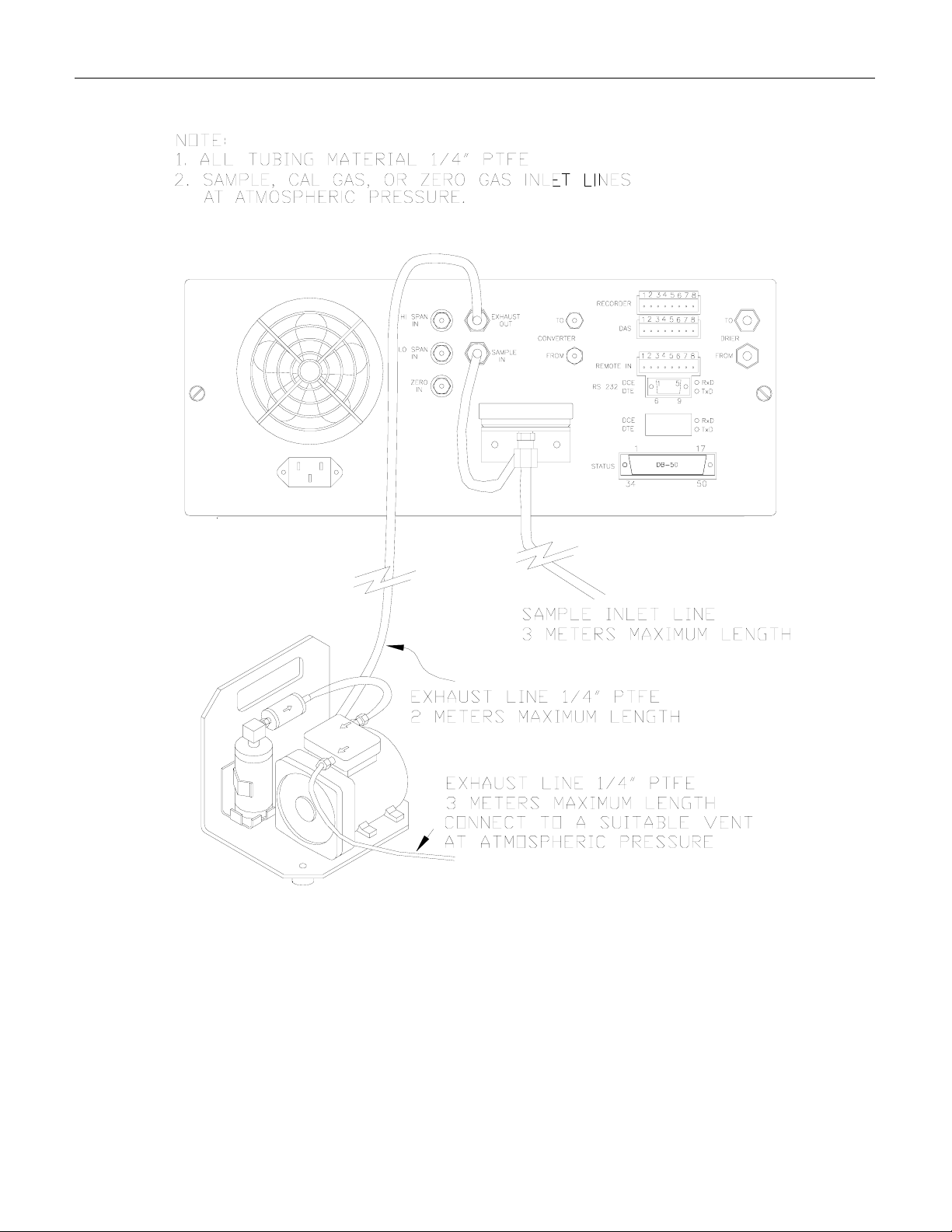
1. Refer to Figure 2-2 to locate the rear panel electrical and pneumatic connections.
2. The pressure of the sample gas at the inlet port should be at atmospheric pressure (±2”Hg).
Refer Figure 2-3 and Figure 8-1 for pneumatic system connection.
3. Attach the pump to the “Exhaust Out” port on the instrument rear panel. The exhaust from
the pump also should be vented to a suitable vent at atmospheric pressure. (See Figure 2-3
for exhaust line venting recommendations.)
4. If desired, attach the analog output connections to a strip chart recorder and/or datalogger.
Non-isolated 4-20mA current output is standard. Each 4-20 mA current output should be
connected to one interfacing device only.
5. Connect the power cord to the correct voltage line, then turn to Section 2.3 Initial Operation.
WARNING – Analyzer Exhaust
Danger – Analyzer exhaust may contain high concentration of SO2
gas. Exhaust properly from the pump pack exhaust to well ventilated
area at atmospheric pressure.
CAUTION
High voltages present inside case.
DO NOT LOOK AT THE UV LAMP.
UV LIGHT COULD CAUSE EYE DAMAGE.
ALWAYS USE SAFETY GLASSES
(PLASTIC GLASSES WILL NO DO).
Connect the exhaust fitting of the pump to a suitable
vent outside of the room.
2-2

Teledyne API Model 100AH SO2 Analyzer Instruction Manual, 02417, Rev. D
CAUTION
Do not operate with cover off.
Before operation check for correct input
voltage and frequency on serial number sticker.
Do not plug in the power cord if the voltage or
frequency is incorrect.
Do no operate without proper chassis grounding.
Do not defeat the ground wire on power plug.
Turn off analyzer power before disconnecting or
connecting electrical subassemblies.
Always replace shipping screws when transporting the Analyzer.
2-3
Teledyne API Model 100AH SO2 Analyzer Instruction Manual, 02417, Rev. D
Figure 2-1: Removal of Shipping Screws
2-4

Teledyne API Model 100AH SO2 Analyzer Instruction Manual, 02417, Rev. D
Figure 2-2: Rear Panel
2-5
Teledyne API Model 100AH SO2 Analyzer Instruction Manual, 02417, Rev. D
Figure 2-3: Rear Panel Pneumatic Recommendations
2-6

Teledyne API Model 100AH SO2 Analyzer Instruction Manual, 02417, Rev. D
2.3 Initial Operation
1. Turn on the instrument power.
2. The display should immediately light, displaying the instrument type (M100AH) and the
CPU memory configuration. If you are unfamiliar with the M100AH, we recommend that
you read the overview Section 4 before proceeding. A diagram of the software menu trees is
in Figure 5-1 and Figure 5-2.
3. The M100AH requires about 30 minutes for all internal components to come up to
temperature.
4. While waiting for instrument temperatures to come up, you can check for correct operation
by using some of the M100AH's diagnostic and test features.
5. Examine the TEST functions by comparing the values listed in Table 2-1 to those in the
display. Remember that as the instrument warms up the values may not have reached their
final values yet. If you would like to know more about the meaning and utility of each TEST
function refer to Table 10-1. Table 2-1 also contains the list of options. Section 6 covers
setting up the options.
6. When the instrument is warmed up, re-check the TEST functions against Table 2-1. All of
the readings should compare closely with those in the Table. If they do not, see
Section 10.1.1.
2-7
Teledyne API Model 100AH SO2 Analyzer Instruction Manual, 02417, Rev. D
The next task is to calibrate the analyzer. There are several ways to do a calibration; they are
summarized in Table 7-1. For a preliminary checkout we recommend calibration with zero air
and span gas coming in through the sample port. The procedure is:
WARNING – Analyzer Exhaust
Danger – Analyzer exhaust may contain high concentration of
SO2 gas. Exhaust properly from the pump pack exhaust to well
ventilated area at atmospheric pressure.
Step 1 - Enter the expected SO
Step Number Action Comment
1. Press CAL-CONC This key sequence causes the M100AH to prompt for the
2. Press ENTR ENTR stores the expected SO2 span value. This value will be
3. Press EXIT Returns instrument to SAMPLE mode.
4. Press SETUPRNGE-SET
5. Press EXIT Returns the instrument to SAMPLE mode.
span gas concentration:
2
expected SO
concentration value by pressing the key under each digit until
the expected value is set.
used in the internal formulas to compute subsequent SO
concentration values.
If necessary you may want to change ranges. Normally the
instrument is shipped in single range mode set at 500 PPM.
(see Section 5.3.4 for Range Menu)
concentration. Enter the SO2 span
2
2
2-8
Teledyne API Model 100AH SO2 Analyzer Instruction Manual, 02417, Rev. D
Step 2 - Calibrate the instrument:
Initial Zero/Span Calibration Procedure
Step Number Action Comment
1. Input Zero gas Allow Zero gas to enter the sample port on the rear of the
instrument.
2. Press CAL The M100AH enters the calibrate mode from sample mode.
3. Wait 5 - 10 min Wait for reading to stabilize at the zero value. (If you wait
less than 5 - 10 minutes the final zero value may drift.)
4. Press ZERO The ENTR button will be displayed.
5. Press ENTR Pressing ENTR actually changes the calculation equations
and zeroes the instrument.
6. Press EXIT M100AH returns to the CAL menu. Allow SPAN gas to enter
the sample port on the rear of the instrument.
7. Wait 5 - 10 min Wait for reading to stabilize at the span value. (If you wait
less than 5 -10 minutes the final span value may drift.)
8. Press SPAN If SPAN button is not displayed, check the Troubleshooting
Section 10.2.8 for instructions on how to proceed. In certain
circumstances at low span gas concentrations (<100PPM),
both the ZERO and SPAN buttons will appear. This is
acceptable and just do not press ZERO button.
9. Press ENTR Pressing ENTR actually changes the calculation equations so
that the concentration displayed is the same as the expected
span concentration you entered above, thus spanning the
instrument.
10. Press EXIT Pressing EXIT returns the instrument to SAMPLE mode.
Step 3 - Review the quality of the calibration:
Calibration Quality Check Procedure
Step Number Action Comment
1. Scroll the TEST
function menu until
SLOPE is
displayed.
2. Scroll the TEST
function menu until
OFFSET is
displayed.
Typical SLOPE value is 1.0 ± 0.3. If the value is not in this
range, check Section 8.7 or 10. If the SLOPE value is in the
acceptable range the instrument will perform optimally.
The M100AH will display the OFFSET parameter for the
equation. A value less than 200mV indicates calibration
SO
2
in the optimal range. If the OFFSET value is outside this
range, check Section 8.7 and 10.
Step 4 - The M100AH is now ready to measure sample gas.
2-9
Teledyne API Model 100AH SO2 Analyzer Instruction Manual, 02417, Rev. D
Figure 2-4: Front Panel
2-10
Teledyne API Model 100AH SO2 Analyzer Instruction Manual, 02417, Rev. D
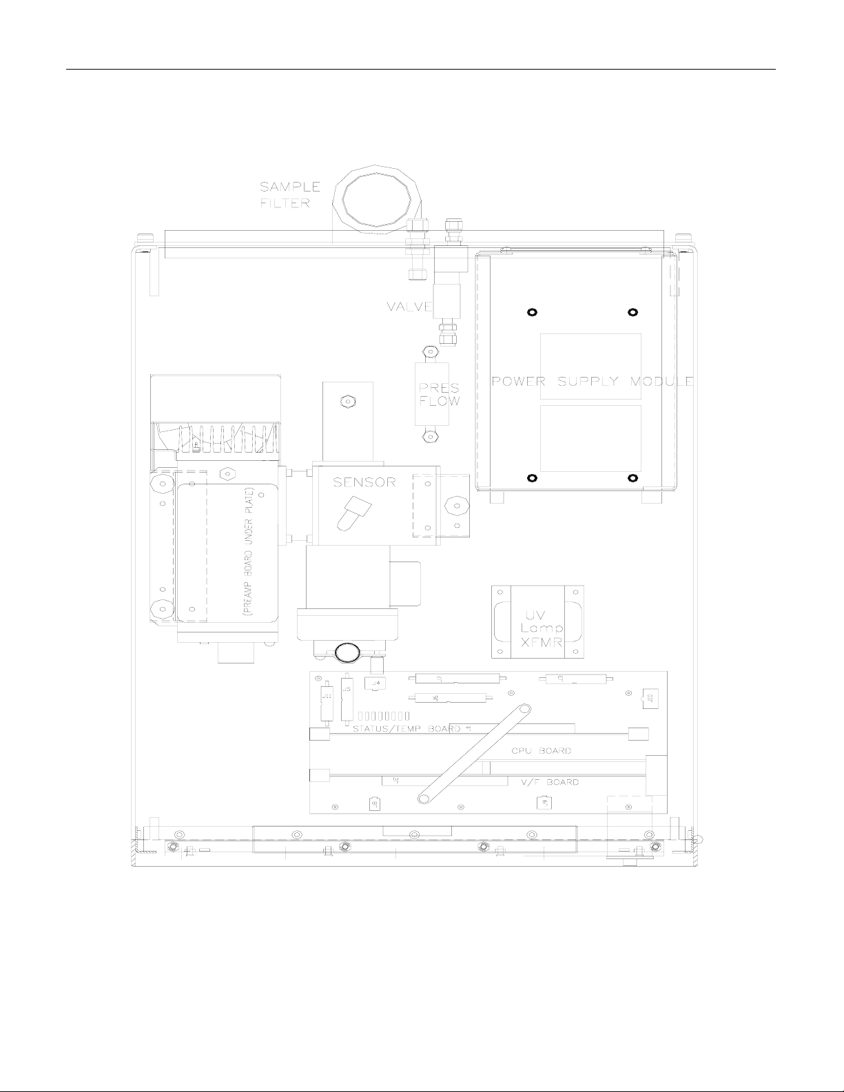
Figure 2-5: Assembly Layout
2-11
Teledyne API Model 100AH SO2 Analyzer Instruction Manual, 02417, Rev. D
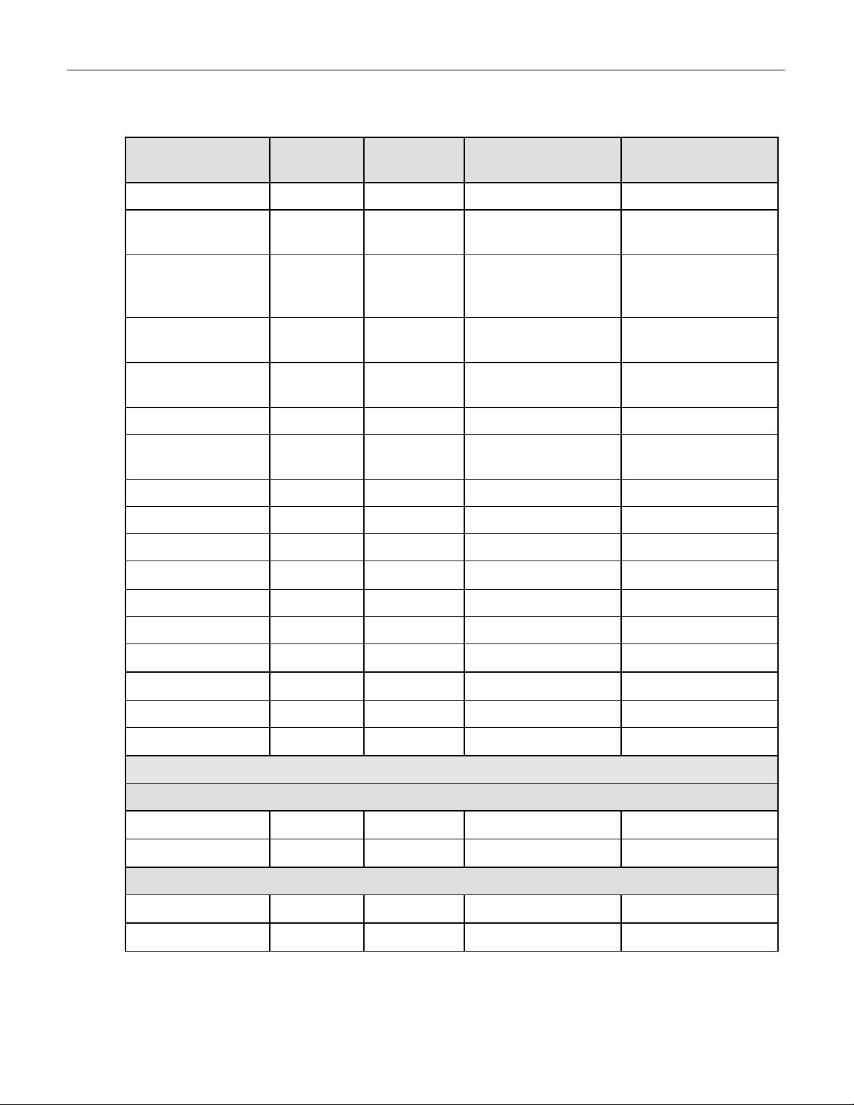
Table 2-1: Final Test and Calibration Values
Test Values
Observed
Value
Units Nominal Range Reference Section
RANGE PPM 10 - 5000 5.3.4
STABIL PPM 0.01 - 0.05 5.2.1, 10.1.1,
10.2.5, Table 10-1
INLET
SAMPLE
in-Hg-
Abs
25 - 35 10.1.1, 10.3.5,
Table 10-1
PRESS
VACUUM
PRESS
SAMP FL CC / MIN
in-Hg-
Abs
4 - 10 10.3.5, Table 10-1
650 ± 60
10.2.2, 10.3.5,
Table 10-1
PMT mV 0 - 5000 10.4.1
UV LAMP mV 2000 - 4000
10.4.2
typical
STR. LGT PPM <100.0 Table 10-1
DARK PMT mV <200 Table 10-1
DARK LAMP mV <200 Table 10-1
SLOPE
1.0 ± 0.3
8.7
OFFSET mV <200 8.7
HVPS V 450 - 900 constant 10.3.9
DCPS mV
RCELL TEMP
BOX TEMP
PMT TEMP
o
C
o
C 8 - 50 10.3.3.1
o
C
2500 ± 200
50 ± 1
7 ± 1
10.3.4
10.3.6
10.3.8
Electric Test & Optic Test
Electric Test
PMT Volts mV
SO2 Conc PPM
2000 ± 100
2000 ± 100
10.1.3.2
10.1.3.2
Optic Test
PMT Volts mV
SO2 Conc PPM
200 ± 20
200 ± 20
10.1.3.3
10.1.3.3
2-12
Teledyne API Model 100AH SO2 Analyzer Instruction Manual, 02417, Rev. D
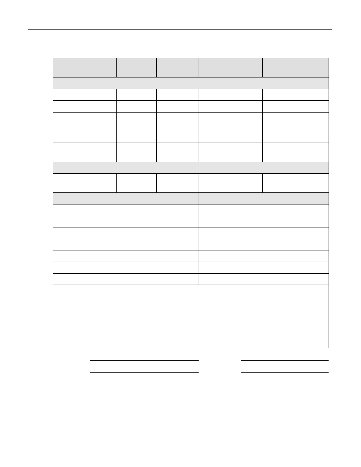
Table 2-1: Final Test and Calibration Values (Continued)
Parameter
SO2 Span Conc PPM 100 - 4500 Table 8-3
SO2 Slope
SO2 Offset mV <100 8.7
Noise at Zero
(rms)
Noise at Span
(rms)
Sample Flow cc/min
Factory Installed Options Option Installed
Power Voltage/Frequency
Rack Mount, w/ Slides
Rack Mount, w/ Ears Only
Observed
Value
PPM 0.05 - 0.2 Table 10-1
PPM 0.5% of reading
Units Nominal Range Reference Section
Span and Cal Values
1.0 ± 0.3
(above 50PPM)
Measured Flows
650 ± 60
8.7
Table 10-1
10.2.2, 10.3.5,
Figure 10-5
Zero/Span Valves Manifold
Multi-drop
Kicker
37 mm Filter
4-20 mA Isolated Current Loop Output
(non-isolated standard)
SO2 (RANGE 1) ____________ ____________
SO2 (RANGE 2) ____________ ____________
SPARE ____________ ____________
TEST OUTPUT ____________ ____________
ISOLATED NON-ISOLATED
PROM # Serial #
Date Technician
2-13

Teledyne API Model 100AH SO2 Analyzer Instruction Manual, 02417, Rev. D
INTENTIONALLY BLANK
2-14

Teledyne API Model 100AH SO2 Analyzer Instruction Manual, 02417, Rev. D
3 SPECIFICATIONS, AGENCY APPROVALS,
WARRANTY
3.1 Specifications
Ranges In 1 PPM increments from 10 PPM to 5000 PPM, dual ranges or autoranging
Noise at Zero 0.05 PPM RMS
Noise at Span <0.5% of reading (above 50 PPM)
Lower Detectable Limit
Zero Drift
Zero Drift
Span Drift
2
< 1 PPM/24 hours
2
<2 PPM/7 days
2
<0.5% FS/7 days
Lag Time 5 sec
Rise Time 95% in < 30 sec
Fall Time 95% in < 30 sec
Sample Flow Rate
Linearity 1% of full scale
Precision 0.5% of reading
Temperature Range 5 - 40
Temp Coefficient < 0.1% per
Humidity 0 - 95% RH, non-condensing
Voltage Coefficient < 0.05% per V
Dimensions HxWxD 7"x17"x23.6" (18 cm x 43 cm x 61 cm)
Weight, Analyzer 43 lbs (19.5 kg)
Weight, Pump Pack 16 lbs (7 kg)
Power, Analyzer
Power, Analyzer
3
Power, Ext. Pump
Power, Ext. Pump
Environmental
Conditions
Recorder Output
4
Status Option 12 Status Outputs from opto-isolator
Measurement Units PPM, mg/m
1
0.1 PPM RMS
650cc/min. ±10%
o
C
o
C
110 v∼60 Hz, 220 v∼50 Hz, 240 v∼50 Hz, 250 watts
3
230 v∼50 Hz, 2.5A
110 v∼60 Hz, 220 v∼50 Hz, 240 v∼50 Hz, 295 watts
230 v∼50 Hz, 2.5 A
Installation Category (Overvoltage Category) II
Pollution Degree 2
4 - 20 mA non-isolated standard, 0-100 mV, 0-1, 5, 10 v ; resolution of 1 part
in 1024 of selected voltage or current range. 4 - 20 mA isolated optional.
3
1. Defined as twice the zero noise level.
2. At constant temperature and voltage.
3. Electrical ratings for CE Mark compliance.
4. Bi-polar. (voltage or current selectable by the jumper on the motherboard)
3-1

Teledyne API Model 100AH SO2 Analyzer Instruction Manual, 02417, Rev. D
3.2 Warranty
WARRANTY POLICY (02024c)
Prior to shipment, Teledyne API equipment is thoroughly inspected and tested. Should
equipment failure occur, Teledyne API assures its customers that prompt service and support
will be available.
COVERAGE
After the warranty period and throughout the equipment lifetime, Teledyne API stands ready to
provide on-site or in-plant service at reasonable rates similar to those of other manufacturers in
the industry. All maintenance and the first level of field troubleshooting is to be performed by
the customer.
NON-TELEDYNE API MANUFACTURED EQUIPMENT
Equipment provided but not manufactured by Teledyne API is warranted and will be repaired to
the extent and according to the current terms and conditions of the respective equipment
manufacturers warranty.
GENERAL
Teledyne API warrants each Product manufactured by Teledyne API to be free from defects in
material and workmanship under normal use and service for a period of one year from the date of
delivery. All replacement parts and repairs are warranted for 90 days after the purchase.
If a Product fails to conform to its specifications within the warranty period, Teledyne API shall
correct such defect by, in Teledyne API's discretion, repairing or replacing such defective
Product or refunding the purchase price of such Product.
The warranties set forth in this section shall be of no force or effect with respect to any Product:
(i) that has been altered or subjected to misuse, negligence or accident, or (ii) that has been used
in any manner other than in accordance with the instruction provided by Teledyne API or (iii)
not properly maintained.
THE WARRANTIES SET FORTH IN THIS SECTION AND THE REMEDIES
THEREFORE ARE EXCLUSIVE AND IN LIEU OF ANY IMPLIED WARRANTIES OF
MERCHANTABILITY, FITNESS FOR PARTICULAR PURPOSE OR OTHER
WARRANTY OF QUALITY, WHETHER EXPRESSED OR IMPLIED. THE
REMEDIES SET FORTH IN THIS SECTION ARE THE EXCLUSIVE REMEDIES FOR
BREACH OF ANY WARRANTY CONTAINED HEREIN. TELEDYNE API SHALL
NOT BE LIABLE FOR ANY INCIDENTAL OR CONSEQUENTIAL DAMAGES
ARISING OUT OF OR RELATED TO THIS AGREEMENT OF TELEDYNE API'S
PERFORMANCE HEREUNDER, WHETHER FOR BREACH OF WARRANTY OR
OTHERWISE.
3-2

Teledyne API Model 100AH SO2 Analyzer Instruction Manual, 02417, Rev. D
TERMS AND CONDITIONS
All units or components returned to Teledyne API should be properly packed for handling and
returned freight prepaid to the nearest designated Service Center. After the repair, the equipment
will be returned, freight prepaid.
3-3

Teledyne API Model 100AH SO2 Analyzer Instruction Manual, 02417, Rev. D
INTENTIONALLY BLANK
3-4

Teledyne API Model 100AH SO2 Analyzer Instruction Manual, 02417, Rev. D
4 THE M100AH SO2 ANALYZER
4.1 Principle of Operation
The operation of Teledyne API Model 100AH Analyzer is based upon the well proven technology
from the measurement of fluorescence of SO
absorbs in the 190 nm - 230 nm region free of quenching by air and relatively free of other
interference.
The UV lamp emits ultraviolet radiation which passes through a 214 nm filter (allowing 214 nm
light through), exciting the SO
molecules and producing fluorescence which is measured by a PMT
2
with a secondary UV filter. The equations describing the above reactions are as follows:
due to absorption of UV energy. Sulfur Dioxide
2
Ia
→+ (1)
12
*2SOhvSO
The ultraviolet light at any point in the system is given by:
()()
[]
SOaxexp1IIa −−= (2)
20
Where I0 is the UV light intensity, a is the absorption coefficient of SO2, x the path length, and (SO2)
the concentration of SO
. The excited SO2 decays back to the ground state emitting a characteristic
2
fluorescence:
KF
2
hvSO*SO +→ (3)
22
The block diagram in Figure 4-1 illustrates the general operation principle of the Model 100AH.
Ultraviolet light is focused through a narrow 214 nm bandpass filter into the reaction chamber. Here
it excites the SO
vacuum to minimize quenching effect from CO
molecules, which give off their characteristic decay radiation. The sample is under
2
and O2. A second filter allows only the decay
2
radiation to fall on the PMT. The PMT transfers the light energy into the electrical signal in the
sample stream being analyzed. The preamp board converts this signal into a voltage which is further
conditioned by the signal processing electronics.
The UV light source is measured by a UV detector. Software calculates the ratio of the PMT output
and the UV detector in order to compensate for variations in the UV light energy. Stray light is the
background light produced with zero PPM SO
will convert this electrical signal into the SO
. Once this background light is subtracted, the CPU
2
concentration.
2
4-1

Teledyne API Model 100AH SO2 Analyzer Instruction Manual, 02417, Rev. D
Figure 4-1: M100AH Sulfur Dioxide Analyzer
4-2

Teledyne API Model 100AH SO2 Analyzer Instruction Manual, 02417, Rev. D
4.2 Instrument Description
4.2.1 Sensor Module, Reaction Cell, Detector
The sensor module (Figure 10-6) is where the fluorescence light is generated and detected. It is
the most complicated and critical sub-assembly in the entire analyzer. It consists of the following
assemblies and functions:
1. The reaction cell
2. Reaction cell heater/thermistor
3. PMT and HVPS (high voltage power supply)
4. PMT cooler/cold block/heatsink/fan
5. Preamp assembly:
A. Preamp range control hardware
B. HVPS control
C. PMT cooler temp control
6. Electric and optic test electronics
7. Light trap
8. UV lamp and UV detector
4.2.2 Pneumatic Sensor Board
The pneumatic sensor board consists of two pressure sensors mounted on the flow control
module. One pressure sensor measures the upstream of the flow control module which is near
ambient pressure. The second pressure sensor measures reaction cell’s pressure which is about
one-quarter of ambient pressure. From these two pressure the sample flow rate can be computed
and is displayed as sample flow in the test menu including two pressure readings. The M100AH
displays pressure in inches of mercury-absolute (in-Hg-A) and flow in cc/min.
4.2.3 Computer Hardware and Software
The M100AH Analyzer is operated by a micro computer. The computer's multitasking operating
system allows it to do instrument control, monitor test points, provide analog output and provide
a user interface via the display, keyboard and RS-232 port. These operations appear to be
happening simultaneously but are actually done sequentially based on a priority queuing system
maintained by the operating system. The jobs are queued for execution only when needed,
therefore the system is very efficient with computer resources.
4-3

Teledyne API Model 100AH SO2 Analyzer Instruction Manual, 02417, Rev. D
The M100AH is a true computer based instrument. The microprocessor does most of the
instrument control functions such as temperature control, and valve switching. Data collection
and processing are done entirely in the CPU with the final concentration values being sent to a
D/A converter to produce the instrument analog output.
The computer memory is divided into 3 sections: EPROM memory contains the multi-tasking
operating system code plus the instructions that run the instrument. The RAM memory is used to
hold temporary variables and current concentration data. The EEPROM memory contains the
instrument set-up variables such as range and instrument ID number. The EEPROM data is nonvolatile so the instrument can lose power and the current set-up information is preserved.
4.2.4 V/F Board
Computer communication is done via 2 major hardware assemblies. These are the V/F board and
the front panel display/keyboard.
The V/F board is multifunctional, consisting of A/D input channels, digital I/O channels, and
analog output channels. Communication with the computer is via a STD bus interface. The
computer receives all of the instrument data and provides all control functions through the V/F
board.
4.2.5 Front Panel
The front panel of the M100AH is shown in Figure 2-4. The front panel consists of a 2 line
display and keyboard, 3 status LED's and power switch. Communication with the display,
keyboard, and status LED's is done via the computer's on-board parallel port. The M100AH was
designed as a computer controlled instrument, therefore all major operations can be controlled
from the front panel display and keyboard.
4-4

Teledyne API Model 100AH SO2 Analyzer Instruction Manual, 02417, Rev. D
Table 4-1: System Modes Display
Mode Meaning
SAMPLE
SAMPLE A
ZERO CAL A
ZERO CAL M
ZERO CAL R
SPAN CAL A
SPAN CAL M
SPAN CAL R
LOW CAL A
LOW CAL M
LOW CAL R
M-P CAL
SETUP nnn
DIAG I/O
DIAG AOUT
DIAG D/A
Sampling normally. Flashing indicates adaptive filter is on.
Sampling normally. AutoCal enabled.
Doing a ACAL (AutoCal) zero check or adjust
Doing a manual zero check or adjust
Doing a remote zero check
Doing a ACAL (AutoCal) high span check or adjust
Doing a manual high span check or adjust
Doing a remote high span check
Doing a ACAL (AutoCal) low span check
Doing a manual low span check
Doing a remote low span check
Doing a multi-point calibration
Configuring analyzer (sampling continues). Software revision shown.
Diagnostic test mode for Signal I/O
Diagnostic test mode for analog output
Diagnostic test mode for DAC calibration
DIAG OPTIC
DIAG Elec
DIAG RS232
DIAG LAMP
DIAG TCHN
Diagnostic test mode for Optic test
Diagnostic test mode for Electrical test
Diagnostic test mode for RS-232 test
Diagnostic test mode for Lamp calibration
Diagnostic test mode for Test channel output
4-5

Teledyne API Model 100AH SO2 Analyzer Instruction Manual, 02417, Rev. D
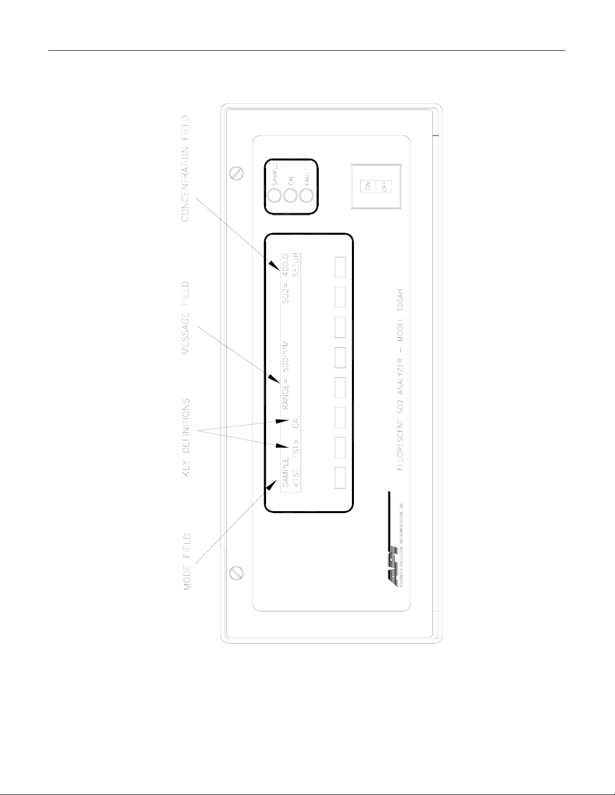
Figure 4-2: Front Panel Display
The display consists of 2 lines of 40 characters each (see Figure 4-2). The top line is divided into
3 fields, and displays information. The first field is the mode field. The mode field indicates the
current mode of the Analyzer. Usually, it shows "SAMPLE", indicating that the instrument is in
sample mode. The center field displays TEST values. The TEST functions allow you to quickly
access many important internal operating parameters of the M100AH. This provides a quick
check on the internal health of the instrument. The right hand field shows current concentration
value of SO
.
2
4.2.5.1 Front Panel Display
The second line of the display contains eight fields. Each field defines the key immediately
below it. By redefining the keys dynamically it is possible to simplify the instrument electronics
and user interface.
4.2.5.2 Status LED's
At the right of the display there are 3 status LED's. They can be in three states, OFF, ON, and
Blinking. The meanings of the LED's are given in Table 4-2.
4-6

Teledyne API Model 100AH SO2 Analyzer Instruction Manual, 02417, Rev. D
Table 4-2: Front Panel Status LED's
LED State Meaning
Green Off
On
Blinking
Yellow
Red Off
(1) This occurs and means during Calibration, DAS holdoff, Power-up Holdoff, and when in
Diagnostic mode.
Off
On
Blinking
Blinking
NOT monitoring, DAS disabled or inactive
Monitoring normally, taking DAS data
Monitoring, DAS in HOLDOFF mode (1)
Autocal disabled
Autocal enabled
Calibrating
No warnings exist
Warnings exist
4.2.5.3 Power Switch
The power switch has two functions. The rocker switch controls overall power to the instrument;
in addition it includes a circuit breaker. If attempts to power up the M100AH result in a circuit
breaker trip, the switch automatically returns to the off position, and the instrument will not
power up. If this occurs, consult troubleshooting section or factory.
4.2.6 Power Supply Module
The Power supply module (PSM) supplies AC and DC power to the rest of the instrument. It
consists of a 4 output linear DC power supply and a 15 volt switching supply. In addition, it
contains the switching circuitry to drive the DC operated valves and several switched AC loads
to operate the reaction cell and UV lamp.
4.2.7 Pneumatic System
In the basic analyzer, the sample enters through a 5-micron TFE filter element. The sample then
enters the flow control module and the reaction cell. The external pump pack is supplied as
standard equipment with the M100AH.
When the zero/span valve option is included, the sample passes through the valve manifold and
then enters the reaction cell. (See Section 6.)
Sample flow is controlled by a critical flow orifice. The orifice is protected by a 20-micron filter.
The orifice never needs adjustment. The critical flow orifice maintains precise volumetric flow
control as long as the down stream pressure of the orifice is maintained under critical pressure.
For example, at or near 14" (350 mm) Hg absolute at sea level.
4-7

Teledyne API Model 100AH SO2 Analyzer Instruction Manual, 02417, Rev. D
4.3 I/O Hardware Interface
4.3.1 RS-232 Interface
The M100AH uses the RS-232 communications protocol to allow the instrument to be connected
to a variety of computer based equipment. RS-232 has been used for many years and is well
documented. Generally, every manufacturer observes the signal and timing requirements of the
protocol very carefully.
Data Communications Software for a PC: You will need to purchase a software package so
your computer can transmit and receive on its serial port. There are many such programs, we use
PROCOMM at TELEDYNE API. Once you set up the variables in PROCOMM and your wiring
connections are correct, you will be able to communicate with the analyzer. Make sure the
analyzer is set up for 2400 baud (SETUP-MORE-COMM-BAUD) and that PROCOMM is set up
as described in the "RS-232 Pin Assignments" Figure 4-3.
4-8

Teledyne API Model 100AH SO2 Analyzer Instruction Manual, 02417, Rev. D
Figure 4-3: RS-232 Pin Assignments
4-9

Teledyne API Model 100AH SO2 Analyzer Instruction Manual, 02417, Rev. D
4.3.1.1 RS-232 Connection Examples
Example 1: Connecting the M100AH (using supplied cable) to an IBM-PC AT compatible
computer (DB-25 external connector, or DB-25 end of DB-9 to DB-25 Adapter).
In this case, the PC is wired as DTE and the analyzer is jumpers set as DCE, therefore a null
modem is not needed. The wiring is "straight through" i.e. pin 1 to pin 1, pin 2 to pin 2, etc.
Therefore all you have to do here is adapt the connector on the analyzer cable (male DB-25) to
the DB-25 male on the PC. A female to female DB-25 "gender changer" (cable or adapter) will
complete the connection. Make sure none of the adapters have null modems in them.
Example 2: Connecting the Teledyne API analyzer to a serial printer.
In this case, it will be necessary to determine whether the printer is DCE or DTE. Some printers
can be configured for either DCE or DTE by jumpers or DIP switch settings. Consult the user
manual for the printer. If the DB-25 connector pinout shows that data is output on pin 2 (from
the printer), then it is DTE and the TELEDYNE API analyzer should be switch set to DCE
mode. If pin 2 of the printer DB-25 is an input to the printer, then set the switch of the analyzer
to DTE mode. Refer to drawing #01916.
Example 3: Connecting the Teledyne API analyzer to a modem.
The modem is always configured as DCE. Therefore, setting switch as the DTE will be required
to connect the analyzer to the modem. Refer to drawing #01916.
4.3.1.2 RS-232 Diagnostic Procedures
There are several features of the M100AH to make connecting to RS-232 and diagnosing RS232 faults easier.
There are two LED's on the rear panel Connector Board that which are connected to pin 2 and 3
of the DB-9 connector on the board. If the switch is in the DCE position (default) the red LED is
connected to pin 3 of the DB-9 connector. When data is transmitted by the M100AH the red
LED will flicker, indicating data present on this line. When the M100AH is running, the LED
will normally be ON, indicating logic low. A one second burst of data can be transmitted over
the port by a command in the DIAGNOSTIC menu. Press SETUP-DIAG, scroll to select RS232
and press ENTR to transmit a burst of lower case "w"'s.
The green LED is connected to pin 2. If the switch is in the default DCE position, this is the pin
on which the M100AH receives data. It is ON if an outside device is connected. This LED gets
its power from the outside device. When data is being transmitted by the outside device to the
M100AH this LED will flicker.
When you are attempting to configure the RS-232 port, if either of the LED's go out when the
cable is connected, that generally means that there is a grounding problem. Check the relative
ground levels of pin 5 on the DB-9.
4-10

Teledyne API Model 100AH SO2 Analyzer Instruction Manual, 02417, Rev. D
4.3.2 Status Output Interface
The status output is a feature that reports the Analyzer conditions via contact closures on the rear
panel. The closures are available on a 50 pin connector on the rear panel. The contacts are NPN
transistors which can draw up to 50 mA of DC current. The pin assignments are listed in the
Table below.
Table 4-3: Status Output Pin Assignments
Output # PIN # Definition Condition
1 1 (-), 2 (+) ZERO CAL CLOSED IN ZERO CAL
2 3 (-), 4 (+) SPAN CAL CLOSED IN SPAN CAL
3 5 (-), 6 (+) FLOW ALARM CLOSED IF FLOW WARNING
4 7 (-), 8 (+) TEMP ALARM CLOSED IF ANY TEMP WARNING
5 9 (-), 10 (+) DIAG MODE CLOSED IN DIAG MODE
6 11 (-), 12 (+) POWER OK CLOSED IF SYSTEM POWER OK
7 21 (-), 22 (+) SYSTEM OK CLOSED IF SYSTEM OK
8 19 (-), 20 (+) HVPS ALARM CLOSED IF HVPS WARNING
9 13 (-), 14 (+) SPARE
10 23 (-), 24 (+) HIGH RANGE CLOSED IF HIGH PMT RANGE
11 25 (-), 26 (+) LOW SPAN CAL LOW SPAN CALIBRATION
12 27 (-), 28 (+) UV LAMP ALARM CLOSED IF UV LAMP WARNING
The Status/Temp Board schematic can be found in the Appendix Drawing 01087.
4-11

Teledyne API Model 100AH SO2 Analyzer Instruction Manual, 02417, Rev. D
Figure 4-4: Interfacing Contact Closure I/O
4-12

Teledyne API Model 100AH SO2 Analyzer Instruction Manual, 02417, Rev. D
4.3.3 Contact Closure Control Input Interface
The Zero/Span calibration can be initiated using external control inputs to control optional
Zero/Span valves. There are 4 optoisolator type control inputs available and each input is
assigned by the software for specific calibration control. Refer to Figure 2-2 REMOTE IN PIN
ASSIGNMENTS Table and Figure 4-4 for interfacing with external device. Refer to Section 8.5
for additional information.
Figure 4-4 shows an example of a control input interfacing circuit. The input current through the
LED is limited by a built-in resistor to prevent damage due to over-current. Once the desired
input channels are properly connected, the user can set up each input to perform specific
calibration. The input signal should be a high level (opto closed) with a minimum duration of 1
second.
4-13

Teledyne API Model 100AH SO2 Analyzer Instruction Manual, 02417, Rev. D
INTENTIONALLY BLANK
4-14

Teledyne API Model 100AH SO2 Analyzer Instruction Manual, 02417, Rev. D
5 SOFTWARE FEATURES
This section covers the software features of M100AH which is designed as a computer
controlled instrument. All major operations are controlled from the front panel display and
keyboard through a user friendly menu. Sample mode is explained for the basic operation of the
analyzer including calibration steps. Advanced software features are covered for experienced
users under the Setup mode offering advanced instrument control capabilities for optimum
operation of the instrument. See "Section 2 Getting Started" for installation and initial operation.
5.1 Index To Front Panel Menus
The next several pages contain two different styles of indexes that will allow you to navigate the
M100AH software menus. The first two pages show a "tree" menu structure to let you see at a
glance where each software feature is located in the menu. The second menu contains a brief
description of each key mnemonic and a reference to the section of the manual that describes its
purpose and function in detail.
5-1

Teledyne API Model 100AH SO2 Analyzer Instruction Manual, 02417, Rev. D
Figure 5-1: Sample Menu
Figure 5-2: Setup Menu Tree
5-2

Teledyne API Model 100AH SO2 Analyzer Instruction Manual, 02417, Rev. D
5.1.1 Sample Menu
Table 5-1: M100AH Sample Menu Structure
Menu Level
Level 1 Level 2 Level 3 Level 4 Description
TEST
TST>
CAL Zero/Span calibration w/ gas
LOW Shown if AUTO or DUAL
HIGH Shown if AUTO or DUAL
CALZ Zero calibration w/ zero gas
CALS Span calibration w/ span gas
ZERO Press ZERO then ENTR will
SPAN Press SPAN then ENTR will
Test functions 5.2.1,
through sample port
range selected for low span
calibration
range selected for high span
calibration
from zero valve option
from span valve option
zero analyzer
span analyzer
Reference
Section
Table 10-1
5.2.2.1, 8.1
5.2.2.3, 5.3.4
5.2.2.3, 5.3.4
5.2.2.2, 8.2, 8.3
5.2.2.3, 8.2, 8.3
5.2.2.2
5.2.2.3
LOW Low span gas calibration 5.2.2.3
HIGH High span gas calibration 5.2.2.3
CONC Expected SO2 span
concentration
SETUP The SETUP Menu - See next
table
5.2.2.4
Table 5-2
5-3

Teledyne API Model 100AH SO2 Analyzer Instruction Manual, 02417, Rev. D
5.1.2 Set-Up Menu
Table 5-2: M100AH Setup Menu Structure
Setup Menu #1
Level 1 Level 2 Level 3 Level 4 Description
CFG CFG is primarily used for
showing special
configuration options and
factory special software
PREV,
NEXT,
LIST
AUTOCAL Automatic zero/span check
SEQx Select SEQUENCE 1 thru
MODE Disable or enable zero
SET SETUP automatic
PREV, NEXT can be used
to scroll through the
configuration list
LIST automatically scrolls
the list
or calibration
3
and/or span mode
zero/sapn calibration
sequence
Reference
Section
5.3.1
5.3.1
5.3.2, 6.3
5.3.2, 6.3
5.3.2, 6.3
5.3.2, 6.3
DAS Data Acquisition System
(DAS) -
EDIT SETUP Data Acquisition
System (DAS)
VIEW PREV Examine the DAS data
buffer - display previous
average
PV10 Move UP previous 10
averages in the DAS data
buffer
NEXT Examine the DAS data
buffer - display next
average
NX10 Display next 10 averages in
the DAS data buffer
5.3.3
5.3.3
5.3.3
5.3.3
5.3.3
5.3.3
5-4

Teledyne API Model 100AH SO2 Analyzer Instruction Manual, 02417, Rev. D
Table 5-3: M100AH Menu Structure - Setup Menu #2
Setup Menu #2
Level 1 Level 2 Level 3 Level 4 Description
RNGE Range control menu 5.3.4
MODE Range mode select - Single,
Autorange, Dual
AUTO Automatically select output
range
DUAL Independent output ranges
for REC and DAS
SINGLE Single range for both REC
and DAS outputs
SET Sets range if mode is Single
range
LO Sets low range value if
Autorange enabled
HI Sets high range value if
Autorange enabled
UNITS Unit selection menu 5.3.4.4
PPM,
MGM
Select units that instrument
uses
Reference
Section
5.3.4
5.3.4
5.3.4
5.3.4
5.3.4.1
5.3.4.2
5.3.4.2
5.3.4.4
PASS Password enable/disable
menu
ON-OFF Enable/disable password
checking
CLOCK TIME Adjusts time on the internal
time of day clock
DATE Adjusts date on the internal
time of day clock
MORE Continue menu one MORE
level down
5.3.5
5.3.5
5.3.6
5.3.6
Table 5-4
5-5

Teledyne API Model 100AH SO2 Analyzer Instruction Manual, 02417, Rev. D
Table 5-4: M100AH Menu Structure - Setup Menu #3
Setup Menu #3
Level 1 Level 2 Level 3 Level 4 Description
MORE Next level of the SETUP
menu
COMM RS-232 communications
control menu
BAUD 300-
1200240048009600-
19.2k
ID Sets the instrument ID-
VARS Internal variables 5.3.9, 10.1.4
PREV,
NEXT,
JUMP,
EDIT
PREV, NEXT scroll up and
Set the BAUD rate to 3001200-2400-4800-9600-
19.2K
(included on all RS-232
messages)
down through the VARS
menu. Jump will go to
variable number selected,
EDIT will allow editing of
the selected variable.
Reference
Section
5.3.8
5.3.8, 7.1
5.3.8, 7.1.1
5.3.9, 10.1.4
DIAG Diagnostic menu 5.3.7, 10.1.3
PREV,
NEXT
PREV, NEXT scroll up and
down through the DIAG
menu. (SIGNAL I/O,
ANALOG OUTPUT, D/A
CALIBRATION, OPTIC
TEST, ELECTRICAL
TEST, LAMP
CALIBRATION, TEST
CHAN OUTPUT, RS-232
OUTPUT)
5.3.7, 10.1.3
5-6

Teledyne API Model 100AH SO2 Analyzer Instruction Manual, 02417, Rev. D
5.2 Sample Mode
5.2.1 Test Functions
NOTE
In any of the following TEST functions, if XXXX is displayed,
that indicates an off scale and therefore meaningless reading.
To use the TEST functions to diagnose instrument faults, refer to Troubleshooting Section 10.1.
Range
This is the range of the instrument. In standard configuration there is one range for both REC
and DAS outputs.
Dual range allows a different range for each output. When enabled, the RANGE test
measurement is replaced with two different test measurements, RANGE1 (LOW RANGE) and
RANGE2 (HIGH RANGE).
Auto range option allows a low range and high range. The M100AH will automatically switch to
the other range dynamically as concentration values require. The TEST values will show the
range the instrument is currently operating in, and will dynamically display the alternate range as
the range changes occur.
Stability
The instrument stability is used to indicate the stability of measurement of analyzer. It is
computed as the standard deviation of 25 samples of a moving window with interval of 10
seconds between each sample.
Sample Pressure
Sample pressure is measured using a solid state pressure sensor at the upstream of the flow
control module. This reading will vary according to the sample gas pressure, altitude and local
weather condition.
Vacuum Pressure
Sample pressure is measured at the downstream of the flow control module. This reading is the
reaction cell pressure which is used by the CPU to compensate the SO
pressure of the sample gas in the reaction cell.
concentration due to its
2
5-7

Teledyne API Model 100AH SO2 Analyzer Instruction Manual, 02417, Rev. D
Sample Flow
The sample flow is computed from the pressure measured upstream of the flow control module.
Since the downstream of the orifice is well within the critical pressure (which is also checked
continuously), it is the upstream pressure of the orifice responsible directly proportional to the
flow through the orifice. Flow variation has little effect on the analyzer reading. Its nominal
value is 650 ± 60 cc/min.
PMT Voltage
The PMT VOLTAGE measures the PMT signal at the output of the preamp board. The
waveform of the PMT voltage can be complex, and vary up to 5000 mV when a high
concentration of SO
is being measured. If the PMT reading is consistently 5000 mV, that
2
indicates an off-scale reading. Typical readings bounce around, which is normal.
UV Lamp
UV Lamp reading is the measurement voltage from the reference detector preamp board. Typical
value is between 2000 mV and 4000 mV and above 600 mV is acceptable.
Stray Light
Stray Light is the background light of the reaction cell expressed in PPM while sampling zero
gas. It is only an indication of the condition of the optical system such as lenses, UV filter, light
leak, etc.
Dark PMT
The dark current of the PMT is periodically measured to compensate any PMT dark current drift
and offset. Typical value is less than 200 mV.
Dark Lamp
This is the dark current of the UV reference detector which is used to compensate any dark
current drift and offset. This measurement is synchronized to the Dark PMT measurement
period. Typical value is less than 200 mV.
Slope
The coefficient of straight line equation (y = mx + b) determines the calibration of the M100AH.
The slope parameter (m) can be thought of as a gain term which determines the steepness of the
calibration curve. Typical value is 1 ± 0.3.
Offset
The offset parameter (b) compensates for differences in the background signal of the optical
system. Typical value is less than 100 mV.
5-8

Teledyne API Model 100AH SO2 Analyzer Instruction Manual, 02417, Rev. D
High Voltage Power Supply (HVPS)
The HVPS reading is a measure of the scaled-up HVPS programming voltage. The voltage used
to set the HVPS output is generated on the Preamp board. Its value is between 0 and 1 volt,
corresponding to a voltage of 0 to 1000 volts out of the HVPS. The HVPS front panel TEST
measurement will be typically around 450-650 V.
DC Power Supply (DCPS)
The DCPS voltage is a composite of the 5 and ± 15 VDC voltages in the Power Supply Module.
This is meant to be a quick indicator to show if the PSM is working correctly. The nominal value
is 2500 mV ± 200 mV.
Reaction Cell Temperature
This is a measurement of the temperature of the reaction cell. It is controlled by the computer to
50 ± 1°C. Temperatures outside this range will cause the M100AH output to drift.
Box Temperature
This TEST function measures the temperature inside the chassis of the M100AH. The temperature
sensor is located on the Status/Temp Board. Typically it runs 2 to 10°C higher than the ambient
temperature. The M100AH has been engineered to operate over 5 to 40°C ambient temperature
range.
PMT Temperature
The temperature of the PMT is closely controlled by a dedicated proportional temperature controller.
The nominal set-point is 7 ± 1°C. Readings outside this range will cause instrument drift due to gain
changes in the PMT detector.
Time
This is an output of the M100AH's internal time of day clock.
5-9

Teledyne API Model 100AH SO2 Analyzer Instruction Manual, 02417, Rev. D
5.2.2 CAL, CALS, CALZ, Calibration Functions
The calibration and zero/span checking of the M100AH analyzer is treated in detail in Section 8.
Table 8-1 summarizes types of calibration.
5.2.2.1 CAL, CALS, CALZ
The CAL, CALS, and CALZ keys control the calibration functions of the analyzer. In the CAL
mode the analyzer can be calibrated with zero/span gas coming in through the sample filter
assembly on the rear panel. If the instrument will be used on more than one range such as AUTO
RANGE or DUAL RANGE, it should be calibrated separately on each applicable range (see
Section 5.3.4 and 8.1 for calibration procedure).
If the analyzer is equipped with the optional Zero/Span valves, there will also be CALZ and
CALS buttons. The setup of this option is covered in Section 6.3, and operation is explained in
Section 8.2.
5.2.2.2 Zero
Pressing the ZERO key along with ENTR will cause the instrument to adjust the OFFSET value
of the internal formula so that the instrument reads zero. The M100AH allows zero adjustment
over a limited range of signal levels mostly due to the background signal, therefore the signal
does not have to be exactly zero for the instrument to do a zero cal. The instrument will not,
however, allow a zero cal on any signal level, therefore it is not possible to zero the instrument
with span gas in the reaction cell. If the ZERO key does not come on as expected, check
Section 10.2.9.
5.2.2.3 Span
Pressing the SPAN key along with ENTR will cause the instrument to adjust the SLOPE value of
the internal formula so the instrument displays the span value. The expected SO
span
2
concentration must be entered before doing a SPAN calibration. See Table 8-3.
Like the Zero calibration, the Span cal cannot be done with any concentration of span gas. If the
signal level is outside certain limits, the SPAN key will not be illuminated. If you encounter this
condition see Section 10.2.8. It is also possible at low levels of span concentration that both the
ZERO and SPAN keys might be on, thus allowing you to either zero or span the instrument. In
this case, care must be taken to perform the correct operation or the analyzer can become miscalibrated.
5-10

Teledyne API Model 100AH SO2 Analyzer Instruction Manual, 02417, Rev. D
5.2.2.4 SO2 Cal Concentration
Before the M100AH can be spanned, it is necessary to enter the expected span concentrations for
SO2. This is done by using CAL-CONC. Concentration values from 10 to 4500 PPM are
accepted. If a value of XXXX is displayed, that indicates an offscale, or invalid reading. The
XXXX value will often be displayed at power-up when there is no data yet available to be
displayed. Certain instrument fault conditions will cause X's to be displayed. This is the same as
the needle being offscale on a analog meter. See the Troubleshooting Section 10.2.8 if this
occurs.
5.2.2.5 Formula Values
The slope and offset terms should be checked after each calibration. The values for these terms
contain important information about the internal health of the analyzer.
To compute the SO
concentration, the formula for a straight line is used.
2
y = mx + b
Where:
y = the SO
concentration
2
m = the slope
x = the conditioned PMT tube output
b = the offset
In comparison with analog analyzers the slope term is equivalent to the "span pot" and the b term
is equivalent to the "zero pot". Again, like an analog analyzer, there is only a limited range of
adjustment allowed for either term, and there are consequences of having the values near the
high or low limits of their respective ranges.
The x term is the conditioned PMT signal. PMT signal is adjusted for the lamp ratio background,
range, temperature, and pressure.
The offset (b) term is the total background light with the zero term subtracted out. The zero term
measures detector dark current and amplifier noise. The b term is composed mostly of the optical
system background.
5-11

Teledyne API Model 100AH SO2 Analyzer Instruction Manual, 02417, Rev. D
5.3 Set-Up Mode
5.3.1 Configuration Information (CFG)
This menu item will tell if the installed software has factory special features or other nonstandard features. If you call Teledyne API service, you may be asked for information from this
menu.
5.3.2 Automatic Calibration (AutoCal)
The AutoCal feature allows the M100AH to automatically operate the Zero/Span Valve option
ON on a timed basis to check or adjust its calibration. This menu item is shown only if the
Zero/Span Valve option is installed. Detailed information on setting up AutoCal is found in the
Section 6.3.
5.3.3 Data Acquisition System (DAS)
The Model 100AH contains a flexible and powerful built in data acquisition system (DAS) that
enables the analyzer to store concentration data as well as many diagnostic parameters in its
battery backed memory. This information can be viewed from the front panel or printed out
through the RS-232 port. The diagnostic data can be used for performing “Predictive
Diagnostics” and trending to determine when maintenance and servicing will be required.
The logged parameters are stored in what are called “Data Channels.” Each Data Channel can
store multiple data parameters. The Data Channels can be programmed and customized from the
front panel. A set of default Data Channels has been included in the Model 100AH software.
These are described Section 5.3.3.1. For more information on programming custom Data
Channels, a supplementary document containing this information can be requested from
Teledyne API.
5.3.3.1 Data Channels
The function of the Data Channels is to store, report, and view data from the analyzer. The data
may consist of SO
output.
The M100AH comes pre-programmed with a set of useful Data Channels for logging SO
concentration and predictive diagnostic data. The default Data Channels can be used as they are,
or they can be changed by the user to fit a specific application. They can also be deleted to make
room for custom user-programmed Data Channels.
concentration, or may be diagnostic data, such as the sample flow or PMT
2
2
5-12

Teledyne API Model 100AH SO2 Analyzer Instruction Manual, 02417, Rev. D
The data in the default Data Channels can be viewed through the SETUP-DAS-VIEW menu.
Use the PREV and NEXT buttons to scroll through the Data Channels and press VIEW to view
the data. The last record in the Data Channel is shown. Pressing PREV and NEXT will scroll
through the records one at a time. Pressing NX10 and PV10 will move forward or backward 10
records. For Data Channels that log more than one parameter, such as PNUMTC, buttons labeled
<PRM and PRM> will appear. These buttons are used to scroll through the parameters located
in each record.
The function of each of the default Data Channels is described below:
CONC:
PNUMTC:
CALDAT:
Samples SO
concentration at one minute intervals and stores an average every
2
hour with a time and date stamp. Readings during calibration and calibration
hold off are not included in the data. The last 800 hourly averages are stored.
Collects sample flow and sample pressure data at five minute intervals and
stores an average once a day with a time and date stamp. This data is useful for
monitoring the condition of the pump and critical flow orifice (sample flow)
and the sample filter (clogging indicated by a drop in sample pressure) over
time to predict when maintenance will be required. The last 360 daily averages
(about 1 year) are stored.
Logs new slope and offset every time a zero or span calibration is performed.
This Data Channel also records the instrument reading just prior to performing
a calibration.
NOTE: This Data Channel collects data based on an event (a calibration) rather
than a timer. This Data Channel will store data from the last 200 calibrations.
This does not represent any specific length of time since it is dependent on how
often calibrations are performed. As with all Data Channels, a time and date
stamp is recorded for every data point logged.
5-13

Teledyne API Model 100AH SO2 Analyzer Instruction Manual, 02417, Rev. D
5.3.3.2 RS-232 Reporting
Automatic RS-232 reporting can be independently enabled and disabled for each Data Channel.
For all default data channels, RS-232 reporting is initially set to “OFF.” If this property is turned
on, the Data Channel will issue a report with a time and date stamp to the RS-232 port every
time a data point is logged. The report format is shown below:
D 31:10:06 0412 CONC : AVG CONC1=6.8 PPM
The report consists of the letter “D” follow by a time/date stamp (“31:10:06”) followed by the
instrument ID number (“0412”). Next is the Data Channel name (“CONC”) and the sampling
mode (“AVG” indicates that the data point is an average of more than one sample as opposed to
a instantaneous reading, “INST”). Finally, the name of the parameter and its value
(“CONC1=6.8 PPM”) are printed. For Data Channels that sample more than one parameter, such
as PNUMTC and CALDAT, each parameter is printed on a separate line.
To enable RS-232 reporting for a specific Data Channel:
Step Action Comment
1.
2.
3.
4.
5.
6.
7.
8.
Press SETUP-DAS-
EDIT-ENTR
Press PREV/NEXT
Press EDIT
Press SET> (5 times)
Press EDIT
Toggle OFF to ON
Press ENTR
Press EXIT (4 times)
Enter DAS menu to edit Data Channels
Select Data Channel to edit
Edit selected Data Channel
Scroll through setup properties until RS-232 REPORT:
OFF is displayed
Edit selected setup property
Change RS-232 REPORT property
Accepts change
Exits back to sample menu
See Section 7.7 for more information on DAS reporting through the RS-232 interface.
5-14

Teledyne API Model 100AH SO2 Analyzer Instruction Manual, 02417, Rev. D
5.3.4 Range Menu
The instrument operates on any full scale range from 10 to 5000 PPM. The range is the
concentration value that equals the maximum current (or voltage) output on the rear panel of the
instrument.
If the range you select is between 10 and 500 PPM the front panel display will read the
concentration anywhere from 0 to 500 PPM regardless of the range selected, however the analog
output is scaled for the range selected. If the range selected is from 501 to 5000 PPM the front
panel display will read from 0 to 5,000 PPM. The M100AH has 2 internal hardware gain
settings, namely 0-500 PPM (gain of 10) and 0-5000 PPM (gain of 1). If the physical gain
changes, then the test measurement readings such as PMT and OFFSET will be adjusted
accordingly.
NOTE
If the instrument will be used on more than one range such as AUTO
RANGE or DUAL RANGE, it should be calibrated separately on each
applicable range (see Section 8.6 for calibration procedure).
Each 4-20 mA current output channel should be connected to one interfacing device only.
There are 3 range choices: only one of the following range choices can be active at any one time.
1. Single Range; two analog outputs are fixed to a single range.
2. Auto Range; both analog outputs are automatically set for low or high range.
3. Dual Ranges; each of an analog output ranges can be set differently.
5.3.4.1 Single Range
This range option selects a single range for both output channels (REC, DAS) of the M100AH.
To select Single Range press SETUP-RNGE-MODE-SING, then press ENTR. To set the value
for the range press SETUP-RNGE-SET, and enter the full scale range desired from 10 PPM to
5000 PPM, then press ENTR.
5-15

Teledyne API Model 100AH SO2 Analyzer Instruction Manual, 02417, Rev. D
5.3.4.2 Auto Range
Auto Range allows output range to automatically range between a low value (RANGE1) and a
higher value (RANGE2). When the instrument output increases to 98% of the low range value, it
will Auto Range into Hi range. In Hi range, when the output decreases to 75% of low range, it
will change to the lower range. There is only one low range and one high range for all outputs.
The Hi range mode is signaled by a bit on the STATUS option, see Table 4-3. If you select a Hi
range that is less than Low range, the M100AH will remain locked in Low range and behave as a
Single Range instrument.
To set up Auto Range press SETUP-RNGE-MODE-AUTO, then press ENTR. To set the values
press SETUP-RNGE-SET. The M100AH will prompt you for Low Range, then Hi Range which
is the lower and upper ranges of Auto Range. Key in the values desired, then press ENTR.
Once desired range is selected, then M100AH should be calibrated for each range entered. (Refer
Section 8.6 for Calibration Procedure.)
5.3.4.3 Dual Ranges
Dual Ranges allows you to select different ranges for REC and DAS analog output channels. To
set up Dual Ranges press SETUP-RNGE-MODE-DUAL, then press ENTR. To set the values
press SETUP-RNGE-SET. The M100AH will prompt you for the range of RANGE1 (REC) and
RANGE2 (DAS) outputs (refer to Figure 2-2 for corresponding analog output terminals). Key in
the desired range for each output channel, then press ENTR after each value.
If Dual Range is selected and their desired ranges are entered accordingly, the M100AH should
be calibrated for each of the range selected. See Section 8.6 for Calibration Procedure.
If user has selected either Auto Range or Dual Range, then pressing CAL button will cause to
display LOW RANGE (RANGE 1) and HI RANGE (RANGE 2). Select desired range number
and press ENTR to continue calibration procedure of selected range. Under each range
calibration procedure, the M100AH will display separate test measurement functions
accordingly to show the Slope, Offset, Range, etc. However once exit this calibration menu and
return to the main menu (see Figure 2-4), then the test measurement parameters for LOW
RANGE (RANGE1) are used throughout the M100AH.
5-16

Teledyne API Model 100AH SO2 Analyzer Instruction Manual, 02417, Rev. D
5.3.4.4 Concentration Units
The M100AH can display concentrations in PPM, mg/m3. Coefficients for mg/m3 were based on
0°C (25°C for U.S.EPA), 760 mmHg. Different pressure and temperature can be used by
adjusting values entered for calibration gas to read the correct concentration at the conditions
being used. This adjustment is not needed if units are within the same type.
To change the current units press SETUP-RNGE-UNIT from the SAMPLE mode and select the
desired units.
CAUTION
If the current units are in PPM and the span value is 400 PPM, and
the units are change to mg/m3 the span value is NOT re-calculated to
the equivalent value in mg/m3. Therefore the span value now becomes
400 mg/m3 instead of 400 PPM. Use the following equation to convert
the unit with proper temperature and pressure adjustments. Then
recalibrate the analyzer.
mmHg
SO in ppm
22
286
.
×× × =
273
T
760
o
K
P
SO in
mg
m
3
NOTE
You should now re-enter the expected span concentration value in
different units which should be adjusted for proper pressure and
temperature (25°C for U.S. EPA) in the new units and re-calibrate
the instrument using one of the methods in Section 8.
Changing units affects all of the RS-232 values, all of the display
values, and all of the calibration values and therefore you must
re-calibrate the Analyzer.
5-17

Teledyne API Model 100AH SO2 Analyzer Instruction Manual, 02417, Rev. D
5.3.5 Password Enable
There are two levels of password protection. The most restrictive level requires a password to do
instrument calibration. The second level requires a password to do SETUP functions.
If both password levels are turned off, no passwords are required, except in the VARS menu
where a password is always required. To enable password press SETUP-PASS-ON. A list of
passwords is in Table 5-5.
Table 5-5: Calibrate, Setup Passwords
Password Usage Password
Calibration Password Use to get into CAL menus 512
Setup Password Use to get into SETUP menus 818
5.3.6 Time of Day Clock
The instrument has an internal time of day clock. The time of day can be set by pressing SETUPCLOCK-TIME and entering the time in 24hr format. In a similar manner the date can be entered
by pressing SETUP-CLOCK-DATE and entering the date in a DD-MM-YY format. If you are
having trouble with the clock running slow or fast, the speed of the clock can be adjusted by
selecting the CLOCK_ADJ variable in the SETUP-MORE-VARS menu (See Section 10.1.4).
5.3.7 Diagnostic Mode
The M100AH Diagnostic Mode allows additional tests and calibrations of the instrument. These
features are separate from the TEST functions because each DIAG function has the ability to
alter or disable the output of the instrument. While in DIAG mode no data is placed in the DAS
averages. Details on the use of Diagnostic mode are in Section 10.1.3.
5.3.8 Communications Menu
The COMM menu allows the RS-232 BAUD rate to be set. To set the BAUD rate press SETUPMORE-COMM-BAUD, select the appropriate BAUD rate, then press ENTR.
The instrument ID number can also be set. This ID number is attached to every RS-232 message
sent by the M100AH. To set the ID press SETUP-MORE-COMM-ID and enter a 4 digit number
from 0000-9999, then press ENTR.
5-18

Teledyne API Model 100AH SO2 Analyzer Instruction Manual, 02417, Rev. D
5.3.9 Variables Menu (VARS)
This menu enables you to change the settings on certain internal variables. The VARS
Table 10-5 is located in the Troubleshooting Section 10.1.4.
CAUTION
Before changing the settings on any variables, make sure you
understand the consequences of the change. The variables should only
be changed by skilled maintenance people since they can potentially
interfere with the performance of the Analyzer.
5-19

Teledyne API Model 100AH SO2 Analyzer Instruction Manual, 02417, Rev. D
INTENTIONALLY BLANK
5-20

Teledyne API Model 100AH SO2 Analyzer Instruction Manual, 02417, Rev. D
6 OPTIONAL HARDWARE AND SOFTWARE
Optional equipment offered with the M100AH includes:
1. Rack mount with slides (P/N 00280)
2. Rack mount without slides, ears only (P/N 01470)
3. Zero/Span valves assembly (P/N 0178603)
4. 4-20mA, isolated outputs (P/N 01471)
6.1 Rack Mount Options
The Rack Mount option including slides and ears, permits the Analyzer to be mounted in a
standard 19" wide x 24" deep RETMA rack. The Rack Mount option can also be ordered without
slides for applications requiring the instrument to be rigidly mounted in a RETMA rack.
6.2 Zero/Span Valves
The Zero/Span Valve option consists of a manifold with four valves. See Figure 2-5 for valve
location. Connections are provided on the rear panel for two (low and high) span gas and zero
gas inputs to the valves (See Figure 2-2). These valves can be actuated by several methods
shown in Table 6-1.
Table 6-1: Zero/Span Valve Operation
Mode Description Reference Section
1. Front panel operation via
CALS and CALZ
buttons.
2. Automatic operation
using AUTOCAL
3. Remote operation using
the RS-232 interface
4. Remote operation using
external contact closures
Calibration Section 8 - Manual Zero/Span Check.
Setup and use of AUTOCAL is described in Table 6-2,
and Section 8.3.
Setup described in Table 7-1. Operation of AUTOCAL
described in Section 6.3 and Section 7.5.
Section 8.5 - Automatic operation using external contact
closures. Table 8-7.
6-1

Teledyne API Model 100AH SO2 Analyzer Instruction Manual, 02417, Rev. D
Zero/Span valves have 4 operational states:
1. Sample mode. All four valves are not energized and sample gas passes through the sample
valve and into the analyzer for analysis. For any other mode, sample valve is energized to
shut off sample port. Refer to Figure 9-3 Pneumatic Diagram.
2. Zero mode. The zero valve is energized allowing zero gas to be admitted into the analyzer
through the rear panel bulkhead fitting.
3. Low Span mode. The low span valve is energized and low span gas is admitted into the
analyzer through a rear panel bulkhead fitting.
4. High Span mode. The high span valve is energized and high span gas is admitted into the
analyzer through a rear panel bulkhead fitting.
Zero air and span gas inlets should supply their respective gases in excess of the 700 cc/min (i.e.
1000 cc/min) demand of the analyzer at ambient pressure. Ideally the calibration gas pressure
should be the same one as the sample gas pressure and should not differ more than 2 in-Hg.
Supply and vent lines should be of sufficient length and diameter to prevent back diffusion and
pressure effects. See Figure 2-3 for fitting location and tubing recommendations.
Adequate inexpensive zero air can be supplied from the room air by connecting a charcoal
scrubber and 5 micron particulate filter (Teledyne API P/N 000369) to the zero air inlet tubing.
The zero air scrubber used in conjunction with the Zero/Span Valve option provides an
inexpensive source of zero air.
6.3 Autocal - Setup Zero/Span Valves
The Zero/Span valves system can be set up to operate automatically on a timed basis. The
Teledyne API model 100AH with Zero/Span valves option offers capability to check any
combination of zero and up to two span points either automatically on a timed basis, through
remote RS-232 operation (see Section 7.5), or external contact closure (see Section 8.5).
There are three auto-calibration sequences called SEQ1, SEQ2, and SEQ3. Each SEQ can be
programmed to perform a specific calibration sequence. Under each SEQ, there are five
parameters that affect zero/span checking: the mode enable/selection, the starting date and time
of the calibration, the number of delay days and time, duration of calibration, and calibration
adjust enable/disable.
6-2

Teledyne API Model 100AH SO2 Analyzer Instruction Manual, 02417, Rev. D
1. Calibration Sequence Mode
Each sequence can generate any one of 7 different combinations of ZERO, LO, or HI span point.
Press SETUP-ACAL, and scroll up or down to select the desired sequence number (SEQx).
Press MODE and scroll up or down by pressing PREV or NEXT. Select one of the combination
shown below and press ENTR.
Combinations:
1) DISABLED; will disable corresponding SEQx setup.
2) ZERO
3) ZERO-LO
4) ZERO-HI
5) ZERO-LO-HI
6) LO
7) HI
8) LO-HI
2. Setup Calibration Timer:
Press SETUP-ACAL-SET to setup or edit the automatic calibration timer.
Following table summarizes the setup procedures:
Table 6-2: Setup Automatic Zero/Span Calibration
Default Description
Timer Enable ON Enable or disable automatic calibration timer.
Starting Date 01-JAN-95 MM:DD:YY
Starting Time 00:00 HH:MM, 0 - 23 hours and 0 - 59 minutes
Delta Days 1 Delay days between each calibration
(0 - 365 days)
Delta Time 00:00 HH:MM, 0 - 23 hours and 0 - 59 minutes
Duration 15.0 minutes 1 - 60.0 minutes
Calibrate OFF on/off. If ON is selected, it will adjust the
calibration.
The Timer Enable can be set to “OFF” to disable the automatic calibration timer while the
remote RS-232 calibration of specific sequence can be initiated.
6-3

Teledyne API Model 100AH SO2 Analyzer Instruction Manual, 02417, Rev. D
NOTE
Avoid setting two or more sequences at the same time of the day. Any new
sequence which is initiated whether from a timer, the RS-232, or the contact
closure inputs will override any sequence that is in progress.
The programmed start time must be a minimum of 5 minutes
later than the real time clock.
Examples of possible sequences are as following under any one of three available SEQx.
Example 1: To perform zero-span calibration check once per day at 10:30 PM, 5/20/97.
1) MODE: ZERO-HI
2) TIMER ENABLE: ON
3) STARTING DATE: 5/20/97
4) STARTING TIME: 22:30
5) DELTA DAYS: 1
6) DELTA TIME: 00:00
7) DURATION: 15.0 MINUTES
8) CALIBRATE: OFF
Example 2: To perform zero calibration adjust once per day retarding 15 minutes everyday starting
at 11:30 pm, 5/20/97.
1) MODE: ZERO
2) TIMER ENABLE: ON
3) STARTING DATE: 5/20/97
4) STARTING TIME: 23:30
5) DELTA DAYS: 0
6) DELTA TIME: 23:45
7) DURATION: 15.0 MINUTES
8) CALIBRATE: ON
6-4

Teledyne API Model 100AH SO2 Analyzer Instruction Manual, 02417, Rev. D
Example 3: To perform zero-span calibration check once per day at 10:30 PM and zero calibration
adjust once per week starting at 11:30 PM, 5/20/97.
1. Select any one of SEQx and setup as example 1 above.
2. Select any other SEQx and program as follows. Always avoid setting two or more sequences
at the same time of the day.
1) MODE: ZERO
2) TIMER ENABLE: ON
3) STARTING DATE: 5/20/97
4) STARTING TIME: 23:30
5) DELTA DAYS: 7
6) DELTA TIME: 00:00
7) DURATION: 15.0 MINUTES
8) CALIBRATE: ON
6-5

Teledyne API Model 100AH SO2 Analyzer Instruction Manual, 02417, Rev. D
6.4 4-20 mA, Isolated Current Loop Output
The standard non-isolated 4-20 mA current output provides current output capability by sharing the
common electrical ground. The optional current output offers to isolate the electrical ground from
the external ground of the interfacing device. The setup and operation is identical to the non-isolated
current output. See Troubleshooting Section 10 for electrical calibration procedure and refer to
drawings 01087 and 01248 for the jumper settings. Depending on the jumper setting, it can be used
for the current output or the voltage output.
NOTE
Each 4-20 mA current output should be connected to one
interfacing device only.
6-6

Teledyne API Model 100AH SO2 Analyzer Instruction Manual, 02417, Rev. D
7 RS-232 INTERFACE
The RS-232 communications protocol allows the instrument to be connected to a wide variety of
computer based equipment. The interface provides two basic functions in the M100AH.
1. First is a comprehensive command interface for operating and diagnosing the analyzer. This
interface has in fact more capabilities than the front panel keyboard.
2. The interface can provide an audit trail of analyzer events. In this function the port sends out
messages about instrument events like calibration or warning messages. If these messages are
captured on a printer or remote computer, they provide a continuous audit trail of the
analyzers operation and status.
7.1 Setting Up the RS-232 Interface
The baud rate is set from the front panel by SETUP-MORE-COMM-BAUD. Select the baud rate
appropriate for your application, 300, 1200, 2400, 4800, 9600, 19.2K. It is important to note
that the interfacing device must have identical settings in order for the communications to
work correctly.
Second is physical wiring of the analyzer to the other unit. We have incorporated into the
analyzer LED's that signal the presence of data on the communications lines, and also jumper
blocks to easily re-configure the analyzer from DCE to DTE if necessary (see drawing #01917).
In addition the front panel diagnostics allow test data streams to be sent out of the port on
command. This flexibility and diagnostic capability should simplify attaching our equipment to
other computers or printers. If problems occur, see the Section 4.3.1.2.
7.1.1 Setup from the Front Panel
There are 2 additional RS-232 setups that can be done via the front panel.
1. Set the Instrument ID number by SETUP-MORE-COMM-ID, and enter a 4 digit number
from 0000-9999. This ID number is part of every message transmitted from the port.
2. Set the RS-232 mode bit field in the VARS menu. To get to the variable press, SETUPMORE-VARS-ENTR and scroll to RS232_MODE, then press EDIT. The possible values
are:
7-1

Teledyne API Model 100AH SO2 Analyzer Instruction Manual, 02417, Rev. D
Table 7-1: RS-232 Port Setup - Front Panel
Decimal Value Description
1 Turns on quiet mode (messages suppressed)
2 Places analyzer in computer mode (no echo of chars)
4 Enables Security Features (Logon, Logoff)
8 Enables RS-232 menus display on M100AH front panel display
16 Enables alternate protocol (i.e. Hessen) and setup menu
32 Enables multi-drop support for RTS
NOTE
To enter the correct value, ADD the decimal values of the features you want
to enable. For example if LOGON and front panel RS-232 menus were
desires the value entered would be 4 + 8 = 12.
7.1.2 Security Feature
The RS-232 port is often connected to a public telephone line which could compromise
instrument security. If the LOGON feature is implemented the port has the following attributes:
1. A password is required before the port will operate.
2. If the port is inactive for 1 hour, it will automatically LOGOUT.
3. If not logged on, the only command that is active is the '?'. If this command is issued the
M100AH will respond with MUST LOG ON.
4. The following messages will be given at logon.
A. LOG ON SUCCESSFUL - Correct password given
B. LOG ON FAILED - Password not given or incorrect
C. LOG OFF SUCCESSFUL - Logged off
7-2

Teledyne API Model 100AH SO2 Analyzer Instruction Manual, 02417, Rev. D
The RS-232 LOGON feature must be enabled from the front panel by setting bit 4. See
Table 7-1. Once the feature is enabled, to logon type:
LOGON 940331
940331 is the default password. The password can be changed to any number from 0 to 999999
by the variable RS232_PASS. To change the password enter the command
V RS232_PASS=xxxxxx
which sets the password to the value xxxxxx.
7.1.3 Protocol of Port Communication
The RS-232 interface has two protocols of communication, because if the port is attached to a
computer it needs to have different characteristics than if used interactively. Consequently, there
are two primary styles of operation: terminal mode and computer mode.
When an operator is communicating with the analyzer via a terminal, the analyzer should be
placed into TERMINAL MODE, which echoes keystrokes, allows editing of the command line
using the backspace and escape keys, and allows recall of the previous command. When a host
computer or data logger is connected to the analyzer, it should be placed into COMPUTER
MODE, which does not echo characters received or allow the special editing keys.
Table 7-2: RS-232 Switching From Terminal Mode to Computer Mode
Key Function
Control-T (ASCII 20 decimal) Switch to terminal mode (echo, edit)
Control-C (ASCII 3 decimal) Switch to computer mode (no echo, no edit)
If the command line doesn't seem to respond to keystrokes or commands, one of the first things
you should do is send a Control-T to switch the command line interface into terminal mode.
Also, some communication programs remove CTRL-T and CTRL-C characters from the byte
stream, therefore these characters will not be sent to the analyzer. Check your communications
program owners manual.
7-3

Teledyne API Model 100AH SO2 Analyzer Instruction Manual, 02417, Rev. D
7.1.4 Entering Commands in Terminal Mode
In terminal mode, all commands must be terminated by a carriage return; commands are not
processed until a carriage return is entered. While entering a command you may use the
following editing keys:
Table 7-3: RS-232 Terminal Mode Editing Keys
Key Function
CR (carriage return) Execute command
BS (backspace) Backspace one character to the left
ESC (escape) Erase entire line
Control-R (ASCII 18 decimal) Recall previous command
Control-E (ASCII 5 decimal) Recall and execute previous command
Commands are not case-sensitive; you should separate all command elements (i.e. keywords,
data values, etc.) by spaces.
Words such as T, SET, LIST, etc. are called keywords and are shown on the help screen in
uppercase, but they are not case-sensitive. You must type the entire keyword; abbreviations are
not accepted.
OBTAINING HELP
Typing “?” followed by Return or Enter will cause a
help screen to be displayed.
7-4

Teledyne API Model 100AH SO2 Analyzer Instruction Manual, 02417, Rev. D
7.2 Command Summary
The information contained in the rest of this section covers all of the normal commands that are
required to operate the instrument from a remote terminal. If you are going to be writing
computer programs to communicate with the M100AH (i.e., operating the port in COMPUTER
MODE) we suggest that you order a supplementary manual "The RS-232 Interface", Teledyne
API part number 01350. This manual shows additional features of the port designed to support a
computer driven interface program.
There are 6 different types of messages output by the M100AH. They are grouped below by type
in Table 7-4, Table 7-5, and Table 7-6. The meanings of the various messages are discussed
elsewhere in the manual. The TEST, DIAGNOSTIC and WARNING messages are discussed in
Section 10.1, 10.2. DAS and VARIABLES are discussed in Section 5.3.3 and 5.3.9.
CALIBRATE is discussed in Section 8.
Table 7-4: RS-232 Interface Command Types
First Character Message Type
C Calibration status
D Diagnostic
R DAS report
T Test measurement
V Variable
W Warning
7-5

Teledyne API Model 100AH SO2 Analyzer Instruction Manual, 02417, Rev. D
Table 7-5: RS-232 Command Summary
Commands Definition
? Print help screen
T SET ALL Enable display of all test variables during T LIST
T SET name Display only NAME during T LIST
T LIST [ALL] Print all test variables enabled with T SET or ALL
warnings
T name Print single test, "name" from Table 7-7
T CLEAR ALL Disable T LIST, use with T SET name
W SET ALL Enable display of all warnings during W LIST
W LIST [ALL] Print warnings enabled with W SET or ALL warnings
W name Print individual "name" warning from Table 7-8
W CLEAR ALL Disable W LIST, use with W SET
C command Execute calibration "command" from Table 7-10
D LIST Prints all I/O signal values
D name Prints single I/O signal value/state
D name=value Sets variable to new "value"
D LIST NAMES Lists diagnostic test names
D ENTER name Enters and starts 'name' diagnostic test
D EXIT Exits diagnostic mode
D RESET Resets analyzer (same as power-on)
D RESET RAM System reset, plus erases RAM. Initializes DAS, SO2
concentration readings, calibration not affected.
D RESET EEPROM System reset, plus erases EEPROM (RAM_RESET
actions + setup variables, calibration to default values)
V LIST Print all easy variable names from Table 10-5
V name Print individual "name" variable
V name=value Sets variable to new "value"
V CONFIG Print analyzer configuration
7-6

Teledyne API Model 100AH SO2 Analyzer Instruction Manual, 02417, Rev. D
Table 7-6: RS-232 Command Summary
Terminal Mode Editing Keys Definition
V MODE Print current analyzer mode
BS Backspace
EXC Erase line
^R Recall last command
^E Execute last command
CR Execute command
^C Switch to computer mode
Computer Mode Editing Keys Definition
LF Execute command
^T Switch to terminal mode
Security Features Definition
LOGON password Establish connection to analyzer
LOGOFF Disconnect from analyzer
General Output Message Format
Reporting of status messages for use as an audit trail is one of the two principal uses for the RS232 interface. You can effectively disable the asynchronous reporting feature by setting the
interface to quiet mode. All messages output from the analyzer (including those output in
response to a command line request) have the format:
X DDD:HH:MM IIII MESSAGE
X is a character indicating the message type, as shown in the following table.
DDD:HH:MM is a time-stamp indicating the day-of-year (DDD) as a number from 1 to 366, the
hour of the day (HH) as a number from 00 to 23, and the minute (MM) as a number from 00 to
59.
IIII is the 4-digit machine ID number.
MESSAGE contains warning messages, test measurements, DAS reports, variable values, etc.
The uniform nature of the output messages makes it easy for a host computer to parse them.
7-7

Teledyne API Model 100AH SO2 Analyzer Instruction Manual, 02417, Rev. D
7.3 TEST Commands and Messages
Table 7-7: RS-232 Test Messages
Name Message Description
RANGE1 RANGE=xxxxx PPM2 Analyzer range
STABILITY STABIL=xxxx.x PPM Std. Deviation of last 25 SO2
concentration values
VACUUM PRES=xxx.x IN-HG-A Reaction cell pressure
SAMPPRESS PRES=xxx.x IN-HG-A Sample pressure
SAMPFLOW SAMPLE FL=xxx
Sample flow rate
CC/M
PMTDET PMT=xxxxxx MV PMT output
UVDET UV LAMP=xxxx MV Instantaneous UV lamp reading
LAMPRATIO LAMP RATIO=xx.x% Ratio of UV lamp reading to calibrated
UV lamp reading
STRAYLIGHT STR LGT=xxx.x PPM Stray light level
DARKPMT DRK PMT=xx.x MV PMT dark current in MV
DARKLAMP DRK LMP=xx.x MV UV detector dark current in MV
SLOPE SLOPE=x.xxx Calibration slope parameter
OFFSET OFFSET=xxx.x MV Calibration offset parameter
HVPS HVPS=xxxxx V High voltage power supply
DCPS DCPS=xxxxxx MV DC power supply
RCELLTEMP RCELL TEMP=xxx C Reaction cell temperature
BOXTEMP BOX TEMP=xxx C Internal box temperature
PMTTEMP PMT TEMP=xxx C PMT temperature
SO2 SO2=xxxx.x SO2 concentration
TESTCHAN3 TEST=xxxx.x MV Test channel output
CLOCKTIME TIME=HH:MM:SS Time of day
1
Displayed when single or autorange is enabled.
2
Depends on which units are currently selected.
3
Only if test channel is selected.
7-8

Teledyne API Model 100AH SO2 Analyzer Instruction Manual, 02417, Rev. D
The T command lists TEST messages. Examples of the T command are:
T LIST Lists test messages currently enabled with T SET
T LIST ALL Lists all test messages
T RCELLTEMP Prints the temperature of the reaction cell
T SO2CONC Prints SO
concentration message
2
T LAMPRATIO Prints Lamp Ratio
7.4 WARNING Commands and Messages
Table 7-8: RS-232 Warning Messages
Name Message Description
WSYSRES SYSTEM RESET Analyzer was reset/powered on
WRAMINIT RAM INITIALIZED RAM was erased
WSAMPFLOW SAMPLE FLOW WARNING Sample flow out of spec.
WSAMPPRESS SAMPLE PRESSURE
WARNING
WVACPRESS VACUUM PRESSURE
WARNING
WPMT PMT DET WARNING PMT output above 4995 mV.
Sample pressure below 15” Hg or
above 35” Hg
Vacuum pressure below 1 in-Hg or
above 10 in-Hg.
WUVLAMP UV LAMP WARNING UV lamp output is below 600 mV or
above 4995 mV
WDARKCAL DARK CAL WARNING Dark PMT OR Dark UV lamp is
above 400 mV
WPMTTEMP PMT TEMP WARNING PMT temperature too high/low
WRCELLTEMP RCELL TEMP WARNING Reaction cell temp. out of spec.
WBOXTEMP BOX TEMP WARNING Box temperature too high/low
WDYNZERO CANNOT DYN ZERO Dynamic zero cal. out of spec.
WDYNSPAN CANNOT DYN SPAN Dynamic span cal. out of spec.
WHVPS HVPS WARNING HVPS too high/low
WVFDET V/F NOT INSTALLED A/D board not installed or broken
WDCPS DCPS WARNING DC power supply output below
2300 mV or above 2700 mV
7-9

Teledyne API Model 100AH SO2 Analyzer Instruction Manual, 02417, Rev. D
Whenever a warning message is reported on the analyzer display, if the RS-232 interface is in
the normal mode (i.e. not in quiet mode) the warning message is also sent to the RS-232
interface. These messages are helpful when trying to track down a problem with the analyzer and
for determining whether or not the DAS reports are actually valid. The warning message format
is for example:
W 194:11:03 0000 SAMPLE FLOW WARNING
The format of a warning command is W command. Examples of warning commands are:
W LIST List all current warnings
W CLEAR ALL Clear all current Warnings
Individual warnings may be cleared via the front panel or the command line interface. To clear
the sample flow warning shown above the command would be:
W WSAMPFLOW
7-10

Teledyne API Model 100AH SO2 Analyzer Instruction Manual, 02417, Rev. D
7.5 CALIBRATION Commands and Messages
Table 7-9: RS-232 Calibration Messages
Message Description
START ZERO CALIBRATION Beginning IZS zero calibration
FINISH ZERO CALIBRATION, SO21=xxxxx PPM Finished IZS zero calibration
START SPAN CALIBRATION Beginning IZS span calibration
FINISH SPAN CALIBRATION, SO21=xxxxx PPM Finished IZS span calibration
START MULTI-POINT CALIBRATION Beginning multi-point calibration
FINISH MULTI-POINT CALIBRATION Finished multi-point calibration
1
Depends on which units are currently selected.
Whenever the analyzer starts or finishes an Zero/Span calibration, it issues a status report to the
RS-232 interface. If the RS-232 interface is in the normal mode, these reports will be sent.
Otherwise, they will be discarded. The format of these messages is:
C DDD:HH:MM IIII CALIBRATION STATUS MESSAGE
An example of an actual sequence of calibration status messages is:
C DDD:HH:MM IIII START MULTI-POINT CALIBRATION
C DDD:HH:MM IIII FINISH MULTI-POINT CALIBRATION
There are several methods of both checking the calibration and calibrating the M100AH that are
discussed in Section 8. The C command executes a calibration command, which may be one of
the following:
7-11

Teledyne API Model 100AH SO2 Analyzer Instruction Manual, 02417, Rev. D
Table 7-10: RS-232 Calibration Commands
Command Description
C ZERO Start remote zero calibration
C SPAN Start remote span calibration
C LOWSPAN Start remote low span calibration
C COMPUTE ZERO Adjust remote zero calibration
C COMPUTE SPAN Adjust remote span calibration
C EXIT Terminate remote zero or span calibration
C ABORT Abort calibration sequence
C ASEQ X Initiate automatic sequence X if previously setup
7-12

Teledyne API Model 100AH SO2 Analyzer Instruction Manual, 02417, Rev. D
7.6 DIAGNOSTIC Commands and Messages
When Diagnostic mode is entered from the RS-232 port, the diagnostic mode issues additional
status messages to indicate which diagnostic test is currently selected. Examples of Diagnostic
mode messages are:
D DDD:HH:MM IIII ZERO VALVE=ON
D DDD:HH:MM IIII ENTER DIAGNOSTIC MODE
D DDD:HH:MM IIII EXIT DIAGNOSTIC MODE
The following is a summary of the Diagnostic commands.
Table 7-11: RS-232 Diagnostic Command Summary
Command Description
D LIST Prints all I/O signal values. See Table 10-4 for Signal I/O
definitions.
D name=value Examines or sets I/O signal. For a list of signal names see
Table 10-4 in Section 10. Must issue D ENTER SIG command
before using this command.
D LIST NAMES Prints names of all diagnostic tests.
D ENTER SIG
D ENTER OT
D ENTER ET
D ENTER TASK
D EXIT Must use this command to exit SIG, ET or OT Diagnostic modes.
D RESET Resets analyzer software (same as power on).
D RESET RAM Resets analyzer software and erases RAM. Erases SO2
D RESET EEPROM Resets analyzer software and erases RAM and EEPROM. Returns
Executes SIGNAL I/O diagnostic test.
Executes Optic Test diagnostic test.
Executes Elect Test diagnostic test.
Displays a listing of the tasks and their status.
Use D EXIT to leave these diagnostic modes.
concentration values. Keeps setup variables and calibration.
(same as installing new software version)
all setup variables to factory defaults, resets calibration value.
7-13

Teledyne API Model 100AH SO2 Analyzer Instruction Manual, 02417, Rev. D
7.7 DAS Commands and Reports
RS-232 Commands
In addition to accessing the data acquisition system and the stored data from the instrument front
panel, you can also access the data acquisition and the stored data from the RS-232 interface.
There are two RS-232 commands, listed in the table below.
Table 7-12: RS-232 DAS Commands
RS-232 DAS Commands
Command Description
D [id] PRINT [“name”] Prints specified data channel’s
properties
D [id] REPORT “name”
[RECORDS=number]
[COMPACT|VERBOSE]
Prints the data for the specified data
channel
In all of the commands, brackets ([ ]) denote optional parameters. The ID parameter is the
instrument ID, useful when the multi-drop protocol is being used. The NAME parameter is the
data channel’s name. It must be enclosed in quotes (i.e. D PRINT “CONC”).
The RECORDS parameter of the REPORT command indicates how many records from the most
recent record and prior to print. If the RECORDS parameter is not specified, all of the records
are printed. The COMPACT and VERBOSE parameters of the REPORT command specify the
report format.
RS-232 Reports
There are two basic kinds of RS-232 reports: data channel summary report, and data reports.
Data Channel Summary Format
When you press the PRNT button in the data channel edit menu, a report like the following is
printed on the RS-232 channel:
7-14

Teledyne API Model 100AH SO2 Analyzer Instruction Manual, 02417, Rev. D
SETUP PROPERTIES FOR CONC:
NAME: CONC
EVENT: ATIMER
STARTING DATE: 25-JUL-96
SAMPLE PERIOD: 000:00:01
REPORT PERIOD: 000:00:05
NUMBER OF RECORDS: 800
RS-232 REPORT: ON
COMPACT REPORT: OFF
CHANNEL ENABLED: ON
CAL. HOLD OFF: ON
PARAMETERS: 1
PARAMETER=CONC1, MODE=AVG, PRECISION=1
In this example, the data channel’s NAME property is “CONC”; the EVENT property is
ATIMER; the PARAMETERS property is 1 (indicating a single parameter); the NUMBER OF
RECORDS property is 800, and the RS-232 REPORT property is ON. The list of parameters and
their properties is also printed. Each data channel stores its data in a separate file in the RAM
disk, and this property shows the file name.
Data Report Format
A data report format looks like the following:
D 31:10:06 0412 CONC : AVG CONC1=6.8 PPM
This report uses the traditional TELEDYNE API format of a leading first character (“D” in this
example), a time stamp (“31:10:06”), and the instrument ID (“0412”). The other fields in the
report are the data channel name (“CONC”), the sampling mode (“AVG”), the parameter
(“CONC1”), the parameter value (“6.8”), and the units (“PPM”).
If the RS-232 interface is in the quiet mode, then these reports are not printed, although they can
be requested by a user or host computer at a later time.
7-15

Teledyne API Model 100AH SO2 Analyzer Instruction Manual, 02417, Rev. D
7.8 VARIABLES Commands and Messages
Table 7-13: RS-232 Operating Modes
Mode Description
ZERO CAL A Automatic zero calibration
ZERO CAL R Remote zero calibration
ZERO CAL M Manual zero calibration
SPAN CAL A Automatic span calibration
SPAN CAL R Remote span calibration
SPAN CAL M Manual span calibration
M-P CAL Manual multi-point calibration
DIAG ELEC Electrical diagnostic test
DIAG OPTIC Optical diagnostic test
DIAG AOUT D/A output diagnostic test
DIAG Main diagnostic menu
DIAG I/O Signal I/O diagnostic
DIAG RS232 RS232 output diagnostic
DIAG ERASE Memory erase diagnostic
SETUP x.x Setup mode (x.x is software version)
SAMPLE A Sampling; automatic cal. Enabled
SAMPLE Sampling; automatic cal. Disabled
The M100AH operational modes are listed above. To list the analyzer's current mode type:
V MODE Lists M100AH current operational mode
Model 100AH Internal Variables
The M100AH has a number of internal setup variables. Essentially all of these are set at time of
manufacture and should not need to be changed in the field. A list of user accessible variables is
shown in Table 10-5.
A list of variables and their settings can be requested over the RS-232 port by:
V LIST Lists internal variables and values
7-16

Teledyne API Model 100AH SO2 Analyzer Instruction Manual, 02417, Rev. D
The output from this command is quite long and will not be shown here. The general format of
the output is:
name = value warning_lo warning_hi <data_lo> <data_hi>
Where:
name = name of the variable
value = current value of variable
warning_lo = lower limit warning (displayed if applicable)
warning_hi = upper limit warning (displayed if applicable)
data_lo = lower limit of allowable values
data_hi = upper limit of allowable values
Variables can be changed. Before changing the settings on any variables, make sure you
understand the consequences of the change. We recommend you call the factory before changing
the settings on any variables. The general format for changing the settings on a variable is:
V LIST name[=value [warn_lo [warn_hi]]]
For example to change the warning limits on the box temperature type:
V BOX_SET 30 10 50
and the CPU should respond with:
V DDD:HH:MM IIII BOX_SET=30 10 50(0-60)
The CONFIG command lists the software configuration.
For example:
V CONFIG list software configuration
The format of this listing is shown in the example below.
CONFIG[ 0] = Revision B.1
CONFIG[ 1] = SO
Analyzer
2
CONFIG[ 2] = SBC40 CPU
7-17

Teledyne API Model 100AH SO2 Analyzer Instruction Manual, 02417, Rev. D
INTENTIONALLY BLANK
7-18

Teledyne API Model 100AH SO2 Analyzer Instruction Manual, 02417, Rev. D
8 CALIBRATION AND ZERO/SPAN CHECKS
There are several ways to check and adjust the calibration of the M100AH. These different
methods are summarized in Table 8-1. In addition, most of the methods described in this section
can be initiated and controlled via the RS-232 port. See Section 7 for details.
Table 8-1: Types of Zero/Span Checks and Calibrations
Section Type of Cal or Check Description
8.1 Manual Z/S Check - Cal
gas through sample port
8.2 Manual Z/S Check or
Calibration with Z/S valve
Option
8.3 Automatic Z/S Check
with Z/S Valves
8.4 Dynamic Z/S Calibration
with Z/S Valves
8.5 Use of Z/S Valve with
Remote Contact Closure
8.6 Special calibration
requirements for Dual
Range or Auto Range
8.7 Calibration Quality Information on how to determine if the
This calibration option expects the calibration gas
to come in through the sample port. Zero/Span
valves do not operate.
How to operate Zero/Span Valve Option.
Can be used to check or adjust calibration.
Operates Z/S valves once per day to check the
calibration.
Operates Z/S valves once per day and adjusts the
calibration.
Operates Z/S valves with rear panel contact
closures. Without valves can be used to switch
instrument into zero or span cal mode. Used for
either checking or adjusting zero/span.
Covers special requirements if using Dual Range
or Auto Range.
calibration performed will result in optimum
instrument performance.
8.8 Calibration gases Recommendation for selecting calibration gases.
8-1

Teledyne API Model 100AH SO2 Analyzer Instruction Manual, 02417, Rev. D
Figure 8-1: Model 100AH Calibration Setup
8-2

Teledyne API Model 100AH SO2 Analyzer Instruction Manual, 02417, Rev. D
8.1 Manual Zero/Span Check or Calibration Through the
Sample Port
The zero and span calibration of the instrument can be checked or adjusted using gases supplied
through the normal sample port. This method is often used when the calibration gas is supplied
from an external calibrator system.
This mode provides a calibration mechanism if the instrument is purchased without the
Zero/Span Valve option.
Since the zero gas concentration is defined as 0 PPM, it is not necessary to enter the expected
zero value. Table 8-2 details the zero calibrate procedure with zero gas coming in through the
sample port.
Table 8-2: Manual Zero Calibration Procedure - Zero Gas Through Sample Port
Step Number Action Comment
1. Press CAL The M100AH enters the calibrate mode from sample mode.
The zero gas must come in through the sample port. If
AutoRange is enabled, then select LO or HI range and press
ENTR.
2. Wait 10 min Wait for reading to stabilize at zero value
3. Press ZERO If you change your mind after pressing ZERO, you can still
press EXIT here without zeroing the instrument.
4. Press ENTR Pressing ENTR actually changes the calculation equations.
5. Press EXIT M100AH returns to sampling. Immediately after calibration,
data is not added to the DAS averages.
If the instrument will be used on more than one range such as AUTO RANGE or DUAL
RANGE, it should be calibrated separately on each applicable range (see Section 8.6 for
calibration procedure).
8-3

Teledyne API Model 100AH SO2 Analyzer Instruction Manual, 02417, Rev. D
Enter the expected SO2 span gas concentration:
Table 8-3: Enter Expected Span Gas Concentration Procedure
Step Number Action Comment
1. Press
CAL-CONC
This key sequence causes the M100AH to prompt for the
expected SO
concentration. Enter the SO2 span
2
concentration value by pressing the key under each digit
until the expected value is set. This menu can also be entered
from CALS.
2. Press ENTR ENTR stores the expected SO2 span value.
4. Press EXIT Returns instrument to SAMPLE mode.
Table 8-4: Manual Span Calibration Procedure - Span Gas Through Sample Port
Step Number Action Comment
1. Press CAL The M100AH enters the calibrate mode. External span gas
should be fed to the sample port. If AutoRange is enabled,
then select LO or HI range and press ENTR.
2. Wait 10 min Wait for reading to stabilize at span value.
3. Press SPAN If you change your mind after pressing SPAN, you can still
press EXIT here without spanning the instrument.
4. Press ENTR Pressing ENTR actually changes the calibration equations
and causes the instrument to read the SO
concentrations.
span
2
5. Press EXIT M100AH returns to sampling. Immediately after calibration,
data is not added to the DAS averages.
8-4

Teledyne API Model 100AH SO2 Analyzer Instruction Manual, 02417, Rev. D
8.2 Manual Zero/Span Check or Calibration with
Zero/Span Valves Option
The Zero/Span valve option can be operated from the front panel keyboard. In the Zero/Span valve
option the zero and span gas comes into the valves through ports on the rear panel of the instrument.
Table 8-5: Manual Zero Calibration Procedure - Z/S Valves
Step Number Action Comment
1. Press CALZ The analyzer enters the zero calibrate mode. This switches
the zero valve to allow zero gas to come in through the zero
gas inlet port on the rear panel. If AutoRange is enabled,
then select LO or HI range and press ENTR.
2. Wait 10 min Wait for reading to stabilize at zero value.
3. Press ZERO If you change your mind after pressing ZERO, you can still
press EXIT here without zeroing the instrument.
4. Press ENTR Pressing ENTR actually changes the calculation equations,
forcing the reading to zero.
5. Press EXIT M100AH returns to sample mode. Immediately after
calibration, readings do not go into the DAS averages.
Table 8-6: Manual Span Calibration Procedure - Z/S Valves
Step Number Action Comment
1. Press CALS The M100AH enters the calibrate mode from sample mode.
This operates the sample/cal and zero/span valves to allow
span gas to come in through the cal gas inlet port or the rear
panel. If AutoRange is enabled, then select LO or HI range
and press ENTR.
2. Wait 10 min Wait for reading to stabilize at span value.
3. Press SPAN If you change your mind after pressing SPAN, you can still
press EXIT here without spanning the instrument.
4. Press ENTR Pressing ENTR actually changes the calculation equations.
5. Press EXIT M100AH returns to sampling. After calibration, data is not
added to the DAS averages during HOLDOFF period.
8-5

Teledyne API Model 100AH SO2 Analyzer Instruction Manual, 02417, Rev. D
8.3 Automatic Zero/Span Check
M100AH can automatically check (AUTOCAL) its calibration each day. If provided with the
proper option, the M100AH provides this capability by using the time of day clock to signal the
computer system to check operations. When enabled, the instrument software will automatically
check zero and span (AUTOCAL) on a timed basis. Optionally, the Z/S cycle can be moved
backwards or forwards a fixed time each day (to avoid missing measurements at the same time
each day).
Setup of the AUTOCAL is covered in Section 6.3.
8.4 Dynamic Zero/Span Calibration
The AUTOCAL system described above can also optionally be used to calibrate the instrument
on a timed basis. The automatic calibration is enabled by setting CALIBRATE button to ON
under each SEQUENCE setup (Refer Section 6.3). In addition of AUTOCAL setup, Dynamic
Zero and/or Dynamic Span should be enabled. With Dynamic calibration turned on, the
instrument will re-set the slope and offset values for the SO
or DYN_SPAN, press SETUP-MORE-VARS-ENTR and press NEXT repeatedly until
DYN_ZERO is shown. Press EDIT and toggle OFF (disabled) or ON (enabled).
concentration. To set DYN_ZERO
2
This continual re-adjustment of calibration parameters can often mask subtle fault conditions in
the analyzer. It is recommended that if Dynamic Calibration (especially Dynamic Span) is
enabled, the TEST functions, and SLOPE and OFFSET values in the M100AH should be
checked frequently to assure high quality and accurate data from the instrument.
8.5 Use of Zero/Span Valves with Remote Contact Closure
The Zero/Span valve option can be operated using Remote Contact Closures provided on the rear
panel. See Figure 2-2 for connector location and pinout. When the contacts are closed, the
analyzer will switch to zero or span mode. The contacts must remain closed for at least 1 second,
and the analyzer will remain in zero or span mode as long as the contacts are closed. If either
DYN_ZERO or DYN_SPAN is enabled (refer Table 10-5), the calibration is adjusted at the end
of the zero or span time, otherwise zero or span is just checked, not adjusted. To set
DYN_ZERO or DYN_SPAN, press SETUP-MORE-VARS-ENTR and press NEXT repeatedly
until DYN_ZERO is shown. Press EDIT and toggle OFF (disabled) or ON (enabled).
The CPU monitors these contact closures and will switch the analyzer into zero or span mode
when the contacts are closed for at least 1 second.
In order to do another remote check, both contact closures should be held open for at least 1
second, then may be set again. Table 8-7 shows what type of check is performed based on the
settings of the contact closures.
8-6

Teledyne API Model 100AH SO2 Analyzer Instruction Manual, 02417, Rev. D
Table 8-7: Z/S Valves Mode with Remote Contact Closure
Ext Zero CC Ext Low Span CC Ext High Span CC Operation
Contact Open Contact Open Contact Open State when in SAMPLE
mode, normal sample
monitoring.
Contact Open Contact Closed Contact Open Low Span check or
calibrate
Contact Closed Contact Open Contact Open Zero check or calibrate*
Contact open Contact Open Contact Closed High Span check or
calibrate
*Calibrate only if Dynamic Calibration is enabled (see Table 10-5).
*
*
8.6 Special Calibration Requirements for Dual Range or
Auto Range
If Dual Range or Auto Range is selected, then it should be calibrated for both Low Range
(Range1) and High Range (Range2) separately. Pressing CAL key will prompt Low Range and
High Range keys for Range1 (Low Range) or Range2 (Hi Range) calibration selection. Select
desired range number and press ENTR to proceed to the calibration. Once desired range is
selected, the display will show Test Measurements and SO
range. You must enter expected SO
gas concentrations separately per Table 8-3 procedure for
2
each range.
For zero calibration allow zero gas through the sample port and proceed to manual zero
calibration procedure per Table 8-2, step 2 through step 4. After zero calibration is set, switch to
span SO
gas to continue for span calibration procedure per Table 8-4 step 2 through step 4.
2
Press EXIT to exit from the current Range.
concentration for the corresponding
2
Repeat the above procedure for the other Range by pressing CAL key and selecting the Range as
described above. Enter once again corresponding SO
gas concentration for selected Range and
2
continue zero/span calibration for the other Range selected.
M100AH with Zero/Span Valves option can be used to calibrate zero/span of the desired Range.
Pressing CALZ (for zero) or CALS (for span) keys will lead to show Low Range and High
Range the same way as CAL key except CALZ is dedicated for zero air calibration while CALS
is dedicated for span gas calibration.
8-7

Teledyne API Model 100AH SO2 Analyzer Instruction Manual, 02417, Rev. D
8.7 Calibration Quality
After Zero/Span is complete, it is very important to check the QUALITY of the calibration. The
calibration of the M100AH involves balancing several sections of electronics and software to
achieve an optimum balance of accuracy, noise, linearity and dynamic range.
The following procedure compares the Slope and Offset parameters in the equation used to
compute the SO
The slope and offset parameters are similar to the span and zero pots on an analog instrument.
Just as in the analog instrument, if the slope or offset gets outside of a certain range, the
instrument will not perform as well.
The offset value gives information about the background signal level. Check the observed offset
value against the factory value in Table 2-1. If significantly higher check Section 10.1.6.
Increasing readings are a predictor of problems.
Table 8-8: Calibration Quality Check
concentration.
2
Step
Number
1. Scroll the TEST
2. Scroll the TEST
Action Comment
Typical SLOPE value for SO
function menu until the
SLOPE is displayed.
function menu until the
OFFSET is displayed.
not in this range, check Section 10.1.6. If the SLOPE value
is in the acceptable range the instrument will perform
optimally.
Typical number is less than 200mV which is mainly the
optical system background. If the OFFSET value is outside
this range, check Section 10.1.6.
is 1.0 ± 0.3. If the value is
2
After the above procedure is complete, the M100AH is ready to measure sample gas.
8-8

Teledyne API Model 100AH SO2 Analyzer Instruction Manual, 02417, Rev. D
8.8 Calibration Gases
The following are recommended for selecting calibration gas:
1. Concentration of span gas should be about 80% of the full scale range if direct cylinder span
gas is used without dilution. Also select reasonable range to operate for optimum instrument
performance such as linearity , noise, etc. For example, if the typical sample concentration is
about 300 PPM and the maximum peak concentration is about 800 PPM, then set the range to
1000 PPM and calibrate with 800 PPM of SO
then set the range low accordingly or use AUTORANGE (refer Section 5.3.4) feature.
gas. If the sample concentration is very low,
2
2. Cylinder source SO
gas should be balanced in nitrogen and diluted with nitrogen (ultrazero
2
grade). If diluted with dry zero air instead of nitrogen, it must be free of NO gas or other
contaminants.
3. Do not use blended gas of SO
interfere with the M100AH fluorescence SO
10% of CO
, then the interference from the NO gas will be reduced significantly. M100AH is
2
and NO gas mixture in nitrogen. NO gas in nitrogen
2
measurement. If the sample gas contains about
2
designed with special optical filter that rejects NO interference greater than 100 to 1 ratio.
Therefore with the special optical filter and mixture of CO
gas in the sample will result very
2
low NO gas interference.
8-9

Teledyne API Model 100AH SO2 Analyzer Instruction Manual, 02417, Rev. D
INTENTIONALLY BLANK
8-10

Teledyne API Model 100AH SO2 Analyzer Instruction Manual, 02417, Rev. D
9 MAINTENANCE
NOTE
The operations outlined in this chapter are to be
performed by qualified maintenance personnel only.
9.1 Maintenance Schedule
Table 9-1: Preventative Maintenance Schedule
Item Maintenance Interval Reference Section
TEST functions Check every month Table 10-1
Zero/Span Calibration Weekly or as needed Section 8
Zero/Span checks Daily or a needed Section 8, Table 6-2
Particulate Filter Weekly as needed Figure 9-1
Pump charcoal scrubber Refill every 3 months Section 9.3
Reaction cell cleaning Clean annually or as necessary Section 9.5, Figure 9-2
Sample Flow Check every 6 months Figure 9-3, Section 10.2.2
Pneumatic Lines Examine every 12 months,
clean if necessary
Factory Calibration Calibrate each year or after
repairs
Leak Check Check every 6 months Section 9.7
Figure 9-3
Section 10.1.6
9-1

Teledyne API Model 100AH SO2 Analyzer Instruction Manual, 02417, Rev. D
9.2 Replacing the Sample Particulate Filter
The particulate filter should be inspected often for signs of plugging or contamination. It is also
common for dirt particles to absorb SO
value. A very dirty filter can cause serious monitoring problem such as very slow and low
response, inability to span, and contamination of the analyzer. The particulate filter should be
changed at a minimum every 2 weeks. If the instrument is operated under high dust environment,
the particulate filter should be replaced more frequently.
To check and change the filter (refer to Figure 9-1):
1. Locate the filter on the rear panel of the analyzer, unscrew the hold-down ring and visually
inspect the filter.
2. If the filter appears dirty, remove the o-ring and then the filter.
3. Replace the filter, being careful that the element is fully seated in the bottom of the holder.
Replace the o-ring, then screw on the hold-down ring and hand tighten.
, thus causing those readings to be lower than the actual
2
9-2
 Loading...