

Telaire T8700 Operating Manual

Amphenol
Advanced Sensors
Installing the Sensor
!WARNING!
Before performing service or maintenance operations on
the systems, turn OFF main power switches to the unit.
Electric shock can cause personal injury. Please read and
follow the wiring instructions precisely; miswiring may
cause permanent damage to the product.
Telaire 8700 Series Humidity/
Temperature Sensor User
Instructions
Basic Installation
1. Separate the case into its front and rear sections.
2. Secure the rear section of the case to the wall or junction box using
the supplied screws, and make necessary wire connections.
3. Mount the Controller on the base by aligning the top clips and then
securing to the bottom clips. Secure the RH transmitter with the
supplied set screw. A one-minute stabilization warmup will take
place.
5
I
NOT USED
5
10
I
V
OUTPUTS
J7
J8
RH
10
J11
V
THERM -
THERM +
45 1
J2
UIP
J9
TEMP
OPTIONS
J12
Internal Label for Display Units
RH
3
2
COM
TEMP
1
STRIP GAUGE
6mm / ¼"
RMS
POWER
18 - 42 VDC
18 - 30 VAC
< 2W PEAK
AC-/DC-
2
AC+/DC+
T63308-002
M
arch 2014
Page 1 of 4
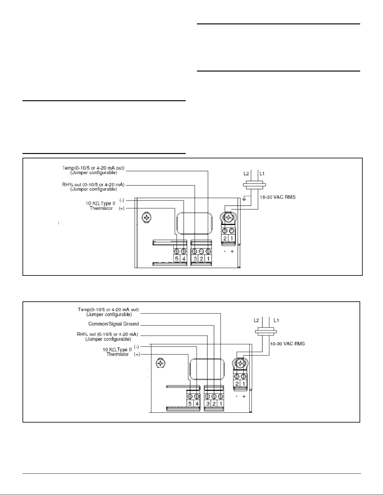
Telaire Humidity/Temperature Wiring Diagrams
The T8700 Telaire Humidity/Temperature family of products has a
configuration that provides active outputs for RH and Temperature
(terminals 1, 2 and 3) as well as a passive connected 10k type II
Thermistor (terminals 4 and 5) and an independent thermistor.
For electrical wiring and power supply requirements, please follow the
specific instructions for wiring. The recommended wire gauge is 18-22
AWG (1.0 to 0.75 metric).
!WARNING!
The T8700 Telaire Humidity/Temperature products have
two terminal pins that are connected inside the sensor to a
common/ground: pin #2on the I/O terminal block and pin
#2 on the power block. Do NOT connect positive (hot) 24
VAC power line to terminal number 2
of the power block.
Caution!
The Telaire Humidity/Temperature products are either 3-wire
or 4-wire type configurations, powered by either AC or DC
voltage. They are not 2-wire or loop-powered devices. Wiring
the units as 2-wire or loop-powered devices will irreparably
damage the sensors and void the warranty.
Note: Fo
r additional flexibility of temperature measurements, the
T8700 models contain a passive thermistor (terminal pins #4
and 5), which is electrically isolated from the other circuitry
and should be wired independently from active RH/temperature
outputs. The thermistor has no connection to the RH
transmitter common ground and/or power.
Figure 1: Wiring for 3-Wire System, AC Power
Figure 2: Wiring for 4-Wire System, AC Power
Page 2 Telaire T8700 Series
 Loading...