

Page 1
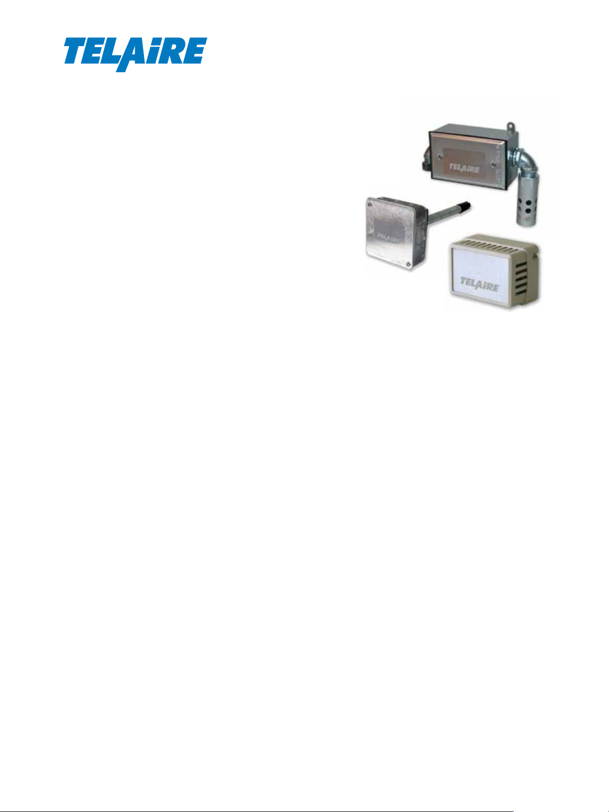
RH/RHT Series
Amphenol
®
Relative Humidity and
Temperature Transmitters
The Relative Humidity (RH) and Temperature
transmitters are designed for continuous
monitoring of relative humidity (RH) or relative
humidity and temperature (RHT). They provide
accurate and reliable measurement for building
automation and environmental control systems.
The units feature very low profile sensor
enclosures that are virtually unnoticeable in most
installations.
The RH and RHT transmitters are available
with ±2%, ±3%, and ±5% RH accuracy (20%
to 95% RH). For monitoring and controlling in
critical environments, the units can be precision
calibrated to 1% accuracy within a specified RH
range.
The RH and RHT transmitters provide a linear
output of 4-20 mA corresponding to 0 to 100%RH.
The RHT transmitter also provides a 4-20 mA
signal corresponding to any of the selected
standard temperature ranges specified.
Features
• Space, Duct, and Outside Air Configurations
• Durable Industrial Enclosures
• Low Profile
• Compact
• Replaceable, Plug-in Bulk Polymer Resistance
RH Sensor
• Resistant to Contamination
• Temperature Compensation
Advanced Sensors
Page 2
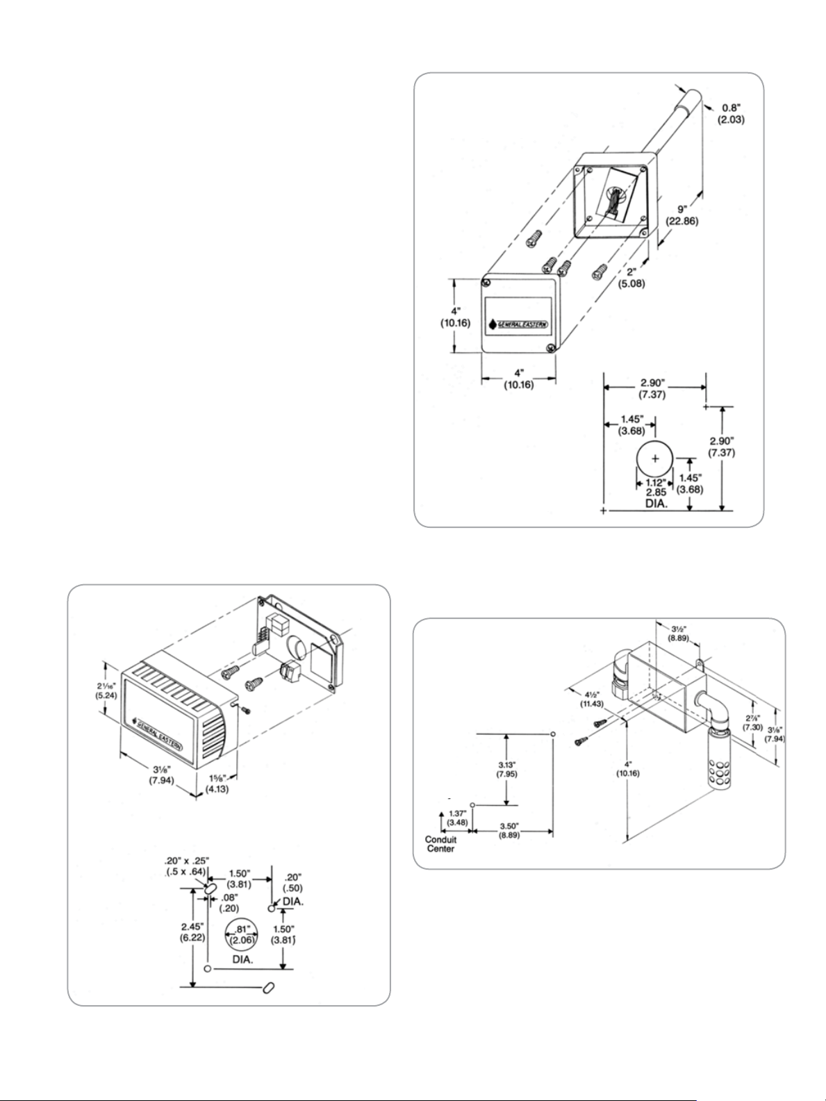
Sensor Enclosure
The relative humidity and temperature sensors are
housed in heavy duty, compact, locking enclosures.
Enclosures may be removed and painted, which further
helps blend them into any environment.
Sensor
The RH sensor incorporates a bulk polymer resistive
element. The polymer is impervious to most
contaminants and, since it is a bulk resistance device,
surface contamination such as dust will not alter the
accuracy of the readings. Imbedded in the polymer is
an interdigitated grid which senses resistance change
as the polymer absorbs or emits molecules of water.
Transmitter
The electronics are contained in a rugged pressurecast aluminum weatherproof housing designed
for maximum protection. Continuous temperature
compensation adjusts for temperature-induced change
in the RH sensor output. The compensation provides
high measurement accuracy over the entire operating
range of the instrument.
Mounting Template
Dimensions and Mounting
RH and RHT Duct Mount
Mounting Template
(Side View)
RH and RHT Outside Air Mount
Mounting Template
RH Space Mount
2
Page 3
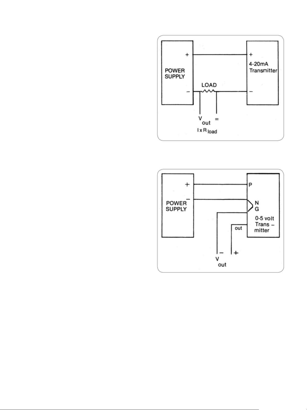
Wiring Guidelines
Outputs: Relative Humidity
4·20 mA Current Output
The 4-20 mA transmitters will provide a linear
proportional signal with 4 mA corresponding to 0%
RH and 20 mA to 100% RH. These are loop powered
devices; therefore, only two wires are required.
0-5 Volt Voltage Output
The 0 to 5 volt transmitters provide a linear
proportional output at terminal “O” with 0 volts
equivalent to 0% RH and 5 volts to 100% RH.
The voltage output transmitters can be wired as a
three wire transmitter or as a four wire transmitter to
eliminate the effects of wire length. The output voltage
is with respect to Terminals “N” (power supply return)
and/or “G” (signal ground) which are common at the
transmitter.
Wiring Diagram Current Unit
Output: Temperature (Optional)
The temperature option (if ordered) is a separate circuit
board but mounted in the same housing along with the
relative humidity transmitter.
The 4·20 mA transmitters output is linear and
proportional to the range specified when the
transmitter was ordered. The low range temperature
(4 mA) is marked on the ZERO pot and the high range
temperature (20 mA) is marked on the SPAN pot.
Standard range is - 20° to 140°F (this range is supplied
when no range is specified at time of ordering).
The temperature transmitters are entirely separate
circuits from the RH transmitters. Transmitters are
loop powered devices. Therefore, only two wires are
required. One wire may be common with the RH
transmitter.
Wiring
Wiring for the transmitter should be twisted pair(s)
16·22 AWG approximately 2 turns per inch. In
installations near electric motors or sensitive electronic
equipment, use shielded cable. Wiring should be run
through conduit using the 1/2” EMT compression fitting
supplied on the unit.
Wiring Diagram Voltage Unit
3
Page 4

RH/RHT Specifications
Humidity
Sensing Element
Resistance change of bulk polymer sensor
Performance
Accuracy at 77°F (25°C)
±2% RH, 20-95% RH
±3% RH,, 20-95% RH
±5% RH, 20 -95% RH
including hysteresis, linearity and repeatability
Mechanical: Case Material
Space: ABS Flame Retardant
Duct: Galvanized Steel
Outside Air: Pressure Cast Aluminum and Galvanized
Steel
Mounting Configurations
Space, Duct, Outside Air
Temperature Effect
Less than 0.06% per °F (0.11% per °C)
Sensor Interchangeability
±3% nominal
Operating Range
RH Sensor: 0%-99%, RH, non·condensing.
-40°F to +170°F (-40°C to +76°C)
Electronics: 0%-95% RH, non.condensing.
-40°F to +130°F (-40°C to +54°C)
Max. Air Velocity
10,000 ft/min
Output Range
2·wire. isolated loop, powered 4-20 mA, 0-100% RH
(standard)
Adjustment
Zero: ±20%. non·interactive
Span: ±10%, non·interactive
Long Term Stability: Less than 1 % drift/year typical
Power
Sensitivity
0.1% RH
Repeatability
0.5% RH
Linearity
See Accuracy
Hysteresis
Less than 1%
Supply Voltage
12-36 VDC
Max Load
W = Supply · 10 VDC
0.02 A
Storage Temperature
-85°F to +158°F (-65°C to +70°C)
4
Page 5

RH/RHT Specifications
Temperature
Sensing Element
Platinum RTD, 4 wire measurement
Performance
Accuracy at 77°F (25”C)
±0.5°F (±0.3°C)
Temperature Effect
Less than 0.01% per °F (0.02% per°C)
Sensitivity
0.1% RH
Repeatability:
0.1% RH
Linearity
Better than 0.1 %
Hysteresis
Less than 0.01%
Optional
0°F to +150°F (-18°C to +66°C)
0°F to +100°F (-18”C to +38°C)
+32°F to +132°F (0°C to +55°C)
+50°F to +130°F (+7°C to +54°C)
-40°F to + 140°F (-40”C to +60°C)
Custom range
Adjustment
Zero: ±10%. non·interactive
Span: ±10%. non-interactive
Long Term Stability: Less than 1% drift per year, typical
Humidity affects you and your operations. Our local
representative Is ready to help in your application. Call
to discuss the proper selection of a humidity device
from the world’s largest selection.
Specifications are subject to change without notice.
Sensor Interchangeability
±0.5°F (±0.03°C)
Output Ranges
4·20 mA
- 20°F to + 140°F (-29°C to +60°C)
5
Page 6
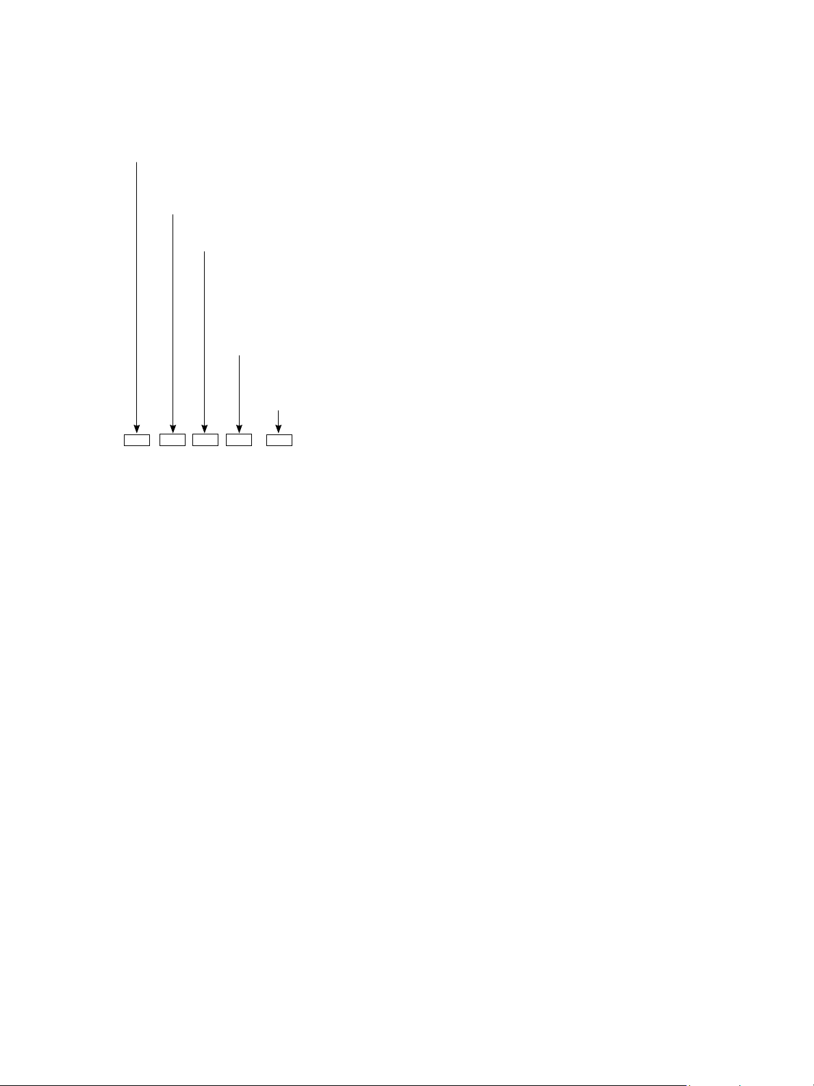
Ordering Information
Amphenol
Model RH
Code
T with Temperature
Code Accuracy
2 2%
3 3%
5 5%
Code Output
I 4 - 20 mA Current
V 0-5 Volltage DC
Code Temperature Channel Range (optional)
1 -20°F to 140°F (Standard)
2 0°F to 150°F
3 0°F to 100°F
4 +32°F to +132°F
5 +50°F to +130°F
6 -40°F to +140°F
7 Custom Range
Code Mounting Configuration
S Space
D Duct
O/A Outside Air
Model RH - - - -
Example 1: To specify an RH transmitter. order: RH-2-I-S.
Exomple 2: To specify an RH transmitter with optional temperature
sensor with standard range (-20°F to + 140°F), order: RHT-2-I-S.
Options
Special calibration to ± 1% accuracy (20% RH span in 20%·- 95% RH range)
www.telaire.com
Advanced Sensors
www.amphenol-sensors.com
© 2014 Amphenol Corporation. All Rights Reserved. Specifications are subject to change without notice.
Other company names and product names used in this document are the registered trademarks or
trademarks of their respective owners.
AAS-920-509A-04/2014
 Loading...