

Telaire T5100-LED Operating Manual
Amphenol
Advanced Sensors
Installing the Sensor
!WARNING!
Before performing service or maintenance operations on
the systems, turn OFF main power switches to the unit.
Electric shock can cause personal injury. Please read and
follow the wiring instructions precisely; miswiring may
cause permanent damage to the product.
Basic Installation
1. Separate the case into its front and rear sections.
2. Secure the rear section of the case to the wall or junction box using
the supplied screws, and make necessary wire connections.
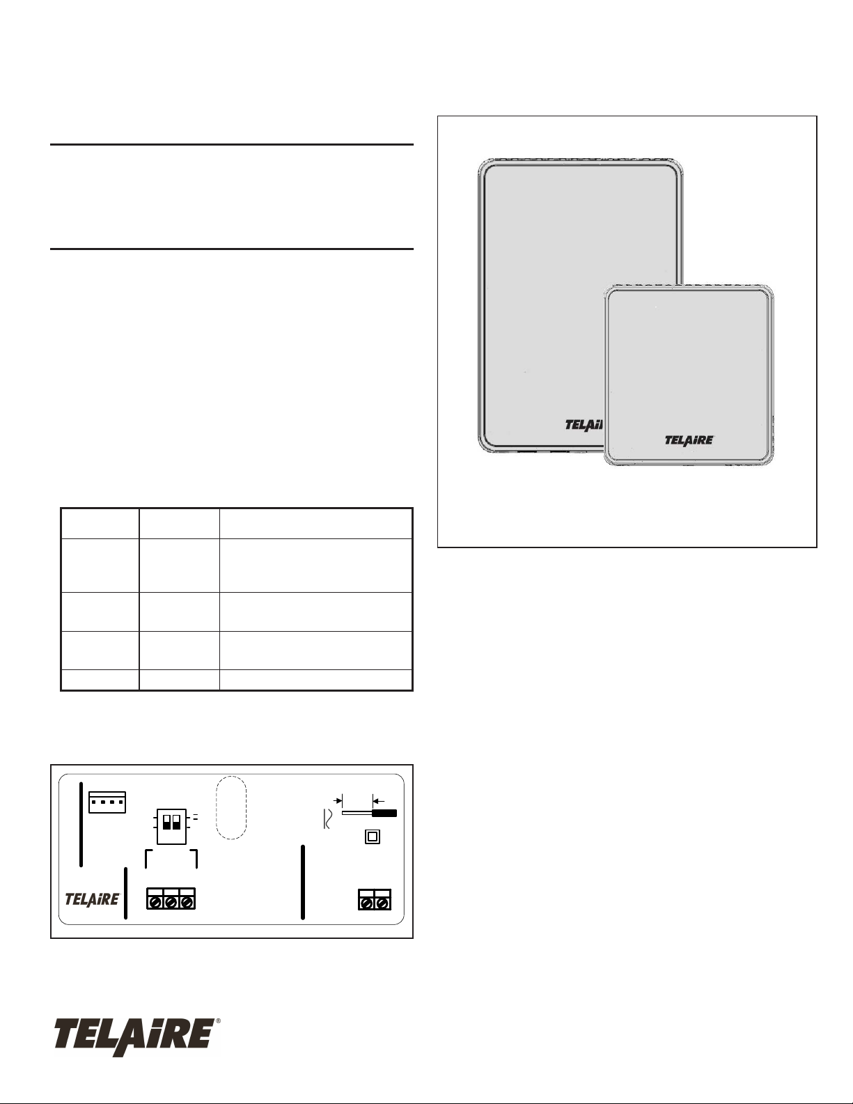
3. Select Voltage or Current output option and Voltage range (0-10 V or
0-5 V) using the SW1 as shown on the internal label (Figure 1) and
Table 1.
Note: SW1 controls both CO
simultaneously.
and Temperature outputs
2
Telaire T5100-LED Series CO2
and Temperature Sensor User
Instructions
Factory default setting is Voltage outputs 0-10V.
Table 1: Voltage and Current Output Options
Switch #1 Switch #2 Configuration
Down, Low Down, Low Factory default setting
CO
0-10 V / 0 - 2000 ppm
2
Temperature 0-10 V/ 0 - 50 °C
Up, High Down, Low CO
Down, Low Up, High CO
Up, High Up, High RESERVED
4. Mount the Controller on the base by aligning the top clips and then
securing to the bottom clips. Secure the Ventostat with the supplied
set screw. A one-minute stabilization warmup will take place.
UIP
J2
SW1
OPTIONS
5V
10V
OUTPUT
1 2
OPTIONS
2
CO
COM
678
I
V
TEMP
OUT
OUT
0-5V/ 0 - 2000 ppm
2
Temperature 0-5 V/ 0 - 50°C
4-20 mA/ 0 - 2000 ppm
2
Temperature 4-20 mA/ 0 - 50°C
STRIP GAUGE
6mm / ¼"
RMS,
AC-/DC-
POWER
18- 42 VDC
MAX RATING 2W PEAK
18- 30 VAC 50/60 Hz
2
1
AC+/DC+
Amphenol Advanced Sensors
6860 Cortona Dr., Suite B
Goleta, CA 93117
www.telaire.com
Figure 1:Internal Label
T63375-003
September 2013
Page 1 of 4
T5100 Wiring Diagrams
!WARNING!
T5100-LED products have two terminal pins that are
connected inside the sensor to a common/ground: pin #7
on the I/O terminal blocks and pin #2 on the power block.
Do NOT connect positive (hot) 24 VAC power line to
terminal number #2 of the terminal block.
Caution!
The T5100-LED products are either 3-wire or 4-wire type
configurations, powered by either AC or DC voltage. They are
not 2-wire or loop-powered devices. Wiring the units as 2-wire
or loop-powered devices will irreparably damage the sensors
and void the warranty.
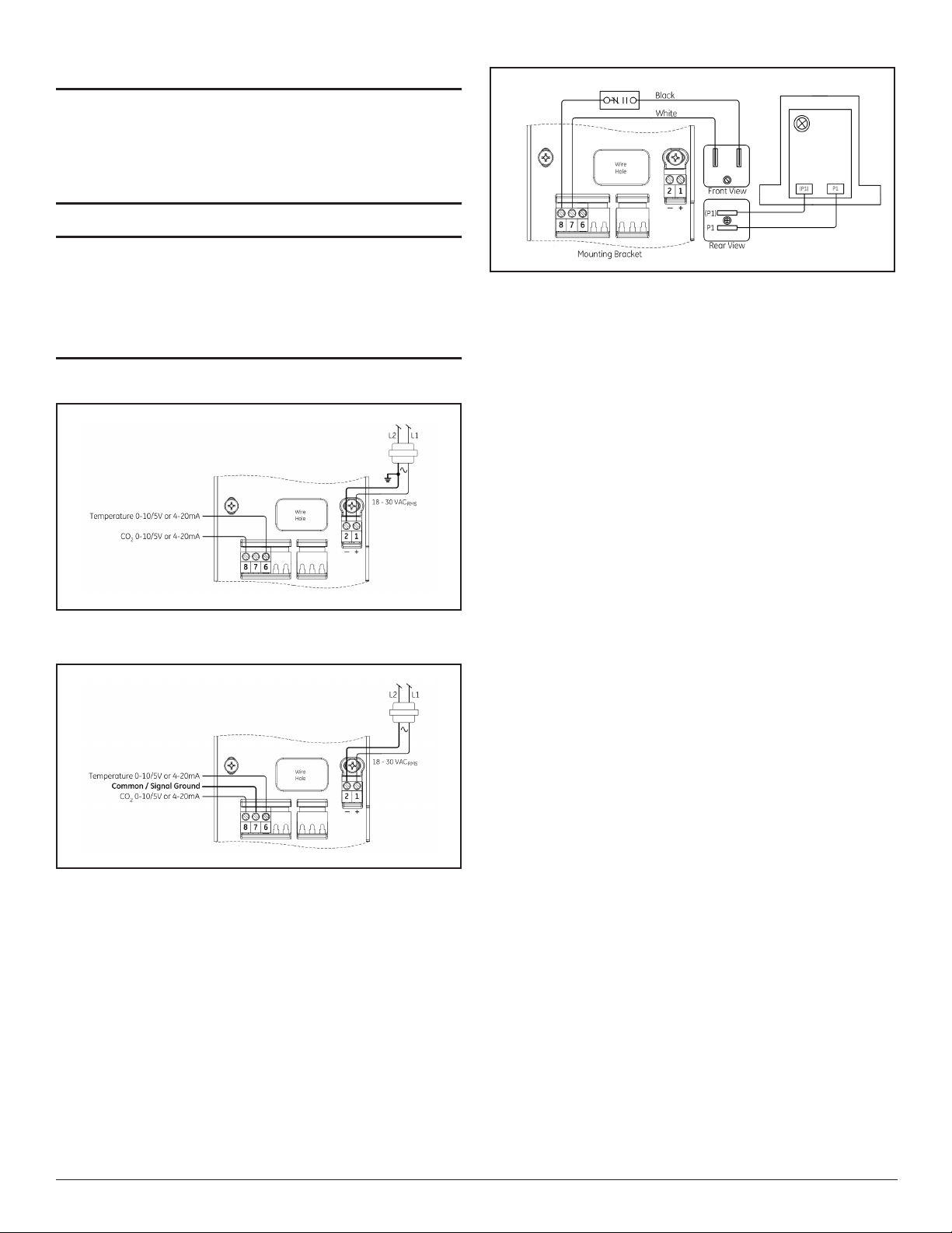
Figure 4: Wiring for CO2 Sensor Voltage Output
LED Display
The T5100-LED has a 5-color LED display that shows the approximate
CO2 concentration. From left to right, the display shows:
• Blue <800 ppm
• Green 800-1200 ppm
• Yellow 1200-1500 ppm
• Red >1500 ppm
Figure 2: Wiring for 3-Wire System - AC Power
Figure 3: Wiring for 4-Wire System - AC Power
• Two red >2000 ppm
Sensing Duct CO2 Concentrations
Duct-Mounting the Enclosures
T5100-LED products can be installed inside the return air ductwork, if
needed. As an alternative, please consider the T8031 unit. When
mounting these products inside the ductwork, seal the hole around the
wires and leave the duct insulation in place to prevent condensation
which may damage the sensor.
Page 2 Telaire T5100-LED Series
 Loading...