

Page 1

Technical Reference
TVS600 & TVS600A Series
Waveform Analyzers Command Reference
070-9917-00
Warning
The servicing instructions are for use by qualified
personnel only. To avoid personal injury, do not
perform any servicing unless you are qualified to
do so. Refer to the Safety Summary prior to
performing service.
This document supports firmware
version 1.5 and above.
Page 2

Copyright T ektronix, Inc. All rights reserved. Licensed software products are owned by Tektronix or its suppliers and
are protected by United States copyright laws and international treaty provisions.
Use, duplication, or disclosure by the Government is subject to restrictions as set forth in subparagraph (c)(1)(ii) of the
Rights in T echnical Data and Computer Software clause at DFARS 252.227-7013, or subparagraphs (c)(1) and (2) of the
Commercial Computer Software – Restricted Rights clause at F AR 52.227-19, as applicable.
T ektronix products are covered by U.S. and foreign patents, issued and pending. Information in this publication supercedes
that in all previously published material. Specifications and price change privileges reserved.
Printed in the U.S.A.
T ektronix, Inc., P.O. Box 1000, Wilsonville, OR 97070–1000
TEKTRONIX and TEK are registered trademarks of T ektronix, Inc.
Page 3

Table of Contents
Command Syntax
Commands
General Safety Summary xv. . . . . . . . . . . . . . . . . . . . . . . . . . . . . . . . . . . .
Related Manuals xvii. . . . . . . . . . . . . . . . . . . . . . . . . . . . . . . . . . . . . . . . . . . . . . . . . .
Command Syntax 1–1. . . . . . . . . . . . . . . . . . . . . . . . . . . . . . . . . . . . . . . . . .
SCPI Commands and Queries 1–1. . . . . . . . . . . . . . . . . . . . . . . . . . . . . . . . . . . . . . .
IEEE 488.2 Common Commands 1–6. . . . . . . . . . . . . . . . . . . . . . . . . . . . . . . . . . . .
Constructed Mnemonics 1–7. . . . . . . . . . . . . . . . . . . . . . . . . . . . . . . . . . . . . . . . . . . .
Commands 2–1. . . . . . . . . . . . . . . . . . . . . . . . . . . . . . . . . . . . . . . . . . . . . . . .
Overview 2–1. . . . . . . . . . . . . . . . . . . . . . . . . . . . . . . . . . . . . . . . . . . . . . . . . . . . . . .
AADVance Subsystem 2–3. . . . . . . . . . . . . . . . . . . . . . . . . . . . . . . . . . . . . . .
AADVance
AADVance? 2–4. . . . . . . . . . . . . . . . . . . . . . . . . . . . . . . . . . . . . . . . . . . . . . . . .
AADVance:COUNt
AADVance:COUNt? 2–5. . . . . . . . . . . . . . . . . . . . . . . . . . . . . . . . . . . . . . . . . . .
AADVance:RECord:COUNt
AADVance:RECord:COUNt? 2–6. . . . . . . . . . . . . . . . . . . . . . . . . . . . . . . . . . . .
AADVance:RECord:STARt
AADVance:RECord:STARt? 2–7. . . . . . . . . . . . . . . . . . . . . . . . . . . . . . . . . . . .
ARM Subsystem 2–9. . . . . . . . . . . . . . . . . . . . . . . . . . . . . . . . . . . . . . . . . . .
ARM:DEFine? (Query Only) 2–10. . . . . . . . . . . . . . . . . . . . . . . . . . . . . . . . . . . . . . . .
ARM:SOURce
ARM:SOURce? 2–11. . . . . . . . . . . . . . . . . . . . . . . . . . . . . . . . . . . . . . . . . . . . . .
AVERage Subsystem 2–13. . . . . . . . . . . . . . . . . . . . . . . . . . . . . . . . . . . . . . . .
AVERage
AVERage? 2–14. . . . . . . . . . . . . . . . . . . . . . . . . . . . . . . . . . . . . . . . . . . . . . . . . . .
AVERage:COUNt
AVERage:COUNt? 2–15. . . . . . . . . . . . . . . . . . . . . . . . . . . . . . . . . . . . . . . . . . . .
AVERage:TYPE
AVERage:TYPE? 2–16. . . . . . . . . . . . . . . . . . . . . . . . . . . . . . . . . . . . . . . . . . . . .
CALCulate Subsystem 2–19. . . . . . . . . . . . . . . . . . . . . . . . . . . . . . . . . . . . . .
CALCulate:AAMList
CALCulate:AAMList? 2–20. . . . . . . . . . . . . . . . . . . . . . . . . . . . . . . . . . . . . . . . .
CALCulate:AAMList:STATe
CALCulate:AAMList:STATe? 2–23. . . . . . . . . . . . . . . . . . . . . . . . . . . . . . . . . . .
CALCulate:DATA? (Query Only) 2–24. . . . . . . . . . . . . . . . . . . . . . . . . . . . . . . . . . . .
CALCulate:DATA:PREamble? (Query Only) 2–25. . . . . . . . . . . . . . . . . . . . . . . . . . .
CALCulate:DERivative:STATe
CALCulate:DERivative:STATe? 2–26. . . . . . . . . . . . . . . . . . . . . . . . . . . . . . . . .
CALCulate:FEED[1]
CALCulate:FEED[1]? 2–27. . . . . . . . . . . . . . . . . . . . . . . . . . . . . . . . . . . . . . . . .
CALCulate:FEED2
CALCulate:FEED2? 2–28. . . . . . . . . . . . . . . . . . . . . . . . . . . . . . . . . . . . . . . . . . .
TVS600 & TVS600A Command Reference
i
Page 4

Table of Contents
CALCulate:FEED2:CONText
CALCulate:FEED2:CONText? 2–30. . . . . . . . . . . . . . . . . . . . . . . . . . . . . . . . . . .
CALCulate:FILTer:FREQuency[:TYPE]
CALCulate:FILTer:FREQuency[:TYPE]? 2–32. . . . . . . . . . . . . . . . . . . . . . . . . .
CALCulate:FILTer:FREQuency:CENTer
CALCulate:FILTer:FREQuency:CENTer? 2–33. . . . . . . . . . . . . . . . . . . . . . . . . .
CALCulate:FILTer:FREQuency:HPASs
CALCulate:FILTer:FREQuency:HPASs? 2–35. . . . . . . . . . . . . . . . . . . . . . . . . . .
CALCulate:FILTer:FREQuency:LPASs
CALCulate:FILTer:FREQuency:LPASs? 2–36. . . . . . . . . . . . . . . . . . . . . . . . . . .
CALCulate:FILTer:FREQuency:SPAN
CALCulate:FILTer:FREQuency:SPAN? 2–37. . . . . . . . . . . . . . . . . . . . . . . . . . .
CALCulate:FILTer:FREQuency:SREJection
CALCulate:FILTer:FREQuency:SREJection? 2–38. . . . . . . . . . . . . . . . . . . . . . .
CALCulate:FILTer:FREQuency:STARt
CALCulate:FILTer:FREQuency:STARt? 2–39. . . . . . . . . . . . . . . . . . . . . . . . . . .
CALCulate:FILTer:FREQuency:STATe
CALCulate:FILTer:FREQuency:STATe? 2–41. . . . . . . . . . . . . . . . . . . . . . . . . . .
CALCulate:FILTer:FREQuency:STOP
CALCulate:FILTer:FREQuency:STOP? 2–42. . . . . . . . . . . . . . . . . . . . . . . . . . .
CALCulate:FILTer:FREQuency:TWIDth
CALCulate:FILTer:FREQuency:TWIDth? 2–43. . . . . . . . . . . . . . . . . . . . . . . . . .
CALCulate:FORMat
CALCulate:FORMat? 2–44. . . . . . . . . . . . . . . . . . . . . . . . . . . . . . . . . . . . . . . . . .
CALCulate:IMMediate
CALCulate:IMMediate? 2–46. . . . . . . . . . . . . . . . . . . . . . . . . . . . . . . . . . . . . . . .
CALCulate:INTegral:STATe
CALCulate:INTegral:STATe? 2–47. . . . . . . . . . . . . . . . . . . . . . . . . . . . . . . . . . . .
CALCulate:PATH
CALCulate:PATH? 2–48. . . . . . . . . . . . . . . . . . . . . . . . . . . . . . . . . . . . . . . . . . . .
CALCulate:PATH:EXPRession
CALCulate:PATH:EXPRession? 2–49. . . . . . . . . . . . . . . . . . . . . . . . . . . . . . . . .
CALCulate:SMOothing
CALCulate:SMOothing? 2–51. . . . . . . . . . . . . . . . . . . . . . . . . . . . . . . . . . . . . . .
CALCulate:SMOothing:POINts
CALCulate:SMOothing:POINts? 2–52. . . . . . . . . . . . . . . . . . . . . . . . . . . . . . . . .
CALCulate:TRANsform:FREQuency:STATe
CALCulate:TRANsform:FREQuency:STATe? 2–53. . . . . . . . . . . . . . . . . . . . . .
CALCulate:TRANsform:FREQuency:WINDow
CALCulate:TRANsform:FREQuency:WINDow? 2–54. . . . . . . . . . . . . . . . . . . .
CALCulate:WMList
CALCulate:WMList? 2–56. . . . . . . . . . . . . . . . . . . . . . . . . . . . . . . . . . . . . . . . . .
CALCulate:WMList:STATe
CALCulate:WMList:STATe? 2–61. . . . . . . . . . . . . . . . . . . . . . . . . . . . . . . . . . . .
CALCulate:WMParameter:EDGE
CALCulate:WMParameter:EDGE? 2–62. . . . . . . . . . . . . . . . . . . . . . . . . . . . . . .
CALCulate:WMParameter:GATE
CALCulate:WMParameter:GATE?
TVS600A Models Only 2–63. . . . . . . . . . . . . . . . . . . . . . . . . . . . . . . . . . . . . . . .
CALCulate:WMParameter:GATE:METHod
CALCulate:WMParameter:GATE:METHod?
TVS600A Models Only 2–64. . . . . . . . . . . . . . . . . . . . . . . . . . . . . . . . . . . . . . . .
ii
TVS600 & TVS600A Command Reference
Page 5

Table of Contents
CALCulate:WMParameter:GATE:STARt:ABSolute
CALCulate:WMParameter:GATE:STARt:ABSolute?
TVS600A Models Only 2–65. . . . . . . . . . . . . . . . . . . . . . . . . . . . . . . . . . . . . . . .
CALCulate:WMParameter:GATE:STARt:RELative
CALCulate:WMParameter:GATE:STARt:RELative?
TVS600A Models Only 2–66. . . . . . . . . . . . . . . . . . . . . . . . . . . . . . . . . . . . . . . .
CALCulate:WMParameter:GATE:STOP:ABSolute
CALCulate:WMParameter:GATE:STOP:ABSolute?
TVS600A Models Only 2–67. . . . . . . . . . . . . . . . . . . . . . . . . . . . . . . . . . . . . . . .
CALCulate:WMParameter:GATE:STOP:RELative
CALCulate:WMParameter:GATE:STOP:RELative?
TVS600A Models Only 2–68. . . . . . . . . . . . . . . . . . . . . . . . . . . . . . . . . . . . . . . .
CALCulate:WMParameter:HIGH
CALCulate:WMParameter:HIGH? 2–69. . . . . . . . . . . . . . . . . . . . . . . . . . . . . . . .
CALCulate:WMParameter:HMEThod
CALCulate:WMParameter:HMEThod? 2–70. . . . . . . . . . . . . . . . . . . . . . . . . . . .
CALCulate:WMParameter:LOW
CALCulate:WMParameter:LOW? 2–71. . . . . . . . . . . . . . . . . . . . . . . . . . . . . . . .
CALCulate:WMParameter:LMEThod
CALCulate:WMParameter:LMEThod? 2–72. . . . . . . . . . . . . . . . . . . . . . . . . . . .
CALCulate:WMParameter:HREFerence
CALCulate:WMParameter:HREFerence? 2–74. . . . . . . . . . . . . . . . . . . . . . . . . .
CALCulate:WMParameter:HREFerence:RELative
CALCulate:WMParameter:HREFerence:RELative? 2–75. . . . . . . . . . . . . . . . . .
CALCulate:WMParameter:LREFerence
CALCulate:WMParameter:LREFerence? 2–76. . . . . . . . . . . . . . . . . . . . . . . . . .
CALCulate:WMParameter:LREFerence:RELative
CALCulate:WMParameter:LREFerence:RELative? 2–77. . . . . . . . . . . . . . . . . .
CALCulate:WMParameter:MREFerence
CALCulate:WMParameter:MREFerence? 2–78. . . . . . . . . . . . . . . . . . . . . . . . . .
CALCulate:WMParameter:MREFerence:HYSTeresis
CALCulate:WMParameter:MREFerence:HYSTeresis? 2–79. . . . . . . . . . . . . . . .
CALCulate:WMParameter:MREFerence:RELative
CALCulate:WMParameter:MREFerence:RELative? 2–80. . . . . . . . . . . . . . . . . .
CALCulate:WMParameter:RMEThod
CALCulate:WMParameter:RMEThod? 2–82. . . . . . . . . . . . . . . . . . . . . . . . . . . .
CALCulate:WMParameter:SLOPe
CALCulate:WMParameter:SLOPe? 2–83. . . . . . . . . . . . . . . . . . . . . . . . . . . . . . .
CALibration Subsystem 2–85. . . . . . . . . . . . . . . . . . . . . . . . . . . . . . . . . . . . .
CALibration
CALibration? 2–86. . . . . . . . . . . . . . . . . . . . . . . . . . . . . . . . . . . . . . . . . . . . . . . .
CALibration:PROBe
CALibration:PROBe?
TVS600A Models Only 2–87. . . . . . . . . . . . . . . . . . . . . . . . . . . . . . . . . . . . . . . .
CALibration:PROBe:RESults?
TVS600A Models Only 2–89. . . . . . . . . . . . . . . . . . . . . . . . . . . . . . . . . . . . . . . .
CALibration:RESults? (Query Only) 2–90. . . . . . . . . . . . . . . . . . . . . . . . . . . . . . . . . .
CALibration:RESults:VERBose? (Query Only) 2–91. . . . . . . . . . . . . . . . . . . . . . . . .
FORMat Subsystem 2–93. . . . . . . . . . . . . . . . . . . . . . . . . . . . . . . . . . . . . . . .
FORMat
FORMat? 2–94. . . . . . . . . . . . . . . . . . . . . . . . . . . . . . . . . . . . . . . . . . . . . . . . . . . .
FORMat:BORDer
FORMat:BORDer? 2–95. . . . . . . . . . . . . . . . . . . . . . . . . . . . . . . . . . . . . . . . . . . .
TVS600 & TVS600A Command Reference
iii
Page 6

Table of Contents
FORMat:CALCulate
FORMat:CALCulate? 2–96. . . . . . . . . . . . . . . . . . . . . . . . . . . . . . . . . . . . . . . . . .
FORMat:DINTerchange
FORMat:DINTerchange?
TVS600A Models Only 2–97. . . . . . . . . . . . . . . . . . . . . . . . . . . . . . . . . . . . . . . .
FORMat:TRACe:AATS
FORMat:TRACe:AATS? 2–98. . . . . . . . . . . . . . . . . . . . . . . . . . . . . . . . . . . . . . .
FORMat:TRACe:REF
FORMat:TRACe:REF?
TVS600A Models Only 2–99. . . . . . . . . . . . . . . . . . . . . . . . . . . . . . . . . . . . . . . .
FUNCtion and DATA Subsystems 2–101. . . . . . . . . . . . . . . . . . . . . . . . . . . . .
FUNCtion[:ON]
FUNCtion[:ON]? 2–102. . . . . . . . . . . . . . . . . . . . . . . . . . . . . . . . . . . . . . . . . . . . .
FUNCtion[:ON]:ALL 2–103. . . . . . . . . . . . . . . . . . . . . . . . . . . . . . . . . . . . . . . . . . . . .
FUNCtion[:ON]:COUNt? (Query Only) 2–104. . . . . . . . . . . . . . . . . . . . . . . . . . . . . . .
FUNCtion:OFF
FUNCtion:OFF? 2–105. . . . . . . . . . . . . . . . . . . . . . . . . . . . . . . . . . . . . . . . . . . . . .
FUNCtion:OFF:ALL 2–106. . . . . . . . . . . . . . . . . . . . . . . . . . . . . . . . . . . . . . . . . . . . . .
FUNCtion:OFF:COUNt? (Query Only) 2–107. . . . . . . . . . . . . . . . . . . . . . . . . . . . . . .
FUNCtion:CONCurrent
FUNCtion:CONCurrent? 2–108. . . . . . . . . . . . . . . . . . . . . . . . . . . . . . . . . . . . . . .
FUNCtion:STATe
FUNCtion:STATe? 2–109. . . . . . . . . . . . . . . . . . . . . . . . . . . . . . . . . . . . . . . . . . . .
DATA? (Query Only) 2–110. . . . . . . . . . . . . . . . . . . . . . . . . . . . . . . . . . . . . . . . . . . . . .
DATA:LIST
DATA:LIST? 2–111. . . . . . . . . . . . . . . . . . . . . . . . . . . . . . . . . . . . . . . . . . . . . . . . .
DATA:PREamble? (Query Only) 2–112. . . . . . . . . . . . . . . . . . . . . . . . . . . . . . . . . . . . .
INITiate and ABORt Subsystems 2–115. . . . . . . . . . . . . . . . . . . . . . . . . . . . .
INITiate 2–116. . . . . . . . . . . . . . . . . . . . . . . . . . . . . . . . . . . . . . . . . . . . . . . . . . . . . . . .
INITiate:CONTinuous
INITiate:CONTinuous? 2–116. . . . . . . . . . . . . . . . . . . . . . . . . . . . . . . . . . . . . . . . .
INITiate:COUNt
INITiate:COUNt? 2–118. . . . . . . . . . . . . . . . . . . . . . . . . . . . . . . . . . . . . . . . . . . . .
ABORt 2–119. . . . . . . . . . . . . . . . . . . . . . . . . . . . . . . . . . . . . . . . . . . . . . . . . . . . . . . . .
INPut Subsystem 2–121. . . . . . . . . . . . . . . . . . . . . . . . . . . . . . . . . . . . . . . . . . .
INPut:COUPling
INPut:COUPling? 2–122. . . . . . . . . . . . . . . . . . . . . . . . . . . . . . . . . . . . . . . . . . . . .
INPut:FILTer
INPut:FILTer? 2–123. . . . . . . . . . . . . . . . . . . . . . . . . . . . . . . . . . . . . . . . . . . . . . . .
INPut:FILTer:FREQuency
INPut:FILTer:FREQuency? 2–124. . . . . . . . . . . . . . . . . . . . . . . . . . . . . . . . . . . . .
INPut:IMPedance
INPut:IMPedance? 2–125. . . . . . . . . . . . . . . . . . . . . . . . . . . . . . . . . . . . . . . . . . . .
INPut:PROBe:ATTenuation? 2–126. . . . . . . . . . . . . . . . . . . . . . . . . . . . . . . . . . . . . . . .
INPut:PROBe:IDENtification?
TVS600A Models Only 2–127. . . . . . . . . . . . . . . . . . . . . . . . . . . . . . . . . . . . . . . .
INPut:PROBe:OFFSet?
TVS600A Models Only 2–128. . . . . . . . . . . . . . . . . . . . . . . . . . . . . . . . . . . . . . . .
INPut:PROTection:STATe
INPut:PROTection:STATe? 2–129. . . . . . . . . . . . . . . . . . . . . . . . . . . . . . . . . . . . .
MEMory Subsystem 2–131. . . . . . . . . . . . . . . . . . . . . . . . . . . . . . . . . . . . . . . .
iv
TVS600 & TVS600A Command Reference
Page 7

Table of Contents
MEMory:DATA
MEMory:DATA? 2–132. . . . . . . . . . . . . . . . . . . . . . . . . . . . . . . . . . . . . . . . . . . . .
MEMory:NSTates? (Query Only) 2–134. . . . . . . . . . . . . . . . . . . . . . . . . . . . . . . . . . . .
MEMory:STATe:CATalog? (Query Only) 2–135. . . . . . . . . . . . . . . . . . . . . . . . . . . . . .
MEMory:STATe:DEFine? (Query Only) 2–136. . . . . . . . . . . . . . . . . . . . . . . . . . . . . . .
OUTPut Subsystem 2–137. . . . . . . . . . . . . . . . . . . . . . . . . . . . . . . . . . . . . . . . .
OUTPut:ECLTrg<n>
OUTPut:ECLTrg<n>? 2–138. . . . . . . . . . . . . . . . . . . . . . . . . . . . . . . . . . . . . . . . . .
OUTPut:ECLTrg<n>:POLarity
OUTPut:ECLTrg<n>:POLarity? 2–139. . . . . . . . . . . . . . . . . . . . . . . . . . . . . . . . . .
OUTPut:ECLTrg<n>:SOURce
OUTPut:ECLTrg<n>:SOURce? 2–140. . . . . . . . . . . . . . . . . . . . . . . . . . . . . . . . . .
OUTPut:PCOMpensate
OUTPut:PCOMpensate? 2–141. . . . . . . . . . . . . . . . . . . . . . . . . . . . . . . . . . . . . . . .
OUTPut:PCOMpensate:FUNCtion
OUTPut:PCOMpensate:FUNCtion? 2–142. . . . . . . . . . . . . . . . . . . . . . . . . . . . . . .
OUTPut:REFerence
OUTPut:REFerence? 2–143. . . . . . . . . . . . . . . . . . . . . . . . . . . . . . . . . . . . . . . . . .
OUTPut:REFerence:FUNCtion
OUTPut:REFerence:FUNCtion? 2–144. . . . . . . . . . . . . . . . . . . . . . . . . . . . . . . . .
OUTPut:TTLTrg<n>
OUTPut:TTLTrg<n>? 2–145. . . . . . . . . . . . . . . . . . . . . . . . . . . . . . . . . . . . . . . . . .
OUTPut:TTLTrg<n>:POLarity
OUTPut:TTLTrg<n>:POLarity? 2–146. . . . . . . . . . . . . . . . . . . . . . . . . . . . . . . . . .
OUTPut:TTLTrg<n>:SOURce
OUTPut:TTLTrg<n>:SOURce? 2–147. . . . . . . . . . . . . . . . . . . . . . . . . . . . . . . . . .
ROSCillator Subsystem 2–149. . . . . . . . . . . . . . . . . . . . . . . . . . . . . . . . . . . . .
ROSCillator:SOURce
ROSCillator:SOURce? 2–150. . . . . . . . . . . . . . . . . . . . . . . . . . . . . . . . . . . . . . . . .
STATus Subsystem 2–151. . . . . . . . . . . . . . . . . . . . . . . . . . . . . . . . . . . . . . . . . .
STATus:OPERation? (Query Only) 2–152. . . . . . . . . . . . . . . . . . . . . . . . . . . . . . . . . . .
ST ATus:OPERation:CONDition? (Query Only) 2–154. . . . . . . . . . . . . . . . . . . . . . . . .
STATus:OPERation:ENABle
STATus:OPERation:ENABle? 2–155. . . . . . . . . . . . . . . . . . . . . . . . . . . . . . . . . . .
STATus:OPERation:NTRansition
STATus:OPERation:NTRansition? 2–156. . . . . . . . . . . . . . . . . . . . . . . . . . . . . . . .
STATus:OPERation:PTRansition
STATus:OPERation:PTRansition? 2–157. . . . . . . . . . . . . . . . . . . . . . . . . . . . . . . .
STATus:OPERation:QENable:NTRansition
STATus:OPERation:QENable:NTRansition? 2–158. . . . . . . . . . . . . . . . . . . . . . . .
STATus:OPERation:QENable:PTRansition
STATus:OPERation:QENable:PTRansition? 2–159. . . . . . . . . . . . . . . . . . . . . . . .
STATus:PRESet 2–161. . . . . . . . . . . . . . . . . . . . . . . . . . . . . . . . . . . . . . . . . . . . . . . . . .
ST ATus:QUEStionable? (Query Only) 2–161. . . . . . . . . . . . . . . . . . . . . . . . . . . . . . . .
ST ATus:QUEStionable:CONDition? (Query Only) 2–163. . . . . . . . . . . . . . . . . . . . . .
STATus:QUEStionable:ENABle
STATus:QUEStionable:ENABle? 2–164. . . . . . . . . . . . . . . . . . . . . . . . . . . . . . . . .
STATus:QUEStionable:NTRansition
STATus:QUEStionable:NTRansition? 2–165. . . . . . . . . . . . . . . . . . . . . . . . . . . . .
STATus:QUEStionable:PTRansition
STATus:QUEStionable:PTRansition? 2–166. . . . . . . . . . . . . . . . . . . . . . . . . . . . .
STATus:QUEStionable:QENable:NTRansition
STATus:QUEStionable:QENable:NTRansition? 2–167. . . . . . . . . . . . . . . . . . . . .
TVS600 & TVS600A Command Reference
v
Page 8

Table of Contents
STATus:QUEStionable:QENable:PTRansition
STATus:QUEStionable:QENable:PTRansition? 2–168. . . . . . . . . . . . . . . . . . . . .
STATus:SESR:QENable
STATus:SESR:QENable? 2–170. . . . . . . . . . . . . . . . . . . . . . . . . . . . . . . . . . . . . . .
SWEep Subsystem 2–171. . . . . . . . . . . . . . . . . . . . . . . . . . . . . . . . . . . . . . . . . .
SWEep:OFFSet:POINts
SWEep:OFFSet:POINts? 2–172. . . . . . . . . . . . . . . . . . . . . . . . . . . . . . . . . . . . . . .
SWEep:OFFSet:TIME
SWEep:OFFSet:TIME? 2–173. . . . . . . . . . . . . . . . . . . . . . . . . . . . . . . . . . . . . . . .
SWEep:OREFerence:LOCation
SWEep:OREFerence:LOCation? 2–175. . . . . . . . . . . . . . . . . . . . . . . . . . . . . . . . .
SWEep:POINts
SWEep:POINts? 2–176. . . . . . . . . . . . . . . . . . . . . . . . . . . . . . . . . . . . . . . . . . . . . .
SWEep:TIME
SWEep:TIME? 2–178. . . . . . . . . . . . . . . . . . . . . . . . . . . . . . . . . . . . . . . . . . . . . . .
SWEep:TINTerval
SWEep:TINTerval? 2–180. . . . . . . . . . . . . . . . . . . . . . . . . . . . . . . . . . . . . . . . . . . .
SYSTem Subsystem 2–183. . . . . . . . . . . . . . . . . . . . . . . . . . . . . . . . . . . . . . . . .
SYSTem:AUToset:SWEep
TVS600A Models Only 2–184. . . . . . . . . . . . . . . . . . . . . . . . . . . . . . . . . . . . . . . .
SYSTem:AUToset:TRIGger
TVS600A Models Only 2–185. . . . . . . . . . . . . . . . . . . . . . . . . . . . . . . . . . . . . . . .
SYSTem:AUToset:VOLTage
TVS600A Models Only 2–186. . . . . . . . . . . . . . . . . . . . . . . . . . . . . . . . . . . . . . . .
SYSTem:BDATe?
SYSTem:BDATe
TVS600A Models Only 2–188. . . . . . . . . . . . . . . . . . . . . . . . . . . . . . . . . . . . . . . .
SYSTem:CDATe?
SYSTem:CDATe
TVS600A Models Only 2–189. . . . . . . . . . . . . . . . . . . . . . . . . . . . . . . . . . . . . . . .
SYSTem:COMMunicate:SERial:BAUD
SYSTem:COMMunicate:SERial:BAUD? 2–190. . . . . . . . . . . . . . . . . . . . . . . . . .
SYSTem:COMMunicate:SERial:CONTrol:DCD
SYSTem:COMMunicate:SERial:CONTrol:DCD? 2–191. . . . . . . . . . . . . . . . . . . .
SYSTem:COMMunicate:SERial:CONTrol:RTS
SYSTem:COMMunicate:SERial:CONTrol:RTS? 2–192. . . . . . . . . . . . . . . . . . . .
SYSTem:COMMunicate:SERial:ECHO
SYSTem:COMMunicate:SERial:ECHO? 2–193. . . . . . . . . . . . . . . . . . . . . . . . . . .
SYSTem:COMMunicate:SERial:ERESponse
SYSTem:COMMunicate:SERial:ERESponse? 2–193. . . . . . . . . . . . . . . . . . . . . .
SYSTem:COMMunicate:SERial:LBUFfer
SYSTem:COMMunicate:SERial:LBUFfer? 2–194. . . . . . . . . . . . . . . . . . . . . . . . .
SYSTem:COMMunicate:SERial:PACE
SYSTem:COMMunicate:SERial:PACE? 2–196. . . . . . . . . . . . . . . . . . . . . . . . . . .
SYSTem:COMMunicate:SERial:PARity
SYSTem:COMMunicate:SERial:PARity? 2–197. . . . . . . . . . . . . . . . . . . . . . . . . .
SYSTem:COMMunicate:SERial:PRESet 2–197. . . . . . . . . . . . . . . . . . . . . . . . . . . . . .
SYSTem:COMMunicate:SERial:SBITs
SYSTem:COMMunicate:SERial:SBITs? 2–199. . . . . . . . . . . . . . . . . . . . . . . . . . .
SYST em:ERRor? (Query Only) 2–200. . . . . . . . . . . . . . . . . . . . . . . . . . . . . . . . . . . . . .
SYST em:ERRor:ALL? (Query Only) 2–201. . . . . . . . . . . . . . . . . . . . . . . . . . . . . . . . .
SYST em:ERRor:CODE? (Query Only) 2–202. . . . . . . . . . . . . . . . . . . . . . . . . . . . . . . .
SYST em:ERRor:CODE:ALL? (Query Only) 2–203. . . . . . . . . . . . . . . . . . . . . . . . . . .
vi
TVS600 & TVS600A Command Reference
Page 9

Table of Contents
SYST em:ERRor:COUNt? (Query Only) 2–204. . . . . . . . . . . . . . . . . . . . . . . . . . . . . . .
SYSTem:PROTect
SYSTem:PROTect? 2–204. . . . . . . . . . . . . . . . . . . . . . . . . . . . . . . . . . . . . . . . . . . .
SYSTem:SECurity:IMMediate 2–205. . . . . . . . . . . . . . . . . . . . . . . . . . . . . . . . . . . . . .
SYSTem:SET
SYSTem:SET? 2–206. . . . . . . . . . . . . . . . . . . . . . . . . . . . . . . . . . . . . . . . . . . . . . .
SYST em:VERSion? (Query Only) 2–207. . . . . . . . . . . . . . . . . . . . . . . . . . . . . . . . . . .
TEST Subsystem 2–209. . . . . . . . . . . . . . . . . . . . . . . . . . . . . . . . . . . . . . . . . . .
TEST
TEST? 2–210. . . . . . . . . . . . . . . . . . . . . . . . . . . . . . . . . . . . . . . . . . . . . . . . . . . . . .
TEST:RESults? (Query Only) 2–211. . . . . . . . . . . . . . . . . . . . . . . . . . . . . . . . . . . . . . .
TEST:RESults:VERBose? (Query Only) 2–212. . . . . . . . . . . . . . . . . . . . . . . . . . . . . . .
TEST:STOP
TVS600A Models Only 2–213. . . . . . . . . . . . . . . . . . . . . . . . . . . . . . . . . . . . . . . .
TRACe Subsystem 2–215. . . . . . . . . . . . . . . . . . . . . . . . . . . . . . . . . . . . . . . . . .
TRACe
TRACe? 2–216. . . . . . . . . . . . . . . . . . . . . . . . . . . . . . . . . . . . . . . . . . . . . . . . . . . .
Query 2–216. . . . . . . . . . . . . . . . . . . . . . . . . . . . . . . . . . . . . . . . . . . . . . . . . . . . . . .
TRACe:CATalog? 2–219. . . . . . . . . . . . . . . . . . . . . . . . . . . . . . . . . . . . . . . . . . . . . . . .
TRACe:COPY 2–220. . . . . . . . . . . . . . . . . . . . . . . . . . . . . . . . . . . . . . . . . . . . . . . . . . .
TRACe:DELete
TVS600A Models Only 2–221. . . . . . . . . . . . . . . . . . . . . . . . . . . . . . . . . . . . . . . .
TRACe:DELete:ALL
TVS600A Models Only 2–222. . . . . . . . . . . . . . . . . . . . . . . . . . . . . . . . . . . . . . . .
TRACe:FEED? 2–223. . . . . . . . . . . . . . . . . . . . . . . . . . . . . . . . . . . . . . . . . . . . . . . . . .
TRACe:LIST
TRACe:LIST? 2–224. . . . . . . . . . . . . . . . . . . . . . . . . . . . . . . . . . . . . . . . . . . . . . . .
TRACe:POINts? 2–225. . . . . . . . . . . . . . . . . . . . . . . . . . . . . . . . . . . . . . . . . . . . . . . . .
TRACe:PREamble? 2–227. . . . . . . . . . . . . . . . . . . . . . . . . . . . . . . . . . . . . . . . . . . . . . .
TRIGger[:A] Subsystem 2–229. . . . . . . . . . . . . . . . . . . . . . . . . . . . . . . . . . . . .
TRIGger:ATRigger
TRIGger:ATRigger? 2–230. . . . . . . . . . . . . . . . . . . . . . . . . . . . . . . . . . . . . . . . . . .
TRIGger:COUPling
TRIGger:COUPling? 2–231. . . . . . . . . . . . . . . . . . . . . . . . . . . . . . . . . . . . . . . . . .
TRIGger:COUPling:<preset> 2–232. . . . . . . . . . . . . . . . . . . . . . . . . . . . . . . . . . . . . . .
TRIGger:DEFine? (Query Only) 2–233. . . . . . . . . . . . . . . . . . . . . . . . . . . . . . . . . . . . .
TRIGger:DELay
TRIGger:DELay? 2–234. . . . . . . . . . . . . . . . . . . . . . . . . . . . . . . . . . . . . . . . . . . . .
TRIGger:FILTer[:LPASs]
TRIGger:FILTer[:LPASs]? 2–235. . . . . . . . . . . . . . . . . . . . . . . . . . . . . . . . . . . . . .
TRIGger:FILTer:HPASs
TRIGger:FILTer:HPASs? 2–236. . . . . . . . . . . . . . . . . . . . . . . . . . . . . . . . . . . . . . .
TRIGger:FILTer:NREJect
TRIGger:FILTer:NREJect? 2–237. . . . . . . . . . . . . . . . . . . . . . . . . . . . . . . . . . . . . .
TRIGger:HOLDoff:TIME
TRIGger:HOLDoff:TIME? 2–238. . . . . . . . . . . . . . . . . . . . . . . . . . . . . . . . . . . . . .
TRIGger:LEVel
TRIGger:LEVel? 2–239. . . . . . . . . . . . . . . . . . . . . . . . . . . . . . . . . . . . . . . . . . . . . .
TRIGger:METastable:STATe
TRIGger:METastable:STATe?
TVS600A Models Only 2–240. . . . . . . . . . . . . . . . . . . . . . . . . . . . . . . . . . . . . . . .
TRIGger:SLOPe
TRIGger:SLOPe? 2–241. . . . . . . . . . . . . . . . . . . . . . . . . . . . . . . . . . . . . . . . . . . . .
TVS600 & TVS600A Command Reference
vii
Page 10

Table of Contents
TRIGger:SOURce
TRIGger:SOURce? 2–242. . . . . . . . . . . . . . . . . . . . . . . . . . . . . . . . . . . . . . . . . . . .
TRIGger:TYPE
TRIGger:TYPE? 2–243. . . . . . . . . . . . . . . . . . . . . . . . . . . . . . . . . . . . . . . . . . . . . .
TRIGger:B Subsystem 2–245. . . . . . . . . . . . . . . . . . . . . . . . . . . . . . . . . . . . . .
TRIGger:B:COUPling
TRIGger:B:COUPling? 2–246. . . . . . . . . . . . . . . . . . . . . . . . . . . . . . . . . . . . . . . . .
TRIGger:B:COUPling:<preset> 2–247. . . . . . . . . . . . . . . . . . . . . . . . . . . . . . . . . . . . .
TRIGger:SEQuence2:DEFine? (Query Only) 2–248. . . . . . . . . . . . . . . . . . . . . . . . . . .
TRIGger:B:DELay
TRIGger:B:DELay? 2–249. . . . . . . . . . . . . . . . . . . . . . . . . . . . . . . . . . . . . . . . . . .
TRIGger:B:ECOunt
TRIGger:B:ECOunt? 2–250. . . . . . . . . . . . . . . . . . . . . . . . . . . . . . . . . . . . . . . . . .
TRIGger:B:FILTer[:LPASs]
TRIGger:B:FILTer[:LPASs]? 2–251. . . . . . . . . . . . . . . . . . . . . . . . . . . . . . . . . . . .
TRIGger:B:FILTer:HPASs
TRIGger:B:FILTer:HPASs? 2–252. . . . . . . . . . . . . . . . . . . . . . . . . . . . . . . . . . . . .
TRIGger:B:FILTer:NREJect
TRIGger:B:FILTer:NREJect? 2–253. . . . . . . . . . . . . . . . . . . . . . . . . . . . . . . . . . . .
TRIGger:B:LEVel
TRIGger:B:LEVel? 2–254. . . . . . . . . . . . . . . . . . . . . . . . . . . . . . . . . . . . . . . . . . . .
TRIGger:B:SLOPe
TRIGger:B:SLOPe? 2–256. . . . . . . . . . . . . . . . . . . . . . . . . . . . . . . . . . . . . . . . . . .
TRIGger:B:SOURce
TRIGger:B:SOURce? 2–257. . . . . . . . . . . . . . . . . . . . . . . . . . . . . . . . . . . . . . . . . .
TRIGger:LOGic Subsystem (TVS600A Models Only) 2–259. . . . . . . . . . . .
TRIGger:LOGic:CLASs
TRIGger:LOGic:CLASs?
TVS600A Models Only 2–260. . . . . . . . . . . . . . . . . . . . . . . . . . . . . . . . . . . . . . . .
TRIGger:LOGic:CONDition
TRIGger:LOGic:CONDition?
TVS600A Models Only 2–261. . . . . . . . . . . . . . . . . . . . . . . . . . . . . . . . . . . . . . . .
TRIGger:LOGic:FUNCtion
TRIGger:LOGic:FUNCtion?
TVS600A Models Only 2–263. . . . . . . . . . . . . . . . . . . . . . . . . . . . . . . . . . . . . . . .
TRIGger:LOGic:PATTern:QUALify
TRIGger:LOGic:PATTern:QUALify?
TVS600A Models Only 2–264. . . . . . . . . . . . . . . . . . . . . . . . . . . . . . . . . . . . . . . .
TRIGger:LOGic:PATTern:WIDTh
TRIGger:LOGic:PATTern:WIDTh?
TVS600A Models Only 2–265. . . . . . . . . . . . . . . . . . . . . . . . . . . . . . . . . . . . . . . .
TRIGger:LOGic:STATe:SLOPe
TRIGger:LOGic:STATe:SLOPe?
TVS600A Models Only 2–266. . . . . . . . . . . . . . . . . . . . . . . . . . . . . . . . . . . . . . . .
TRIGger:LOGic:THReshold
TRIGger:LOGic:THReshold?
TVS600A Models Only 2–267. . . . . . . . . . . . . . . . . . . . . . . . . . . . . . . . . . . . . . . .
TRIGger:PULSe Subsystem 2–269. . . . . . . . . . . . . . . . . . . . . . . . . . . . . . . . . .
TRIGger:PULSe:CLASs
TRIGger:PULSe:CLASs? 2–270. . . . . . . . . . . . . . . . . . . . . . . . . . . . . . . . . . . . . . .
TRIGger:PULSe:GLITch:POLarity
TRIGger:PULSe:GLITch:POLarity? 2–271. . . . . . . . . . . . . . . . . . . . . . . . . . . . . .
viii
TVS600 & TVS600A Command Reference
Page 11

Table of Contents
TRIGger:PULSe:GLITch:QUALify
TRIGger:PULSe:GLITch:QUALify? 2–272. . . . . . . . . . . . . . . . . . . . . . . . . . . . . .
TRIGger:PULSe:GLITch:WIDTh
TRIGger:PULSe:GLITch:WIDTh? 2–273. . . . . . . . . . . . . . . . . . . . . . . . . . . . . . .
TRIGger:PULSe:SOURce
TRIGger:PULSe:SOURce? 2–274. . . . . . . . . . . . . . . . . . . . . . . . . . . . . . . . . . . . .
TRIGger:PULSe:THReshold
TRIGger:PULSe:THReshold? 2–275. . . . . . . . . . . . . . . . . . . . . . . . . . . . . . . . . . .
TRIGger:PULSe:TIMEout:POLarity
TRIGger:PULSe:TIMEout:POLarity?
TVS600A Models Only 2–276. . . . . . . . . . . . . . . . . . . . . . . . . . . . . . . . . . . . . . . .
TRIGger:PULSe:TIMEout:WIDTh
TRIGger:PULSe:TIMEout:WIDTh?
TVS600A Models Only 2–277. . . . . . . . . . . . . . . . . . . . . . . . . . . . . . . . . . . . . . . .
TRIGger:PULSe:WIDTh:HLIMit
TRIGger:PULSe:WIDTh:HLIMit? 2–278. . . . . . . . . . . . . . . . . . . . . . . . . . . . . . .
TRIGger:PULSe:WIDTh:LLIMit
TRIGger:PULSe:WIDTh:LLIMit? 2–279. . . . . . . . . . . . . . . . . . . . . . . . . . . . . . . .
TRIGger:PULSe:WIDTh:POLarity
TRIGger:PULSe:WIDTh:POLarity? 2–280. . . . . . . . . . . . . . . . . . . . . . . . . . . . . .
TRIGger:PULSe:WIDTh:QUALify
TRIGger:PULSe:WIDTh:QUALify? 2–281. . . . . . . . . . . . . . . . . . . . . . . . . . . . . .
TRIGger:SHOLdtime Subsystem (TVS600A Models Only) 2–283. . . . . . . .
TRIGger:SHOLdtime:CLOCk:POLarity
TRIGger:SHOLdtime:CLOCk:POLarity?
TVS600A Models Only 2–284. . . . . . . . . . . . . . . . . . . . . . . . . . . . . . . . . . . . . . . .
TRIGger:SHOLdtime:CLOCk:SOURce
TRIGger:SHOLdtime:CLOCk:SOURce?
TVS600A Models Only 2–285. . . . . . . . . . . . . . . . . . . . . . . . . . . . . . . . . . . . . . . .
TRIGger:SHOLdtime:CLOCk:THReshold
TRIGger:SHOLdtime:CLOCk:THReshold?
TVS600A Models Only 2–286. . . . . . . . . . . . . . . . . . . . . . . . . . . . . . . . . . . . . . . .
TRIGger:SHOLdtime:DATA:SOURce
TRIGger:SHOLdtime:DATA:SOURce?
TVS600A Models Only 2–287. . . . . . . . . . . . . . . . . . . . . . . . . . . . . . . . . . . . . . . .
TRIGger:SHOLdtime:DATA:THReshold
TRIGger:SHOLdtime:DATA:THReshold?
TVS600A Models Only 2–288. . . . . . . . . . . . . . . . . . . . . . . . . . . . . . . . . . . . . . . .
TRIGger:SHOLdtime:HTIMe
TRIGger:SHOLdtime:HTIMe?
TVS600A Models Only 2–289. . . . . . . . . . . . . . . . . . . . . . . . . . . . . . . . . . . . . . . .
TRIGger:SHOLdtime:STIMe
TRIGger:SHOLdtime:STIMe?
TVS600A Models Only 2–291. . . . . . . . . . . . . . . . . . . . . . . . . . . . . . . . . . . . . . . .
TRIGger:TRANsition Subsystem 2–293. . . . . . . . . . . . . . . . . . . . . . . . . . . . .
TRIGger:TRANsition:CLASs
TRIGger:TRANsition:CLASs?
TVS600A Models Only 2–294. . . . . . . . . . . . . . . . . . . . . . . . . . . . . . . . . . . . . . . .
TRIGger:TRANsition:RUNT:QUALify
TRIGger:TRANsition:RUNT:QUALify?
TVS600A Models Only 2–295. . . . . . . . . . . . . . . . . . . . . . . . . . . . . . . . . . . . . . . .
TRIGger:TRANsition:RUNT:SLOPe
TRIGger:TRANsition:RUNT:SLOPe?
TVS600A Models Only 2–296. . . . . . . . . . . . . . . . . . . . . . . . . . . . . . . . . . . . . . . .
TVS600 & TVS600A Command Reference
ix
Page 12

Table of Contents
TRIGger:TRANsition:SLEW:QUALify
TRIGger:TRANsition:SLEW:QUALify?
TVS600A Models Only 2–297. . . . . . . . . . . . . . . . . . . . . . . . . . . . . . . . . . . . . . . .
TRIGger:TRANsition:SLEW:SLOPe
TRIGger:TRANsition:SLEW:SLOPe?
TVS600A Models Only 2–298. . . . . . . . . . . . . . . . . . . . . . . . . . . . . . . . . . . . . . . .
TRIGger:TRANsition:SOURce
TRIGger:TRANsition:SOURce?
TVS600A Models Only 2–299. . . . . . . . . . . . . . . . . . . . . . . . . . . . . . . . . . . . . . . .
TRIGger:TRANsition:THReshold:HIGH
TRIGger:TRANsition:THReshold:HIGH?
TVS600A Models Only 2–300. . . . . . . . . . . . . . . . . . . . . . . . . . . . . . . . . . . . . . . .
TRIGger:TRANsition:THReshold:LOW
TRIGger:TRANsition:THReshold:LOW?
TVS600A Models Only 2–301. . . . . . . . . . . . . . . . . . . . . . . . . . . . . . . . . . . . . . . .
TRIGger:TRANsition:TIME
TRIGger:TRANsition:TIME?
TVS600A Models Only 2–302. . . . . . . . . . . . . . . . . . . . . . . . . . . . . . . . . . . . . . . .
VOLTage Subsystem 2–303. . . . . . . . . . . . . . . . . . . . . . . . . . . . . . . . . . . . . . . .
VOLTage:RANGe[:UPPer]
VOLTage:RANGe[:UPPer]? 2–304. . . . . . . . . . . . . . . . . . . . . . . . . . . . . . . . . . . . .
VOLTage:RANGe:LOWer
VOLTage:RANGe:LOWer? 2–305. . . . . . . . . . . . . . . . . . . . . . . . . . . . . . . . . . . . .
VOLTage:RANGe:OFFSet
VOLTage:RANGe:OFFSet? 2–307. . . . . . . . . . . . . . . . . . . . . . . . . . . . . . . . . . . . .
VOLTage:RANGe:PTPeak
VOLTage:RANGe:PTPeak? 2–309. . . . . . . . . . . . . . . . . . . . . . . . . . . . . . . . . . . . .
IEEE 488.2 Common Commands 2–311. . . . . . . . . . . . . . . . . . . . . . . . . . . . .
*CAL? (Query Only) 2–312. . . . . . . . . . . . . . . . . . . . . . . . . . . . . . . . . . . . . . . . . . . . . .
*CLS 2–313. . . . . . . . . . . . . . . . . . . . . . . . . . . . . . . . . . . . . . . . . . . . . . . . . . . . . . . . . .
*ESE
*ESE? 2–314. . . . . . . . . . . . . . . . . . . . . . . . . . . . . . . . . . . . . . . . . . . . . . . . . . . . . .
*ESR? (Query Only) 2–315. . . . . . . . . . . . . . . . . . . . . . . . . . . . . . . . . . . . . . . . . . . . . .
*IDN? (Query Only) 2–316. . . . . . . . . . . . . . . . . . . . . . . . . . . . . . . . . . . . . . . . . . . . . .
*LRN? (Query Only) 2–317. . . . . . . . . . . . . . . . . . . . . . . . . . . . . . . . . . . . . . . . . . . . . .
*OPC
*OPC? 2–318. . . . . . . . . . . . . . . . . . . . . . . . . . . . . . . . . . . . . . . . . . . . . . . . . . . . . .
*OPT? (Query Only) 2–319. . . . . . . . . . . . . . . . . . . . . . . . . . . . . . . . . . . . . . . . . . . . . .
*PUD
*PUD? 2–320. . . . . . . . . . . . . . . . . . . . . . . . . . . . . . . . . . . . . . . . . . . . . . . . . . . . . .
*RCL 2–321. . . . . . . . . . . . . . . . . . . . . . . . . . . . . . . . . . . . . . . . . . . . . . . . . . . . . . . . . .
*RST 2–322. . . . . . . . . . . . . . . . . . . . . . . . . . . . . . . . . . . . . . . . . . . . . . . . . . . . . . . . . .
*SAV 2–323. . . . . . . . . . . . . . . . . . . . . . . . . . . . . . . . . . . . . . . . . . . . . . . . . . . . . . . . . .
*SRE
*SRE? 2–324. . . . . . . . . . . . . . . . . . . . . . . . . . . . . . . . . . . . . . . . . . . . . . . . . . . . . .
*STB? (Query Only) 2–325. . . . . . . . . . . . . . . . . . . . . . . . . . . . . . . . . . . . . . . . . . . . . .
*TRG 2–326. . . . . . . . . . . . . . . . . . . . . . . . . . . . . . . . . . . . . . . . . . . . . . . . . . . . . . . . . .
*TST? (Query Only) 2–327. . . . . . . . . . . . . . . . . . . . . . . . . . . . . . . . . . . . . . . . . . . . . .
*WAI 2–328. . . . . . . . . . . . . . . . . . . . . . . . . . . . . . . . . . . . . . . . . . . . . . . . . . . . . . . . . .
Appendix A: Expression Syntax A–1. . . . . . . . . . . . . . . . . . . . . . . . . . . . . . .
Appendix B: ASCII Character Chart B–1. . . . . . . . . . . . . . . . . . . . . . . . . .
Appendix C: Algorithms C–1. . . . . . . . . . . . . . . . . . . . . . . . . . . . . . . . . . . . .
x
TVS600 & TVS600A Command Reference
Page 13

List of Figures
Table of Contents
Figure 1–1: Example of SCPI subsystem hierarchy tree 1–1. . . . . . . . . . .
Figure 1–2: Example of abbreviating a command 1–4. . . . . . . . . . . . . . . .
Figure 1–3: Example of chaining commands and queries 1–5. . . . . . . . . .
Figure 1–4: Example of omitting root and lower-level nodes in
chained message 1–5. . . . . . . . . . . . . . . . . . . . . . . . . . . . . . . . . . . . . . . .
Figure 2–1: Instrument model showing root-level nodes and
subsystem 2–1. . . . . . . . . . . . . . . . . . . . . . . . . . . . . . . . . . . . . . . . . . . . . .
Figure 2–2: AADVance subsystem hierarchy 2–3. . . . . . . . . . . . . . . . . . . .
Figure 2–3: AADVance subsystem functional model 2–3. . . . . . . . . . . . . .
Figure 2–4: ARM subsystem hierarchy 2–9. . . . . . . . . . . . . . . . . . . . . . . . .
Figure 2–5: AVERage subsystem hierarchy 2–13. . . . . . . . . . . . . . . . . . . . .
Figure 2–6: AVERage subsystem functional model 2–13. . . . . . . . . . . . . . .
Figure 2–7: CALCulate subsystem hierarchy 2–19. . . . . . . . . . . . . . . . . . .
Figure 2–8: CALCulate subsystem functional model 2–20. . . . . . . . . . . . .
Figure 2–9: CALibration subsystem hierarchy 2–85. . . . . . . . . . . . . . . . . .
Figure 2–10: FORMat subsystem hierarchy 2–93. . . . . . . . . . . . . . . . . . . . .
Figure 2–11: FUNCtion and DATA hierarchy 2–101. . . . . . . . . . . . . . . . . . .
Figure 2–12: FUNCtion and DATA functional model 2–101. . . . . . . . . . . . .
Figure 2–13: INITiate and ABORt subsystem hierarchy 2–115. . . . . . . . . .
Figure 2–14: INPut subsystem hierarchy 2–121. . . . . . . . . . . . . . . . . . . . . . .
Figure 2–15: INPut subsystem functional model 2–121. . . . . . . . . . . . . . . . .
Figure 2–16: MEMory subsystem hierarchy 2–131. . . . . . . . . . . . . . . . . . . .
Figure 2–17: OUTPut subsystem hierarchy 2–137. . . . . . . . . . . . . . . . . . . . .
Figure 2–18: ROSCillator subsystem 2–149. . . . . . . . . . . . . . . . . . . . . . . . . .
Figure 2–19: ROSCillator subsystem functional model 2–149. . . . . . . . . . .
Figure 2–20: STATus subsystem hierarchy 2–151. . . . . . . . . . . . . . . . . . . . . .
Figure 2–21: SWEep subsystem hierarchy 2–171. . . . . . . . . . . . . . . . . . . . . .
Figure 2–22: SWEep subsystem functional model 2–171. . . . . . . . . . . . . . . .
Figure 2–23: SYSTem subsystem hierarchy 2–183. . . . . . . . . . . . . . . . . . . . .
Figure 2–24: TEST subsystem hierarchy 2–209. . . . . . . . . . . . . . . . . . . . . . .
Figure 2–25: TRACe subsystem hierarchy 2–215. . . . . . . . . . . . . . . . . . . . . .
Figure 2–26: Functions of the TRACe subsystem 2–215. . . . . . . . . . . . . . . .
Figure 2–27: TRIGger:A (SCPI SEQuence1) subsystem hierarchy 2–229. .
Figure 2–28: TRIGger:B (SCPI SEQuence2) subsystem hierarchy 2–245. .
Figure 2–29: TRIGger:LOGic subsystem hierarchy 2–259. . . . . . . . . . . . . .
TVS600 & TVS600A Command Reference
xi
Page 14

Table of Contents
Figure 2–30: TRIGger:PULSe subsystem hierarchy 2–269. . . . . . . . . . . . . .
Figure 2–31: TRIGger:SHOLdtime subsystem hierarchy 2–283. . . . . . . . .
Figure 2–32: TRIGger:TRANsition subsystem hierarchy 2–293. . . . . . . . . .
Figure 2–33: VOLTage subsystem hierarchy 2–303. . . . . . . . . . . . . . . . . . . .
Figure 2–34: VOLTage subsystem functional model 2–303. . . . . . . . . . . . . .
Figure 2–35: IEEE 488.2 Common Command Syntax 2–311. . . . . . . . . . . .
Figure C–1: MCross Calculations C–4. . . . . . . . . . . . . . . . . . . . . . . . . . . . .
Figure C–2: Fall time C–9. . . . . . . . . . . . . . . . . . . . . . . . . . . . . . . . . . . . . . .
Figure C–3: Rise Time C–15. . . . . . . . . . . . . . . . . . . . . . . . . . . . . . . . . . . . . .
Figure C–4: Transfer function H(f) for an ideal bandpass filter C–19. . . .
Figure C–5: Transfer function for an ideal lowpass filter C–20. . . . . . . . . .
Figure C–6: Using a rectangular window to truncate the data from
Figure C–5 to a finite number of points C–21. . . . . . . . . . . . . . . . . . . . .
Figure C–7: Lowpass filter transfer function obtained by truncating
the impulse response to just a few points C–22. . . . . . . . . . . . . . . . . . . .
Figure C–8: Using more points in the Lowpass filter results in a
steeper transition at the cutoff frequency C–22. . . . . . . . . . . . . . . . . . . .
Figure C–9: Using many more points in the Lowpass filter results in a
quicker transition but a minimum attenuation of 21 dB C–23. . . . . . .
Figure C–10: Kaiser window with 200 points and b = 1, 5 and 20 C–24. . .
Figure C–11: Compare this result with Figure C–9 with the same
number of points but a rectangular window C–25. . . . . . . . . . . . . . . . .
Figure C–12: Filter specifications for a lowpass filter C–25. . . . . . . . . . . . .
Figure C–13: Filter specifications for a bandpass filter C–27. . . . . . . . . . .
Figure C–14: Record resulting from convolving the filter impulse
response with the waveform record C–28. . . . . . . . . . . . . . . . . . . . . . . .
Figure C–15: Filter test signal with a 125 MHz signal modulating
a 10 MHz signal C–29. . . . . . . . . . . . . . . . . . . . . . . . . . . . . . . . . . . . . . . . .
Figure C–16: Test signal after being filtered with a lowpass filter C–29. . .
Figure C–17: View of the filtered record showing the first 5% of
the filtered data C–30. . . . . . . . . . . . . . . . . . . . . . . . . . . . . . . . . . . . . . . . .
xii
TVS600 & TVS600A Command Reference
Page 15

List of Tables
Table of Contents
Table 1–1: Parameter types used in syntax descriptions 1–3. . . . . . . . . .
Table 1–2: BNF symbols and meanings 1–7. . . . . . . . . . . . . . . . . . . . . . . .
Table 2–1: Waveform Measurement Definitions 2–56. . . . . . . . . . . . . . . . .
Table 2–2: The Operation Status Register 2–152. . . . . . . . . . . . . . . . . . . . . .
Table 2–3: The Questionable Status Register 2–162. . . . . . . . . . . . . . . . . . .
Table 2–4: Effects of :PRESet on Serial Port Parameters 2–198. . . . . . . . . .
Table 2–5: Rules for Downloads 2–216. . . . . . . . . . . . . . . . . . . . . . . . . . . . . .
Table 2–6: The Standard Event Status Register 2–315. . . . . . . . . . . . . . . . .
Table 2–7: The Status Byte Register 2–325. . . . . . . . . . . . . . . . . . . . . . . . . . .
Table B–1: ASCII Code Chart B–1. . . . . . . . . . . . . . . . . . . . . . . . . . . . . . . .
TVS600 & TVS600A Command Reference
xiii
Page 16

Table of Contents
xiv
TVS600 & TVS600A Command Reference
Page 17

General Safety Summary
Review the following safety precautions to avoid injury and prevent damage to
this product or any products connected to it. To avoid potential hazards, use this
product only as specified.
Only qualified personnel should perform service procedures.
While using this product, you may need to access other parts of the system. Read
the General Safety Summary in other system manuals for warnings and cautions
related to operating the system.
To Avoid Fire or
Personal Injury
Connect and Disconnect Properly . Do not connect or disconnect probes or test
leads while they are connected to a voltage source.
Ground the Product. This product is grounded through the grounding conductor
of the power cord. To avoid electric shock, the grounding conductor must be
connected to earth ground. Before making connections to the input or output
terminals of the product, ensure that the product is properly grounded.
Do not apply a potential to any terminal, including the common terminal, that
exceeds the maximum rating of that terminal.
Replace Batteries Properly. Replace batteries only with the proper type and rating
specified.
Do Not Operate Without Covers. Do not operate this product with covers or panels
removed.
Use Proper Fuse. Use only the fuse type and rating specified for this product.
Avoid Exposed Circuitry. Do not touch exposed connections and components
when power is present.
Wear Eye Protection. Wear eye protection if exposure to high-intensity rays or
laser radiation exists.
Do Not Operate With Suspected Failures. If you suspect there is damage to this
product, have it inspected by qualified service personnel.
Do Not Operate in Wet/Damp Conditions.
Do Not Operate in an Explosive Atmosphere.
Keep Product Surfaces Clean and Dry .
Provide Proper Ventilation. Refer to the manual’s installation instructions for
details on installing the product so it has proper ventilation.
TVS600 & TVS600A Command Reference
xv
Page 18
General Safety Summary
Symbols and Terms
T erms in this Manual. These terms may appear in this manual:
WARNING. Warning statements identify conditions or practices that could result
in injury or loss of life.
CAUTION. Caution statements identify conditions or practices that could result in
damage to this product or other property.
T erms on the Product. These terms may appear on the product:
DANGER indicates an injury hazard immediately accessible as you read the
marking.
WARNING indicates an injury hazard not immediately accessible as you read the
marking.
CAUTION indicates a hazard to property including the product.
Symbols on the Product. The following symbols may appear on the product:
WARNING
High Voltage
Protective Ground
(Earth) T erminal
CAUTION
Refer to Manual
Double
Insulated
xvi
TVS600 & TVS600A Command Reference
Page 19

Preface
This manual is the command reference for the TVS600 & TVS600A Series
Waveform Analyzers. These waveform analyzers are controlled through the use
of SCPI (Standard Commands for Programmable Instruments) derived commands and IEEE 488.2 Common Commands. This manual describes how to use
these commands to configure the waveform analyzer and access information
generated by it or stored within it.
Related Manuals
This manual is part of a document set of standard accessory manuals and online
documentation. This manual is the reference for thr SCPI command used by the
waveform analyzer. The following documents support TVS600 and TVS600A
operation and service:
Manual Name Description
TVS600 & TVS600A Series
Waveform Analyzers Reference
TVS600 & TVS600A Series
Waveform Analyzers Users Manual
TVS600A Online SFP Help
for the VXIplug&play Soft Front Panel
TVS600A Online Driver Help
for the VXIplug&play Driver
TVS600 & TVS600A Series
Waveform Analyzers Service Manual
Provides an alphabetical listing of the programming commands. It is the quick
command reference and is a standard accessory.
Describes installation of and the features of the waveform analyzer. It is a standard
accessory.
Documents the Soft Front Panel, an application that ships with this product. The
TVS600A VXIplug&play software is a standard accessory included with the waveform
analyzer product.
Documents the robust library of functions that ships with this product. The TVS600A
VXIplug&play software is a standard accessory included with this user manual.
Describes how to service the instrument to the module level. This optional manual must
be ordered separately.
The TVS600 Series Waveform Analyzers Reference (Tektronix part number
070-9284-XX) provides an alphabetical listing of the programming
commands. This manual is a standard accessory.
The TVS600 Series Waveform Analyzers Service Manual (Tektronix part
number 070-9285-XX) describes how to service the instrument to the
module level. This optional manual must be ordered separately.
TVS600 & TVS600A Command Reference
xvii
Page 20

Preface
Default Model
This manual documents the TVS621, TVS621A, TVS625, TVS625A, TVS641,
TVS641A, TVS645, and TVS645A waveform analyzers. Take note of the
following conventions used when referencing these products:
Generally, the name “TVS600A” (or just “waveform analyzer”) is used when
providing information common to the TVS600 and TVS600A series of
waveform analyzers.
The labels “TVS600 only” and “TVS600A only” are used when providing
information that pertains only to those models.
The more specific names, listed above, are used when providing information
that pertains only to a specific model, such as the TVS625A.
xviii
TVS600 & TVS600A Command Reference
Page 21

Command Syntax
Page 22

Page 23

Command Syntax
This section contains information on the Standard Commands for Programmable
Instruments (SCPI) and IEEE 488.2 Common Commands you can use to
program your waveform analyzer.
SCPI Commands and Queries
SCPI is a standard created by a consortium that provides guidelines for remote
programming of instruments. These guidelines provide a consistent programming environment for instrument control and data transfer. This environment
uses defined programming messages, instrument responses, and data format
across all SCPI instruments, regardless of manufacturer. The waveform analyzer
uses a command language based on the SCPI standard.
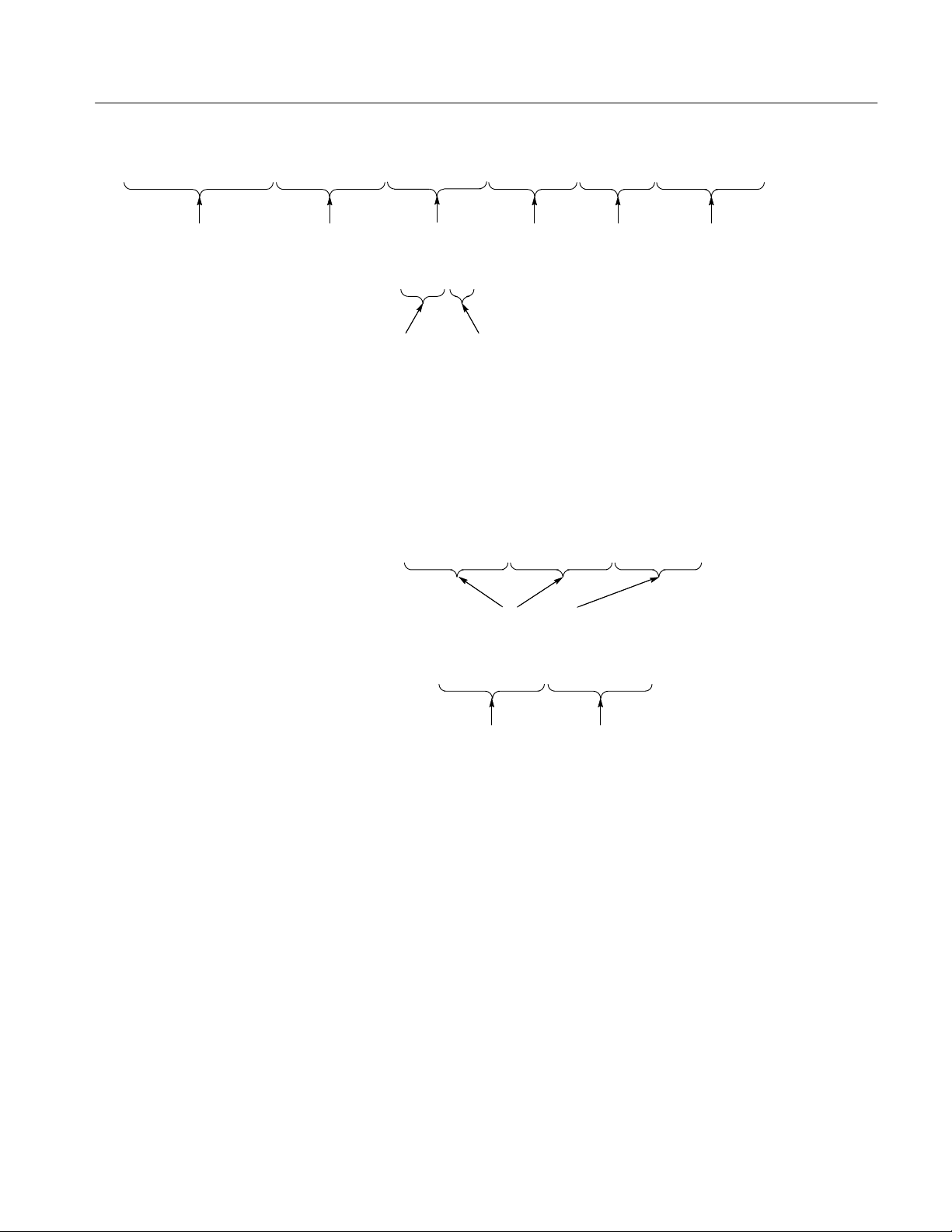
The SCPI language is based on a hierarchical or tree structure (see Figure 1–1)
that represents a subsystem. The top level of the tree is the root node; it is
followed by one or more lower-level nodes.
Creating Commands
Figure 1–1: Example of SCPI subsystem hierarchy tree
You can create commands and queries from these subsystem hierarchy trees.
Commands specify actions for the instrument to perform. Queries return
measurement data and information about parameter settings.
SCPI commands are created by stringing together the nodes of a subsystem
hierarchy and separating each node by a colon.
In Figure 1–1, OUTPUT is the root node and TTLTRG, STATE, POLARITY,
and SOURCE are lower-level nodes. To create a SCPI command, start with the
root node OUTPUT and move down the tree structure adding nodes until you
reach the end of a branch. Most commands and some queries have parameters;
you must include a value for these parameters. If you specify a parameter value
that is out of range, the parameter will be generally set to a default value. The
Root node
Lower-level
nodes
TVS600 & TVS600A Command Reference
1–1
Page 24

Command Syntax
command descriptions, which start on page 2–1, list the valid values for all
parameters.
For example, OUTPUT:TTLTRG1:STATE ON is a valid SCPI command created
from the hierarchy tree in Figure 1–1.
Creating Queries
Parameter Types
To create a query, start at the root node of a tree structure, move down to the end
of a branch, and add a question mark. OUTPUT:TTLTrg:STATe? is an example
of a valid SCPI query using the hierarchy tree in Figure 1–1.
Every parameter in the command and query descriptions is of a specified type.
The parameters are enclosed in brackets, such as <pattern>. The parameter type
is listed after the parameter and is enclosed in parentheses, for example,
(discrete). Some parameter types are defined specifically for the waveform
analyzer command set and some are defined by ANSI/IEEE 488.2-1992 (see
Table 1–1).
1–2
TVS600 & TVS600A Command Reference
Page 25

Command Syntax
T able 1–1: Parameter types used in syntax descriptions
Parameter Type Description Example
binary Binary numbers #B01 10
binary block
boolean Boolean numbers or values ON or 1
discrete A list of specific values HIGH, LOW, MID, PRBS23
hexadecimal
NR1
NR22 numeric Decimal numbers 1.2, 3.141516, –6.5
NR32 numeric Floating point numbers 3.1415E–9, –16.1E5
1
A specified length of binary data #512234xxxxx . . . where 5
indicates that the following 5
digits (12234) specify the length
of the data in bytes; xxxxx ...
indicates the binary data
OFF or 0
2
Hexadecimal numbers
#HAA, #H1
(0–9, A, B, C, D, E, F)
2,3
numeric Integers 0, 1, 15, –1
NRf2 numeric Flexible decimal number that
See NR1, NR2, NR3 examples
may be type NR1, NR2 or NR3
4
string
Alphanumeric characters (must
“Testing 1, 2, 3”
be within quotation marks)
1
Defined in ANSI/IEEE 488.2 as “Definite Length Arbitrary Block Response Data.”
2
An ANSI/IEEE 488.2–1992-defined parameter type.
3
Some commands and queries will accept a hexadecimal value even though the
parameter type is defined as NR1.
4
Defined in ANSI/IEEE 488.2 as “String Response Data.”
TVS600 & TVS600A Command Reference
1–3
Page 26

Command Syntax
Abbreviating Commands,
Queries, and Parameters
You can abbreviate most SCPI commands, queries, and parameters to an
accepted short form. This manual shows these short forms as a combination of
upper and lower case letters. The upper case letters indicate the accepted short
form of a command. As shown in Figure 1–2, you can create a short form by
using only the upper case letters. The accepted short form and the long form are
equivalent and request the same action of the instrument.
Long form of a
command
Accepted short form
of a command and
parameter
Minimum information needed
for accepted short form
Figure 1–2: Example of abbreviating a command
NOTE. The numeric part of a command or query must always be included in the
accepted short form. In Figure 1–2, the “1” of “TTLTRG1” is always included
in the command or query.
Chaining Commands and
Queries
1–4
You can chain several commands or queries together into a single message. To
create a chained message, first create a command or query, add a semicolon (;),
and then add more commands or queries and semicolons until you are done. If
the command following a semicolon is a root node, precede it with a colon (:).
Figure 1–3 illustrates a chained message consisting of several commands and
queries. A semicolon is not required after the final end or query in a chained
message. Responses to any queries in your message are separated by semicolons.
TVS600 & TVS600A Command Reference
Page 27
Command Syntax
OUTPUT1:TTLT:POL INV;:TRIG:SOUR INT1;:TRIG:SLOP NEG;:TRIG:LEV -2;:SWE:TINT?;:STAT:OPER:COND?
First command Command Command Second query
The response from this chained
message might be
Response from first query Response from second query
Command
1.0E-6;1536
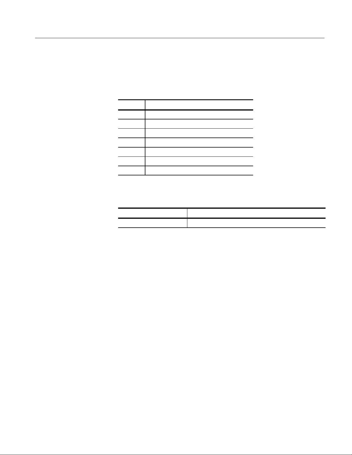
Figure 1–3: Example of chaining commands and queries
If a command or query has the same root and lower-level nodes as the previous
command or query, you can omit these nodes. In Figure 1–4, the second
command has the same root node (TRIG) as the first command, so these nodes
can be omitted.
TRIG:SOUR INT1;:TRIG:SLOP NEG;:TRIG:LEV -2
Identical root and lower-level nodes
TRIG:SOUR INT1;SLOP NEG;LEV -2
First query
Figure 1–4: Example of omitting root and lower-level nodes in chained message
General Rules
Here are some general rules for using SCPI commands, queries, and parameters:
You can use single (‘ ’) or double (“ ”) quotation marks for quoted strings,
but you cannot use both types of quotation marks for the same string.
correct: “This string uses quotation marks correctly.”
correct: ‘This string also uses quotation marks correctly.’
incorrect: “This string does not use quotation marks correctly.’
TVS600 & TVS600A Command Reference
First command Additional commands
(omitted the root nodes)
1–5
Page 28

Command Syntax
You can use upper case, lower case, or a mixture of both cases for all
commands, queries, and parameters.
OUTPUT1:TTLTRG:POLARITY INVERTED
is the same as
output1:ttltrg:polarity inverted
and
OUTPUT1:ttltrg:polarity INVERTED
No embedded spaces are allowed between or within nodes.
correct: OUTPUT1:TTLTRG:POLARITY INVERTED
incorrect: OUTPUT1: TTLTRG: POLARITY INV ERTED
IEEE 488.2 Common Commands
Description
Command and Query
Structure
ANSI/IEEE Standard 488.2 defines the codes, formats, protocols, and usage of
common commands and queries used on the interface between the controller and
the instruments. The waveform analyzer complies with this standard.
The syntax for an IEEE 488.2 common command is an asterisk (*) followed by a
command and, optionally, a space and parameter value. The syntax for an
IEEE 488.2 common query is an asterisk (*) followed by a query and a question
mark. All of the common commands and queries are listed in the last part of the
Syntax and Commands section. The following are examples of common
commands:
*ESE 16
*CLS
The following are examples of common queries:
*ESR?
*IDN?
1–6
TVS600 & TVS600A Command Reference
Page 29
Command Syntax
Backus-Naur Form
Definition
Message Terminators
This manual may describe commands and queries using the Backus-Naur Form
(BNF) notation. Table 1–2 defines the standard BNF symbols:
T able 1–2: BNF symbols and meanings
Symbol Meaning
<ą> Defined element
::= Is defined as
| Exclusive OR
{ą} Group; one element is required
[ą] Optional; can be omitted
.ă.Ă. Previous element(s) may be repeated
(ą) Comment
This manual uses <EOM> (End of message) to represent a message terminator.
Symbol Meaning
<EOM> Message terminator
The end-of-message terminator may be the END message (EOI asserted
concurrently with the last data byte), the ASCII code for line feed (LF) sent as
the last data byte, or both. The waveform analyzer always terminates messages
with LF and EOI. It allows white space before the terminator.
Constructed Mnemonics
Some header mnemonics specify one of a range of mnemonics. For example, a
channel mnemonic can be either INP1, INP2, INP3, or INP4. You use these
mnemonics in the command just as you do any other mnemonic. For example,
there is a INP1:FILT command, and there is also an INP2:FILT command. In the
command descriptions, this list of choices is abbreviated as INP<n>.
TVS600 & TVS600A Command Reference
1–7
Page 30

Command Syntax
Block Arguments
Several waveform analyzer commands use a block argument form:
Symbol Meaning
<NZDig> A non-zero digit character, in the range 1–9
<Dig> A digit character, in the range 0–9
<DChar> A character with the hex equivalent of 00 through FF
hexadecimal (0 through 255 decimal)
<Block> A block of data bytes, defined as:
<Block> ::=
{ #<NZDig><Dig>[<Dig>...][<DChar>...]
| #0[<DChar>...]<terminator> }
<NZDig> specifies the number of <Dig> elements that follow. Taken together, the
<Dig> elements form a decimal integer that specifies how many <DChar>
elements follow. The #0 format is for blocks of indifinite length and an END
message termination is required.
1–8
TVS600 & TVS600A Command Reference
Page 31

Commands
Page 32

Page 33

Commands
Overview
This section describes each command and query in the waveform analyzer. The
commands are organized by subsystem groups and the commands in each group
are in alphabetical order. In Figure 2–1, each block is a root node and the
commands within a block are subsystems. For example, SENSe is a root node
and AVERage is a subsystem of the SENSe node.
[SENSe:]
CH1..4
INPut1..4 VOLTage1..4
MISC:
CALibration
FORMat
MEMory
OUTPut
STATus
SYSTem
TEST
IEEE 488.2
ABORt
INITiate
SWEep
ROSCillator
AVERage
AADVance
TRIGger
Idle
ARM
TRIGger[:A]
FUNCtion
DATA
TRACe
AATS
CHAN1..4
CALC1..4
CALCulate1..4
TRIGger:B
Figure 2–1: Instrument model showing root-level nodes and subsystems
TVS600 & TVS600A Command Reference
2–1
Page 34

Commands
2–2
TVS600 & TVS600A Command Reference
Page 35

AADVance Subsystem
This section describes the commands in the [SENSe:]AADVance subsystem. See
Figure 2–2. These commands control how auto-advance acquisition records are
acquired and transferred to a VXIbus controller. A functional model of the
AADVance subsystem is shown in Figure 2–3.
Figure 2–2: AADVance subsystem hierarchy
SENSe
CH 1
CH 2
INPut[1]
INPut2 :VOLTage2
:VOLTage[1]
:SWEep
:DET ector
:ROSCillator
Figure 2–3: AADVance subsystem functional model
:AVERage
:AADVance
:FUNCtion
:DATA
TVS600 & TVS600A Command Reference
2–3
Page 36

AADVance Subsystem
AADVance AADVance?
Sets or queries the state of the auto-advance acquisition mode. In the auto-advance mode the waveform analyzer acquires a sequence of data records for each
active channel. The delay between one acquisition record and the next one is
very short and is due only to the minimal re-arm time and any trigger holdoff
you set. Use the command AADVance:COUNt to set the number of records to
acquire. You cannot use acquisition modes average, envelope, or peak detect (set
using [SENSe:]AVERage command) when using the auto-advance acquisition
mode.
The auto-advance mode of acquisition affects all enabled channels (XTIM:VOLT
<n>). You cannot acquire one channel in the auto-advance mode and acquire
another with the normal acquisition mode.
Syntax
Parameters
Reset Value
Errors and Events
Dependencies
Examples
[SENSe:]AADVance[:STATe] <boolean>
[SENSe:]AADVance[:STATe]?
<boolean> Query response
<NRf>
1 or ON
0 or OFF
0
None
Enabling auto-advance acquisition disables [SENSe:]AVERage acquisition,
ENVelope or SCALar type.
Command: AADV ON
Query: AADV?
Response: 1
<NF1>
1
0
2–4
Related Commands
AADVance:COUNt
AVERage
TVS600 & TVS600A Command Reference
Page 37

AADVance:COUNt AADVance:COUNt?
AADVance Subsystem
Sets or queries the number of records to acquire in the auto-advance acquisition
mode. The maximum number of Auto-advance records that you can acquire
depends on the record length and the number of active channels. A setting of
zero (0) acquires enough records to fill the DSP memory, regardless of the
current acquisition system settings. MAXimum acquires enough records to fill
DSP memory based on the current acquisition settings. The distinction is that
with a change such as the number of active channels, the MAXimum COUNt
setting is not adjusted, whereas the zero COUNt setting adjusts to ensure
memory is just filled within the new conditions.
To determine the current value for MAX, first set all acquisition parameters. Set
AADV:COUN to MAX. Finally, query with AADV:COUN? to return the current
value for MAX.
Syntax
Parameters
Reset Value
Errors and Events
Dependencies
Examples
[SENSe:]AADVance:COUNt <count>
[SENSe:]AADVance:COUNt?
<count> Query response
<NRf>
0 (Fill acquisition memory)
1 to MAX (Acquire number)
MINimum
MAXimum
1
Execution Error –222, “Data out of range”
Attempted to set count to an illegal value.
None
Command: AADV:COUN 100
<NR1>
1
<depends on configuration>
Query: AADV:COUN?
Response: 100
Related Commands
TVS600 & TVS600A Command Reference
AADVance
2–5
Page 38

AADVance Subsystem
AADVance:RECord:COUNt AADVance:RECord:COUNt?
Sets or queries the number of auto-advance acquisition records to transfer in
response to the commands DATA?, TRACe?, TRACe:COPY?, or
TRACe:LIST?. The maximum :COUNt value depends on the number of
acquired records and the value of AADVance:RECord:STARt. A setting of
zero (0) selects all acquisition records, beginning with :STARt, for transfer
regardless of the current acquisition system settings. MAXimum selects all
acquisition records for transfer based on the current acquisition settings. If you
change a setting, such as the number of active channels, the MAXimum setting
will not be adjusted, but a setting of zero will automatically adjust for the new
acquisition settings.
Syntax
Parameters
Reset Value
Errors and Events
Dependencies
Examples
[SENSe:]AADVance:RECord:COUNt <count>
[SENSe:]AADVance:RECord:COUNt?
<count> Query response
<NRf>
0 (Transfer all records)
1 to MAX (Transfer number of
records)
MINimum
MAXimum
1
Execution Error –222, “Data out of range”
Attempted to set count to an illegal value.
None
Command: AADV:REC:COUN 100
<NR1>
1
<depends on configuration>
2–6
Related Commands
Query: AADV:REC:COUN?
Response: 100
AADVance
AADVance:COUNt
AADVance:RECord:STARt
CALC:AAML
TVS600 & TVS600A Command Reference
Page 39

AADVance:RECord:STARt AADVance:RECord:STARt?
Sets or queries the number of the first auto-advance waveform record to transfer
in response to the commands DATA?, TRACe?, and TRACe:COPY?. The
maximum :STARt value depends on the number of acquired records. A setting of
zero (0) selects the last waveform record for transfer. Negative settings select
waveform records referenced from the last one, the zero record. For example, the
–1 record is the second from last and the –2 record is third from last.
Note that auto-advance acquisition always starts with record number one.
AADVance Subsystem
Syntax
Parameters
Reset Value
Errors and Events
Dependencies
[SENSe:]AADVance:RECord:STARt <start>
[SENSe:]AADVance:RECord:STARt?
<start> Query response
<NRf>
–MAX + 1 to –1 (Number before last
record)
0 (Last record)
1 to MAX (Number from first record)
MINimum
MAXimum
1
Execution Error –222, “Data out of range”
Attempted to set start to an illegal value.
None
<NR1>
1
<depends on configuration>
Examples
Related Commands
TVS600 & TVS600A Command Reference
Command: AADV:REC:STAR 100
Query: AADV:REC:STAR?
Response: 100
AADVance
AADVance:COUNt
AADVance:RECord:COUNt
CALC:AAML
2–7
Page 40

AADVance Subsystem
2–8
TVS600 & TVS600A Command Reference
Page 41

ARM Subsystem
This section describes the commands in the ARM subsystem. See Figure 2–4.
These commands operate with the TRIGger, INITiate, and ABORt subsystems to
trigger acquisitions.
ARM
[:A | :SEQuence[1]]
:DEFine?
:COUNt
[:LAYer[1]]
:SOURce
Figure 2–4: ARM subsystem hierarchy
TVS600 & TVS600A Command Reference
2–9
Page 42

ARM Subsystem
ARM:DEFine? (Query Only)
Returns the predefined SEQuence1 alias. :A is a pre-defined alias for :SEQuence[1]. The commands ARM:DEFine? and TRIGger:DEFine? are aliases
which produce the same result.
Syntax
Parameters
Reset Value
Errors and Events
Dependencies
Examples
Related Commands
ARM[:SEQuence[1]]:DEFine?
<sequence_alias> Query response
Not applicable <string>
“A”
“A”
None
None
Query: ARM:DEF?
Response: "A"
TRIGger:DEFine?
TRIGger:SEQuence2:DEFine?
2–10
TVS600 & TVS600A Command Reference
Page 43

ARM:SOURce ARM:SOURce?
ARM Subsystem
Sets or queries the source that will arm the acquisition system. You can specify
only one source at a time and it is shared by all acquired channels. Setting the
arm source to BUS configures the event detector to accept and arm on either the
*TRG or the VXIbus word serial <Trigger> command. The ECLTrg and TTLTrg
sources provide normal and inverted access to the standard ECLT and TTLT
signals on the VXI P2 bus. TTLTrg<n> arms when the TTLT line is low.
ITTLTrg<n> arms when the TTLT line is high. The ECLTrg<n> arms when the
ECLT line is high. IECLTrg<n> arms when the ECLT line is low. EXT arms
when the EXT input is a TTL low.
EXTernal is the front-panel BNC connector labeled Arm Input. Setting the arm
source to IMMediate bypasses event detection and immediately arms the
acquisition system.
Syntax
Parameters
ARM[:A][:LAYer[1]]:SOURce <arm_source>
ARM[:A][:LAYer[1]]:SOURce?
<arm_source> Query response
BUS
ECL T rg0
ECL T rg1
EXTernal
IECL T rg0
IECL T rg1
ITTL T rg0
ITTL T rg1
.
.
.
ITTL T rg7
IMMediate (No source needed)
TTL Trg0
TTL Trg1
.
.
.
TTL Trg7
BUS
ECL T0
ECL T1
EXT
IECL Trg0
IECL Trg1
ITTL Trg0
ITTL Trg1
.
.
.
ITTL Trg7
IMM
TTL T0
TTL T1
.
.
.
TTL T7
Reset Value
Errors and Events
IMM
Execution Error –141, “Invalid character data”
Attempted to set arm source to INTernal or any other invalid value.
TVS600 & TVS600A Command Reference
2–11
Page 44

ARM Subsystem
Execution Error –212, “Arm ignored”
Sent *TRG or the VXIbus word serial <Trigger> command when ARM:SOURce
is not set to BUS or when the instrument is not waiting at the ARM Event
Detection layer.
Execution Error –215, “Arm deadlock”
Attempted to query the instrument when arm source is set to BUS and before
sending *TRG or the VXIbus word serial <Trigger> command.
Dependencies
Examples
Related Commands
None
Command: ARM:SOUR TTLTRG0
Query: ARM:SOUR?
Response: TTLT0
TRIGger:SOURce
2–12
TVS600 & TVS600A Command Reference
Page 45

AVERage Subsystem
This section describes the commands in the [SENSe:]AVERage subsystem. See
Figure 2–5. These commands select and setup one of four acquisition modes:
normal, average, envelope, and peak detect. (Peak detect is available for
TVS600A models only.) All active channels are affected by the acquisition mode
selected. Averaging, peak detecting, and enveloping occur in the acquisition
system before waveform records are passed to the CALC blocks. See Figure 2–6.
[:STATe] :COUNt :TYPE
Figure 2–5: A VERage subsystem hierarchy
SENSe
[SENSe:]
AVERage
CH 1
CH 2
INPut[1]
INPut2
:VOLTage[1]
:SWEep
:DET ector
:ROSCillator
:VOLTage2
Figure 2–6: AVERage subsystem functional model
:AVERage
:AADVance
:FUNCtion
:DATA
TVS600 & TVS600A Command Reference
2–13
Page 46

AVERage Subsystem
AVERage AVERage?
Sets or queries whether the waveform analyzer performs averaging during
acquisition. When the setting is off, the aquisition mode is normal; when on, the
acquisition mode is either average, envelope or peak detect, depending on the
setting for AVERage:TYPE (see page 2–16). The AVERage setting affects all
channels. When averaging is on, the values returned from [SENSe:]DATA? are
averaged, enveloped or peak-detected. The raw, unaveraged data is not available.
Syntax
Parameters
Reset Value
Errors and Events
Dependencies
Examples
[SENSe:]AVERage[:STATe] <boolean>
[SENSe:]AVERage[:STATe]?
<boolean> Query response
<NRf>
N ≠ 0 or ON
0 or OFF
0
None
Enabling averaging sets AADVance to OFF.
Command: AVER ON
Query: AVER?
Response: 1
<NF1>
1
0
2–14
Related Commands
AVERage:COUNt
AVERage:TYPE
AADVance
TVS600 & TVS600A Command Reference
Page 47

AVERage:COUNt AVERage:COUNt?
AVERage Subsystem
Sets or queries the number of acquisition records to average. Averaging reduces
signal noise by approximately 3 dB for each power of 2 increase (2, 4, 8, 16) in
the value of COUNt. For example, a COUNt setting of 8 will result in 3 dB less
noise than a COUNt of 4. The COUNt setting affects all active channels. The
count setting of one is intended for the PEAK DET type of averaging. PEAK
DET uses hardware to envelope the acquired data. The other modes will function
with a count of one, but with no added value.
Syntax
Parameters
Reset Value
Errors and Events
Dependencies
Examples
[SENSe:]AVERage:COUNt <count>
[SENSe:]AVERage:COUNt?
<count> Query response
<NRf>
1 ≤ N ≤ 4096
MINimum
MAXimum
1
TVS600A only
2
Execution Error –222, “Data out of range”
Attempted to set count to an illegal value.
None
Command: AVER:COUN 16
<NR1>
1
2, 1
4096
Query: AVER:COUN?
Response: 16
Related Commands
TVS600 & TVS600A Command Reference
AVERage
AVERage:TYPE
2–15
Page 48

AVERage Subsystem
AVERage:TYPE AVERage:TYPE?
Sets or queries the mode of acquisition to perform:
SCALar (average), the default, averages each new sample point with the
corresponding point in the previous acquisition record.
ENVelope generates a waveform record of interleaved MAX/MIN pairs of
sample points (the number of pairs is SWEep:POINts divided by two).
PEAKdetect (TVS600A only) generates an array of MAX/MIN pairs, but
uses hardware peak detect to capture glitches between sampling intervals.
The AVERage:TYPE setting affects all channels.
Peak Detect hardware is not functional at a sample rate faster than 100 MS/s.
When peak detect is enabled on rates faster than 100 MS/s, the instrument will
function as if in ENVelope mode and will not issue any warning or error to that
effect.
Syntax
Parameters
[SENSe:]AVERage:TYPE <type>
[SENSe:]AVERage:TYPE?
<type> Query response
ENVelope
SCALar
PEAKdetect
1
TVS600A only
1
ENV
SCAL
PEAK
1
2–16
TVS600 & TVS600A Command Reference
Page 49

AVERage Subsystem
Reset Value
Errors and Events
Dependencies
Examples
Related Commands
SCAL
Command Error –141, ”Invalid character data”
Attempted to set average type to an illegal value.
None
Command:
Query:
Response:
AVERage
AVERage:COUNt
TVS600 & TVS600A Command Reference
2–17
Page 50

AVERage Subsystem
2–18
TVS600 & TVS600A Command Reference
Page 51

CALCulate Subsystem
This section describes the commands in the CALCulate subsystems which
process and perform measurements on acquisition records. These calculations are
typically performed immediately after the waveform analyzer completes
acquisition of the source. You can use CALCulate:IMMediate to reprocess and
measure an existing acquisition record. Figures 2–7 and 2–8 show the command
subblocks in the CALCulate subsystem.
For a description of how to process waveforms and make measurements with the
commands in the CALCulate subsystem, refer to the TVS600 & TVS600A Series
Waveform Analyzers User Manual.
CALCulate
:AAMList
:DERivative
:FILTer
:FORMat
:INTegral
:SMOothing
:TRANsform
:WMList
:FEED1<CALC SubĆblocks>
:FEED2
:CONTEXT
:IMMediate :PATH :WMParameter:DATA?
Figure 2–7: CALCulate subsystem hierarchy
...:EXPRession:PREamble?
TVS600 & TVS600A Command Reference
2–19
Page 52

CALCulate Subsystem
CALCulate1..4
SENSe
AATS
”XTIM:VOLT n”
TRACe
CHAN1..4
:FEED1
:FEED2
Figure 2–8: CALCulate subsystem functional model
CALCulate:AAMList CALCulate:AAMList?
Sets or queries the list of measurements to perform on the selected auto-advance
acquisition records. You can specify up to 50 measurements by separating them
with commas. Before you can make auto-advance measurements, you must
enable the auto-advance measurement system with the command CALCulate:AAMList:STATe.
:PA TH
TRACe
CALC1..4
”CALCn”
:PA TH:EXPRession
2–20
Syntax
Parameters
Specify the measurement methods and reference values with the
CALC:WMParameter commands.
The records on which measurements are made are specified by the
AADV:REC:STARt and AADV:REC:COUNt commands.
CALCulate<n>:AAMList <list>
CALCulate<n>:AAMList?
1
<n>
1
2
3
4
1
The calculate block number <n> selects one of four calculate blocks. If you omit <n>,
the default is calculate block 1.
Query response
NA
TVS600 & TVS600A Command Reference
Page 53

<list> Query response
AMPLitude AMPL
AREA AREA
CARea CAR
CMEan CME
COPulse
CP ARea
1
1
COP
CP AR
CRMS CRMS
CROSs CROSs
DELay DEL
FREQuency FREQ
FTIMe FTIM
GAIN GAIN
HIGH HIGH
LOW LOW
MAXimum MAX
MEAN | DC MEAN
MID MID
MINimum MIN
NCRoss NCR
NDUTycycle NDUT
NWIDth NWID
OVERshoot
PARea
1
1
OVER
PAR
PCRoss PCR
PERiod PER
PDUTycycle PDUT
PHAse PHA
PREShoot
1
PRES
PTPeak PTP
PWIDth PWID
RMS | AC RMS
RTIMe RTIM
SDEViation SDEV
TTRig TTR
1
TVS600A products only.
CALCulate Subsystem
TVS600 & TVS600A Command Reference
2–21
Page 54

CALCulate Subsystem
Reset Value
Errors and Events
Dependencies
Examples
Related Commands
MEAN
Command Error 108, “Parameter not allowed”
Attempted to assign more than 50 measurements to the list.
Execution Error –141, “Invalid character data”
Attempted to program an illegal waveform measurement.
None
Command: CALC1:AAML RTIM,FTIM,PWID
Query: CALC1:AAML?
Response: RTIM,FTIM,PWID
CALCulate:AAMList:STATe
AADV:REC:STARt
AADV:REC:COUNt
2–22
TVS600 & TVS600A Command Reference
Page 55

CALCulate:AAMList:STATe CALCulate:AAMList:STATe?
Sets or queries whether to perform waveform measurement(s) on acquisition
records captured with auto-advance acquisition. You specify Auto Advance
measurements with the CALCulate:AAMList command.
CALCulate Subsystem
Syntax
Parameters
Reset Value
CALCulate<n>:AAMList:STATe <boolean>
CALCulate<n>:AAMList:STATe?
1
<n>
1
2
3
4
1
The calculate block number <n> selects one of four calculate blocks. If you omit <n>,
the default is calculate block 1.
<boolean> Query response
<NRf>
1 or ON
0 or OFF
Query response
Not applicable
<NF1>
1
0
0
Errors and Events
Dependencies
None
The setting for :STATe is ignored when you use the command CALC:PATH:EXPRession.
Examples
Command: CALC:AAML:STAT ON
Query: CALC:AAML:STAT?
Response: 1
Related Commands
CALCulate:AAMList
SWEep:ADDV ON|OFF
TVS600 & TVS600A Command Reference
2–23
Page 56

CALCulate Subsystem
CALCulate:DATA? (Query Only)
This query returns the results of waveform processing and measurement
functions performed on acquired waveform records. The default format of the
returned data is ASCII. However, you can set the data format with the
FORMat:CALCulate command.
Results are returned only when pending acquisitions and calculations are
complete. The synchronizing commands *WAI, *OPC, and *OPC? are not
required unless you wish to synchronize the transfer differently.
The CALCulate and TRACe subsystems use consistent naming, such that
CALC1:DATA? is equivalent to TRAC? CALC1.
Syntax
Parameters
Reset Value
Errors and Events
Dependencies
Examples
CALCulate<n>:DATA?
1
<n>
1
2
3
4
1
The calculate block number <n> selects one of four calculate blocks. If you omit <n>,
the default is calculate block 1.
Query response
Not applicable
Not applicable
Execution Error –230, “Data corrupt or stale”
Attempted to query data that is invalid, incomplete or stale.
None
Query: CALC1:DATA?
2–24
Related Commands
Response: <arb_block_data>
[SENSe:]DATA?
[SENSe:]DATA:PREamble?
CALCulate:DATA:PREamble?
TRACe?
TRACe:PREamble?
TVS600 & TVS600A Command Reference
Page 57

CALCulate:DATA:PREamble? (Query Only)
Returns the data preamble for acquisition record processing and measurement
functions. Results are returned only when pending acquisitions and calculations
are complete. The default format of the returned data is ASCII. However, you
can set the data format with the FORMat:CALCulate command. The synchronizing commands *WAI, *OPC, and *OPC? are not required unless you wish to
synchronize the transfer differently.
The CALCulate and TRACe subsystems use consistent naming, such that
CALC1:DATA? is equivalent to TRAC? CALC1.
CALCulate Subsystem
Syntax
Parameters
Reset Value
Errors and Events
Dependencies
Examples
CALCulate<n>:DATA:PREamble?
1
<n>
1
2
3
4
1
The calculate block number <n> selects one of four calculate blocks. If you omit <n>,
the default is calculate block 1.
Query response
Not applicable
Not applicable
Execution Error –230, “Data corrupt or stale”
Attempted to query the preamble for data that is invalid, incomplete or stale.
None
Query: CALC1:DATA:PRE?
Response: (DIF Expression)
Related Commands
[SENSe:]DATA?
[SENSe:]DATA:PREamble?
CALCulate:DATA?
TRACe?
TRACe:PREamble?
TVS600 & TVS600A Command Reference
2–25
Page 58

CALCulate Subsystem
CALCulate:DERivative:STATe CALCulate:DERivative:STATe?
Sets or queries whether to calculate a post-acquisition derivative on the selected
channel. When ON, the waveform analyzer calculates the derivative for every
point in an acquisition record. The result is a CALC<n> data record with the
same number of points as the original acquisition record.
When you perform a calculation with the command CALC:PATH:EXPRession,
the value of :STATe is ignored.
Syntax
Parameters
Reset Value
CALCulate<n>:DERivative:STATe<boolean>
CALCulate<n>:DERivative:STATe?
1
<n>
1
2
3
4
1
The calculate block number <n> selects one of four calculate blocks. If you omit <n>,
the default is calculate block 1.
<boolean> (DERivative state) Query response
<NRf>
1 or ON
0 or OFF
Query response
Not applicable
<NR1>
1
0
0
2–26
Errors and Events
Dependencies
Examples
Related Commands
None
None
Command: CALC1:DER:STAT ON
Query: CALC1:DER:STAT?
Response: 1
CALCulate:INTegral:ST ATe
TVS600 & TVS600A Command Reference
Page 59

CALCulate:FEED[1] CALCulate:FEED[1]?
CALCulate Subsystem
Sets or queries the source of data for the specified CALCulate block. The
calculations you set for a CALC block are performed on the source chosen with
this command when using the CALC:PATH command. The source may be from
any channel, reference, or a SENSe function; it is not tied to the CALC block
number. For example, the FEED1 for CALC2 could be “XTIM:VOLT 1” or
“XTIM:VOLT 3.” Additionally, more than one CALC block can operate on the
same source.
Trace names and function strings may be used interchangeably for the source
parameter <sense_func>. The query form always returns the function strings.
When you perform a calculation with the command CALC:PATH:EXPRession,
the value of :FEED1 can be referenced as “%1” (or by name; CHAN1, for
example) within the expression. Calculations are not performed on the :FEED1
source unless explicitly referenced in the CALC expression. See CALC:PATH
and CALC:PATH:EXPR commands.
Syntax
Parameters
When specifying calculations that require more than one waveform, such as gain,
phase, or delay, :FEED1 specifies the reference waveform and :FEED2 specifies
the target waveform. The target waveform is measured with respect to the
reference waveform; for example,1V in :FEED2 measured with respect to 2V in
:FEED1 yields a gain (attenuation) of .5.
CALCulate<n>:FEED[1] <sense_func>
CALCulate<n>:FEED[1]?
1
<n>
1
2
3
4
1
The calculate block number <n> selects one of four calculate blocks. If you omit <n>,
the default is calculate block 1.
Query response
Not applicable
TVS600 & TVS600A Command Reference
2–27
Page 60

CALCulate Subsystem
<sense_func> (CALC block source) Query response
<string>
“XTIMe:VOL Tage[:DC] 1” or CHAN1
“XTIMe:VOL Tage[:DC] 2” or CHAN2
“XTIMe:VOL Tage[:DC] 3” or CHAN3
“XTIMe:VOL Tage[:DC] 4” or CHAN4
<string>
“XTIM:VOLT 1”
“XTIM:VOLT 2”
“XTIM:VOLT 3”
“XTIM:VOLT 4”
Reset Value
Errors and Events
Dependencies
“REFerence1” or REF1
“REFerence2” or REF2
...
“REFerence10” or REF10
“ ” or NONE
“REF1”
“REF2”
...
“REF10”
“ ”
" (None)
Execution Error –141, “CALC1:FEED FTM”
Attempted to set FEED1 to an invalid trace name.
Execution Error –224, “Illegal parameter value, invalid sense function”
Attempted to set FEED1 to an invalid sense function.
Execution Error –241, “Hardware missing”
Attempted to set feed to “XTIM:VOLT 3” or “XTIM:VOLT 4” when the
instrument is configured with two channels.
None
Examples
Related Commands
CALCulate:FEED2 CALCulate:FEED2?
2–28
Command: CALC1:FEED1 XTIM:VOLT 1"
Query: CALC1:FEED1?
Response: "XTIM:VOLT 1"
CALCulate:PATH
Sets or queries a second source of data for the specified CALCulate block. The
second source is used when measurements that are based on two waveforms,
such as gain, phase, and delay, are specified using the CALCulate:WMList
command.
TVS600 & TVS600A Command Reference
Page 61

CALCulate Subsystem
The source may be from any channel, reference or a SENSe function, it is not
tied to the CALC block number. For example, the FEED2 for CALC2 could be
“XTIM:VOLT 1” or “XTIM:VOLT 3.” Additionally, more than one CALC block
can operate on the same source.
Trace names and function strings may be used interchangeably for the source
parameter <sense_func>. The query form always returns the function strings.
When you perform a calculation with the command CALC:PATH:EXPRession,
the value of :FEED2 can be referenced as “%2” within the expression.
When defining SCPI model calculations that measure parameters based on two
waveforms (such as Gain and Delay), :FEED1 specifies the reference waveform
and :FEED2 specifies the target waveform. Also, the functions you set using
CALC:PATH only apply to the data source selected with FEED1. The source
selected by FEED2 is unaffected by the functions you select.
Syntax
Parameters
CALCulate<n>:FEED2 <sense_func>
CALCulate<n>:FEED2?
1
<n>
1
2
3
4
1
The calculate block number <n> selects one of four calculate blocks. If you omit <n>,
the default is calculate block 1.
<sense_func> (CALC block source) Query response
<string>
“XTIMe:VOL Tage[:DC] 1” or CHAN1
“XTIMe:VOL Tage[:DC] 2” or CHAN2
“XTIMe:VOL Tage[:DC] 3” or CHAN3
“XTIMe:VOL Tage[:DC] 4” or CHAN4
“REFerence1” or REF1
“REFerence2” or REF2
....
“REFerence10” or REF10
Query response
Not applicable
<string>
“XTIM:VOLT 1”
“XTIM:VOLT 2”
“XTIM:VOLT 3”
“XTIM:VOLT 4”
“REF1”
“REF2”
...
“REF10”
“ ” or NONE
1
Specifying NONE causes :FEED2 to default to the same source as :FEED1. If you
specify NONE, the same waveform will be used for taking the gain, phase, or delay
measurement.
TVS600 & TVS600A Command Reference
1
“” (empty string returned)
2–29
Page 62

CALCulate Subsystem
Reset Value
Errors and Events
Dependencies
Examples
Related Commands
" (NONE)
Execution Error –141, “CALC1:FEED2 FTM”
Attempted to set FEED2 to an invalid trace name.
Execution Error –224, “Illegal parameter value, invalid sense function”
Attempted to set FEED2 to an invalid sense function.
Execution Error –241, “Hardware missing”
Attempted to set feed to “XTIM:VOLT 3” or “XTIM:VOLT 4” when the
instrument is configured with two channels.
None
Command: CALC1:FEED2 XTIM:VOLT 1"
Query: CALC1:FEED2?
Response: "XTIM:VOLT 1"
CALCulate:PATH
CALCulate:FEED2:CONText CALCulate:FEED2:CONText?
Sets or queries the measurement parameter block, one of CALC1–CALC4, used
to characterize the FEED2 data.
Any of the four CALC blocks, CALC1–CALC4, may be used interchangeably
for the context parameter <calc_block>.
Syntax
CALCulate<n>:FEED2:CONText <calc_block>
CALCulate<n>:FEED2:CONText?
2–30
TVS600 & TVS600A Command Reference
Page 63

CALCulate Subsystem
Parameters
Reset Values
Errors and Events
<calc_block> (CALC block source) Query response
CALC1
CALC2
CALC3
CALC4
WMP1
WMP2
WMP3
WMP4
Context Value
CALC1:FEED2:CONT
CALC2:FEED2:CONT
CALC3:FEED2:CONT
CALC4:FEED2:CONT
CALC1
CALC2
CALC3
CALC4
WMP1
WMP2
WMP3
WMP4
CALC1
CALC2
CALC3
CALC4
Execution Error –141, “Invalid character data,
CALC1:FEED2:CONT FTM”
Attempted to set FEED2:CONT to an invalid parameter value.
Dependencies
Examples
Related Commands
None
Command: CALC1:FEED2:CONT CALC4
Query: CALC1:FEED2:CONT?
Response: CALC4
CALCulate:FEED1
CALCulate:FEED2
TVS600 & TVS600A Command Reference
2–31
Page 64

CALCulate Subsystem
CALCulate:FILTer:FREQuency[:TYPE] CALCulate:FILTer:FREQuency[:TYPE]?
Sets or queries the type of FREQuency filtering to perform on an acquisition
record.
The available filter types are as follows:
BPASs—rejects frequency components outside the defined frequency range.
NOTCh—rejects frequency components within a defined frequency range.
HPASs—rejects frequency components below a specified frequency.
LPASs—rejects frequency components above a specified frequency.
When you set :TYPE to bandpass or notch, set the filter parameters with the
:FILTer:FREQuency commands STARt, STOP, CENTer, and SPAN. When you
set :TYPE to high pass or low pass, set the filter parameters with the commands
HPASs or LPASs. For an overview of the measurement system, refer to the
TVS600 & TVS600A User Manual.
Syntax
Parameters
Reset Value
CALCulate<n>:FILTer[:GATE]:FREQuency[:TYPE] <type>
CALCulate<n>:FILTer[:GATE]:FREQuency[:TYPE]?
1
<n>
1
2
3
4
1
The calculate block number <n> selects one of four calculate blocks. If you omit <n>,
the default is calculate block 1.
<type> (Frequency filter) Query response
BP ASs
HP ASs
LP ASs
NOTCh
Query response
Not applicable
BP AS
HP AS
LP AS
NOTC
BPAS
2–32
Errors and Events
Execution Error –141, “Invalid character data”
Attempted to set type to an illegal value.
TVS600 & TVS600A Command Reference
Page 65

CALCulate Subsystem
Dependencies
Examples
Related Commands
None
Command: CALC1:FILT:FREQ NOTCH
Query: CALC1:FILT:FREQ?
Response: NOTC
CALCulate:FILTer:FREQuency:CENTer
CALCulate:FILTer:FREQuency:HPASs
CALCulate:FILTer:FREQuency:LPASs
CALCulate:FILTer:FREQuency:SPAN
CALCulate:FILTer:FREQuency:STARt
CALCulate:FILTer:FREQuency:STATe
CALCulate:FILTer:FREQuency:STOP
CALCulate:FILTer:FREQuency:CENTer CALCulate:FILTer:FREQuency:CENTer?
Sets or queries the center frequency of the bandpass or notch filter. Use the
command :FREQuency:SPAN to set the frequency range for :NOTCh and
BPASs frequency filters. For example, if you set :CENTer to 10 MHz and :SPAN
to 2 MHz, then the :NOTCh filter will have a range of 9 MHz
to 11 MHz. For an overview of the measurement system, refer to the TVS600 &
TVS600A Series Waveform Analyzers User Manual.
Syntax
Parameters
TVS600 & TVS600A Command Reference
CALCulate<n>:FILTer[:GATE]:FREQuency:CENTer <center>
CALCulate<n>:FILTer[:GATE]:FREQuency:CENTer?
1
<n>
1
2
3
4
1
The calculate block number <n> selects one of four calculate blocks. If you omit <n>,
the default is calculate block 1.
Query response
Not applicable
2–33
Page 66

CALCulate Subsystem
Reset Value
Errors and Events
Dependencies
Examples
<center> (Center frequency of SPAN)
<NRf> <NR3>
1
The default multiplier for the <center> parameter is HZ for hertz. You can also use the
multipliers KHZ for kilohertz, MHZ for megahertz, and GHZ for gigahertz.
1
Query response
250.0E+6
Execution Error –222, “Data out of range”
Attempted to set center to an illegal value.
You can set the frequency range for the frequency filters :NOTCh and :BPASs
with either the command pair :CENTer and :SPAN or the command pair :STARt
and :STOP. Because both command pairs control the same parameters, changing
either command pair will affect the other.
Command: CALC1:FILT:FREQ:CENT 10E6
Query: CALC1:FILT:FREQ:CENT?
Response: 10.0E+6
Related Commands
CALCulate:FILTer:FREQuency:SPAN
2–34
TVS600 & TVS600A Command Reference
Page 67

CALCulate:FILTer:FREQuency:HPASs CALCulate:FILTer:FREQuency:HPASs?
Sets or queries the limit frequency (<cutoff>) below which the filter attenuates
all frequency components. The :HPASs frequency is ignored when you select the
bandpass, notch or low-pass filter. Use the command CALCulate:FILTer:FREQuency HPASs to enable the high-pass filter.
CALCulate Subsystem
Syntax
Parameters
Reset Value
CALCulate<n>:FILTer[:GATE]:FREQuency:HPASs <cutoffā>
CALCulate<n>:FILTer[:GATE]:FREQuency:HPASs?
1
<n>
1
2
3
4
1
The calculate block number <n> selects one of four calculate blocks. If you omit <n>,
the default is calculate block 1.
<cutoff> (Limit frequency)
<NRf> <NR3>
1
The default multiplier for the <cutoff> parameter is HZ for hertz. You can also use the
multipliers KHZ for kilohertz, MHZ for megahertz, and GHZ for gigahertz.
1
Query response
Not applicable
Query response
250.0E+6
Errors and Events
Execution Error –222, “Data out of range”
Attempted to set the high pass cutoff frequency to an illegal value.
Dependencies
Examples
None
Command: CALC1:FILT:FREQ:HPAS 10E6
Query: CALC1:FILT:FREQ:HPAS?
Response: 10.0E+6
Related Commands
CALCulate:FILTer:FREQuency:LPASs
TVS600 & TVS600A Command Reference
2–35
Page 68

CALCulate Subsystem
CALCulate:FILTer:FREQuency:LPASs CALCulate:FILTer:FREQuency:LPASs?
Sets or queries the limit frequency (<cutoff>) above which the filter attenuates
all frequency components. The :LPASs frequency is ignored when filter type is
set to bandpass, notch or high pass. Use the command CALCulate:FILTer:FREQuency LPASs to enable the low-pass filter.
Syntax
Parameters
Reset Value
CALCulate<n>:FILTer[:GATE]:FREQuency:LPASs <cutoffā>
CALCulate<n>:FILTer[:GATE]:FREQuency:LPASs?
1
<n>
1
2
3
4
1
The calculate block number <n> selects one of four calculate blocks. If you omit <n>,
the default is calculate block 1.
<cutoff> (Limit frequency)
<NRf> <NR3>
1
The default multiplier for the <cutoff> parameter is HZ for hertz. You can also use the
multipliers KHZ for kilohertz, MHZ for megahertz, and GHZ for gigahertz
1
Query response
Not applicable
Query response
250.0E+6
2–36
Errors and Events
Dependencies
Examples
Related Commands
Execution Error –222, “Data out of range”
Attempted to set the low-pass cutoff frequency to an illegal value.
None
Command: CALC1:FILT:FREQ:LPAS 10E6
Query: CALC1:FILT:FREQ:LPAS?
Response: 10.0E+6
CALCulate:FILTer:FREQuency:HPASs
TVS600 & TVS600A Command Reference
Page 69

CALCulate:FILTer:FREQuency:SPAN CALCulate:FILTer:FREQuency:SPAN?
Sets or queries the frequency range to be used by the bandpass and notch filters.
After you define the range with :SPAN, you position the range within the
available spectrum using the command :FREQuency:CENTer. For example, if
you set :SPAN to 2 MHz and :CENTer to 10 MHz, then the :NOTCh filter will
have a range of 9 MHz to 11 MHz.
The frequency span is ignored when you select the high-pass (:HPASs) or
low-pass (:LPASs) filter.
CALCulate Subsystem
Syntax
Parameters
Reset Value
CALCulate<n>:FILTer[:GATE]:FREQuency:SPAN <span>
CALCulate<n>:FILTer[:GATE]:FREQuency:SPAN?
1
<n>
1
2
3
4
1
The calculate block number <n> selects one of four calculate blocks. If you omit <n>,
the default is calculate block 1.
<span> (Frequency range)
<NRf> <NR3>
1
The default multiplier for the parameter <span> is HZ for hertz. You can also use the
multipliers KHZ for kilohertz, MHZ for megahertz, and GHZ for gigahertz.
1
Query response
Not applicable
Query response
100.0E+6
Errors and Events
Execution Error –222, “Data out of range”
Attempted to set span to an illegal value.
Dependencies
You can set the frequency range for the frequency filters :NOTCh and :BPASs
with either the command pair :CENTer and :SPAN or the command pair :STARt
and :STOP. Because both command pairs control the same parameters, changing
either command pair will affect the other.
Examples
Command: CALC1:FILT:FREQ:SPAN 10E3
TVS600 & TVS600A Command Reference
2–37
Page 70

CALCulate Subsystem
Query: CALC1:FILT:FREQ:SPAN?
Response: 10.0E+3
Related Commands
CALCulate:FILTer:FREQuency:CENTer
CALCulate:FILTer:FREQuency:SREJection CALCulate:FILTer:FREQuency:SREJection?
Sets or queries the level of rejection or attenuation for frequency components in
the defined stop band for the:FREQuency filters. :SREJection sets the level of
attenuation in dB for the filters :NOTCh, :BPASs, :LPASs and :HPASs. You can
use :FREQuency:TWIDth to set the slope or roll off of the filter.
If you enter too large a value for :SREJection, the function will generate an
execution error and terminate the filter process. If an execution error occurs,
increase the record length or increase the value of :TWIDth. For an overview
discussion of the waveform analyzer digital filter, refer to the TVS600 &
TVS600A Series Waveform Analyzers User Manual.
Syntax
Parameters
CALCulate<n>:FILTer[:GATE]:FREQuency:SREJection <level>
CALCulate<n>:FILTer[:GATE]:FREQuency:SREJection?
1
<n>
1
2
3
4
1
The calculate block number <n> selects one of four calculate blocks. If you omit <n>,
the default is calculate block 1.
Query response
Not applicable
2–38
Reset Value
<level> (Frequency rejection in dB) Query response
<NRf>
15 ≤ N ≤ 100
MINimum
MAXimum
<NR2>
15.0
100.0
60.0
TVS600 & TVS600A Command Reference
Page 71

CALCulate Subsystem
Errors and Events
Dependencies
Examples
Related Commands
Execution Error –222, “Data out of range”
Attempted to set rejection to an illegal value.
None
Command: CALC1:FILT:FREQ:SREJ 75
Query: CALC1:FILT:FREQ:SREJ?
Response: 75.0
CALCulate:FILTer:FREQuency:TWIDth
CALCulate:FILTer:FREQuency:STARt CALCulate:FILTer:FREQuency:STARt?
Sets or queries the start, or lower limit, frequency of the bandpass and notch
filters. :STARt and :STOP define the frequency range for the filters :FREQuency:BPASs and :FREQuency:NOTCh. The commands :FREQuency:CENTer and
:FREQuency:SPAN provide an alternate way to set the filter range. For an
overview discussion of the waveform analyzer digital filter, refer to the TVS600
& TVS600A Series Waveform Analyzers User Manual.
Syntax
Parameters
The :STARt frequency is ignored when you select the high-pass or low-pass
filter.
CALCulate<n>:FILTer[:GATE]:FREQuency:STARt <start>
CALCulate<n>:FILTer[:GATE]:FREQuency:STARt?
1
<n>
1
2
3
4
1
The calculate block number <n> selects one of four calculate blocks. If you omit <n>,
the default is calculate block 1.
Query response
Not applicable
TVS600 & TVS600A Command Reference
2–39
Page 72

CALCulate Subsystem
Reset Value
Errors and Events
Dependencies
Examples
<start> (Beginning frequency of range)
<NRf> <NR3>
1
The default multiplier for the parameter <start> is HZ for hertz. You can also use the
multipliers KHZ for kilohertz, MHZ for megahertz, and GHZ for gigahertz.
1
Query response
200.0E+6
Execution Error –222, “Data out of range”
Attempting to set start to an illegal value will generate execution error.
You can set the frequency range for the frequency filters :NOTCh and :BPASs
with either the command pair :CENTer and :SPAN or the command pair :STARt
and :STOP. Because both command pairs control the same parameters, changing
either command pair will affect the other.
Command: CALC1:FILT:FREQ:STAR 9.99E6
Query: CALC1:FILT:FREQ:STAR?
Response: 9.99E+6
Related Commands
CALCulate:FILTer:FREQuency:STOP
CALCulate:FILTer:FREQuency:CENTer
CALCulate:FILTer:FREQuency:SPAN
2–40
TVS600 & TVS600A Command Reference
Page 73

CALCulate:FILTer:FREQuency:STATe CALCulate:FILTer:FREQuency:STATe?
Sets or queries whether the selected CALCulate block performs frequency
filtering on acquisition records.
If you define an expression with CALC:PATH:EXPRession, then the value of
STATe setting is ignored.
CALCulate Subsystem
Syntax
Parameters
Reset Value
CALCulate<n>:FILTer[:GATE]:FREQuency:STATe <boolean>
CALCulate<n>:FILTer[:GATE]:FREQuency:STATe?
1
<n>
1
2
3
4
1
The calculate block number <n> selects one of four calculate blocks. If you omit <n>,
the default is calculate block 1.
<boolean> (Set filtering on or off) Query response
<NRf>
1 or ON
0 or OFF
Query response
Not applicable
<NR1>
1
0
0
Errors and Events
Dependencies
Examples
None
None
Command: CALC1:FILT:FREQ:STAT ON
Query: CALC1:FILT:FREQ:STAT?
Response: 1
Related Commands
CALCulate:FILTer:FREQuency[:TYPE]
TVS600 & TVS600A Command Reference
2–41
Page 74

CALCulate Subsystem
CALCulate:FILTer:FREQuency:STOP CALCulate:FILTer:FREQuency:STOP?
Sets or queries the stop, or upper limit, frequency of the bandpass and notch
filters. :STARt and :STOP define the frequency range for the filters :FREQuency:BPASs and :FREQuency:NOTCh. The commands :FREQuency:CENTer and
:FREQuency:SPAN provide an alternate way to set the filter range.
The STOP frequency is ignored when filter type is set to high pass or low pass.
Syntax
Parameters
Reset Value
CALCulate<n>:FILTer[:GATE]:FREQuency:STOP <stop>
CALCulate<n>:FILTer[:GATE]:FREQuency:STOP?
1
<n>
1
2
3
4
1
The calculate block number <n> selects one of four calculate blocks. If you omit <n>,
the default is calculate block 1.
<stop> (Ending frequency of range)
<NRf> <NR3>
1
The default multiplier for the parameter <stop> is HZ for hertz. You can also use the
multipliers KHZ for kilohertz, MHZ for megahertz, and GHZ for gigahertz.
1
Query response
Not applicable
Query response
300.0E+6
2–42
Errors and Events
Dependencies
Examples
Execution Error –222, “Data out of range”
Attempted to set stop to an illegal value.
You can set the frequency range for the frequency filters :NOTCh and :BPASs
with either the command pair :CENTer and :SPAN or the command pair :STARt
and :STOP. Because both command pairs control the same parameters, changing
either command pair will affect the other.
Command: CALC1:FILT:FREQ:STOP 10.01E6
Query: CALC1:FILT:FREQ:STOP?
TVS600 & TVS600A Command Reference
Page 75

Response: 10.01E+6
CALCulate Subsystem
Related Commands
CALCulate:FILTer:FREQuency:STARt
CALCulate:FILTer:FREQuency:CENTer
CALCulate:FILTer:FREQuency:SPAN
CALCulate:FILTer:FREQuency:TWIDth CALCulate:FILTer:FREQuency:TWIDth?
Sets or queries the slope of roll off for the post-acquisition filter. The filter slope
is specified as a ratio of the absolute transition width (in Hz) to Nyquist
frequency defined as 1 / (2 × <sample interval>). A low value for transition
width produces a steep slope for the filter while a large value produces a gradual
slope or roll off. You can also specify :TWIDth in percent.
If you enter too small a value for :TWIDth, the function will generate too many
filter coefficients resulting in an execution error and termination of the filter
process. For more information, refer to the filter discussion in the TVS600 &
TVS600A Series Waveform Analyzers User Manual.
Syntax
CALCulate<n>:FILTer[:GATE]:FREQuency:TWIDth <width>
CALCulate<n>:FILTer[:GATE]:FREQuency:TWIDth?
Parameters
Reset Value
1
<n>
1
2
3
4
1
The calculate block number <n> selects one of four calculate blocks. If you omit <n>,
the default is calculate block 1.
<width> (Rate of transition in percent) Query response
<NRf>
0.0004 ≤ N ≤ 1.0
MINimum
MAXimum
Query response
Not applicable
<NR2>
0.0004
1.0
0.1
TVS600 & TVS600A Command Reference
2–43
Page 76

CALCulate Subsystem
Errors and Events
Dependencies
Examples
Related Commands
CALCulate:FORMat CALCulate:FORMat?
Execution Error –222, “Data out of range”
Attempted to set transition width to an illegal value.
None
Command: CALC1:FILT:FREQ:TWID 0.2
Query: CALC1:FILT:FREQ:TWID?
Response: 0.2
CALCulate:FILTer:FREQuency:SREJection
Sets or queries whether to process the acquisition record to produce a new format
from complex transform records. The available format types are:
COMPlex—produce an xy pair for each sample point.
Syntax
MLINear—calculate the square root of the sum of the squares of x and y.
MLOGarithmic—calculate 20*log
squares of x and y.
NONE—produces no change in the acquisition record data.
PHASe—calculates the arctan of y over x.
POLar—calculates a pair of points r1 and r2, where r1 is the square root of
the sum of the squares of x and y and r2 is the arctan of y over x.
Setting format to NONE effectively disables the function :FORMat.
When the source waveform is not complex and format is set to something other
than NONE, the value for y in x +jy is assumed to be zero.
CALCulate<n>:FORMat <format>
CALCulate<n>:FORMat?
of the square root of the sum of the
10
2–44
TVS600 & TVS600A Command Reference
Page 77

Parameters
CALCulate Subsystem
1
<n>
1
2
3
4
1
The calculate block number <n> selects one of four calculate blocks. If you omit <n>,
the default is calculate block 1.
<format> Query response
COMPlex
MLINear
MLOGarithmic
NONE
PHASe
POLar
Query response
Not applicable
COMP
MLIN
MLOG
NONE
PHAS
POL
Reset Value
Errors and Events
Dependencies
Examples
Related Commands
None
Execution Error –141, “Invalid character data”
Attempted to set format to an illegal value.
None
Command:
Query:
Response:
CALCulate:TRANsform:FREQuency
TVS600 & TVS600A Command Reference
2–45
Page 78

CALCulate Subsystem
CALCulate:IMMediate CALCulate:IMMediate?
Sets or queries whether the specified CALCulate block will reprocess SENSe
data without reacquiring new data. The calculation is performed immediately
and, if the query form is sent, the resulting data is returned afterward. The query
form CALC:IMM? is semantically equivalent to CALC:IMM;DATA?. The
format of the resulting data is determined by the FORMat subsystem.
This command sets the ACQ_OPC pending flag. *WAI, *OPC, or *OPC? may
be used to synchronize the command.
Syntax
Parameters
Reset Value
Errors and Events
CALCulate<n>:IMMediate
CALCulate<n>:IMMediate?
1
<n>
1
2
3
4
1
The calculate block number <n> selects one of four calculate blocks. If you omit <n>,
the default is calculate block 1.
<data> Query response
Not applicable Defined by FORMat:CALCulate
Query response
Not applicable
Not applicable
The only errors are those associated with the defined measurements or calculations. Most calculation errors appear only at execution time rather than when you
define a measurement list. The most common errors are Execution Error –260,
“Expression error” and the Questionable Event errors: 2090, “Calculate1
questionable”; 2100, “Calculate2 questionable”; 2110, “Calculate3 questionable”; 2120, “Calculate4 questionable”.
2–46
Dependencies
Examples
None
Command: CALC1:IMM
Query: CALC1:IMM?
TVS600 & TVS600A Command Reference
Page 79

Response: <data>
CALCulate Subsystem
Related Commands
CALCulate:DATA?
CALCulate:INTegral:STATe CALCulate:INTegral:STATe?
Sets or queries whether to process the acquisition record to produce an integral
acquisition record.
The value of STATe is ignored when CALC:PATH:EXPRession is defined.
Syntax
Parameters
CALCulate<n>:INTegral:STATe <boolean>
CALCulate<n>:INTegral:STATe?
1
<n>
1
2
3
4
1
The calculate block number <n> selects one of four calculate blocks. If you omit <n>,
the default is calculate block 1.
Query response
Not applicable
<boolean> (Integral processing on or off) Query response
<NRf>
1 or ON
0 or OFF
Reset Value
Errors and Events
Dependencies
Examples
0
None
None
Command: CALC1:INT:STAT ON
Query: CALC1:INT:STAT?
Response: 1
TVS600 & TVS600A Command Reference
<NR1>
1
0
2–47
Page 80

CALCulate Subsystem
Related Commands
CALCulate:PATH CALCulate:PATH?
Syntax
CALCulate:DERivative:STATe
Sets or queries a list of CALCulate functions to execute in the order listed upon
completion of acquisition. You specify the :PATH as a list of functions separated
by commas. The CALCulate subsystem performs the calculations in sequential
order on the source you define with CALCulate:FEED. CALCulate:PATH
supports simple post-processing measurements. When a measurement cannot be
expressed in a simple linear fashion, use the command CALC:PATH:EXPRession.
Calculations based on the CALC:PATH command are based on the SCPI
calculation model. See the TVS600 & TVS600A Series Waveform Analyzers User
Manual for a description of the SCPI model.
Parameters
Reset Value
1
<n>
1
2
3
4
1
The calculate block number <n> selects one of four calculate blocks. If you omit <n>,
the default is calculate block 1.
<path> (Calculate subblocks to execute) Query response
AAMList
DERivative
FIL Ter
FORMat
INT egral
SMOothing
TRANsform
WMList
1
1
TRANsform refers to the CALCulate:TRANsform:FREQuency commands.
Query response
Not applicable
AAML
DER
FIL T
FORM
INT
SMO
TRAN
WML
AAML, SMO, DER, INT, FILT, TRAN, FORM, WML
2–48
TVS600 & TVS600A Command Reference
Page 81

CALCulate Subsystem
Errors and Events
Dependencies
Examples
Related Commands
Command Error 108, “Parameter not allowed”
Attempted to assign more than 12 functions to PATH.
Execution Error –141, “Invalid character data”
Attempted to program an invalid function.
Other calculation errors cannot be detected until execution time.
None
Command: CALC1:PATH FILT,WML
Query: CALC1:PATH?
Response: FILT,WML
CALCulate:AAMList
CALCulate:DERivative
CALCulate:FILTer
CALCulate:FORMat
CALCulate:INTegral
CALCulate:SMOothing
CALCulate:TRANsform:FREQuency
CALCulate:WMList
CALCulate:PATH:EXPRession CALCulate:PATH:EXPRession?
Sets or queries a measurement expression using a “C like” programming
language. When you define an :EXPRession it will be calculated in place of any
calculation defined with the CALCulate:PATH command. The :EXPRession
command allows you to perform calculations that cannot be expressed in a linear
or sequential form.
Commands that control individual subblock operation also apply when the
subblock is called by the CALC:PATH:EXPRession. For instance, whether you
use CALC:PATH or CALC:PATH:EXPRession to call the high pass filter
(CALC:FILT:FREQ:HPAS), you must still use CALC:FILT:FREQ:HPASs
<cutoff> to set the lower limit frequency.
Sources to :EXPRession must be specified as trace names, such as CHAN1,
instead of as data aliases, such as “XTIM:VOLT 1”. The settings of CALCulate:PATH and the :STATe commands of the subblocks are ignored. FEED1 and
FEED2 can be accessed as %1, %2 respectively. For more information, refer to
the TVS600 & TVS600A Series Waveform Analyzers User Manual.
TVS600 & TVS600A Command Reference
2–49
Page 82

CALCulate Subsystem
Calculations based on the CALC:PATH:EXPression command are based on the
SCPI Expression model. See the TVS600 & TVS600A Series Waveform
Analyzers User Manual for a description of the SCPI model.
Syntax
Parameters
Reset Value
Errors and Events
CALCulate<n>:PATH:EXPRession <path_expression>
CALCulate<n>:PATH:EXPRession?
1
<n>
1
2
3
4
1
The calculate block number <n> selects one of four calculate blocks. If you omit <n>,
the default is calculate block 1.
<path_expression> ( algebraic syntax
expression)
<expression> (algebraic syntax expression) <expression> (algebraic syntax expression)
Query response
Not applicable
Query response
( )
Execution Error –241, “Hardware missing”
Attempted to define a path expression that requires CHAN3 or CHAN4 when the
instrument is configured with two channels.
2–50
Dependencies
Examples
Related Commands
The :CALCulate subblock cannot detect most errors until execution time. If
errors do occur, they are described with the failed :CALCulate function or with
the description of any other failed system function.
None
Command: CALC1:PATH:EXPR (RTIM(CHAN1+CHAN2))
Query: CALC1:PATH:EXPR?
Response: (RTIM(CHAN1+CHAN2))
CALCulate:PATH
TVS600 & TVS600A Command Reference
Page 83

CALCulate:SMOothing CALCulate:SMOothing?
CALCulate Subsystem
Sets or queries whether to perform smoothing on an acquisition record.
Smoothing replaces each data point with the average for a specified number of
adjacent data points. To set the number of data points to average, use :SMOothing:POINTs.
Syntax
Parameters
Reset Value
CALCulate<n>:SMOothing[:STATe]<boolean>
CALCulate<n>:SMOothing[:STATe]?
1
<n>
1
2
3
4
1
The calculate block number <n> selects one of four calculate blocks. If you omit <n>,
the default is calculate block 1.
<boolean> (Set smoothing on or off) Query response
<NRf>
1 or ON
0 or OFF
Query response
Not applicable
<NR1>
1
0
0
Errors and Events
Dependencies
Examples
None
None
Command: CALC1:SMO ON
Query: CALC1:SMO?
Response: 1
Related Commands
CALCulate:SMOothing:POINts
TVS600 & TVS600A Command Reference
2–51
Page 84

CALCulate Subsystem
CALCulate:SMOothing:POINts CALCulate:SMOothing:POINts?
Sets or queries the number of adjacent points to average in the acquisition record
when smoothing is enabled. Use CALCulate:SMOothing to enable smoothing
for a particular CALCulate block.
The maximum number of data points to average is limited to one fourth the
length of the acquisition record.
Syntax
Parameters
Reset Value
CALCulate<n>:SMOothing:POINts <points>
CALCulate<n>:SMOothing:POINts?
1
<n>
1
2
3
4
1
The calculate block number <n> selects one of four calculate blocks. If you omit <n>,
the default is calculate block 1.
<points> Query response
<NRf>
2 ≤ N ≤ 65536
MINimum
MAXimum
Query response
Not applicable
<NR1>
2
<record length>
2
2–52
Errors and Events
Dependencies
Examples
Execution Error –222, “Data out of range”
Attempted to set points to an illegal value.
None
Command: CALC1:SMO:POIN 8
Query: CALC1:SMO:POIN?
Response: 8
TVS600 & TVS600A Command Reference
Page 85

CALCulate Subsystem
Related Commands
CALCulate:SMOothing
CALCulate:TRANsform:FREQuency:STATe CALCulate:TRANsform:FREQuency:STATe?
Sets or queries whether to perform a Fast Fourier Transform (FFT) on the
specified acquisition record to produce an equivalent frequency representation.
The FFT function produces a complex array of pairs of real and imaginary data
points. The number of data pairs in the resultant record is half the number of data
points in the original record.
You can convert the complex data produced by the FFT function into magnitude
or phase data using the CALC:FORMat block. Use the command :TRANsform:FREQuency:WINDow to select the type of data windowing (or shaping)
used prior to the transformation.
Syntax
Parameters
CALCulate<n>:TRANsform:FREQuency:STATe<boolean>
CALCulate<n>:TRANsform:FREQuency:STATe?
1
<n>
1
2
3
4
1
The calculate block number <n> selects one of four calculate blocks. If you omit <n>,
the default is calculate block 1.
Query response
Not applicable
<boolean> (Set FFT transform on or off) Query response
<NRf>
1 or ON
0 or OFF
Reset Value
Errors and Events
Dependencies
Examples
0
None
None
Command: CALC1:TRAN:FREQ:STAT ON
TVS600 & TVS600A Command Reference
<NR1>
1
0
2–53
Page 86

CALCulate Subsystem
Query: CALC1:TRAN:FREQ:STAT?
Response: 1
Related Commands
CALCulate:TRANsform:FREQuency:WINDow
CALCulate:FORMat
CALCulate:TRANsform:FREQuency:WINDow CALCulate:TRANsform:FREQuency:WINDow?
Sets or queries the type of data windowing (or shaping) to use prior to the FFT
transformation. The FFT window acts as a bandpass filter. The window types
and their typical use follow:
BHARris — Widest pass band and lowest side lobes. Best for viewing a
broad spectrum.
BLACkman — Best window for measuring the amplitude of frequencies but
worst at resolving frequencies.
HAMMing — Very good window for resolving frequencies that are very
close to the same value with somewhat improved amplitude accuracy over
the rectangular window.
HANNing — Very good window for measuring amplitude accuracy but
degraded for resolving frequencies.
2–54
Syntax
RECTangular — Best type of window for resolving frequencies that are very
close to the same value but worst for the accuracy of amplitude for those
frequencies. Best type for measuring the frequency spectrum of nonrepetitive
signals and measuring frequency components near DC.
TRIangular — Least attenuation of side lobes. The triangular window is the
convolution of two rectangles half the width of the window.
For more information on the FFT function and the use of window filters, refer to
the TVS600 & TVS600A Series Waveform Analyzers User Manual.
CALCulate<n>:TRANsform:FREQuency:WINDow <window>
CALCulate<n>:TRANsform:FREQuency:WINDow?
TVS600 & TVS600A Command Reference
Page 87

Parameters
CALCulate Subsystem
1
<n>
1
2
3
4
1
The calculate block number <n> selects one of four calculate blocks. If you omit <n>,
the default is calculate block 1.
<window> Query response
BHARris
BLACkman
HAMMing
HANNing
RECTangular
TRIangular
Query response
Not applicable
BHAR
BLAC
HAMM
HANN
RECT
TRI
Reset Value
Errors and Events
Dependencies
Examples
Related Commands
BHAR
Execution Error –141, “Invalid character data”
Attempted to set window to an illegal value.
None
Command: CALC1:TRAN:FREQ:WIND HAMM
Query: CALC1:TRAN:FREQ:WIND?
Response: HAMM
CALCulate:TRANsform:FREQuency:STATe
TVS600 & TVS600A Command Reference
2–55
Page 88

CALCulate Subsystem
CALCulate:WMList CALCulate:WMList?
Sets or queries the list of waveform measurements to perform. Table 2–1 lists
and describes the available measurements. All selected measurements are
performed on the source chosen for the selected CALCulate block. Use the
command CALCulate:WMList:STATe to enable the measurements. Refer to
Appendix C for the measurement algorithms.
Measurement methods and reference values are specified by CALC:WMParameter commands. Each CALC block has a separate set of parameters.
T able 2–1: Waveform Measurement Definitions
Measurement Definition
AMPLitude Amplitude — the difference between HIGH and LOW. Current vertical
units.
AREA Area — the area across the entire acquisition record. Area above
ground is positive and area below ground is negative. Current vertical
units-seconds.
CARea Cycle Area — the area across the first cycle of the acquisition record.
Area above ground is positive; area below ground is negative. Current
vertical units-seconds.
CMEan Cycle Mean — the arithmetic mean of the first cycle in the acquisition
record. Current vertical units.
COPulse
CP ARea
CRMS Cycle RMS — the root-mean-square value for the deviation from
CROSs Time at Crossing — the time relative to the trigger point of the specified
1
1
Center Of Pulse — the arithmetic mean time of the six LREFerence,
MREFerence, and HREFerence values for both the rising and falling
edge of a pulse. Units are seconds.
Positive Area of Cycle — the arithmetic area of the absolute value of
the waveform over the first cycle of the waveform. Current vertical
units-seconds.
ground of each point in the first cycle of the acquisition record. Current
vertical units.
crossing. The crossing is specified according to its sequence in the
waveform record as an Nth crossing, with positive values for N
referenced from the start and negative values referenced from the end
of the waveform record. Units are seconds.
2–56
DELay Delay — the time between the MidRef crossing on the specified edge
of a reference waveform and the MidRef crossing on the specified edge
a target waveform. Units are seconds.
FREQuency Frequency — the reciprocal of the period of the first cycle in the
acquisition record. Measured in Hz.
TVS600 & TVS600A Command Reference
Page 89

CALCulate Subsystem
T able 2–1: W aveform Measurement Definitions (cont.)
Measurement Definition
FTIMe Fall Time — the time between the HREFerence crossing and the
LREFerence crossing of the first falling edge of the acquisition record.
Units are seconds.
Gain Gain — the ratio of the amplitude of the target waveform to the
amplitude of the reference waveform. Reference waveforms with zero
amplitude return an error message. Gain has no units.
HIGH High — the value used as 100% for calculating the HREFerence,
MREFerence, and LREFerence. Current vertical units.
LOW Low — the value used as 0% for calculating the HREFerence,
MREFerence, and LREFerence. Current vertical units.
MAXimum Maximum — the most positive value in the acquisition record. Current
vertical units.
MEAN | DC Mean or DC — the arithmetic mean of the entire acquisition record.
Current vertical units.
MID Middle — the mid-point between MINimum and MAXimum values.
Current vertical units.
MINimum Minimum — the most negative value in the acquisition record. Current
vertical units.
NCROSs Time at N
th
Negative Crossing — the time relative to the trigger point of
the specified negative crossing. The crossing is specified according to
its sequence in the waveform record as an Nth negative crossing, with
positive values for N referenced from the start and negative values
referenced from the end of the waveform record. Positive crossings are
ignored. Units are seconds.
NDUTycycle Negative Dutycycle — the ratio between NWIDth and the PERiod of
the acquisition record. No units.
NWIDth Negative Width — the width of the first negative pulse in the acquisition
record. Measured in seconds.
OVERshoot
1
Overshoot of a pulse edge — the difference between the HIGH signal
level (steady state response) and the positive peak amplitude
(transient) Expressed as a percentage of the waveform amplitude.
Contrast with PREshoot.
1
PARea
Positive Area of Waveform — the arithmetic area of the absolute value
of the waveform over the full measurement zone. Current vertical
units-seconds.
PCROSs Time at N
th
Positive Crossing — the time relative to the trigger point of
the specified positive crossing. Specified according to its sequence in
the waveform record as an Nth positive crossing, with positive values
for N referenced from the start and negative values referenced from the
end of the waveform record. Negative crossings are ignored. Units are
seconds.
TVS600 & TVS600A Command Reference
2–57
Page 90

CALCulate Subsystem
T able 2–1: W aveform Measurement Definitions (cont.)
Measurement Definition
PDUTycycle Positive Dutycycle — the ratio between PWIDth and the PERiod of the
acquisition record. No units.
PERiod Period — the width of the first cycle in the acquisition record. Measured
in seconds.
Phase Phase — the lead or lag in degrees between the MidRef crossing on
the specified edge of a target waveform and the MidRef crossing on
the specified edge a reference waveform. Phase is positive when target
leads reference waveform; this measurement uses period of the target
waveform when computing degrees of phase. Units are degrees.
PREShoot
PTPeak Peak To Peak — the difference between MAXimum and MINimum.
1
Preshoot of a pulse edge — the difference between the LOW signal
level (steady state response) and the negative peak amplitude
(transient) immediately preceding it. Expressed as a percentage of the
waveform amplitude. Contrast with OVERshoot.
Current vertical units.
Syntax
PWIDth Positive Width — the width of the first positive pulse in the acquisition
record. Measured in seconds.
RMS | AC RMS or AC — the root-mean-square value for the deviation from
ground of each point in the complete acquisition record. Current vertical
units.
RTIMe Rise Time — the time between the LREFerence crossing and the
HREFerence crossing of the first rising edge of the acquisition record.
Measured in seconds.
SDEViation Standard Deviation — the root-mean-square value for the deviation
from the arithmetic mean of each point in the acquisition record.
Current vertical units.
TTRig Trigger-to-trigger time — the time between the trigger event in the main
acquistion and the trigger event of the delayed acquisition. Measured in
seconds.
1
TVS600A only
CALCulate<n>:WMList <list>
CALCulate<n>:WMList?
2–58
TVS600 & TVS600A Command Reference
Page 91

Parameters
CALCulate Subsystem
1
<n>
1
2
3
4
1
The calculate block number <n> selects one of four calculate blocks. If you omit <n>,
the default is calculate block 1.
<list> Query response
AMPLitude AMPL
AREA AREA
CARea CAR
CMEan CME
COPulse
CP ARea
1
1
CRMS CRMS
CROSs CROSs
DELay DEL
FREQuency FREQ
FTIMe FTIM
GAIN GAIN
HIGH HIGH
LOW LOW
MAXimum MAX
MEAN | DC MEAN
MID MID
MINimum MIN
NCRoss NCR
NDUTycycle NDUT
NWIDth NWID
OVERshoot
PARea
1
1
PCRoss PCR
PERiod PER
PDUTycycle PDUT
PHASe PHAS
PREShoot
1
PTPeak PTP
PWIDth PWID
RMS | AC RMS
RTIMe RTIM
SDEViation SDEV
Query response
Not applicable
COP
CP AR
OVER
PAR
PRES
TVS600 & TVS600A Command Reference
2–59
Page 92

CALCulate Subsystem
<list> (cont.) Query response (cont.)
TTRig TTR
1
TVS600A products only.
Reset Value
Errors and Events
Dependencies
Examples
Related Commands
MEAN
Execution Error –141, “Invalid character data”
Attempted to program an illegal waveform measurement.
None
Command: CALC1:WML RTIM,FTIM,PWID
Query: CALC1:WML?
Response: RTIM,FTIM,PWID
CALCulate:WMList:STATe
2–60
TVS600 & TVS600A Command Reference
Page 93

CALCulate:WMList:STATe CALCulate:WMList:STATe?
Sets or queries whether the waveform measurement list for the specified CALC
block will execute after the next acquisition.
CALCulate Subsystem
Syntax
Parameters
Reset Value
CALCulate<n>:WMList:STATe <boolean>
CALCulate<n>:WMList:STATe?
1
<n>
1
2
3
4
1
The calculate block number <n> selects one of four calculate blocks. If you omit <n>,
the default is calculate block 1.
<boolean> Query response
<NRf>
1 or ON
0 or OFF
Query response
Not applicable
<NF1>
1
0
0
Errors and Events
Dependencies
None
The setting for :STATe is ignored when you
use the command CALC:PATH:EXPRession.
Examples
Command: CALC1:WML:STAT ON
Query: CALC1:WML:STAT?
Response: 1
Related Commands
CALCulate:WMList
TVS600 & TVS600A Command Reference
2–61
Page 94

CALCulate Subsystem
CALCulate:WMParameter:EDGE CALCulate:WMParameter:EDGE?
Sets or queries the index of the edge desired for cross and delay waveform
measurements. This setting affects FTIMe, RTIMe, CROSs, NCRoss, PCRoss
DELay, and COPulse measurements. A positive <edge> value searches from the
beginning of the waveform record. A negative <edge> value searches from the
end of the waveform record. Zero <edge> is the last edge in the record.
Measurement functions with implcitly defined slope (FTIMe, RTIMe, NCRoss,
PCRoss) or explicitly defined slope (DELay) only count edges of the proper
slope. CROSs and COPulse count edges of either slope.
Syntax
Parameters
Suffix Units and
Multipliers
Reset Value
Errors and Events
Dependencies
CALCulate[1]:WMParameter:EDGE <edge>
CALCulate[1]:WMParameter:EDGE?
.
.
CALCulate4:WMParameter:EDGE <edge>
CALCulate4:WMParameter:EDGE?
<edge> Query response
<NRf> <NR1>
None (default vertical units)
1
Execution Error –222, “Data out of range”
Attempted to set EDGE to an illegal value.
None
2–62
Examples
Related Commands
Command: CALC1:WMP:EDGE 4
Query: CALC1:WMP:EDGE?
Response: 4
CALCulate:WMParameter:LOW
TVS600 & TVS600A Command Reference
Page 95

CALCulate:WMParameter:GATE CALCulate:WMParameter:GATE?
TVS600A Models Only
Sets or queries the state of measurement gating. Settings established with other
GATE parameters are ignored unless CALC:WMP:GATE is set to ON.
CALCulate Subsystem
Syntax
Parameters
Suffix Units and
Multipliers
Reset Value
Errors and Events
CALCulate[1]:WMParameter:GATE <boolean>
CALCulate[1]:WMParameter:GATE?
.
.
CALCulate4:WMParameter:GATE <boolean>
CALCulate4:WMParameter:GATE?
<boolean> Query response
<NRf>
N ≠ 0
0
ON
OFF
None
0
None
<NR1>
1
0
1
0
Dependencies
Examples
Related Commands
TVS600 & TVS600A Command Reference
None
Command:
Query: CALC1:WMP:GATE?
Response: 1
CALCulate:WMParameter:GATE:MODe
CALCulate:WMParameter:GATE:STARt
CALCulate:WMParameter:GATE:STOP
CALC1:WMP:GATE ON
2–63
Page 96

CALCulate Subsystem
CALCulate:WMParameter:GATE:METHod CALCulate:WMParameter:GATE:METHod?
TVS600A Models Only
Sets or queries the method of determining gate location for waveform measurements. This setting is ignored unless CALC:WMP:GATE is set to ON.
Syntax
Parameters
Suffix Units and
Multipliers
Reset Value
Errors and Events
Dependencies
CALCulate[1]:WMParameter:GATE:METHod <mode>
CALCulate[1]:WMParameter:GATE:METHod?
.
.
CALCulate4:WMParameter:GATE:METHod <mode>
CALCulate4:WMParameter:GATE:METHod?
<mode> Query response
ABSolute
RELative
None
REL
None
None
ABS
REL
2–64
Examples
Related Commands
Command:
Query: CALC1:WMP:GATE:METH?
Response: ABS
CALCulate:WMParameter:GATE
CALCulate:WMParameter:GATE:STARt
CALCulate:WMParameter:GATE:STOP
CALC1:WMP:GATE:METH ABS
TVS600 & TVS600A Command Reference
Page 97

CALCulate:WMParameter:GATE:STARt:ABSolute CALCulate:WMParameter:GATE:STARt:ABSolute?
TVS600A Models Only
Sets or queries the absolute starting location for gated waveform measurements.
This setting is ignored unless CALC:WMP:GATE is set to ON and
CALC:WMP:GATE:METH is set to ABS.
CALCulate Subsystem
Syntax
Parameters
Suffix Units and
Multipliers
Reset Value
Errors and Events
Dependencies
CALCulate[1]:WMParameter:GATE:STARt[:ABSolute] <location>
CALCulate[1]:WMParameter:GATE:STARt[:ABSolute]?
.
.
CALCulate4:WMParameter:GATE:STARt[:ABSolute] <location>
CALCulate4:WMParameter:GATE:STARt[:ABSolute]?
<location> Query response
<NRf> <NR3>
None
–9.9e+37
None
None
Examples
Related Commands
TVS600 & TVS600A Command Reference
Command:
Query: CALC1:WMP:GATE:STAR?
Response: 10.0E+0
CALCulate:WMParameter:GATE
CALCulate:WMParameter:GATE:METHod
CALCulate:WMParameter:GATE:STOP:ABSolute
CALC1:WMP:GATE:STAR 10.0
2–65
Page 98

CALCulate Subsystem
CALCulate:WMParameter:GATE:STARt:RELative CALCulate:WMParameter:GATE:STARt:RELative?
TVS600A Models Only
Sets or queries the relative starting location for gated waveform measurements.
This setting is ignored unless CALC:WMP:GATE is set to ON and
CALC:WMP:GATE:METH is set to REL.
Syntax
Parameters
Suffix Units and
Multipliers
Reset Value
Errors and Events
Dependencies
CALCulate[1]:WMParameter:GATE:STARt:RELative <ratio>
CALCulate[1]:WMParameter:GATE:STARt:RELative?
.
.
CALCulate4:WMParameter:GATE:STARt:RELative <ratio>
CALCulate4:WMParameter:GATE:STARt:RELative?
<ratio> Query response
<NRf> <NR3>
PCT
0.0
None
None
2–66
Examples
Related Commands
Command:
Query: CALC1:WMP:GATE:STAR:REL?
Response: 0.0E+0
CALCulate:WMParameter:GATE
CALCulate:WMParameter:GATE:METHod
CALCulate:WMParameter:GATE:STOP:RELative
CALC1:WMP:GATE:STAR:REL 0.0
TVS600 & TVS600A Command Reference
Page 99

CALCulate:WMParameter:GATE:STOP:ABSolute CALCulate:WMParameter:GATE:STOP:ABSolute?
TVS600A Models Only
Sets or queries the absolute stopping location for gated waveform measurements.
This setting is ignored unless CALC:WMP:GATE is set to ON and
CALC:WMP:GATE:METH is set to ABS.
CALCulate Subsystem
Syntax
Parameters
Suffix Units and
Multipliers
Reset Value
Errors and Events
Dependencies
CALCulate[1]:WMParameter:GATE:STOP[:ABSolute] <location>
CALCulate[1]:WMParameter:GATE:STOP[:ABSolute]?
.
.
CALCulate4:WMParameter:GATE:STOP[:ABSolute] <location>
CALCulate4:WMParameter:GATE:STOP[:ABSolute]?
<location> Query response
<NRf> <NR3>
None
9.9e+37
None
None
Examples
Related Commands
TVS600 & TVS600A Command Reference
Command:
Query: CALC1:WMP:GATE:STOP?
Response: 10.0E+0
CALCulate:WMParameter:GATE
CALCulate:WMParameter:GATE:METHod
CALCulate:WMParameter:GATE:STARt:ABSolute
CALC1:WMP:GATE:STOP 10.0
2–67
Page 100

CALCulate Subsystem
CALCulate:WMParameter:GATE:STOP:RELative CALCulate:WMParameter:GATE:STOP:RELative?
TVS600A Models Only
Sets or queries the relative stopping location for gated waveform measurements.
This setting is ignored unless CALC:WMP:GATE is set to ON and
CALC:WMP:GATE:METH is set to REL.
Syntax
Parameters
Suffix Units and
Multipliers
Reset Value
Errors and Events
Dependencies
CALCulate[1]:WMParameter:GATE:STOP:RELative <ratio>
CALCulate[1]:WMParameter:GATE:STOP:RELative?
.
.
CALCulate4:WMParameter:GATE:STOP:RELative <ratio>
CALCulate4:WMParameter:GATE:STOP:RELative?
<ratio> Query response
<NRf> <NR3>
PCT
1.0
None
None
2–68
Examples
Related Commands
Command:
Query: CALC1:WMP:GATE:STOP:REL?
Response: 1.0E+0
CALCulate:WMParameter:GATE
CALCulate:WMParameter:GATE:METHod
CALCulate:WMParameter:GATE:STARt:RELative
CALC1:WMP:GATE:STOP:REL 1.0
TVS600 & TVS600A Command Reference
 Loading...