

Page 1

8 Series
Sampling Oscilloscope
Installation and Safety Instructions
*P071366302*
071-3663-02
Page 2

Page 3

8 Series
Sampling Oscilloscope
Installation and Safety Instructions
www.tek.com
071-3663-02
Page 4

Copyright © Tektronix. All rights reserved. Licensed software products are owned by Tektronix or its subsidiaries or suppliers, and are
protected by national copyright laws and international treaty provisions. Tektronix products are covered by U.S. and foreign patents, issued
and pending. Information in this publication supersedes that in all previously published material. Specifications and price change privileges
reserved.
TEKTRONIX and TEK are registered trademarks of Tektronix, Inc.
Contacting Tektronix
Tektronix, Inc.
14150 SW Karl Braun Drive
P.O. Box 500
Beaverton, OR 97077
USA
For product information, sales, service, and technical support:
■
In North America, call 1-800-833-9200.
■
Worldwide, visit www.tek.com to find contacts in your area.
Page 5

Table of Contents
Important safety information ................................................................................................................................ iii
General safety summary ................................................................................................................................ iii
Service safety summary ................................................................................................................................ iv
Terms in the manual ....................................................................................................................................... v
Terms on the product ..................................................................................................................................... v
Symbols on the product .................................................................................................................................. v
Compliance Information ...................................................................................................................................... vii
EMC compliance ........................................................................................................................................... vii
Safety compliance ........................................................................................................................................ viii
Environmental compliance ............................................................................................................................. x
Preface
TSO8 Series ................................................................................................................................................... 1
Key features include ....................................................................................................................................... 1
Available product documentation ................................................................................................................... 2
Introduction to the instrument
What ships with your product ......................................................................................................................... 3
Environmental requirements .......................................................................................................................... 3
Power requirements ....................................................................................................................................... 4
Electrostatic discharge information ................................................................................................................ 4
Front panel ..................................................................................................................................................... 5
Rear panel ...................................................................................................................................................... 6
Initial setup and connection
Module installation and removal ..................................................................................................................... 7
Software installation and requirements .......................................................................................................... 9
Software licenses and options ..................................................................................................................... 11
Firmware installation and requirements ....................................................................................................... 13
Connect the mainframe to the network and TSOVu .................................................................................... 13
Cleaning
Cleaning the instrument ............................................................................................................................... 17
8 Series Installation and Safety Instructions
i
Page 6

Table of Contents
ii 8 Series Installation and Safety Instructions
Page 7

Important safety information
This manual contains information and warnings that must be followed by the user for safe operation and to keep the product in a
safe condition.
To safely perform service on this product, see the Service safety summary that follows the General safety summary.
General safety summary
Use the product only as specified. Review the following safety precautions to avoid injury and prevent damage to this product or
any products connected to it. Carefully read all instructions. Retain these instructions for future reference.
This product shall be used in accordance with local and national codes.
For correct and safe operation of the product, it is essential that you follow generally accepted safety procedures in addition to
the safety precautions specified in this manual.
The product is designed to be used by trained personnel only.
Only qualified personnel who are aware of the hazards involved should remove the cover for repair, maintenance, or adjustment.
Before use, always check the product with a known source to be sure it is operating correctly.
This product is not intended for detection of hazardous voltages.
Use personal protective equipment to prevent shock and arc blast injury where hazardous live conductors are exposed.
While using this product, you may need to access other parts of a larger system. Read the safety sections of the other
component manuals for warnings and cautions related to operating the system.
When incorporating this equipment into a system, the safety of that system is the responsibility of the assembler of the system.
To avoid fire or personal injury
Use proper power cord. Use only the power cord specified for this product and certified for the country of use. Do not use the
provided power cord for other products.
Ground the product. This product is grounded through the grounding conductor of the power cord. To avoid electric shock, the
grounding conductor must be connected to earth ground. Before making connections to the input or output terminals of the
product, ensure that the product is properly grounded. Do not disable the power cord grounding connection.
Power disconnect. The power cord disconnects the product from the power source. See instructions for the location. Do not
position the equipment so that it is difficult to operate the power cord; it must remain accessible to the user at all times to allow for
quick disconnection if needed.
Observe all terminal ratings. To avoid fire or shock hazard, observe all rating and markings on the product. Consult the product
manual for further ratings information before making connections to the product.
Do not apply a potential to any terminal, including the common terminal, that exceeds the maximum rating of that terminal.
Do not float the common terminal above the rated voltage for that terminal.
The measurement terminals on this product are not rated for connection to mains or Category II, III, or IV circuits.
Do not operate without covers. Do not operate this product with covers or panels removed, or with the case open. Hazardous
voltage exposure is possible.
Avoid exposed circuitry. Do not touch exposed connections and components when power is present.
Do not operate with suspected failures. If you suspect that there is damage to this product, have it inspected by qualified
service personnel.
8 Series Installation and Safety Instructions
iii
Page 8

Important safety information
Disable the product if it is damaged. Do not use the product if it is damaged or operates incorrectly. If in doubt about safety of the
product, turn it off and disconnect the power cord. Clearly mark the product to prevent its further operation.
Before use, inspect voltage probes, test leads, and accessories for mechanical damage and replace when damaged. Do not use
probes or test leads if they are damaged, if there is exposed metal, or if a wear indicator shows.
Examine the exterior of the product before you use it. Look for cracks or missing pieces.
Use only specified replacement parts.
Do not operate in wet/damp conditions. Be aware that condensation may occur if a unit is moved from a cold to a warm
environment.
Do not operate in an explosive atmosphere.
Keep product surfaces clean and dry. Remove the input signals before you clean the product.
Provide proper ventilation. Refer to the installation instructions in the manual for details on installing the product so it has
proper ventilation.
Slots and openings are provided for ventilation and should never be covered or otherwise obstructed. Do not push objects into
any of the openings.
Provide a safe working environment. Always place the product in a location convenient for viewing the display and indicators.
Avoid improper or prolonged use of keyboards, pointers, and button pads. Improper or prolonged keyboard or pointer use may
result in serious injury.
Be sure your work area meets applicable ergonomic standards. Consult with an ergonomics professional to avoid stress injuries.
Use care when lifting and carrying the product. This product is provided with a handle or handles for lifting and carrying.
Use only the Tektronix rackmount hardware specified for this product.
Service safety summary
The Service safety summary section contains additional information required to safely perform service on the product. Only
qualified personnel should perform service procedures. Read this Service safety summary and the General safety summary
before performing any service procedures.
To avoid electric shock. Do not touch exposed connections.
Do not service alone. Do not perform internal service or adjustments of this product unless another person capable of rendering
first aid and resuscitation is present.
Disconnect power. To avoid electric shock, switch off the product power and disconnect the power cord from the mains power
before removing any covers or panels, or opening the case for servicing.
Use care when servicing with power on. Dangerous voltages or currents may exist in this product. Disconnect power, remove
battery (if applicable), and disconnect test leads before removing protective panels, soldering, or replacing components.
Verify safety after repair. Always recheck ground continuity and mains dielectric strength after performing a repair.
iv 8 Series Installation and Safety Instructions
Page 9
Important safety information
Terms in the manual
These terms may appear in this manual:
WARNING. Warning statements identify conditions or practices that could result in injury or loss of life.
CAUTION. Caution statements identify conditions or practices that could result in damage to this product or other property.
Terms on the product
These terms may appear on the product:
■
DANGER indicates an injury hazard immediately accessible as you read the marking.
■
WARNING indicates an injury hazard not immediately accessible as you read the marking.
■
CAUTION indicates a hazard to property including the product.
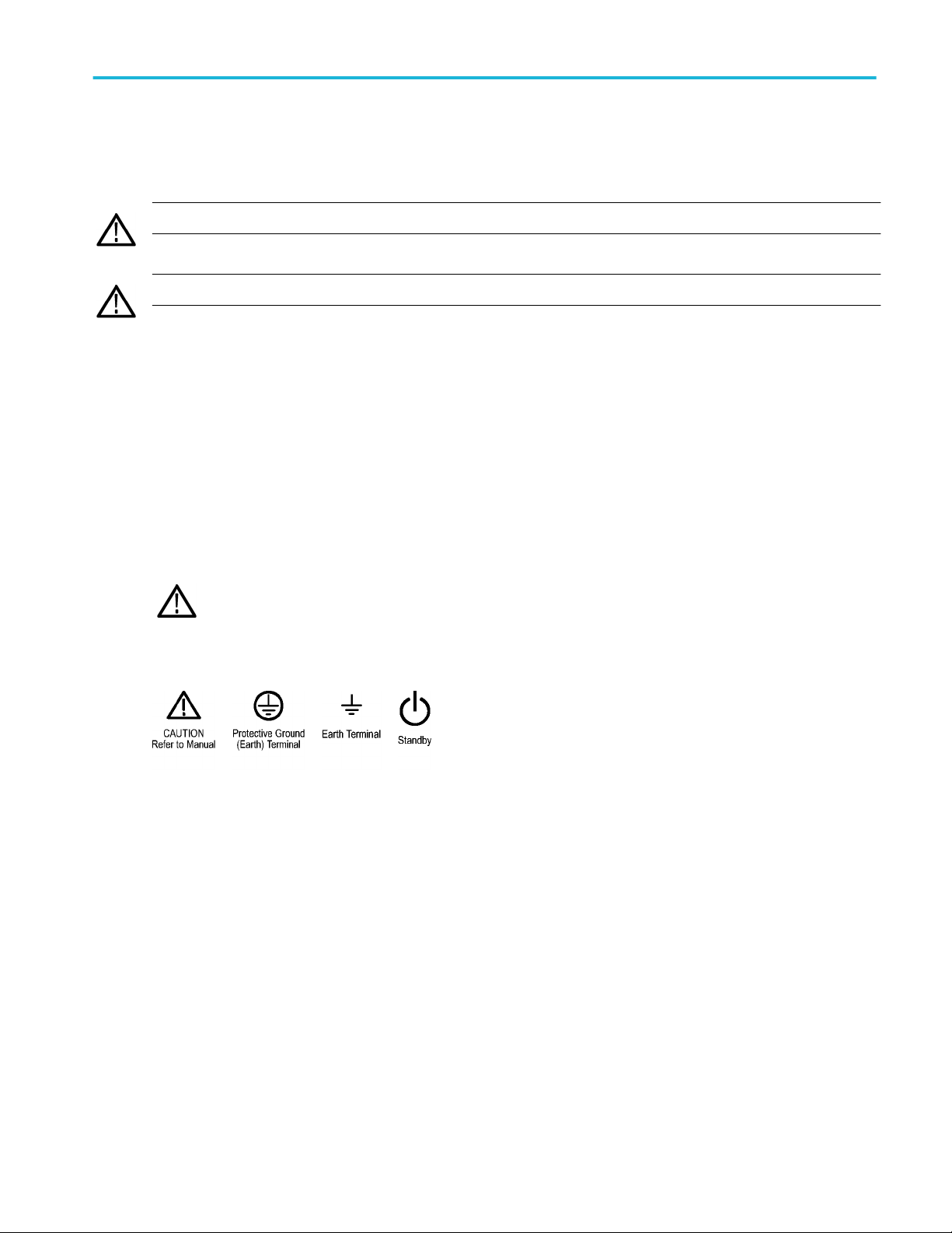
Symbols on the product
When this symbol is marked on the product, be sure to consult the manual to find out the nature of the potential
hazards and any actions which have to be taken to avoid them. (This symbol may also be used to refer the user to
ratings in the manual.)
The following symbols may appear on the product:
8 Series Installation and Safety Instructions v
Page 10

Important safety information
vi 8 Series Installation and Safety Instructions
Page 11

Compliance Information
This section lists the EMC (electromagnetic compliance), safety, and environmental standards with which the instrument
complies. This product is intended for use by professionals and trained personnel only; it is not designed for use in households or
by children.
Questions about the following compliance information may be directed to the following address:
Tektronix, Inc.
PO Box 500, MS 19-045
Beaverton, OR 97077, USA
www.tek.com
EMC compliance
EU EMC Directive
Meets intent of Directive 2014/30/EU for Electromagnetic Compatibility. Compliance was demonstrated to the following
specifications as listed in the Official Journal of the European Communities:
EN 61326-1, EN 61326-2-1. EMC requirements for electrical equipment for measurement, control, and laboratory use.
■
CISPR 11. Radiated and conducted emissions, Group 1, Class A
1 2 3
4
■
IEC 61000-4-2. Electrostatic discharge immunity
■
IEC 61000-4-3. RF electromagnetic field immunity
■
IEC 61000-4-4. Electrical fast transient / burst immunity
■
IEC 61000-4-5. Power line surge immunity
■
IEC 61000-4-6. Conducted RF immunity
■
IEC 61000-4-11. Voltage dips and interruptions immunity
6
5
EN 61000-3-2. AC power line harmonic emissions
EN 61000-3-3. Voltage changes, fluctuations, and flicker
1
This product is intended for use in nonresidential areas only. Use in residential areas may cause electromagnetic interference.
2
Emissions which exceed the levels required by this standard may occur when this equipment is connected to a test object.
3
Equipment may not meet the immunity requirements of applicable listed standards when test leads and/or test probes are connected due to coupling of electromagnetic
interference onto those leads/probes. To minimize the influence of electromagnetic interference, minimize the loop area between the unshielded portions of signal and
associated return leads, and keep leads as far away as possible from electromagnetic disturbance sources. Twisting unshielded test leads together is an effective way to
reduce loop area. For probes, keep the ground return lead as short as possible and close to the probe body. Some probes have accessory probe tip adapters to
accomplish this most effectively. In all cases, observe all safety instructions for the probes or leads used.
4
For compliance with the EMC standards listed here, high quality shielded interface cables that incorporate low impedance connection between the cable shield and the
connector shell should be used.
5
Up to 3.0 ps of additional jitter is allowed when the instrument is subjected to fields and signals as defined in the IEC 61000-4-3 tests.
6
Up to 3.0 ps of additional jitter is allowed when the instrument is subjected to fields and signals as defined in the IEC 61000-4-6 tests.
8 Series Installation and Safety Instructions vii
Page 12

Compliance Information
EMC Compliance
Meets the intent of Directive 2014/30/EU for Electromagnetic Compatibility when it is used with the product(s) stated in the
specifications table. Refer to the EMC specification published for the stated products. May not meet the intent of the directive if
used with other products.
Australia / New Zealand Declaration of Conformity – EMC
Complies with the EMC provision of the Radiocommunications Act per the following standard, in accordance with ACMA:
■
EN 61326-1 and EN 61326-2-1. Radiated and conducted emissions, Group 1, Class A.
Safety compliance
This section lists the safety standards with which the product complies and other safety compliance information.
EU declaration of conformity – low voltage
Compliance was demonstrated to the following specification as listed in the Official Journal of the European Union:
Low Voltage Directive 2014/35/EU.
■
EN 61010-1. Safety Requirements for Electrical Equipment for Measurement, Control, and Laboratory Use – Part 1: General
Requirements.
■
EN 61010-2-030. Safety Requirements for Electrical Equipment for Measurement, Control, and Laboratory Use – Part
2-030: Particular requirements for testing and measuring circuits.
U.S. nationally recognized testing laboratory listing
■
UL 61010-1. Safety Requirements for Electrical Equipment for Measurement, Control, and Laboratory Use – Part 1: General
Requirements.
■
UL 61010-2-030. Safety Requirements for Electrical Equipment for Measurement, Control, and Laboratory Use – Part
2-030: Particular requirements for testing and measuring circuits.
Canadian certification
■
CAN/CSA-C22.2 No. 61010-1. Safety Requirements for Electrical Equipment for Measurement, Control, and Laboratory Use
– Part 1: General Requirements.
■
CAN/CSA-C22.2 No. 61010-2-030. Safety Requirements for Electrical Equipment for Measurement, Control, and Laboratory
Use – Part 2-030: Particular requirements for testing and measuring circuits.
Additional compliances
■
IEC 61010-1. Safety Requirements for Electrical Equipment for Measurement, Control, and Laboratory Use – Part 1:
General Requirements.
■
IEC 61010-2-030. Safety Requirements for Electrical Equipment for Measurement, Control, and Laboratory Use – Part
2-030: Particular requirements for testing and measuring circuits.
Equipment type
Test and measuring equipment.
viii 8 Series Installation and Safety Instructions
Page 13

Compliance Information
Safety class
Class 1 – grounded product.
Pollution degree description
A measure of the contaminants that could occur in the environment around and within a product. Typically the internal
environment inside a product is considered to be the same as the external. Products should be used only in the environment for
which they are rated.
■
Pollution Degree 1. No pollution or only dry, nonconductive pollution occurs. Products in this category are generally
encapsulated, hermetically sealed, or located in clean rooms.
■
Pollution Degree 2. Normally only dry, nonconductive pollution occurs. Occasionally a temporary conductivity that is caused
by condensation must be expected. This location is a typical office/home environment. Temporary condensation occurs only
when the product is out of service.
■
Pollution Degree 3. Conductive pollution, or dry, nonconductive pollution that becomes conductive due to condensation.
These are sheltered locations where neither temperature nor humidity is controlled. The area is protected from direct
sunshine, rain, or direct wind.
■
Pollution Degree 4. Pollution that generates persistent conductivity through conductive dust, rain, or snow. Typical outdoor
locations.
Pollution degree rating
Pollution Degree 2 (as defined in IEC 61010-1). Note: Rated for indoor, dry location use only.
IP rating
IP20 (as defined in IEC 60529).
Measurement and overvoltage category descriptions
Measurement terminals on this product may be rated for measuring mains voltages from one or more of the following categories
(see specific ratings marked on the product and in the manual).
■
Measurement Category II. For measurements performed on circuits directly connected to the low-voltage installation.
■
Measurement Category III. For measurements performed in the building installation.
■
Measurement Category IV. For measurements performed at the source of low-voltage installation.
NOTE. Only mains power supply circuits have an overvoltage category rating. Only measurement circuits have a measurement
category rating. Other circuits within the product do not have either rating.
Mains overvoltage category rating
Overvoltage Category II (as defined in IEC 61010-1)
8 Series Installation and Safety Instructions ix
Page 14

Compliance Information
Environmental compliance
This section provides information about the environmental impact of the product.
Restriction of hazardous substances
Complies with RoHS2 Directive 2011/65/EU.
Product end-of-life handling
Observe the following guidelines when recycling an instrument or component:
Equipment recycling. Production of this equipment required the extraction and use of natural resources. The equipment may
contain substances that could be harmful to the environment or human health if improperly handled at the product’s end of life.
To avoid release of such substances into the environment and to reduce the use of natural resources, we encourage you to
recycle this product in an appropriate system that will ensure that most of the materials are reused or recycled appropriately.
This symbol indicates that this product complies with the applicable European Union requirements according to
Directives 2012/19/EU and 2006/66/EC on waste electrical and electronic equipment (WEEE) and batteries. For
information about recycling options, check the Tektronix Web site (www.tek.com/productrecycling).
x 8 Series Installation and Safety Instructions
Page 15

Preface
TSO8 Series
The 8 Series is a disaggregated platform that provides you with a scalable, reconfigurable sampling oscilloscope. The 8 Series
consists of:
■
TSO820: Sampling oscilloscope mainframe that can house up to two modules.
■
TSOVu: Software application you install on a PC. It provides the UI for the oscilloscope (connects to the mainframe through
LAN).
■
TSO8C17, TSO8C18: Optical modules (you can select one or more). The TSO8C17 is a one channel module, the
TSO8C18 is a two channel module.
The TSO820 is an equivalent time sampling oscilloscope suitable for use in a variety of test and measurement applications and
systems. The mainframe must be configured with at least one modular sampling module plug-in.
This document describes the installation, setup, and basic operating information of the Tektronix TSO8 Series Sampling
Oscilloscope, TSOVu™ analysis software, and related modules. The TSO 8 Series supports optical device characterization at
56 GBd and 28 GBd on a disaggregated platform with LAN interface and analysis software that runs on a PC.
Key features include
Key performance specifications
■
Low time base jitter
■
Optical bandwidth above 30 GHz
■
Single mode and multi-mode support for short and long wavelength optical testing
■
Optical Reference Receiver (ORR) support for standard-mandated compliance testing
New system architecture
■
Disaggregated architecture separates acquisition hardware and software analysis, allowing data to be streamed over
Ethernet to any connected PC running TSOVu™ . Scale your analysis platforms to fit your needs and connect from
anywhere on the network.
■
Swap modules for various configuration.
Optical modules
■
Accurate testing and characterization of short or long wave optical signals using the high sensitivity and low noise
performance of the TSO8C17 or TSO8C18 modules.
■
Optical Reference Receivers (ORR) to support specified requirements for standards mandated compliance testing.
■
Calibrated extinction ratio measurements and variable correction ER measurements to ensure accuracy and repeatability.
8 Series Installation and Safety Instructions
1
Page 16

Preface
Analysis with TSOVu
■
The TSOVu™ software platform runs independent of the oscilloscope mainframe on your PC to support both live and postprocessing of acquired data.
■
Offers comprehensive analysis of PAM4 optical signals. Includes support for eye diagrams, optical measurements such as
TDECQ, and other standard measurements. Measurements like PAM2 / NRZ are also available.
™
High test throughput
■
High sample acquisition rate at 300 kS/s per channel standard
■
Sophisticated Programmatic Interface (PI) for automation environments to enable the highest test throughput. Each
command supports full data synchronization, eliminating the need to wait / sleep statements.
Available product documentation
The following documents for the TSO8 Series are available for download. For the most recent versions these documents, visit
the Tektronix Web site at www.tek.com. You can find manuals by searching on the product name and selecting the Manuals
filter.
To learn about Use this document
How to install and turn on the
instrument software and
hardware; read safety and
compliance information
How to operate the instrument,
take measurements, and
navigate the UI.
How to remotely control the
instrument using GPIB
programmatic commands.
Syntax provided.
Mainframe and module
specifications. Includes
procedures to verify that the
mainframe and modules meet
warranted specifications.
Installing up to two
mainframes, or one mainframe
and one TCR801 clock
recovery unit, into a standard
instrument rack using the
rackmount kit.
How to declassify, sanitize,
and clear memory devices in
the instrument.
TSO8 Series Installation and Safety Instructions
Printed and shipped with the instrument. Also available online as a downloadable PDF. This
document contains content in English, Japanese, and Simplified Chinese.
TSO8 Series Help
Available in the TSOVu application (Help menu) and as a downloadable PDF at www.tek.com.
TSO8 Series Programming Manual
TSO8 Series Specifications and Performance Verification Technical Reference
8 Series Rackmount Kit Instructions
TSO8 Series Declassification and Security Instructions
2 8 Series Installation and Safety Instructions
Page 17

Introduction to the instrument
What ships with your product
Standard accessories
Item Tektronix part number or nomenclature
Sampling oscilloscope mainframe (if ordered) TSO820
1 channel 28 GBd / 53 GBd optical module (if ordered) TSO8C17
2 channel 28 GBd / 53 GBd optical module (if ordered) TSO8C18
Power cord Appropriate for your country
Ethernet CAT6 cable 174-7292-xx
ESD wrist strap 006-3415-xx
Front cover for instrument mainframe (if mainframe was
ordered)
One empty module slot filler (filler module) (if mainframe
was ordered)
Printed Safety and Installation manual (this manual) 071-3663-xx
200-5473-xx
407-6185-xx
Recommended accessories
Item Tektronix part number or nomenclature
1 channel 28 GBd / 53 GBd optical module TSO8C17
2 channel 28 GBd / 53 GBd optical module TSO8C18
Rackmount kit 644-1095-xx
Hard transit case 016-2161-00
TSO820 D1 Calibration data report N/A
Environmental requirements
Characteristic Description
Operating temperature 5 °C to +45 °C (+41 °F to +113 °F)
Operating humidity 5% to 95% relative humidity (% RH) at up to +30 °C (+86 °F),
Operating altitude Up to 3000 meters (9842 feet)
Clearance requirements Rear: 5.08 cm (2 in)
noncondensing.
5% to 45% relative humidity (% RH) above +30 °C (+86 °F) up
to +45 °C (113 °F), noncondensing.
Sides: 5.08 cm (2 in)
Bottom: Cooling inlets on the bottom require that the instrument
rests on a flat surface with the feet providing sufficient
clearance.
8 Series Installation and Safety Instructions 3
Page 18

Introduction to the instrument
Power requirements
Characteristic Description
Input voltage 100 V - 240 V, 115 V
Frequency 50/60 Hz, 400 Hz
Power consumption 200 W (maximum)
WARNING: To reduce the risk of fire and shock, ensure that the mains power supply voltage fluctuations do not exceed 10% of
the operating voltage range.
Electrostatic discharge information
Read the electrostatic discharge (ESD) Read This First document that shipped with the mainframe and module for complete
information about how to prevent damage to the modules and mainframe due to ESD. Following is some of that information.
CAUTION. To prevent damage to the instrument and electrical modules from electrostatic discharge (ESD), install 50 Ω
terminations on the module connectors before removing them from the mainframe or when it is not in use.
CAUTION. Store modules in static-free containers. Whenever you move a module from one instrument to another, use a staticfree container in which to transport it. This will help prevent damage due to ESD.
CAUTION. To prevent damage to the electrical module, discharge to ground any electrostatic charge that may be present on the
center and outer conductors of cables before attaching a cable to a module.
CAUTION.
To prevent damage to the modules, always wear a grounded antistatic strap (provided with the instrument) when handling
modules or making connections. Wear anti-static clothing and work at a static-free workstation when using the modules.
4 8 Series Installation and Safety Instructions
Page 19

Introduction to the instrument
Front panel
The front panel of your instrument gives you access to the following.
Number Item Description
1 Power button Turn on/off power to instrument and
installed modules. Blue indicates power is
on. Amber indicates standby power is on.
2 LCD display Shows MAC and IP addresses. Navigate
using scroll/select buttons. 61 mm (W) x
12 mm (H) x 2x20 liquid crystal display
(LCD).
3 Slot 1 Slot for module.
4 Slot 2 Slot for module.
5 Keypad buttons Scroll/select buttons to navigate LCD
display.
6 Clock Prescale Input 2.92 mm. 50 Ω, AC-coupled, divide-by-
one/two/four/eight external trigger input
port, enabling direct or prescaled
triggering for clocks in the frequency
range of 500MHz - 32 GHz.
7 Antistatic connection 1MΩ A banana-jack antistatic connection of
1 MΩ to ground.
8 Series Installation and Safety Instructions 5
Page 20

Introduction to the instrument
Rear panel
The rear panel of your instrument gives you access to the following.
Number Item Description
1 Security cable slot Security cable can be attached to secure
instrument to a physical location.
2 Module vents Provides airflow for installed modules.
There is one fan in each module slot.
3 USB port USB 3.0
4 Mfg port Not for use.
5 LAN port 10/100/1000 Gb Ethernet
6 Side feet The side feet (4) protect the product when
placed on its side. Do not use this
equipment while turned on if the
instrument is sitting on its side feet.
7 Power Input voltage: 100 - 240 V, 115 V
Frequency: 50 - 60 Hz, 400 Hz
Power: 200 W max
8 Rear feet The rear feet (4) are for preventing
damage of connected cables or power
cord if those are connected and the
instrument is placed on its rear. Do not
use this equipment while turned on if the
instrument is sitting on its rear feet.
9 Handle Carrying handle.
WARNING. Do not use this equipment while turned on if the instrument is sitting on its rear feet. This can prevent proper air flow.
6 8 Series Installation and Safety Instructions
Page 21

Initial setup and connection
Module installation and removal
Procedure for installing and removing modules.
The TSO820 sampling oscilloscope allows for installation of the following two modules. For detailed specifications information,
see the TSO820, TSO8C17, TSO8C18 Sampling Oscilloscope and Modules Specifications and Performance Verification manual
available for download on www.tek.com.
■
TSO8C17, 1 channel 28 GBd / 53 GBd
■
TSO8C18, 2 channel 28 GBd / 53 GBd
CAUTION. Only qualified personnel should perform the following procedures. Ensure power is off to the unit before installing or
removing modules.
CAUTION. To prevent damage to the modules, wear a grounded antistatic strap when removing and installing modules and
cables connected to modules.
Install a module
CAUTION. Do not hot swap modules. Installing or removing modules into/from the mainframe with the power on will damage the
module. To avoid damage, turn off the power before installing or removing a module.
1. Power off the mainframe.
2. Use a flathead screw driver to loosen the two latch screws that secure the top cover to the mainframe and lift off the cover.
8 Series Installation and Safety Instructions 7
Page 22

Initial setup and connection
3. Notice that the mainframe ships with one filler module installed. This is a place holder that ensures proper air flow and
temperature stability when only one module is installed.
Before installing a module, remove the filler module from the side into which you want to insert the regular module by
loosening the securing screws (they are captive and stay attached to the filler module).
Never leave a module slot empty while the instrument is powered on and running. Always have a filler or regular modules
installed to ensure proper air flow and temperature stability.
4. Insert the desired module into the mainframe at an angle, as shown.
5. Push down lightly on the rear of the module to seat it securely into the mainframe. You will hear a click when it seats fully.
6. Tighten the 4 attached screws to secure the module to the mainframe.
7. Replace the mainframe cover and use the driver again to turn the screw latches to secure it in place.
8. Before taking measurements, allow a minimum 30 minutes warmup and run a compensation.
8 8 Series Installation and Safety Instructions
Page 23

Initial setup and connection
Remove a module
CAUTION. Do not hot swap modules. Installing or removing modules into/from the mainframe with the power on will damage the
module. To avoid damage, turn off the power before installing or removing a module.
1. Power off the mainframe.
2. Use a flathead screw driver to loosen the two latch screws that secure the top cover to the mainframe and lift off the cover.
3. Loosen the 4 screws that secure the module to the mainframe. These are captive screws and stay attached to the module.
4. Grasp the rear of the module (as noted on the module) and pull up at an angle to unseat the module.
5. Lift the module from the mainframe at an angle to remove it.
6. Before powering on the mainframe, ensure a filler module or module is installed in the side from which you removed the
module.
The mainframe ships with one filler module installed. This is a place holder that ensures proper air flow and temperature
stability when only one or module is installed.
Never leave a module slot empty while the instrument is powered on and running. Always have a filler or regular modules
installed to ensure proper air flow and temperature stability.
7. Replace the mainframe cover and turn the screw latches to secure it in place.
8. Before taking measurements, allow a minimum 30 minutes warmup and run a compensation.
Software installation and requirements
The following software is available for the 8 Series. The TSOVu base software enables mainframe connectivity and operation,
cursors, results tables, and other features. The base software package also includes the Pulse measurements plug-in. Other
plug-ins are available for purchase and download separately.
PC system requirements
Install the software on a PC with the following specifications.
Item Requirement
Operating system Microsoft® Windows 10, 64 Bit
CPU Recommended: AMD Ryzen 7 or Intel i7 class CPU with
Memory 16 Gbytes (recommended)
Disk 256 GBytes SSD or more
Networking 1 Gigabit Ethernet wired
4 core / 8 thread
Minimum: AMD Ryzen 5 or Intel i5 with hyperthreading
Note that the time to calculate the TDECQ result is inversely
proportionate to the clock speed.
8 Series Installation and Safety Instructions 9
Page 24

Initial setup and connection
Other software requirements
You must install MATLAB® Compiler Runtime version 9.3 on to the host PC. Go to MathWorks (https://www.mathworks.com/
products/compiler/matlab-runtime.html) to download and install it.
Install TSOVu software
You must install the base software before installing any plug-ins. The downloadable package will include the base software and
the Pulse and PAM4 measurement plug-ins. The PAM4 plug-in is optional and requires a purchased license to enable it. Install
the software as follows.
1. Go to www.tek.com and click the Download icon.
2. Select Software, enter TSOVu, and click Search.
3. Find the most recent version of the TSOVu base software and download the package to the PC you will use to connect with
and control the mainframe.
4. Double click the .exe file to launch the install wizard. Follow the instructions to install the software. Your PC with
automatically restart when the installation is complete.
5. A TSOVu icon will install on the Windows Desktop. Click to launch the application.
The following items are installed with the base software package:
TSOVu
™
■
The application that runs on your PC and is the analysis engine and UI of the mainframe and modules. It is required to
connect to a mainframe.
■
Pulse measurement plug-in
This plug-in comes standard with the base installation package and provides pulse measurement capabilities.
■
PAM4 measurement plug-in
Use of this plug-in is optional. To enable it, you must purchase a license.
10 8 Series Installation and Safety Instructions
Page 25

Initial setup and connection
■
TSO8 firmware
■
TekVISA
A library of industry-standard compliant software components, organized according to the standard VISA model established
by the VXIplug&play Systems Alliance. Use TekVISA software to write interoperable instrument drivers to handle
communicating between software applications and your instrument.
™
Install optional plug-ins
For a full list of optional plug-ins, see the Software licenses and options topic in the Help or view the TSO 8 Series product
datasheet on www.tek.com. Due to the plug-in architecture of TSOVu, measurement plug-ins must be installed prior to TSOVu
software launch. To purchase and download optional plug-ins, do the following.
1. Navigate to your TekAMS system account and purchase the desired plug-in(s).
2. Run the plug-in installer with administrative privileges and walk through the installation procedure for each measurement
plug-in.
3. Re-launch TSOVu.
4. Install the new plug-in license(s) from Help > About in the TSOVu application.
(See the Software licenses and options topic next for more information.)
See these TSOVu Help topics for more information:
Software licenses and options
Connect to network and TSOVu
Firmware installation and requirements
Run signal path compensation (SPC)
Software licenses and options
The TSOVu application is made up of the base software, Pulse measurement plug-in, and any additionally purchased plug-in
software (licensed optional software). The base package enables mainframe connectivity and operation, cursors, results tables,
pulse measurements, and other baseline features. It is free and available for download at www.tek.com\downloads.
To install a license in TSOVu
1. Select Help > About from the TSOVu main menu bar to view installed options and system information.
2. Click the Install License button under the Installed Options table.
3. Select the appropriate install location:
a. TSOVu: The license will install on the PC. Anyone using that PC will have access to the license for any instruments to
which it connects.
b. Instrument: The license will install on the selected instrument. Any PC connecting to that instrument will have access to
license.
4. Click the Browse button to open a file explorer window and navigate to the location to which you saved the license file from
the Tek AMS system.
5. Click Open.
6. Click the Install button.
8 Series Installation and Safety Instructions 11
Page 26

Initial setup and connection
To copy system information (TSOVu SW version, host ID, plug-in versions)
1. Select Help > About from the TSOVu main menu bar to view installed options and system information.
2. Click the Copy System Information button under the System Information table.
3. The information from the table has been copied to a clipboard. You can now paste it into a document of your choice.
Plug-in options
The following optional plug-ins are available to add to the TSOVu base software. These plug-ins enable new capabilities. For the
most updated list of options, please view the TSO 8 Series datasheet at www.tek.com.
Plug-in description Option License
Measurements for PAM4 optical signals.
Enables TDECQ equalization and
analysis.
TSO8SW-NLP-PAM4-O License; PAM4 Optical Measurements;
Node-Locked Perpetual
TSO8SW-FLP-PAM4-O License; PAM4 Optical Measurements;
Floating Perpetual
TSO8SW-NL1-PAM4-O License; PAM4 Optical Measurements;
Node-Locked 1-Year subscription
TSO8SW-NL3-PAM4-O License; PAM4 Optical Measurements;
Node-Locked 3-Year subscription
TSO8SW-FL1-PAM4-O License; PAM4 Optical Measurements;
Floating 1-Year subscription
TSO8SW-FL3-PAM4-O License; PAM4 Optical Measurements;
Floating 3-Year subscription
License options
License types
■
Perpetual: This license does not expire, but updates and support are available for a set time period. Support can be
renewed for an annual fee. When that annual subscription of the perpetual license expires, the software will be usable but
frozen to the last released version before the expiration date.
■
Subscription: This license provides use, updates, and support of the software throughout the term of the license. When the
license expires, those software features will no longer work.
License terms
■
Node-locked: License assigned to a specific instrument/PC. It cannot be transferred to any other instrument/PC.
■
Floating: License can be transferred from one instrument/PC to another. It can only be used on one instrument/PC at a
time.
See these topics for more information:
Software installation and requirements
Connect to network and TSOVu
Available product documentation
12 8 Series Installation and Safety Instructions
Page 27

Initial setup and connection
Firmware installation and requirements
Keep the mainframe firmware updated to ensure the latest features are available and the instrument is taking the most accurate
measurements. You can do this by downloading the latest firmware from www.tek.com and installing it yourself. Module firmware
can only be updated by the Tektronix service organization.
Determine the current version of firmware installed on the instrument using the front panel LCD screen menu.
1. Download the instrument firmware to a USB drive:
a. Navigate to C:\Program Files\Tektronix\TSOVu_Firmware to locate the firmware that was downloaded to your PC when
you installed the TSOVu installation package.
b. If the available firmware version is newer than what is on your instrument, select that file.
c. Copy the .img file to a USB memory device.
2. Install firmware on instrument:
a. Power on the instrument and wait for the instrument to fully boot up.
b. Insert the USB flash drive into the USB port on the instrument rear panel.
c. Cycle the power on the mainframe to begin the update process. The process status will appear on the front panel LCD
until finished.
d. The instrument will update the firmware and power on immediately following installation completion.
e. Remove the USB stick after the instrument has powered on successfully.
NOTE. Do not power off the instrument or remove the USB flash drive until the instrument finishes installing the firmware.
Remove the USB drive before powering on the instrument.
3. Confirm that the firmware was updated:
a. Check the Firmware version in the Firmware menu on the front panel LCD. It should now show the updated version.
If an error occurs, try to reformat your USB drive. Navigate to Computer Management > Disk Management on your PC to
repartition the USB drive with the default allocation unit size.
Connect the mainframe to the network and TSOVu
To control the instrument with the TSOVu application, the instrument must be made available to the same LAN as the PC hosting
TSOVu. The oscilloscope has a standard Ethernet (RJ-45) interface for connecting to a network.
Use the included CAT6 Ethernet cable. If you use a different type of Ethernet cable, it must be a CAT6 or faster cable and it
should be consistent with the network speed you require.
8 Series Installation and Safety Instructions 13
Page 28

Initial setup and connection
1. Connect the CAT6 Ethernet cable to the LAN connector on the rear panel of the instrument.
2. Plug in the instrument power cord to the instrument and then a power source. The instrument will power on automatically.
3. Press the right/left arrow keys on the mainframe front panel until you see IP address on the LCD display. Note the IP
address. Only DHCP addresses are supported.
4. Launch TSOVu.
5. In TSOVu, select Connect > System Configuration and enter the previously noted IP address.
6. Press the green + button (or the Enter key on a keyboard) and the instrument will connect. Mainframe and modules names
and firmware versions will appear.
14 8 Series Installation and Safety Instructions
Page 29

Initial setup and connection
Next steps:
See the Run signal path compensation (SPC) topic in the Help for instructions for running a SPC before connecting a signal to
view.
8 Series Installation and Safety Instructions 15
Page 30

Initial setup and connection
16 8 Series Installation and Safety Instructions
Page 31

Cleaning
Cleaning the instrument
Periodically you may need to clean the exterior of your instrument. To do so, follow the instructions in this section.
Warning. Before performing any procedure that follows, power down the instrument and disconnect it from line voltage.
Exterior cleaning
CAUTION.
To prevent getting moisture inside the instrument during external cleaning, use only enough liquid to dampen the cloth or
applicator.
Clean the exterior surfaces of the chassis with a dry lint-free cloth or a soft-bristle brush. If any dirt remains, use a cloth or swab
dipped in a 70% isopropyl alcohol solution. Use a swab to clean narrow spaces around controls and connectors. Do not use
abrasive compounds on any part of the chassis, as they may damage it.
CAUTION.
Avoid the use of chemical cleaning agents, which might damage the plastics used in this instrument. Use a 70% isopropyl alcohol
solution as a cleaner and wipe with a clean cloth dampened with deionized water. (Use only deionized water when cleaning the
menu buttons or front-panel buttons.) Before using any other type of cleaner, consult your Tektronix Service Center or
representative.
Optical connector cleaning
Keep the optical module connectors clean to maintain measurement accuracy. The optical module user manual contains the
procedures for cleaning optical connectors.
8 Series Installation and Safety Instructions 17
Page 32

Cleaning
18 8 Series Installation and Safety Instructions
Page 33

Index
A
Accessories, 3
C
Cleaning, 17
Connectivity
TekVISA, 9
D
M
Manuals, 2
MATLAB, 9
Measurements
PAM4, 9
Pulse, 9
Module installation, 7, 9
Module removal, 7, 9
Documentation, 2
E
Environmental requirements, 3
F
firmware, how to update, 13
H
how to
download, install firmware, 13
update firmware, 13
I
Installation, 9
Installation of modules, 7, 9
O
Options, 11
P
PAM4, 9
Plug-in, 11
Power requirements, 4
Pulse, 9
S
Software, 9
Software licenses, 11
Software version, 11
Support, 2
System information, 11
T
L
Licenses, 11
8 Series Installation and Safety Instructions 19
TekVISA, 9
TSOVu, 9
Page 34

Index
20 8 Series Installation and Safety Instructions
 Loading...