

Page 1

Service Manual
TSG 95
PAL/NTSC Signal Generator
070-8917-04
Warning
The servicing instructions are for use by qualified
personnel only. To avoid personal injury, do not
perform any servicing unless you are qualified to
do so. Refer to all safety summaries prior to
performing service.
www.tektronix.com
Page 2

Copyright © T ektronix, Inc. All rights reserved. T ektronix products are covered by U.S. and foreign patents, issued and pending. Information in this publication supercedes
that in all previously published material. Specifications and price change privileges reserved.
Printed in the U.S.A.
T ektronix, Inc., P.O. Box 1000, Wilsonville, OR 97070–1000
TEKTRONIX and TEK are registered trademarks of T ektronix, Inc.
Page 3

WARRANTY
T ektronix warrants that the products that it manufactures and sells will be free from defects in materials and workmanship
for a period of one (1) year from the date of shipment. If a product proves defective during this warranty period, T ektronix,
at its option, either will repair the defective product without charge for parts and labor, or will provide a replacement in
exchange for the defective product.
In order to obtain service under this warranty, Customer must notify Tektronix of the defect before the expiration of the
warranty period and make suitable arrangements for the performance of service. Customer shall be responsible for
packaging and shipping the defective product to the service center designated by T ektronix, with shipping charges prepaid.
T ektronix shall pay for the return of the product to Customer if the shipment is to a location within the country in which the
T ektronix service center is located. Customer shall be responsible for paying all shipping charges, duties, taxes, and any
other charges for products returned to any other locations.
This warranty shall not apply to any defect, failure or damage caused by improper use or improper or inadequate
maintenance and care. T ektronix shall not be obligated to furnish service under this warranty a) to repair damage resulting
from attempts by personnel other than T ektronix representatives to install, repair or service the product; b) to repair
damage resulting from improper use or connection to incompatible equipment; c) to repair any damage or malfunction
caused by the use of non-T ektronix supplies; or d) to service a product that has been modified or integrated with other
products when the effect of such modification or integration increases the time or difficulty of servicing the product.
THIS WARRANTY IS GIVEN BY TEKTRONIX IN LIEU OF ANY OTHER WARRANTIES, EXPRESS OR
IMPLIED. TEKTRONIX AND ITS VENDORS DISCLAIM ANY IMPLIED WARRANTIES OF
MERCHANTABILITY OR FITNESS FOR A PAR TICULAR PURPOSE. TEKTRONIX’ RESPONSIBILITY TO
REP AIR OR REPLACE DEFECTIVE PRODUCTS IS THE SOLE AND EXCLUSIVE REMEDY PROVIDED TO
THE CUSTOMER FOR BREACH OF THIS WARRANTY. TEKTRONIX AND ITS VENDORS WILL NOT BE
LIABLE FOR ANY INDIRECT , SPECIAL, INCIDENTAL, OR CONSEQUENTIAL DAMAGES IRRESPECTIVE
OF WHETHER TEKTRONIX OR THE VENDOR HAS ADVANCE NOTICE OF THE POSSIBILITY OF SUCH
DAMAGES.
Page 4

Page 5

DECLARATION OF CONFORMITY
We
Tektronix, Inc.
Television Products Division
P.O. Box 500
Beaverton, Oregon U.S.A.
declare under our sole responsibility that the
TSG95 PAL/NTSC Signal Generator
to which this declaration relates is in conformity with the following standards:
EN50081-1, Generic Emission Standard
EN50082-1, Generic Immunity Standard
EN60555-2, Power Line Harmonics Standard
following the provisions of the Directive(s) of the Council of the European Union:
EMC Directive 89/366/EEC.
Original Declaration Of Conformity is on file with:
Tektronix Holland N.V.
Marktweg 73A
8444 AB Heerenveen
The Netherlands
TSG 95 Service Manual
Page 6

TSG 95 Service Manual
Page 7

Table of Contents
List of Figures ii. . . . . . . . . . . . . . . . . . . . . . . . . . . . . . . . . . . . . . . . . . . . .
List of Tables iii. . . . . . . . . . . . . . . . . . . . . . . . . . . . . . . . . . . . . . . . . . . . . .
General Safety Summary v. . . . . . . . . . . . . . . . . . . . . . . . . . . . . . . . . . .
Service Safety Summary vii. . . . . . . . . . . . . . . . . . . . . . . . . . . . . . . . . . . .
Specifications 1–1. . . . . . . . . . . . . . . . . . . . . . . . . . . . . . . . . . . . . . . . . . . . .
Operating Information 2–1. . . . . . . . . . . . . . . . . . . . . . . . . . . . . . . . . . . . .
Introduction 1–1. . . . . . . . . . . . . . . . . . . . . . . . . . . . . . . . . . . . . . . . . . . .
Reference Documentation 1–1. . . . . . . . . . . . . . . . . . . . . . . . . . . . . . . . .
Performance Conditions 1–2. . . . . . . . . . . . . . . . . . . . . . . . . . . . . . . . . .
Safety Standard Compliance 1–2. . . . . . . . . . . . . . . . . . . . . . . . . . . . . . .
EMI Compliance 1–2. . . . . . . . . . . . . . . . . . . . . . . . . . . . . . . . . . . . . . . .
Specification Tables 1–3. . . . . . . . . . . . . . . . . . . . . . . . . . . . . . . . . . . . . .
PAL Waveform Diagrams 1–14. . . . . . . . . . . . . . . . . . . . . . . . . . . . . . . . .
NTSC Waveform Diagrams 1–28. . . . . . . . . . . . . . . . . . . . . . . . . . . . . . .
Getting Started 2–1. . . . . . . . . . . . . . . . . . . . . . . . . . . . . . . . . . . . . . . . . .
Supplying Power 2–2. . . . . . . . . . . . . . . . . . . . . . . . . . . . . . . . . . . . . . . .
Connecting the TSG 95 2–4. . . . . . . . . . . . . . . . . . . . . . . . . . . . . . . . . . .
Keypad and Display Conventions 2–4. . . . . . . . . . . . . . . . . . . . . . . . . . .
Definitions 2–5. . . . . . . . . . . . . . . . . . . . . . . . . . . . . . . . . . . . . . . . . . . . .
Preliminary Settings 2–5. . . . . . . . . . . . . . . . . . . . . . . . . . . . . . . . . . . . .
Other Settings 2–6. . . . . . . . . . . . . . . . . . . . . . . . . . . . . . . . . . . . . . . . . .
Using Your TSG 95 2–7. . . . . . . . . . . . . . . . . . . . . . . . . . . . . . . . . . . . . .
Theory of Operation 3–1. . . . . . . . . . . . . . . . . . . . . . . . . . . . . . . . . . . . . . .
Circuit Description 3–1. . . . . . . . . . . . . . . . . . . . . . . . . . . . . . . . . . . . . .
Performance Verification and Adjustment Procedures 4–1. . . . . . . . . . .
Required Test Equipment 4–1. . . . . . . . . . . . . . . . . . . . . . . . . . . . . . . . .
Performance Verification Checklist 4–3. . . . . . . . . . . . . . . . . . . . . . . . . .
Performance Verification Procedures 4–4. . . . . . . . . . . . . . . . . . . . . . . .
Adjustment Checklist 4–22. . . . . . . . . . . . . . . . . . . . . . . . . . . . . . . . . . . .
Adjustment Procedures 4–24. . . . . . . . . . . . . . . . . . . . . . . . . . . . . . . . . . .
Maintenance 5–1. . . . . . . . . . . . . . . . . . . . . . . . . . . . . . . . . . . . . . . . . . . . . .
Battery Hints 5–1. . . . . . . . . . . . . . . . . . . . . . . . . . . . . . . . . . . . . . . . . . .
Preventive Maintenance 5–2. . . . . . . . . . . . . . . . . . . . . . . . . . . . . . . . . .
Troubleshooting Aids 5–3. . . . . . . . . . . . . . . . . . . . . . . . . . . . . . . . . . . .
The Utility Menu 5–4. . . . . . . . . . . . . . . . . . . . . . . . . . . . . . . . . . . . . . . .
Corrective Maintenance 5–11. . . . . . . . . . . . . . . . . . . . . . . . . . . . . . . . . . .
Replacing Assemblies 5–12. . . . . . . . . . . . . . . . . . . . . . . . . . . . . . . . . . . .
Replaceable Electrical Parts 6–1. . . . . . . . . . . . . . . . . . . . . . . . . . . . . . . . .
Parts Ordering Information 6–1. . . . . . . . . . . . . . . . . . . . . . . . . . . . . . . .
Using the Replaceable Electrical Parts List 6–1. . . . . . . . . . . . . . . . . . .
Column Descriptions 6–2. . . . . . . . . . . . . . . . . . . . . . . . . . . . . . . . . . . . .
Cross Index – Mfr. Code Number To Manufacturer 6–3. . . . . . . . . . . . .
TSG 95 Service Manual
i
Page 8

Table of Contents
List of Figures
Replaceable Electrical Parts 6–4. . . . . . . . . . . . . . . . . . . . . . . . . . . . . . .
Diagrams and Circuit Board Illustrations 7–1. . . . . . . . . . . . . . . . . . . . . .
Replaceable Mechanical Parts 8–1. . . . . . . . . . . . . . . . . . . . . . . . . . . . . . .
Parts Ordering Information 8–1. . . . . . . . . . . . . . . . . . . . . . . . . . . . . . . .
Using the Replaceable Mechanical Parts List 8–1. . . . . . . . . . . . . . . . . .
Column Descriptions 8–2. . . . . . . . . . . . . . . . . . . . . . . . . . . . . . . . . . . . .
Cross Index – Mfr. Code Number To Manufacturer 8–3. . . . . . . . . . . . .
Replaceable Mechanical Parts 8–3. . . . . . . . . . . . . . . . . . . . . . . . . . . . . .
Figure 1–1: PAL 75% Color Bars 1–14. . . . . . . . . . . . . . . . . . . . . . . . . . . . .
Figure 1–2: PAL 100% Color Bars 1–14. . . . . . . . . . . . . . . . . . . . . . . . . . . .
Figure 1–3: PAL 75% Red and Red Field 1–15. . . . . . . . . . . . . . . . . . . . . . .
Figure 1–4: PAL 100% Red 1–15. . . . . . . . . . . . . . . . . . . . . . . . . . . . . . . . . .
Figure 1–5: PAL Green Field 1–16. . . . . . . . . . . . . . . . . . . . . . . . . . . . . . . .
Figure 1–6: PAL Blue Field 1–16. . . . . . . . . . . . . . . . . . . . . . . . . . . . . . . . . .
Figure 1–7: PAL 50% Flat Field 1–17. . . . . . . . . . . . . . . . . . . . . . . . . . . . . .
Figure 1–8: PAL 100% Flat Field 1–17. . . . . . . . . . . . . . . . . . . . . . . . . . . . .
Figure 1–9: PAL 0% Flat Field 1–18. . . . . . . . . . . . . . . . . . . . . . . . . . . . . . .
Figure 1–10: PAL Convergence (vertical lines) 1–18. . . . . . . . . . . . . . . . . . .
Figure 1–11: PAL Convergence (horizontal lines) 1–19. . . . . . . . . . . . . . . . .
Figure 1–12: PAL 5 Step (Gray Scale) 1–19. . . . . . . . . . . . . . . . . . . . . . . . . .
Figure 1–13: PAL Modulated 5 Step 1–20. . . . . . . . . . . . . . . . . . . . . . . . . . . .
Figure 1–14: PAL Multiburst 1–20. . . . . . . . . . . . . . . . . . . . . . . . . . . . . . . . . .
Figure 1–15: PAL Reduced Sweep 1–21. . . . . . . . . . . . . . . . . . . . . . . . . . . . .
Figure 1–16: PAL Pluge 1–21. . . . . . . . . . . . . . . . . . . . . . . . . . . . . . . . . . . . .
Figure 1–17: PAL Matrix Signal — CCIR 17 1–22. . . . . . . . . . . . . . . . . . . . .
Figure 1–18: PAL Matrix Signal — CCIR Line 330 1–22. . . . . . . . . . . . . . . .
Figure 1–19: PAL Matrix Signal — CCIR Line 331 1–23. . . . . . . . . . . . . . . .
Figure 1–20: PAL Matrix Signal — CCIR 18 1–23. . . . . . . . . . . . . . . . . . . . .
Figure 1–21: PAL Matrix Signal — (Sin x)/x 1–24. . . . . . . . . . . . . . . . . . . . .
Figure 1–22: PAL Matrix Signal — 15 kHz Square Wave 1–24. . . . . . . . . . .
Figure 1–23: PAL Matrix Signal — Shallow Ramp 1–25. . . . . . . . . . . . . . . .
Figure 1–24: PAL Matrix Signal — UK ITS 1 1–25. . . . . . . . . . . . . . . . . . . .
Figure 1–25: PAL Matrix Signal — UK ITS 2 1–26. . . . . . . . . . . . . . . . . . . .
Figure 1–26: PAL Safe Area 1–27. . . . . . . . . . . . . . . . . . . . . . . . . . . . . . . . . .
Figure 1–27: SMPTE (NTSC) Color Bar Components 1–28. . . . . . . . . . . . . .
Figure 1–28: SMPTE (NTSC) Color Bars, Zero Setup 1–29. . . . . . . . . . . . . .
Figure 1–29: NTSC 75% Color Bars 1–30. . . . . . . . . . . . . . . . . . . . . . . . . . . .
Figure 1–30: NTSC 75% Color Bars, Zero Setup 1–30. . . . . . . . . . . . . . . . . .
ii TSG 95 Service Manual
Page 9

Table of Contents
Figure 1–31: NTSC Red Field 1–31. . . . . . . . . . . . . . . . . . . . . . . . . . . . . . . . .
Figure 1–32: NTSC Red Field, Zero Setup 1–31. . . . . . . . . . . . . . . . . . . . . . .
Figure 1–33: NTSC (Sin x)/x 1–32. . . . . . . . . . . . . . . . . . . . . . . . . . . . . . . . .
Figure 1–34: NTSC 5 Step Staircase (Gray Scale) 1–32. . . . . . . . . . . . . . . . .
Figure 1–35: NTSC 0 IRE No Burst 1–33. . . . . . . . . . . . . . . . . . . . . . . . . . . .
Figure 1–36: NTSC 30 IRE and 50 IRE Flat Fields 1–33. . . . . . . . . . . . . . . .
Figure 1–37: NTSC Black Burst 1–34. . . . . . . . . . . . . . . . . . . . . . . . . . . . . . .
Figure 1–38: NTSC Black Burst, Zero Setup (and Bounce, Low) 1–34. . . . .
Figure 1–39: NTSC 100 IRE, Field Square Wave (and Bounce, High) 1–35.
Figure 1–40: NTSC Multiburst 1–35. . . . . . . . . . . . . . . . . . . . . . . . . . . . . . . .
Figure 1–41: NTSC Convergence Components 1–36. . . . . . . . . . . . . . . . . . .
Figure 1–42: NTC7 (NTSC) Composite 1–37. . . . . . . . . . . . . . . . . . . . . . . . .
Figure 1–43: NTC7 (NTSC) Combination 1–37. . . . . . . . . . . . . . . . . . . . . . .
Figure 1–44: FCC (NTSC) Composite 1–38. . . . . . . . . . . . . . . . . . . . . . . . . .
Figure 1–45: NTSC Cable Multiburst 1–38. . . . . . . . . . . . . . . . . . . . . . . . . . .
Figure 1–46: NTSC Cable Sweep 1–39. . . . . . . . . . . . . . . . . . . . . . . . . . . . . .
Figure 1–47: NTSC Matrix 1–39. . . . . . . . . . . . . . . . . . . . . . . . . . . . . . . . . . .
Figure 1–48: NTSC Safe Area 1–40. . . . . . . . . . . . . . . . . . . . . . . . . . . . . . . . .
Figure 3–1: TSG95 Block Diagram 3–1. . . . . . . . . . . . . . . . . . . . . . . . . . .
Figure 4–1: XLR Female to Mini XLR Male Adapter Cable/Pinout 4–2. .
Figure 4–2: A Setup for Verifying the Oscillator Frequency 4–8. . . . . . . .
Figure 4–3: VM700A Horizontal Timing Measurement Screen 4–9. . . . . .
Figure 4–4: VM700A Luminance “Non Linearity” Measurement Screen 4–10
Figure 4–5: VM700A “Multi Burst” Measurement Screen 4–12. . . . . . . . . .
Figure 4–6: VM700A Horizontal Timing Measurement Screen 4–14. . . . . .
Figure 4–7: VM700A Luminance “Non Linearity” Measurement Screen 4–16
Figure 4–8: VM700A Bar Level Measurement Screen 4–17. . . . . . . . . . . . .
Figure 4–9: VM700A “Multi Burst” Measurement Screen 4–19. . . . . . . . . .
Figure 4–10: VM700A Level Meter Screen 4–25. . . . . . . . . . . . . . . . . . . . . .
List of Tables
TSG 95 Service Manual
Table 1–1: General PAL Test Signal Characteristics 1–3. . . . . . . . . . . . . .
Table 1–2: Unique PAL Test Signal Characteristics 1–4. . . . . . . . . . . . . . .
Table 1–3: PAL Vertical Interval Test Signals (VITS) 1–6. . . . . . . . . . . . .
Table 1–4: General NTSC Test Signal Characteristics 1–7. . . . . . . . . . . . .
Table 1–5: Unique NTSC Test Signal Characteristics 1–8. . . . . . . . . . . . .
Table 1–6: NTSC and NTSC JAPAN VITS 1–12. . . . . . . . . . . . . . . . . . . . .
Table 1–7: Character Identification 1–12. . . . . . . . . . . . . . . . . . . . . . . . . . . .
Table 1–8: Audio Tone 1–12. . . . . . . . . . . . . . . . . . . . . . . . . . . . . . . . . . . . .
iii
Page 10

Table of Contents
Table 1–9: Physical Characteristics 1–12. . . . . . . . . . . . . . . . . . . . . . . . . . . .
Table 1–10: Power Supply 1–13. . . . . . . . . . . . . . . . . . . . . . . . . . . . . . . . . . .
Table 1–11: Environmental Characteristics 1–13. . . . . . . . . . . . . . . . . . . . . .
Table 2–1: TSG 95 Video Test Signals 2–8. . . . . . . . . . . . . . . . . . . . . . . . .
Table 4–1: Required Test Equipment 4–1. . . . . . . . . . . . . . . . . . . . . . . . . .
iv TSG 95 Service Manual
Page 11

General Safety Summary
Review the following safety precautions to avoid injury and prevent damage to
this product or any products connected to it. To avoid potential hazards, use this
product only as specified.
Only qualified personnel should perform service procedures.
To Avoid Fire or Personal Injury
Observe All Terminal Ratings. To avoid fire or shock hazard, observe all ratings
and markings on the product. Consult the product manual for further ratings
information before making connections to the product.
Replace Batteries Properly. Before replacing batteries, turn the instrument off and
disconnect the AC adapter.
Use only the size and type of batteries specified for this product. Be sure to
install the batteries in the proper polarity. Use care not to short battery terminals
together when replacing batteries.
When replacing alkaline batteries, all batteries should be replaced at the same
time.
Recharge Batteries Properly. Do not attempt to recharge alkaline batteries.
Do not attempt to recharge alkaline batteries.
Recharge NiCad batteries only in accordance with the instructions provided in
this manual. Do not continue recharging for longer periods than recommended in
the instructions.
Replace the NiCad battery pack if the batteries do not recharge within the recommended time, or if the operating time from a full charge seems significantly
shortened.
TSG 95 Service Manual
Use Proper AC Adapter. Use only the specified AC adapter provided with this
product to connect it to the mains (local AC) supply.
Use Proper Fuse. Use only the fuse type and rating specified for this product.
Do Not Operate in Wet/Damp Conditions.
Do Not Operate in an Explosive Atmosphere.
v
Page 12
General Safety Summary
Symbols and Terms
T erms in this Manual. These terms may appear in this manual:
WARNING. Warning statements identify conditions or practices that could result
in injury or loss of life.
CAUTION. Caution statements identify conditions or practices that could result in
damage to this product or other property.
T erms on the Product. These terms may appear on the product:
DANGER indicates an injury hazard immediately accessible as you read the
marking.
WARNING indicates an injury hazard not immediately accessible as you read the
marking.
CAUTION indicates a hazard to property including the product.
Symbols on the Product. The following symbols may appear on the product:
Battery Recycling
CAUTION
Refer to Manual
Double
Insulated
This product contains a Nickel Cadmium (NiCd) battery, which must be recycled
or disposed of properly. For the location of a local battery recycler in the U.S. or
Canada, please contact:
RBRC (800) BATTERY
Rechargeable Battery Recycling Corp. (800) 227-7379
P.O. Box 141870 www.rbrc.com
Gainesville, Florida 32614
vi
TSG 95 Service Manual
Page 13

Service Safety Summary
Only qualified personnel should perform service procedures. Read this Service
Safety Summary and the General Safety Summary before performing any service
procedures.
Use the Proper Fuse
Use only the type and rating fuse specified for this product.
TSG 95 Service Manual
vii
Page 14

Service Safety Summary
viii
TSG 95 Service Manual
Page 15

Specifications
Introduction
The material in this section is organized into two main groupings: the specification tables and the supporting figures. The specification tables include:
H General signal characteristics and specifications.
H Signal level specifications.
H Power supply, physical, and environmental specifications.
The supporting figures (waveform diagrams and related data) follow the specification tables.
Reference Documentation
The following documents were used as references in the preparation of this specification:
Product Classification Environmental Test Summary, 13 June 1977;
Tektronix Standard 062-2853-00
Electromagnetic Compatibility Environmental Test, 31 March 1977;
Tektronix Standard 062-2866-00
Recommendations and reports of the CCIR, 1978; Transmission of Sound
Broadcasting and Television Signals Over Long Distances (CMTT)
IEEE Standard Dictionary of Electrical Terms, Second Edition (1977); IEEE
Standard 100-1977
Safety Standard for Electrical and Electronic Test, Measuring, Controlling,
and Related Equipment, February 1988; ANSI/ISA-S82.01
International Electrotechnical Commission Standard “Safety Requirements
for Electronic Measuring Apparatus”; IEC 348
Canadian Standards Association Electrical Standard for Electrical and
Electronic Measuring and Testing Equipment; CAN/CSA C22.2 No. 231
Standard for Electrical and Electronic Measuring and Testing Equipment,
Second Edition, July 21, 1980
TSG 95 Service Manual 1–1
Page 16

Specifications
Performance Conditions
The Performance Requirements are valid if the instrument has been adjusted at
approximately 25° C, is being operated within environmental limits (see Table
1–11), and has had a minimum warm-up of 20 minutes.
Safety Standard Compliance
The following safety standards apply to the TSG 95:
H ANSI S82 — Safety Standard for Electrical and Electronic Test, Measuring,
Controlling, and Related Equipment, 1988.
H CAN/CSA C22.2 No. 231 M89 — CSA Safety Requirements for Electrical
and Electronic Measuring and Test Equipment.
H IEC1010-1 — Safety Requirements for Electrical Equipment for Measure-
ment, Control, and Laboratory Use (1990).
EMI Compliance
H UL1244 — Standard for Electrical and Electronic Measuring and Testing
Equipment, Second Edition (1980).
The following electromagnetic interference (EMI) regulatory requirements are
applicable to the TSG 95:
H 47 CFR, Chapter 1 (FCC Rules), Part 15, Class A
H EN 50 081-1 Generic Emission Standard. Part 1: Residential, commercial
and light industry.
H EN 50 082-1 Generic Immunity Standard. Part 1: Residential, commercial
and light industry.
NOTE. Shielded cables were used in the certification of this instrument; therefore,
shielded cables are recommended to be used when operating. (EC 92)
1–2 TSG 95 Service Manual
Page 17
Specification Tables
Á
Á
Á
Á
Á
Á
Á
Á
Á
Á
Á
Á
Á
Á
Á
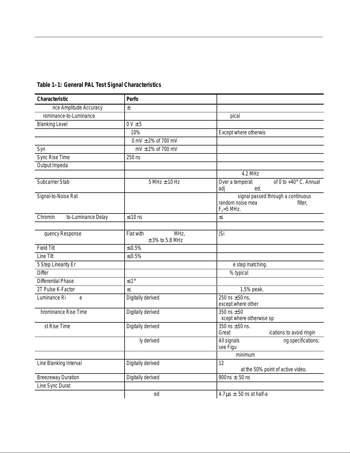
T able1–1: General PAL T est Signal Characteristics
Specifications
Characteristic
Luminance Amplitude Accuracy
Chrominance-to-Luminance Gain
Blanking Level
Rise Time Accuracy
Burst Amplitude
Sync Amplitude
Sync Rise Time
Output Impedance
Return Loss
Subcarrier Stability
Signal-to-Noise Ratio
ББББББББББ
ББББББББББ
Chrominance-to-Luminance Delay
SCH Phase
Frequency Response
Field Tilt
Line Tilt
5 Step Linearity Error
Differential Gain
Differential Phase
2T Pulse K-Factor
Luminance Rise Time
ББББББББББ
Chrominance Rise Time
Burst Rise Time
ББББББББББ
Line Timing
Front Porch Duration
Line Blanking Interval
ББББББББББ
Breezeway Duration
Line Sync Duration
Vertical Serration Duration
Performance Requirements
± 1% of 700 mV
± 2% of 700 mV
0 V ± 50 mV
± 10%
300 mV ± 2% of 700 mV
300 mV ± 2% of 700 mV
250 ns
4.43361875 MHz ± 10 Hz
БББББББББ
БББББББББ
≤ 10 ns
0° ± 5°
Flat within ± 2% to 4.8 MHz,
± 3% to 5.8 MHz
≤ 0.5%
≤ 0.5%
≤ 1%
≤ 1%
≤ 1°
≤ 0.5%
Digitally derived
БББББББББ
Digitally derived
Digitally derived
БББББББББ
Digitally derived
Digitally derived
Digitally derived
БББББББББ
Digitally derived
Digitally derived
Digitally derived
Supplemental Information
1% typical
Except where otherwise specified
75 Ω
≥ 36 dB at 4.2 MHz
Over a temperature range of 0 to +40° C. Annual
adjustment required.
≥ 60 dB; signal passed through a continuous
БББББББББББ
random noise measurement low pass filter,
БББББББББББ
Fc=5 MHz.
≤ 5 ns typical
(Sin x)/x ± 1 dB to 5 MHz
Relative step matching.
≤ 0.5% typical
Ringing ≤ 1.5% peak.
250 ns ±50 ns,
except where otherwise specified.
БББББББББББ
350 ns ±50 ns,
except where otherwise specified.
350 ns ±50 ns.
БББББББББББ
Greater than BBC specifications to avoid ringing.
All signals comply with PAL timing specifications;
see Figures 1–1 through 1–25.
1.55 µs minimum
12.0µs ± 0.15 µs
БББББББББББ
Measured at the 50% point of active video.
900ns ± 50 ns
4.7µs ± 50 ns at half-amplitude
4.7µs ± 50 ns at half-amplitude
TSG 95 Service Manual 1–3
Page 18
Specifications
Á
Á
Á
Á
Á
Á
Á
Á
Á
Á
Á
Á
Á
Á
Á
Á
Á
Á
Á
Á
Á
Á
Á
Á
Á
Á
Á
Á
Á
Á
Á
Á
Á
Á
Á
Á
Á
Á
Á
Á
Á
Á
Á
Á
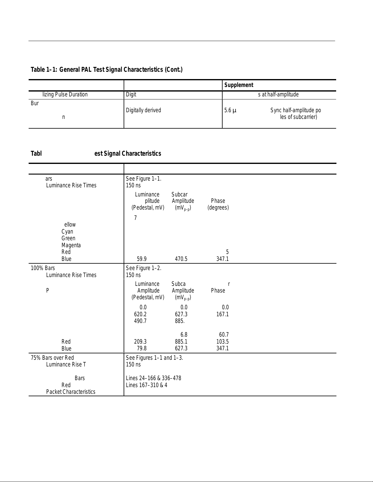
T able1–1: General PAL T est Signal Characteristics (Cont.)
Characteristic
Equalizing Pulse Duration
Performance Requirements
Digitally derived
Burst
БББББББББ
Delay from Sync
Duration
БББББББББ
БББББББББ
Digitally derived
БББББББББ
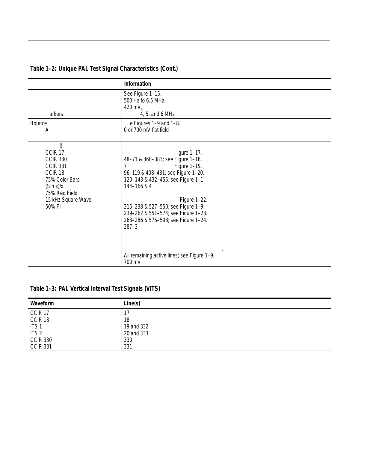
T able1–2: Unique PAL T est Signal Characteristics
Characteristic
75% Bars
БББББББББ
Luminance Rise Times
Packet Characteristics
БББББББББ
БББББББББ
БББББББББ
БББББББББ
БББББББББ
БББББББББ
БББББББББ
White
Y ellow
Cyan
Green
Magenta
Red
Blue
100% Bars
Luminance Rise Times
БББББББББ
Packet Characteristics
БББББББББ
БББББББББ
БББББББББ
БББББББББ
БББББББББ
БББББББББ
White
Y ellow
Cyan
Green
Magenta
Red
Blue
75% Bars over Red
БББББББББ
Luminance Rise Times
Field Timing
БББББББББ
БББББББББ
БББББББББ
Color Bars
Red
Packet Characteristics
Information
See Figure 1–1.
БББББББББББББББББББББ
150 ns
Luminance Subcarrier Subcarrier
Amplitude Amplitude Phase
БББББББББББББББББББББ
(Pedestal, mV) (mV
БББББББББББББББББББББ
700.0 0.0 0.0
БББББББББББББББББББББ
465.1 470.5 167.1
БББББББББББББББББББББ
368.0 663.8 283.5
308.2 620.1 240.7
БББББББББББББББББББББ
216.8 620.1 60.7
БББББББББББББББББББББ
157.0 663.8 103.5
59.9 470.5 347.1
БББББББББББББББББББББ
See Figure 1–2.
150 ns
Luminance Subcarrier Subcarrier
БББББББББББББББББББББ
Amplitude Amplitude Phase
БББББББББББББББББББББ
(Pedestal, mV) (mV
БББББББББББББББББББББ
700.0 0.0 0.0
620.2 627.3 167.1
БББББББББББББББББББББ
490.7 885.1 283.5
БББББББББББББББББББББ
410.9 826.8 240.7
БББББББББББББББББББББ
289.1 826.8 60.7
209.3 885.1 103.5
БББББББББББББББББББББ
79.8 627.3 347.1
See Figures 1–1 and 1–3.
БББББББББББББББББББББ
150 ns
БББББББББББББББББББББ
Lines 24–166 & 336–478
БББББББББББББББББББББ
Lines 167–310 & 479–622
БББББББББББББББББББББ
See 75% Bars, above.
) (degrees)
p–p
) (degrees)
p–p
Supplemental Information
2.35µs ± 50 ns at half-amplitude
БББББББББББ
5.6µs ± 50 ns from Sync half-amplitude point
2.25µs ± 0.1 µs (10 cycles of subcarrier)
БББББББББББ
1–4 TSG 95 Service Manual
Page 19
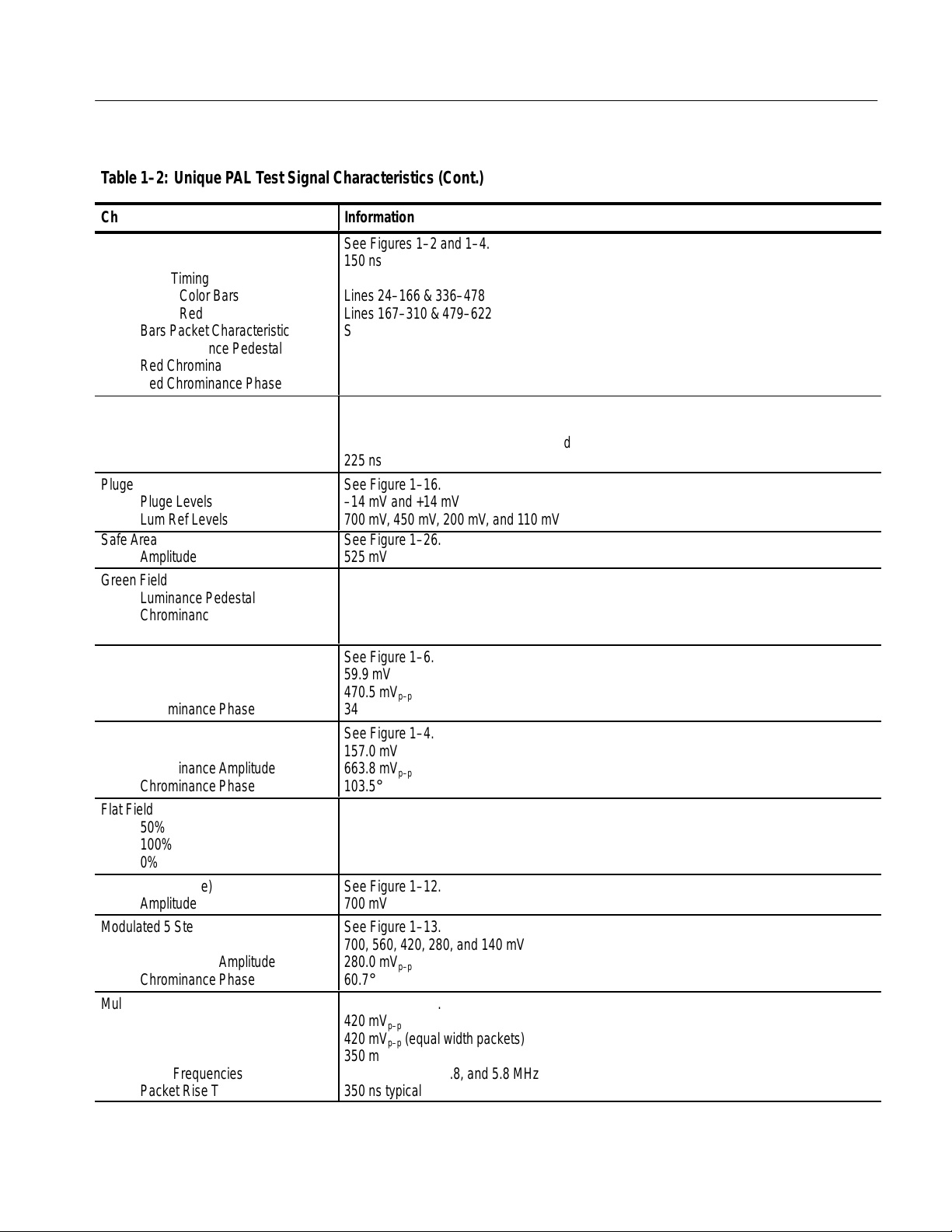
T able1–2: Unique PAL T est Signal Characteristics (Cont.)
Á
Á
Á
Á
Á
Á
Á
Á
Á
Á
Á
Á
Á
Á
Á
Á
Á
Á
Á
Á
Á
Á
Á
Á
Á
Á
Á
Á
Á
Á
Á
Á
Á
Á
Á
Á
Á
Á
Á
Á
Á
Á
Á
Á
Á
Á
Á
Á
Á
Á
Á
Á
Specifications
Characteristic
100% Bars over Red
ББББББББББ
Luminance Rise Times
Field Timing
ББББББББББ
ББББББББББ
ББББББББББ
ББББББББББ
ББББББББББ
Color Bars
Red
Bars Packet Characteristics
Red Luminance Pedestal
Red Chrominance Amplitude
Red Chrominance Phase
Convergence
ББББББББББ
Amplitude
Pattern
ББББББББББ
Pulse HAD
Pluge
ББББББББББ
Pluge Levels
Lum Ref Levels
ББББББББББ
Safe Area
Amplitude
Green Field
ББББББББББ
Luminance Pedestal
Chrominance Amplitude
ББББББББББ
Chrominance Phase
Blue Field
ББББББББББ
Luminance Pedestal
ББББББББББ
Chrominance Amplitude
Chrominance Phase
ББББББББББ
Red Field
Luminance Pedestal
ББББББББББ
Chrominance Amplitude
ББББББББББ
Chrominance Phase
Information
See Figures 1–2 and 1–4.
БББББББББББББББББББББ
150 ns
БББББББББББББББББББББ
Lines 24–166 & 336–478
БББББББББББББББББББББ
Lines 167–310 & 479–622
БББББББББББББББББББББ
See 100% Bars, above.
209.3 mV
БББББББББББББББББББББ
885.1 mV
103.5°
p–p
БББББББББББББББББББББ
See Figures 1–10 and 1–11.
БББББББББББББББББББББ
525.0 mV
19 vert. lines and 14 horiz. lines per field
БББББББББББББББББББББ
225 ns
See Figure 1–16.
БББББББББББББББББББББ
–14 mV and +14 mV
700 mV, 450 mV, 200 mV, and 110 mV
БББББББББББББББББББББ
See Figure 1–26.
525 mV
See Figure 1–5.
БББББББББББББББББББББ
308.2 mV
620.1 mV
БББББББББББББББББББББ
p–p
240.7°
See Figure 1–6.
БББББББББББББББББББББ
59.9 mV
БББББББББББББББББББББ
470.5 mV
347.1°
p–p
БББББББББББББББББББББ
See Figure 1–4.
157.0 mV
БББББББББББББББББББББ
663.8 mV
103.5°
p–p
БББББББББББББББББББББ
Flat Field
50%
ББББББББББ
100%
ББББББББББ
0%
5 Step (Gray Scale)
ББББББББББ
Amplitude
Modulated 5 Step
Luminance Amplitude
ББББББББББ
Chrominance Amplitude
ББББББББББ
Chrominance Phase
Multiburst
White Reference Bar Amplitude
ББББББББББ
Packet Amplitudes
ББББББББББ
Pedestal
ББББББББББ
Burst Frequencies
Packet Rise Time
ББББББББББ
TSG 95 Service Manual 1–5
350 mV; see Figure 1–7.
БББББББББББББББББББББ
700 mV; see Figure 1–8.
БББББББББББББББББББББ
0 mV; see Figure 1–9.
See Figure 1–12.
БББББББББББББББББББББ
700 mV
See Figure 1–13.
700, 560, 420, 280, and 140 mV
БББББББББББББББББББББ
280.0 mV
60.7°
p–p
БББББББББББББББББББББ
See Figure 1–14.
420 mV
БББББББББББББББББББББ
p–p
420 mV
350 mV
0.5, 1.0, 2.0, 4.0, 4.8, and 5.8 MHz
350 ns typical
(equal width packets)
p–p
БББББББББББББББББББББ
БББББББББББББББББББББ
БББББББББББББББББББББ
Page 20
Specifications
Á
Á
Á
Á
Á
Á
Á
Á
Á
Á
Á
Á
Á
Á
Á
Á
Á
Á
Á
Á
Á
Á
Á
Á
Á
Á
Á
Á
Á
Á
Á
Á
Á
Á
Á
Á
Á
Á
Á
T able1–2: Unique PAL T est Signal Characteristics (Cont.)
Characteristic
60% Reduced Line Sweep
БББББББББ
Frequency
Amplitude
БББББББББ
Markers
Bounce
БББББББББ
Amplitude
БББББББББ
Rate
Matrix (Signal)
CCIR 17
БББББББББ
CCIR 330
БББББББББ
CCIR 331
CCIR 18
БББББББББ
75% Color Bars
БББББББББ
(Sin x)/x
БББББББББ
75% Red Field
15 kHz Square Wave
БББББББББ
50% Flat Field
БББББББББ
Shallow Ramp
БББББББББ
UK ITS 1
UK ITS 2
БББББББББ
Field Square Wave
Field Timing
БББББББББ
БББББББББ
Lines (White)
Lines at Blanking
Amplitude
Information
See Figure 1–15.
БББББББББББББББББББББ
500 Hz to 6.5 MHz
420 mV
p–p
БББББББББББББББББББББ
1, 2, 3, 4, 5, and 6 MHz
See Figures 1–9 and 1–8.
БББББББББББББББББББББ
0 or 700 mV flat field
БББББББББББББББББББББ
≈ 1.0 second high, ≈ 1.0 second low
(Lines)
24–47 & 336–359; see Figure 1–17.
БББББББББББББББББББББ
48–71 & 360–383; see Figure 1–18.
БББББББББББББББББББББ
72–95 & 384–407; see Figure 1–19.
96–1 19 & 408–431; see Figure 1–20.
БББББББББББББББББББББ
120–143 & 432–455; see Figure 1–1.
БББББББББББББББББББББ
144–166 & 456–478; see Figure 1–21.
БББББББББББББББББББББ
167–190 & 479–502; see Figure 1–3.
191–214 & 503–526; see Figure 1–22.
БББББББББББББББББББББ
215–238 & 527–550; see Figure 1–9.
БББББББББББББББББББББ
239–262 & 551–574; see Figure 1–23.
БББББББББББББББББББББ
263–286 & 575–598; see Figure 1–24.
287–310 & 599–622; see Figure 1–25.
БББББББББББББББББББББ
БББББББББББББББББББББ
Lines 89–244 (and 401–556); see Figure 1–8.
All remaining active lines; see Figure 1–9.
БББББББББББББББББББББ
700 mV
T able1–3: PAL Vertical Interval Test Signals (VITS)
БББББББББББББББББББББББББББББББ
Waveform
CCIR 17
CCIR 18
БББББББББ
ITS 1
БББББББББ
ITS 2
БББББББББ
CCIR 330
CCIR 331
БББББББББ
1–6 TSG 95 Service Manual
Line(s)
17
18
БББББББББББББББББББББ
19 and 332
БББББББББББББББББББББ
20 and 333
БББББББББББББББББББББ
330
331
БББББББББББББББББББББ
Page 21
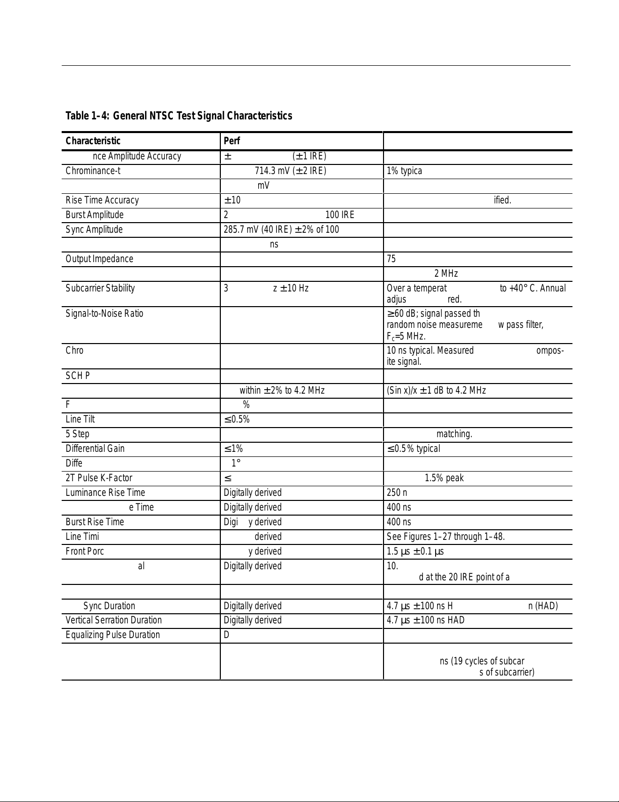
Table 1–4: General NTSC Test Signal Characteristics
Á
Á
Á
Á
Á
Á
Á
Á
Á
Á
Á
Á
Specifications
Characteristic
Luminance Amplitude Accuracy
Chrominance-to-Luminance Gain
Blanking Level
Rise Time Accuracy
Burst Amplitude
Sync Amplitude
Sync Rise Time
Output Impedance
Return Loss
Subcarrier Stability
Signal-to-Noise Ratio
ББББББББББ
ББББББББББ
Chrominance-to-Luminance Delay
SCH Phase
Frequency Response
Field Tilt
Line Tilt
5 Step Linearity Error
Differential Gain
Differential Phase
2T Pulse K-Factor
Luminance Rise Time
Chrominance Rise Time
Burst Rise Time
Line Timing
Front Porch Duration
Line Blanking Interval
ББББББББББ
Breezeway Duration
Line Sync Duration
Vertical Serration Duration
Equalizing Pulse Duration
Burst
Delay from Sync
ББББББББББ
Duration
Performance Requirements
± 1% of 714.3 mV (± 1 IRE)
± 2% of 714.3 mV (± 2 IRE)
0 V ± 50 mV
± 10%
285.7 mV (40 IRE) ± 2% of 100 IRE
285.7 mV (40 IRE) ± 2% of 100 IRE
140 ns ± 20 ns
3.579545 MHz ± 10 Hz
БББББББББ
БББББББББ
≤ 15 ns
0° ± 5°
Flat within ± 2% to 4.2 MHz
≤ 0.5%
≤ 0.5%
≤ 1%
≤ 1%
≤ 1°
≤ 0.5%
Digitally derived
Digitally derived
Digitally derived
Digitally derived
Digitally derived
Digitally derived
БББББББББ
Digitally derived
Digitally derived
Digitally derived
Digitally derived
Digitally derived
БББББББББ
Supplemental Information
1% typical
Except where otherwise specified.
75 Ω
≥ 36 dB at 4.2 MHz
Over a temperature range of 0 to +40° C. Annual
adjustment required.
≥ 60 dB; signal passed through a continuous
БББББББББББ
random noise measurement low pass filter,
Fc=5 MHz.
БББББББББББ
10 ns typical. Measured with the NTC7 Composite signal.
(Sin x)/x ± 1 dB to 4.2 MHz
Relative step matching.
≤ 0.5% typical
Ringing ≤ 1.5% peak
250 ns
400 ns
400 ns
See Figures 1–27 through 1–48.
1.5 µs ± 0.1 µs
10.9 µs ± 0.2 µs
БББББББББББ
Measured at the 20 IRE point of active video.
600 ns ± 100 ns
4.7 µs ± 100 ns Half-amplitude duration (HAD)
4.7 µs ± 100 ns HAD
2.3 µs ± 100 ns HAD
5.308 µs ±35 ns (19 cycles of subcarrier)
БББББББББББ
2.51 µs ± 0.1 µs (9 cycles of subcarrier)
TSG 95 Service Manual 1–7
Page 22
Specifications
Á
Á
Á
Á
Á
Á
Á
Á
Á
Á
Á
Á
Á
Á
Á
Á
Á
Á
Á
Á
Á
Á
Á
Á
Á
Á
Á
Á
Á
Á
Á
Á
Á
Á
Á
Á
Á
Á
Á
Á
Á
Á
Á
Á
Á
Á
Á
Á
Á
Á
Á
Á
Á
Á
Á
Á
Á
Á
Á
Á
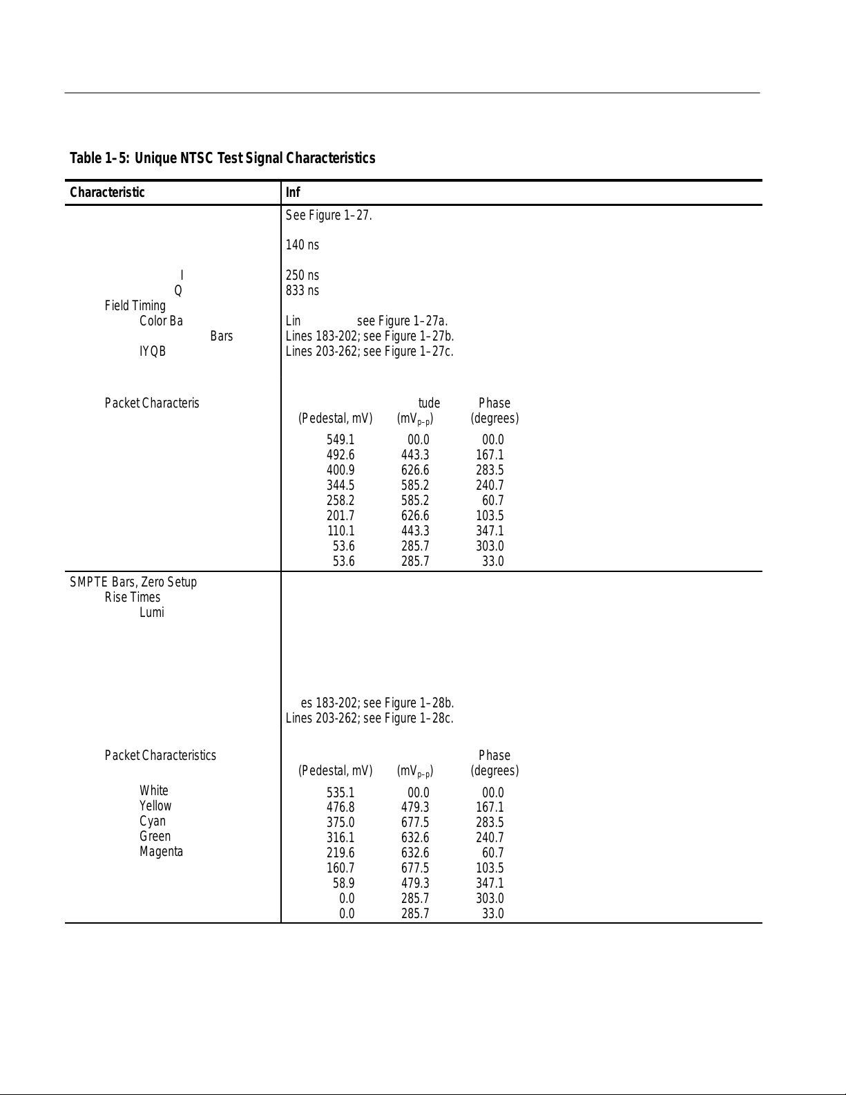
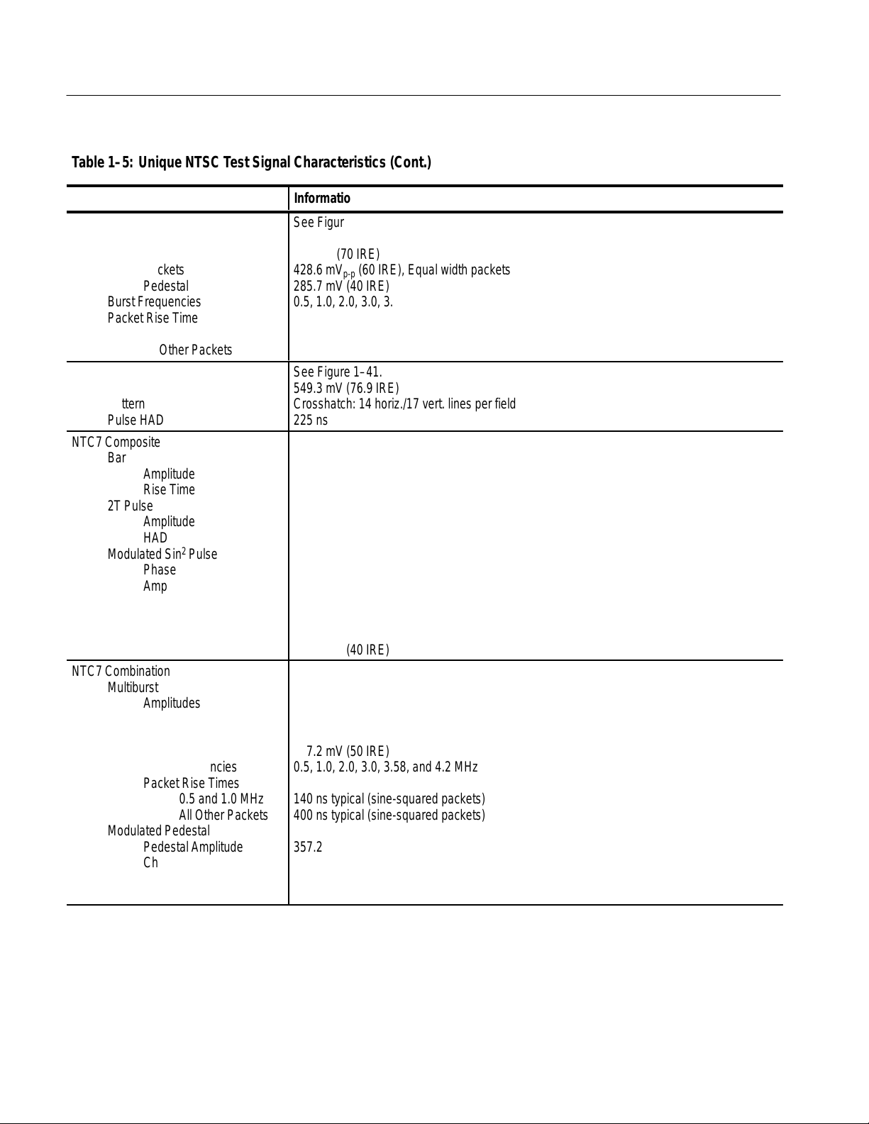
Table 1–5: Unique NTSC Test Signal Characteristics
Characteristic
SMPTE Bars
БББББББББ
Rise Times
БББББББББ
БББББББББ
БББББББББ
БББББББББ
БББББББББ
БББББББББ
БББББББББ
БББББББББ
БББББББББ
БББББББББ
БББББББББ
БББББББББ
БББББББББ
БББББББББ
Luminance
Chrominance
–I
Q
Field Timing
Color Bars
Reverse Blue Bars
IYQB
Packet Characteristics
White
Y ellow
Cyan
Green
Magenta
Red
Blue
–I
Q
SMPTE Bars, Zero Setup
БББББББББ
Rise Times
БББББББББ
БББББББББ
БББББББББ
БББББББББ
БББББББББ
БББББББББ
Luminance
Chrominance
–I
Q
Field Timing
Color Bars
Reverse Blue Bars
IYQB
Information
See Figure 1–27.
БББББББББББББББББББББ
140 ns
БББББББББББББББББББББ
БББББББББББББББББББББ
250 ns
833 ns
БББББББББББББББББББББ
БББББББББББББББББББББ
Lines 21-182; see Figure 1–27a.
БББББББББББББББББББББ
Lines 183-202; see Figure 1–27b.
Lines 203-262; see Figure 1–27c.
БББББББББББББББББББББ
Luminance Subcarrier Subcarrier
БББББББББББББББББББББ
Amplitude Amplitude Phase
(Pedestal, mV) (mV
БББББББББББББББББББББ
549.1 00.0 00.0
БББББББББББББББББББББ
492.6 443.3 167.1
БББББББББББББББББББББ
400.9 626.6 283.5
БББББББББББББББББББББ
344.5 585.2 240.7
258.2 585.2 60.7
БББББББББББББББББББББ
201.7 626.6 103.5
БББББББББББББББББББББ
110.1 443.3 347.1
53.6 285.7 303.0
БББББББББББББББББББББ
) (degrees)
p–p
53.6 285.7 33.0
See Figure 1–28.
БББББББББББББББББББББ
БББББББББББББББББББББ
140 ns
БББББББББББББББББББББ
250 ns
БББББББББББББББББББББ
833 ns
БББББББББББББББББББББ
Lines 21-182; see Figure 1–28.
БББББББББББББББББББББ
Lines 183-202; see Figure 1–28b.
БББББББББББББББББББББ
Lines 203-262; see Figure 1–28c.
Luminance Subcarrier Subcarrier
Packet Characteristics
БББББББББ
БББББББББ
БББББББББ
БББББББББ
БББББББББ
БББББББББ
БББББББББ
БББББББББ
1–8 TSG 95 Service Manual
White
Y ellow
Cyan
Green
Magenta
Red
Blue
–I
Q
Amplitude Amplitude Phase
БББББББББББББББББББББ
(Pedestal, mV) (mV
БББББББББББББББББББББ
535.1 00.0 00.0
БББББББББББББББББББББ
476.8 479.3 167.1
375.0 677.5 283.5
БББББББББББББББББББББ
316.1 632.6 240.7
БББББББББББББББББББББ
219.6 632.6 60.7
БББББББББББББББББББББ
160.7 677.5 103.5
58.9 479.3 347.1
БББББББББББББББББББББ
БББББББББББББББББББББ
0.0 285.7 303.0
0.0 285.7 33.0
) (degrees)
p–p
Page 23
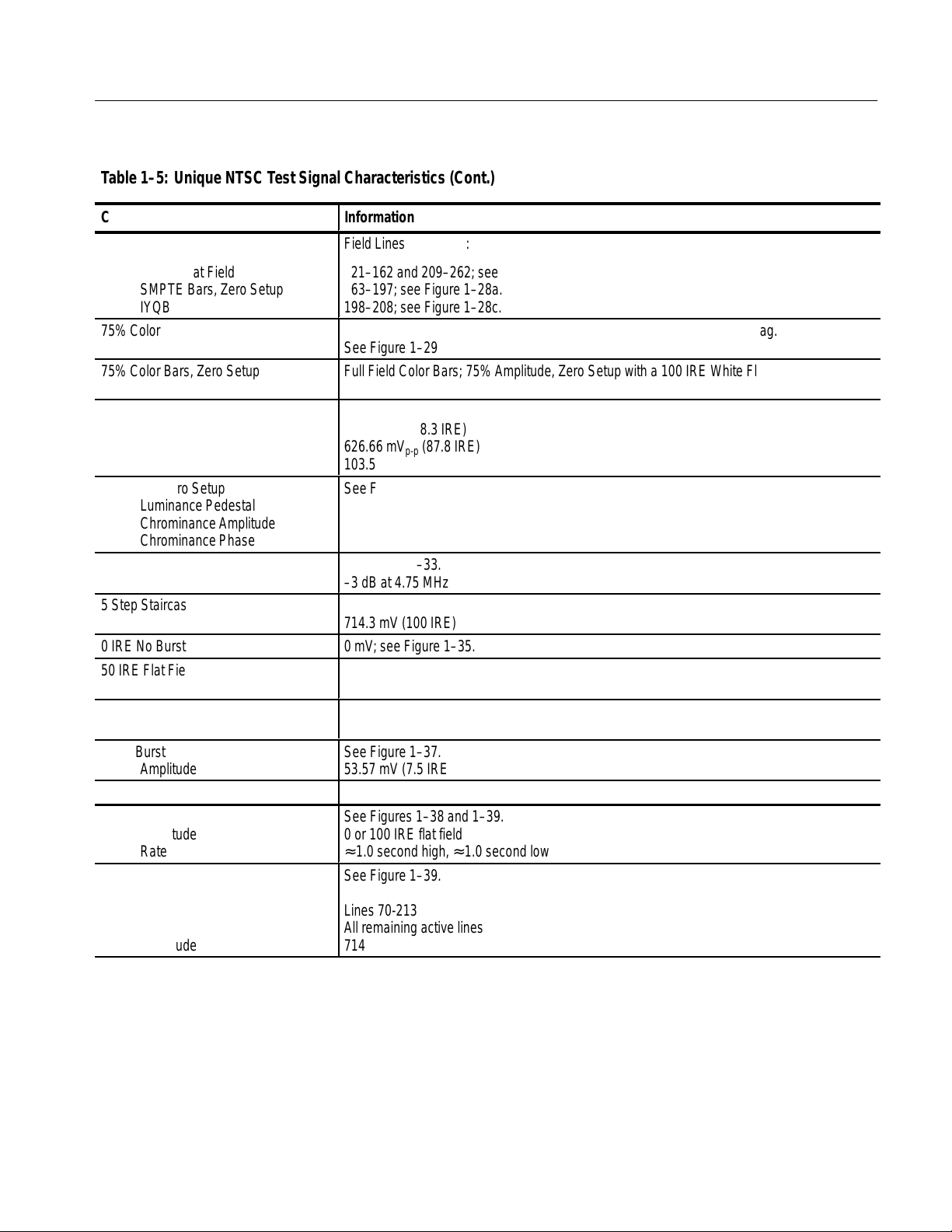
T able1–5: Unique NTSC Test Signal Characteristics (Cont.)
Á
Á
Á
Á
Á
Á
Á
Á
Á
Á
Á
Á
Á
Á
Á
Á
Á
Á
Á
Á
Á
Á
Á
Á
Á
Á
Á
Á
Á
Á
Á
Á
Á
Á
Á
Á
Specifications
Characteristic
SNG Bars (Matrix), Zero Setup Only
ББББББББББ
30 IRE Flat Field
ББББББББББ
SMPTE Bars, Zero Setup
ББББББББББ
IYQB
75% Color Bars
ББББББББББ
75% Color Bars, Zero Setup
ББББББББББ
Red Field
ББББББББББ
Luminance Pedestal
Chrominance Amplitude
ББББББББББ
Chrominance Phase
Red Field, Zero Setup
ББББББББББ
Luminance Pedestal
ББББББББББ
Chrominance Amplitude
Chrominance Phase
ББББББББББ
(Sin x)⁄x
Spectrum
5 Step Staircase
ББББББББББ
Amplitude
0 IRE No Burst
50 IRE Flat Field
ББББББББББ
Amplitude
100 IRE Flat Field
Amplitude
Black Burst
ББББББББББ
Amplitude
Black Burst, Zero Setup
Bounce
ББББББББББ
Amplitude
Rate
ББББББББББ
Field Square Wave
Field Timing
ББББББББББ
ББББББББББ
ББББББББББ
Lines (White)
Lines at Blanking
Amplitude
Information
Field Lines (inclusive):
БББББББББББББББББББББ
21–162 and 209–262; see Figure 1–36.
БББББББББББББББББББББ
163–197; see Figure 1–28a.
БББББББББББББББББББББ
198–208; see Figure 1–28c.
Full Field Color Bars; 75% Amplitude, 7.5% Setup with a 100 IRE White Flag.
See Figure 1–29
БББББББББББББББББББББ
Full Field Color Bars; 75% Amplitude, Zero Setup with a 100 IRE White Flag.
БББББББББББББББББББББ
See Figure 1–30.
See Figure 1–31.
БББББББББББББББББББББ
201.74 mV (28.3 IRE)
626.66 mV
БББББББББББББББББББББ
(87.8 IRE)
p-p
103.5_
See Figure 1–32.
БББББББББББББББББББББ
160.14 mV (22.4 IRE)
БББББББББББББББББББББ
677.08 mV
103.5_
БББББББББББББББББББББ
(94.8 IRE)
p-p
See Figure 1–33.
–3 dB at 4.75 MHz
See Figure 1–34.
БББББББББББББББББББББ
714.3 mV (100 IRE)
0 mV; see Figure 1–35.
See Figure 1–36.
БББББББББББББББББББББ
357.2 mV
See Figure 1–39.
714.3 mV
See Figure 1–37.
БББББББББББББББББББББ
53.57 mV (7.5 IRE)
0 mV (0 IRE); see Figure 1–38.
See Figures 1–38 and 1–39.
БББББББББББББББББББББ
0 or 100 IRE flat field
≈ 1.0 second high, ≈ 1.0 second low
БББББББББББББББББББББ
See Figure 1–39.
БББББББББББББББББББББ
Lines 70-213
БББББББББББББББББББББ
All remaining active lines
714.3 mV (100 IRE)
БББББББББББББББББББББ
TSG 95 Service Manual 1–9
Page 24
Specifications
Á
Á
Á
Á
Á
Á
Á
Á
Á
Á
Á
Á
Á
Á
Á
Á
Á
Á
Á
Á
Á
Á
Á
Á
Á
Á
Á
Á
Á
Á
Á
Á
Á
Á
Á
Á
Á
Á
Á
Á
Á
Á
Á
Á
Á
Á
Á
Á
Á
Á
Á
Á
Á
Á
Á
Á
T able1–5: Unique NTSC Test Signal Characteristics (Cont.)
Characteristic
Multiburst
БББББББББ
Amplitudes
БББББББББ
БББББББББ
БББББББББ
БББББББББ
БББББББББ
White Reference Bar
Packets
Pedestal
Burst Frequencies
Packet Rise Time
0.5 MHz
All Other Packets
Convergence
БББББББББ
Amplitude
Pattern
БББББББББ
Pulse HAD
NTC7 Composite
БББББББББ
Bar
БББББББББ
БББББББББ
БББББББББ
БББББББББ
БББББББББ
БББББББББ
БББББББББ
БББББББББ
БББББББББ
Amplitude
Rise Time
2T Pulse
Amplitude
HAD
2
Modulated Sin
Pulse
Phase
Amplitude
HAD
Modulate 5 Step Staircase
Luminance
Chrominance
NTC7 Combination
Multiburst
БББББББББ
БББББББББ
БББББББББ
БББББББББ
БББББББББ
БББББББББ
БББББББББ
БББББББББ
БББББББББ
БББББББББ
1–10 TSG 95 Service Manual
Amplitudes
White Bar
Packets
Pedestal
Burst Frequencies
Packet Rise Times
0.5 and 1.0 MHz
All Other Packets
Modulated Pedestal
Pedestal Amplitude
Chrominance Amplitudes
Phase
Rise Time
Information
See Figure 1–40.
БББББББББББББББББББББ
500 mV (70 IRE)
БББББББББББББББББББББ
428.6 mV
БББББББББББББББББББББ
285.7 mV (40 IRE)
БББББББББББББББББББББ
0.5, 1.0, 2.0, 3.0, 3.58, and 4.2 MHz
БББББББББББББББББББББ
140 ns typical (sine-squared packets)
БББББББББББББББББББББ
400 ns typical (sine-squared packets)
(60 IRE), Equal width packets
p-p
See Figure 1–41.
БББББББББББББББББББББ
549.3 mV (76.9 IRE)
Crosshatch: 14 horiz./17 vert. lines per field
БББББББББББББББББББББ
225 ns
See Figure 1–42.
БББББББББББББББББББББ
714.3 mV (100 IRE)
БББББББББББББББББББББ
125 ns
БББББББББББББББББББББ
БББББББББББББББББББББ
714.3 mV (100 IRE)
250 ns
БББББББББББББББББББББ
БББББББББББББББББББББ
60.8° ± 1°
БББББББББББББББББББББ
714.3 mV (100 IRE) at peak amplitude
1.563 µs
БББББББББББББББББББББ
БББББББББББББББББББББ
642.9 mV (90 IRE)
БББББББББББББББББББББ
285.7 mV (40 IRE)
See Figure 1–43.
БББББББББББББББББББББ
БББББББББББББББББББББ
714.3 mV (100 IRE)
357.2 mV (50 IRE)
БББББББББББББББББББББ
357.2 mV (50 IRE)
БББББББББББББББББББББ
0.5, 1.0, 2.0, 3.0, 3.58, and 4.2 MHz
БББББББББББББББББББББ
140 ns typical (sine-squared packets)
БББББББББББББББББББББ
400 ns typical (sine-squared packets)
БББББББББББББББББББББ
БББББББББББББББББББББ
357.2 mV (50 IRE)
142.9 mV (20 IRE), 285.7 mV (40 IRE), and 571.4 mV (80 IRE)
БББББББББББББББББББББ
90°
БББББББББББББББББББББ
400 ns
Page 25
T able1–5: Unique NTSC Test Signal Characteristics (Cont.)
Á
Á
Á
Á
Á
Á
Á
Á
Á
Á
Á
Á
Á
Á
Á
Á
Á
Á
Á
Á
Á
Á
Á
Á
Á
Á
Á
Á
Á
Á
Á
Á
Á
Á
Á
Á
Á
Á
Á
Á
Á
Á
Á
Á
Á
Á
Á
Á
Á
Á
Á
Á
Á
Á
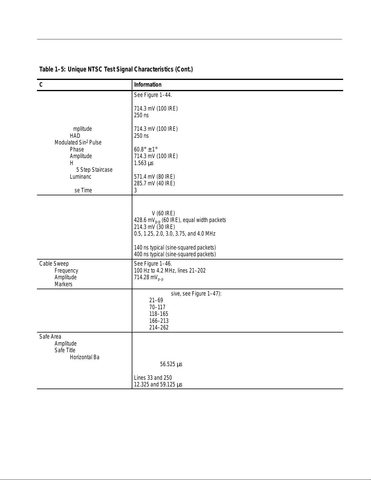
Specifications
Characteristic
FCC Composite
ББББББББББ
Bar
ББББББББББ
ББББББББББ
ББББББББББ
ББББББББББ
ББББББББББ
ББББББББББ
ББББББББББ
ББББББББББ
ББББББББББ
Amplitude
Rise Time
2T Pulse
Amplitude
HAD
2
Modulated Sin
Pulse
Phase
Amplitude
HAD
Modulate 5 Step Staircase
Luminance
Chrominance
Rise Time
Cable Multiburst
ББББББББББ
Amplitudes
ББББББББББ
ББББББББББ
ББББББББББ
ББББББББББ
ББББББББББ
White Reference Bar
Packets
Pedestal
Burst Frequencies
Packet Rise Time
0.5 MHz
All Other Packets
Cable Sweep
ББББББББББ
Frequency
ББББББББББ
Amplitude
Markers
ББББББББББ
Matrix
NTC7 Composite
ББББББББББ
NTC7 Combination
Color Bars
ББББББББББ
(Sin x)/x
ББББББББББ
50 IRE Flat Field
Safe Area
ББББББББББ
Amplitude
Safe Title
ББББББББББ
ББББББББББ
ББББББББББ
ББББББББББ
TSG 95 Service Manual 1–11
Horizontal Bar
Vertical Timing
Safe Action
Horizontal Bar
Vertical Timing
Information
See Figure 1–44.
БББББББББББББББББББББ
714.3 mV (100 IRE)
БББББББББББББББББББББ
250 ns
БББББББББББББББББББББ
БББББББББББББББББББББ
714.3 mV (100 IRE)
250 ns
БББББББББББББББББББББ
БББББББББББББББББББББ
60.8° ± 1°
БББББББББББББББББББББ
714.3 mV (100 IRE)
1.563 µs
БББББББББББББББББББББ
БББББББББББББББББББББ
571.4 mV (80 IRE)
285.7 mV (40 IRE)
БББББББББББББББББББББ
375 ns
See Figure 1–45.
БББББББББББББББББББББ
БББББББББББББББББББББ
428.6 mV (60 IRE)
428.6 mV
БББББББББББББББББББББ
214.3 mV (30 IRE)
БББББББББББББББББББББ
0.5, 1.25, 2.0, 3.0, 3.75, and 4.0 MHz
БББББББББББББББББББББ
140 ns typical (sine-squared packets)
БББББББББББББББББББББ
(60 IRE), equal width packets
p-p
400 ns typical (sine-squared packets)
See Figure 1–46.
БББББББББББББББББББББ
100 Hz to 4.2 MHz, lines 21–202
БББББББББББББББББББББ
714.28 mV
.5, 1, 2, 3, 3.75, and 4 MHz, lines 203–263
БББББББББББББББББББББ
(100 IRE)
p–p
Field Lines (inclusive, see Figure 1–47):
21–69
БББББББББББББББББББББ
70–1 17
118–165
БББББББББББББББББББББ
166–213
БББББББББББББББББББББ
214–262
See Figure 1–48.
БББББББББББББББББББББ
549.1 mV (76.9 IRE)
БББББББББББББББББББББ
Lines 45 and 238
БББББББББББББББББББББ
14.925 and 56.525 µs
БББББББББББББББББББББ
Lines 33 and 250
БББББББББББББББББББББ
12.325 and 59.125 µs
Page 26
Specifications
Á
Á
Á
Á
Á
Á
Á
Á
Á
Á
Á
Á
Á
Á
Á
Á
Á
Á
Á
Á
Á
Á
Á
Á
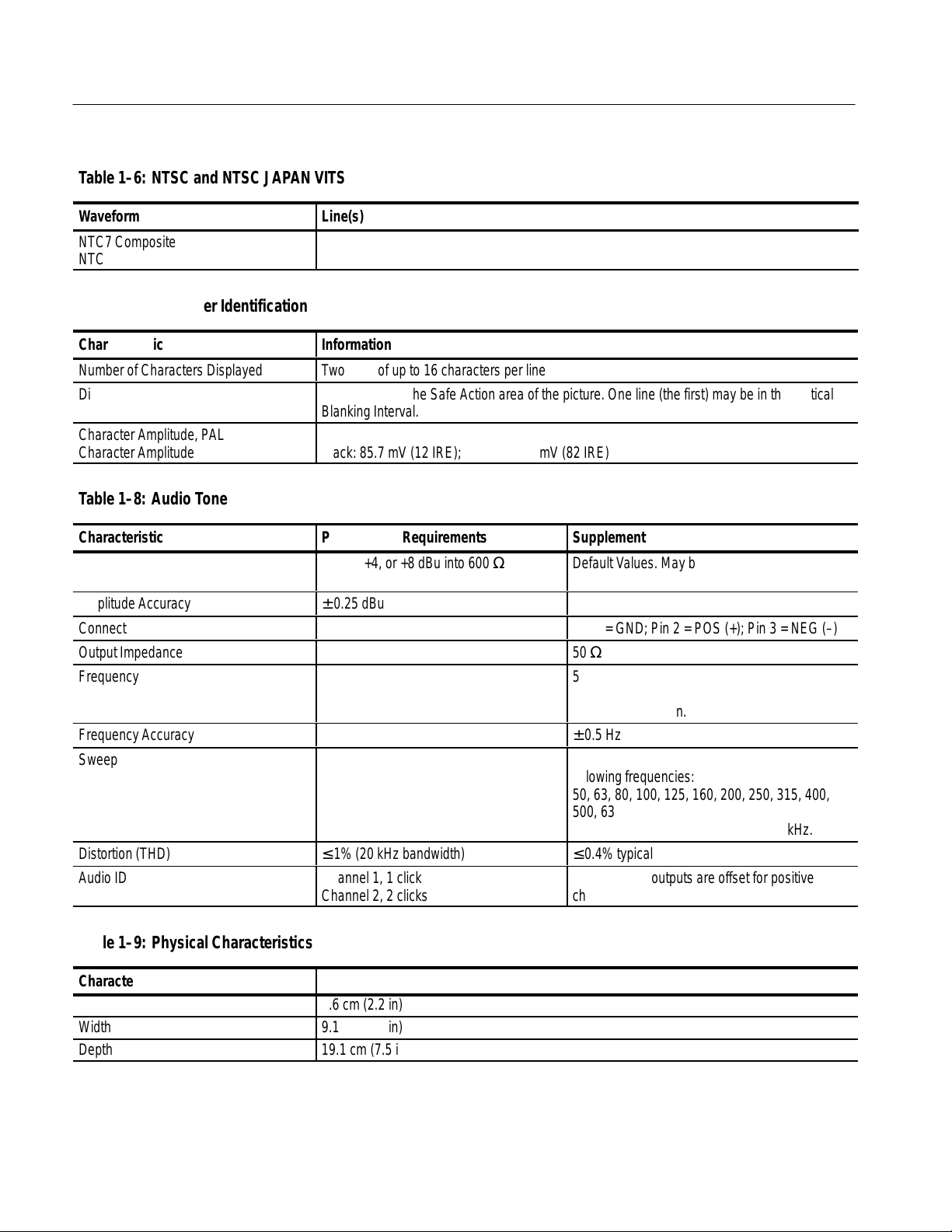
T able1–6: NTSC and NTSC JAPAN VITS
Waveform
NTC7 Composite
БББББББББ
NTC7 Combination
T able1–7: Character Identification
Characteristic
Number of Characters Displayed
Display Position
БББББББББ
Character Amplitude, PAL
БББББББББ
Character Amplitude, NTSC
T able1–8: Audio Tone
Characteristic
БББББББББ
Amplitude
Amplitude Accuracy
Connector Polarity
Output Impedance
Frequency
БББББББББ
БББББББББ
Frequency Accuracy
Sweep
БББББББББ
БББББББББ
БББББББББ
Distortion (THD)
Audio ID “click” (click ON)
Line(s)
17
БББББББББББББББББББББ
280
Information
Two lines of up to 16 characters per line
Movable within the Safe Action area of the picture. One line (the first) may be in the Vertical
БББББББББББББББББББББ
Blanking Interval.
Black: 105 mV; White: 630mV
БББББББББББББББББББББ
Black: 85.7 mV (12 IRE); White: 585.7 mV (82 IRE)
Performance Requirements
БББББББББ
–10, 0, +4, or +8 dBu into 600 Ω
Supplemental Information
БББББББББББ
Default Values. May be recalibrated by qualified
technicians.
± 0.25 dBu
Pin 1 = GND; Pin 2 = POS (+); Pin 3 = NEG (–)
50 Ω
БББББББББ
БББББББББ
50, 63, 125, 250, and 400 Hz; 1, 2, 4, 8, 10, 12.5,
БББББББББББ
16, and 20 kHz; Sweep; Three User frequencies
БББББББББББ
with 1 Hz resolution.
± 0.5 Hz
1 kHz for 5 s followed by 0.5 s at each of the
БББББББББ
БББББББББ
БББББББББ
≤ 1% (20 kHz bandwidth)
Channel1, 1 click
Channel 2, 2 clicks
following frequencies:
БББББББББББ
50, 63, 80, 100, 125, 160, 200, 250, 315, 400,
БББББББББББ
500, 630, and 800 Hz; then 1, 1.25, 1.6, 2, 2.5,
3.15, 4, 5, 6.3, 8, 10, 12.4, 16, and 20 kHz.
БББББББББББ
≤ 0.4% typical
Channel click outputs are offset for positive
channel identification.
T able1–9: Physical Characteristics
Characteristic
Height
Width
Depth
1–12 TSG 95 Service Manual
Information
5.6 cm (2.2 in)
9.1 cm (3.6 in)
19.1 cm (7.5 in)
Page 27
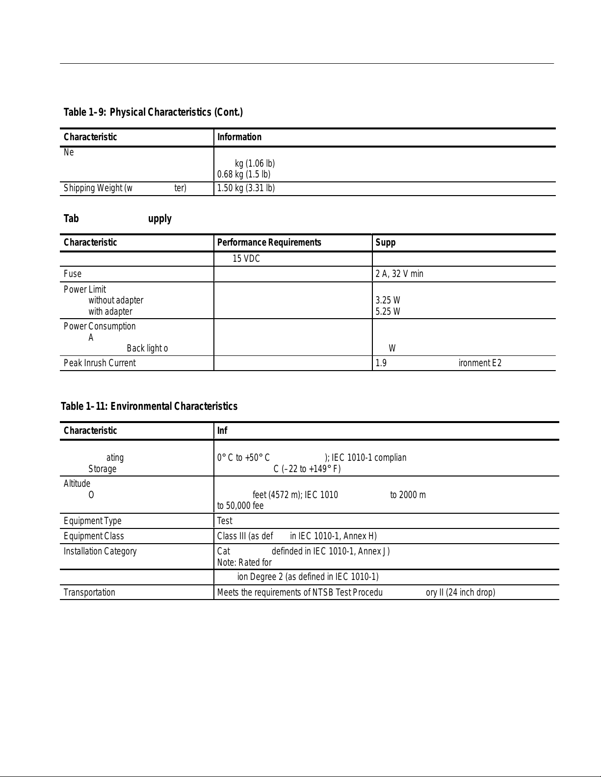
T able1–9: Physical Characteristics (Cont.)
Á
Á
Á
Á
Á
Á
Á
Á
Á
Á
Á
Á
Á
Á
Á
Á
Á
Á
Specifications
Characteristic
Information
Net Weight
ББББББББББ
TSG95
TSG95 with battery pack
ББББББББББ
Shipping Weight (with AC adapter)
БББББББББББББББББББББ
0.48 kg (1.06 lb)
0.68 kg (1.5 lb)
БББББББББББББББББББББ
1.50 kg (3.31 lb)
T able1–10:Power Supply
Characteristic
DC Input Range
Fuse
Power Limit
ББББББББББ
without adapter
with adapter
ББББББББББ
Power Consumption
Audio and Back light off
ББББББББББ
Audio and Back light on
Peak Inrush Current
Performance Requirements
9 to 15 VDC
БББББББББ
БББББББББ
БББББББББÁБББББББББББ
T able1–11: Environmental Characteristics
Supplemental Information
2 A, 32 V min
БББББББББББ
3.25 W
5.25 W
БББББББББББ
Typical (not charging):
2.0 W
2.5 W
1.95 A @230 VAC, Environment E2
Characteristic Information
Temperature
Operating
ББББББББББ
Storage
0° C to +50° C (32 to +122° F); IEC 1010-1 compliance to +40° C
ББББББББББББББББББББББ
–30° C to +65° C (–22 to +149° F)
Altitude
ББББББББББ
Operating
Storage
ББББББББББ
Equipment Type
Equipment Class
Installation Category
ББББББББББББББББББББББ
to 15,000 feet (4572 m); IEC 1010-1 compliance to 2000 m
to 50,000 feet (15420 m)
ББББББББББББББББББББББ
Test
Class III (as defined in IEC 1010-1, Annex H)
Category II (as definded in IEC 1010-1, Annex J)
Note: Rated for indoor use only.
Pollution Degree
Transportation
Pollution Degree 2 (as defined in IEC 1010-1)
Meets the requirements of NTSB Test Procedure 1A, category II (24 inch drop)
TSG 95 Service Manual 1–13
Page 28
Specifications
PAL Waveform Diagrams
NOTE. Time references in the following waveform diagrams apply to the signal half-amplitude points or pulse peaks, unless indicated otherwise.
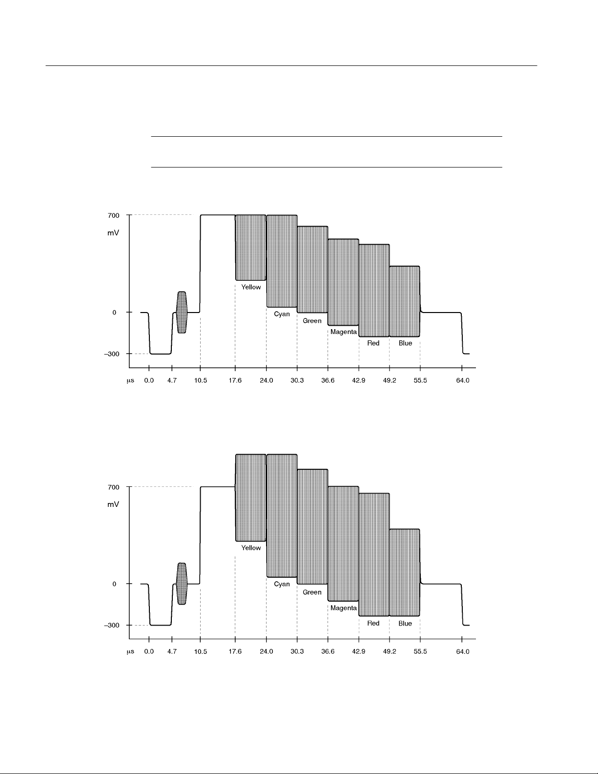
Figure 1–1: PAL 75% Color Bars
Figure 1–2: PAL 100% Color Bars
1–14 TSG 95 Service Manual
Page 29
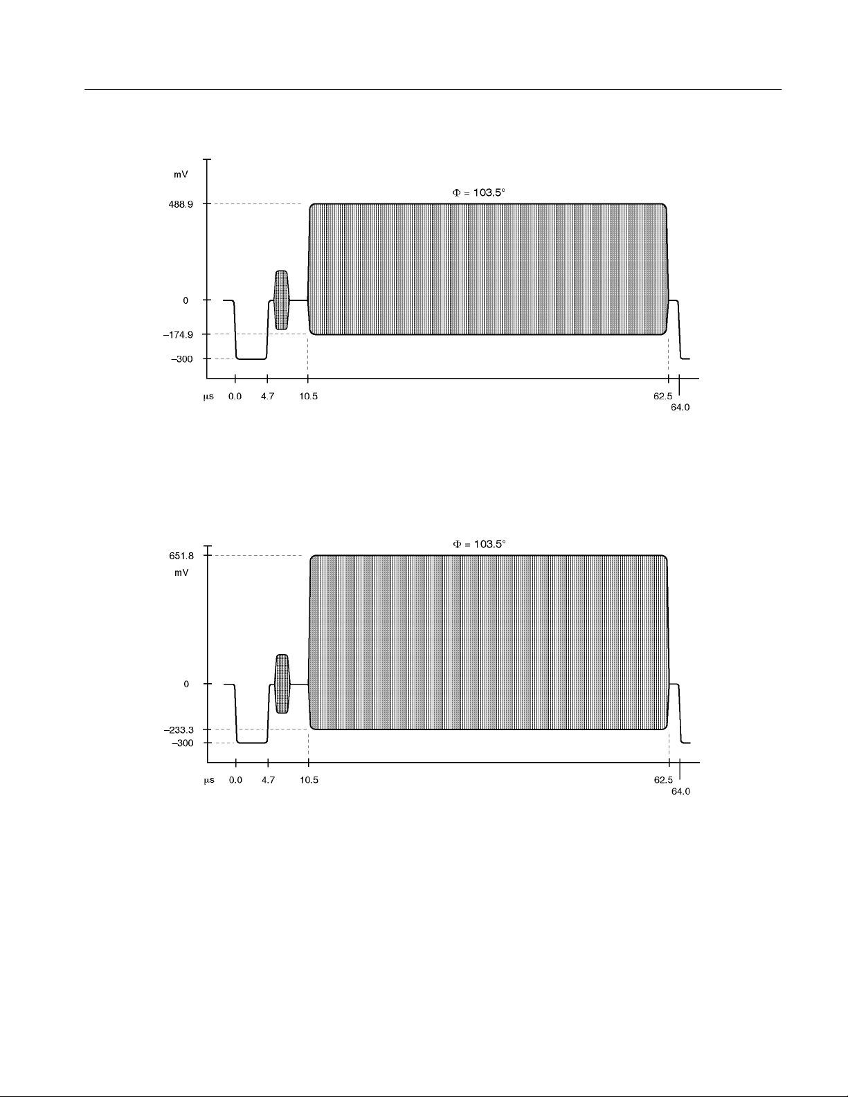
Figure 1–3: PAL 75% Red and Red Field
Specifications
Figure 1–4: PAL 100% Red
TSG 95 Service Manual 1–15
Page 30
Specifications
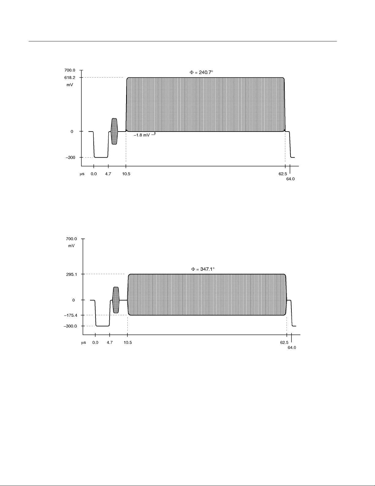
Figure 1–5: PAL Green Field
Figure 1–6: PAL Blue Field
1–16 TSG 95 Service Manual
Page 31

Figure 1–7: PAL 50% Flat Field
Specifications
Figure 1–8: PAL 100% Flat Field
TSG 95 Service Manual 1–17
Page 32

Specifications
Figure 1–9: PAL 0% Flat Field
Figure 1–10: PAL Convergence (vertical lines)
1–18 TSG 95 Service Manual
Page 33

Figure 1–11: PAL Convergence (horizontal lines)
Specifications
Figure 1–12: PAL 5 Step (Gray Scale)
TSG 95 Service Manual 1–19
Page 34

Specifications
Figure 1–13: PAL Modulated 5 Step
Figure 1–14: PAL Multiburst
1–20 TSG 95 Service Manual
Page 35
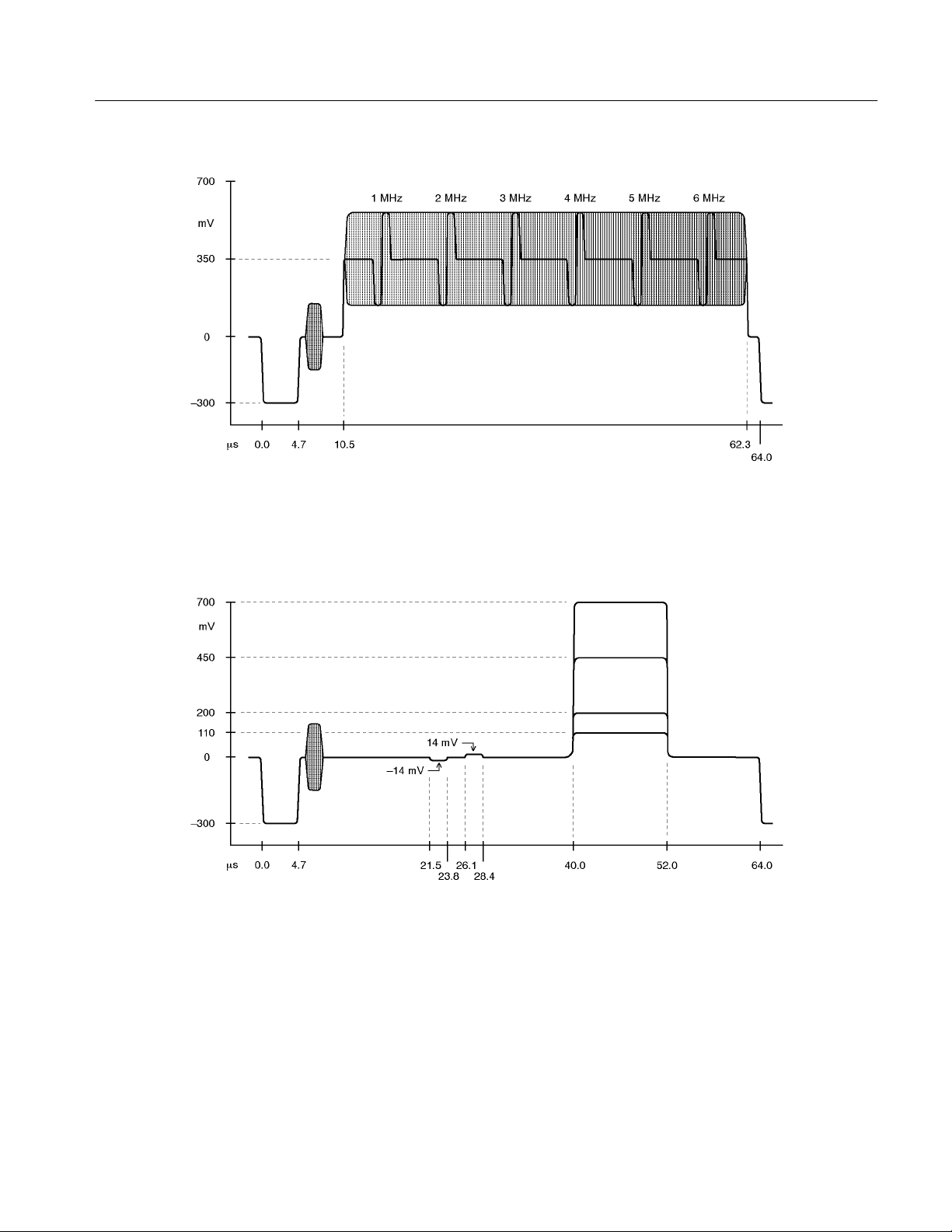
Figure 1–15: PAL Reduced Sweep
Specifications
Figure 1–16: PAL Pluge
TSG 95 Service Manual 1–21
Page 36

Specifications
Figure 1–17: PAL Matrix Signal — CCIR 17
Figure 1–18: PAL Matrix Signal — CCIR Line 330
1–22 TSG 95 Service Manual
Page 37

Figure 1–19: PAL Matrix Signal — CCIR Line 331
Specifications
Figure 1–20: PAL Matrix Signal — CCIR 18
TSG 95 Service Manual 1–23
Page 38

Specifications
Figure 1–21: PAL Matrix Signal — (Sin x)/x
Figure 1–22: PAL Matrix Signal — 15 kHz Square W ave
1–24 TSG 95 Service Manual
Page 39

Figure 1–23: PAL Matrix Signal — Shallow Ramp
Specifications
Figure 1–24: PAL Matrix Signal — UK ITS 1
TSG 95 Service Manual 1–25
Page 40

Specifications
Figure 1–25: PAL Matrix Signal — UK ITS 2
1–26 TSG 95 Service Manual
Page 41

Specifications
Figure 1–26: PAL Safe Area
TSG 95 Service Manual 1–27
Page 42

Specifications
NTSC Waveform Diagrams
Figure 1–27: SMPTE (NTSC) Color Bar Components
1–28 TSG 95 Service Manual
Page 43

Specifications
Figure 1–28: SMPTE (NTSC) Color Bars, Zero Setup
TSG 95 Service Manual 1–29
Page 44

Specifications
Figure 1–29: NTSC 75% Color Bars
Figure 1–30: NTSC 75% Color Bars, Zero Setup
1–30 TSG 95 Service Manual
Page 45

Figure 1–31: NTSC Red Field
Specifications
Figure 1–32: NTSC Red Field, Zero Setup
TSG 95 Service Manual 1–31
Page 46

Specifications
Figure 1–33: NTSC (Sin x)/x
Figure 1–34: NTSC 5 Step Staircase (Gray Scale)
1–32 TSG 95 Service Manual
Page 47

Figure 1–35: NTSC 0 IRE No Burst
Specifications
Figure 1–36: NTSC 30 IRE (Zero Setup) and 50 IRE Flat Fields
TSG 95 Service Manual 1–33
Page 48

Specifications
Figure 1–37: NTSC Black Burst
Figure 1–38: NTSC Black Burst, Zero Setup (and Bounce, Low)
1–34 TSG 95 Service Manual
Page 49

Figure 1–39: NTSC 100 IRE, Field Square Wave (and Bounce, High)
Specifications
Figure 1–40: NTSC Multiburst
TSG 95 Service Manual 1–35
Page 50

Specifications
Figure 1–41: NTSC Convergence Components
1–36 TSG 95 Service Manual
Page 51
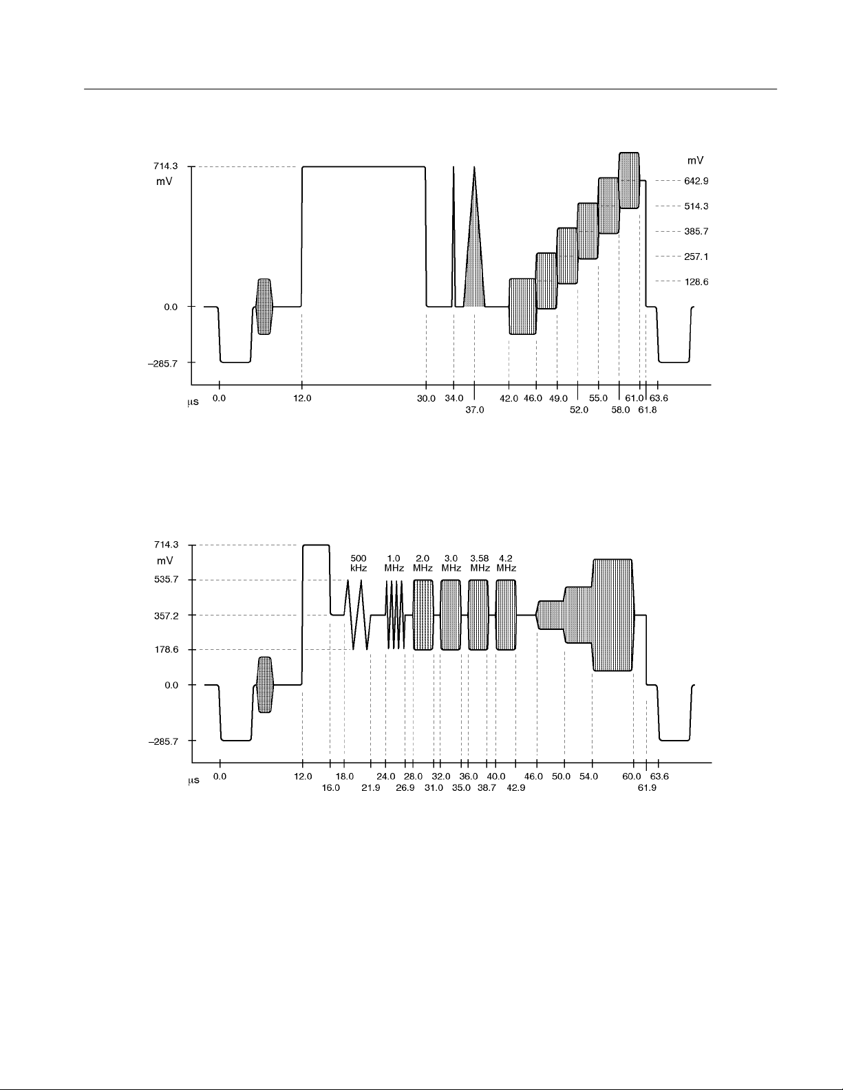
Figure 1–42: NTC7 (NTSC) Composite
Specifications
Figure 1–43: NTC7 (NTSC) Combination
TSG 95 Service Manual 1–37
Page 52

Specifications
Figure 1–44: FCC (NTSC) Composite
Figure 1–45: NTSC Cable Multiburst
1–38 TSG 95 Service Manual
Page 53
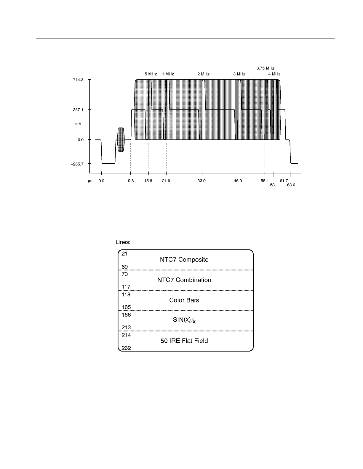
Figure 1–46: NTSC Cable Sweep
Specifications
Figure 1–47: NTSC Matrix
TSG 95 Service Manual 1–39
Page 54

Specifications
Figure 1–48: NTSC Safe Area
1–40 TSG 95 Service Manual
Page 55

Operating Information
This section duplicates material contained in the TSG 95 User manual (Tektronix
part number 070-8916-XX). This material is included for your convenience.
Please check the User manual if you need additional information on any topic.
TSG 95 Service Manual 2–1
Page 56

Operating Information
Getting Started
Please read the following statements before using your new TSG 95, then see the
rest of the section for tips on supplying power, making preliminary settings, and
connecting the instrument.
CAUTION. Attempting to operate the TSG 95 with an improper AC adapter can
result in damage to the instrument. To avoid damage, USE ONLY AN APPROPRIATE DC POWER SOURCE: Voltage must be 9 to 15 VDC; the connector must have the NEGATIVE contact in the center; and open-circuit voltage of
the power source must not exceed 18 VDC.
For best results, use the AC adapter that is supplied with the instrument. If the
supplied adapter is incorrect for the local AC power supply, contact your nearest
Tektronix representative.
WARNING. Install or replace batteries only with the instrument switched OFF
and the AC adapter disconnected.
Supplying Power
Replace the batteries only with standard AA batteries (1.2–1.5 V, nominal), or
with a Tektronix rechargeable battery pack (p/n 119-4488-00).
If you use NiCad AA batteries or the optional battery pack, be sure to set the
battery type to “rechargeable” through the Utility menu (see page 2–6). Failure
to do so can result in damage to the batteries.
NOTE. Do not disconnect the AC adapter when the TSG 95 is switched on. Some
user settings may be lost, perhaps causing unexpected results the next time the
instrument is switched on.
If you have any questions regarding the operation of this instrument, please contact your nearest Tektronix representative or field office. In the United States and
Canada, you may also call the Tektronix information number, 1-800-TEK-WIDE
(1-800-835-9433), between 8:00 am and 5:00 pm Pacific time.
The TSG 95 is DC powered. You may power it with the standard AC adapter, the
optional 9.6 V NiCad battery pack, eight standard AA batteries, or a “BP” type
battery pack with the correct voltage and polarity. The external DC power connector is on the left side of the instrument.
2–2 TSG 95 Service Manual
Page 57

Operating Information
To install AA batteries or the battery pack, open the battery compartment of the
TSG 95 by pressing down on the cover and sliding it in the direction of the inscribed arrow, as shown above. When the cover tabs line up with the slots in the
case, lift the cover away from the instrument. Install batteries in alternating
directions as indicated by the graphic molded into the “floor” of the battery
compartment. If using the optional battery pack, take the time to identify both
contacts and install the pack properly.
When selecting a power source for your TSG 95, please remember:
H Attempting to use an improper AC adapter can damage the instrument. See
the Caution statement on the previous page.
H There is no need to remove the optional NiCad battery pack for recharging.
The TSG 95 will “trickle charge” the battery pack whenever the standard AC
adapter is used. Recharging the battery pack fully can take up to 16 hours.
NOTE. Charging will occur only if the adapter supplies at least 12V; make sure
that the adapter you use is appropriate for the local AC supply.
H AA batteries are not included with the instrument; obtain them locally.
Rechargeable AA batteries may be used, but they will NOT be recharged
automatically by the AC adapter. To recharge AA batteries, remove them
from the instrument and use an appropriate battery charger. For safety, read
and follow the battery charger instructions. Do NOT attempt to recharge
standard alkaline batteries. Remove Alkaline batteries when the instrument
will be stored or powered with the AC adapter for more than 30 days.
H After a minute with no key press, the TSG 95 will automatically switch to
lock out mode (as if you had pressed the Lock Out key); the display back
light will shut off to conserve battery charge. When you want to resume
keypad input, press Lock Out
to exit lock out mode.
H To guard against battery discharge if you forget to turn the TSG 95 off after
use, enable Auto Power Down through the Utility menu (see page 2–6).
TSG 95 Service Manual 2–3
Page 58

Operating Information
Connecting the TSG95
H The TSG 95 can sense low battery voltage. It will warn you when the charge
is sufficient for approximately ten more minutes of operation. The instrument will shut itself down when the battery voltage becomes too low for
reliable operation. For proper function of these features, the Battery Type
must be set correctly in the Utility menu. Please see “Setting the Battery
Type,” below.
The ON key toggles instrument power On and Off.
Connect the instrument to your equipment as you would any television test signal generator. Use 75W coaxial cable (for video) and be sure that the signal path
is properly terminated.
12
3
You may wish to confirm proper operation of your TSG 95—and gain familiarity
with it—by first connecting it directly to a video or waveform monitor.
Keypad and Display Conventions
Please see the Instruction card (p/n 070-8915-XX) supplied with your TSG 95
for a “tour” of the keypad and an explanation of the display symbols. For your
convenience, the following panels are excerpted from the card.
Pin 1 = GND
Pin 2 = POS (+)
Pin 3 = NEG (–)
2–4 TSG 95 Service Manual
Page 59

Definitions
Operating Information
There are two terms used in this manual that deserve a little explanation:
Signal Set. The group of signals that can be selected through the TSG95 keypad
at a given time. In the pre-programmed signal sets, all of the signals are the same
video standard. You may create a “User” signal set, however, that contains any
combination of PAL and NTSC signals assigned to the letter keys that you find
most convenient.
Preliminary Settings
Choose the Video
Standard/Signal Set
T one Level. One of four pre-defined audio output amplitudes that may be selected
through the Tone menu. The levels (1 through 4) are “named” –10, 0, +4, and +8
dBu and calibrated to those amplitudes when the TSG 95 is manufactured.
Qualified personnel with the appropriate equipment can rename and readjust the
levels within the ranges of –10 to –3 dBu and 0 to +10 dBu. See page 4–29, in
the Performance Verification and Adjustment section of this manual, for
instructions.
Once the TSG 95 is up and running, you should make some settings that depend
on how the instrument will be used. These settings are made through the Utility
menu. Invoke the Utility menu by holding Lock Out down while pressing the
ON key—then make the following configuration selections.
1. Use the
2. Select, with the
propriate to your application. The choices are: PAL; NTSC; NTSC JAPAN
(which includes NTSC signals with 0% Setup); and USER SIG SET (the
user-configurable signal set that can contain up to 26 signals of your
choice—see the User manual for more information).
Y and B keys to scroll to the SELECT STNDRD menu item.
A and " keys, the signal standard or “signal set” that is ap-
3. When the name of the desired signal set is displayed, continue to the Battery
Type, or press any rectangular key to exit the Utility menu and return to normal operation.
TSG 95 Service Manual 2–5
Page 60

Operating Information
Set the Battery Type
Enable (Disable)
Auto Power Down
While still in the Utility menu, use the
Y and B keys to scroll to the BATTERY
TYPE item.
1. Toggle to the selection that matches the type of battery you have installed in
your TSG 95 by pressing either
A or ". The choices are “rechargeable” and
“disposable.” Select rechargeable when using NiCad AA cells or the optional
battery pack; choose disposable when you are using common Alkaline AA
batteries, which cannot be recharged.
2. When the correct battery type is displayed, continue to Auto Power Down, or
press any rectangular key to exit the Utility menu and return to normal operation.
“Auto Power Down” will switch the instrument off when ten minutes have
passed without a key press. Enable this feature when using battery power and
operating in an environment in which unplanned shutdown of the TSG 95 is permissible.
1. While still in the Utility menu, use the
Y and B keys to scroll to the AUTO
PWR DOWN item.
2. Disable/enable Auto Power Down by pressing either
A or ". The new state
will be in effect when you return to normal operation. Enabled Auto Power
Down is indicated by a “rotating line” symbol in the upper-right corner of
the instrument LCD.
Other Settings
3. Use the
Y and B keys to access other Utility menu items, or press any rect-
angular key to exit the menu and resume normal operation.
There are other, less important TSG95 settings that are configured through the
Utility menu and its Calibration submenu. See “The Utility Menu,” beginning on
page 5–4 for more information.
2–6 TSG 95 Service Manual
Page 61

Using Your TSG95
Operating Information
Here is a list of what you can do with your TSG 95. Instructions for each use begin on the indicated page.
H Output either PAL or NTSC video test signals (page 2–8). You can
configure the instrument to generate:
H PAL signals
H NTSC signals
H “NTSC JAPAN” signals that have 0 IRE (instead of 7.5 IRE) setup
H A “User Signal Set” that can contain any combination of PAL, NTSC or
NTSC JAPAN signals that you find convenient.
See page 2–5 for information on choosing a video standard/signal set.
Directions for creating (or editing) your own User signal set appear in the
User manual.
H Generate audio tones (page 2–9). You may:
H Choose one of 13 discrete “factory” frequencies, or select a frequency
sweep that sweeps continuously from 50 Hz to 20 kHz (page 2–9)
H Designate three “User Tones” between 50 Hz and 20 kHz with a
resolution of 1 Hz (page 5–7), and later output one of these frequencies
H Select a factory-calibrated audio output level of –10, 0, +4, or +8 dBu
(page 2–9)
H Recalibrate the audio output to permit selection of any whole dB level
within the ranges of –10 to –3 dBu and 0 to +10 dBu (qualified service
technicians only—see page 4–29)
H Include channel-ID “clicks” in the audio output (page 2–10)
H Add an ID message to the video signal (pages 2–10), edit it (page 2–10), and
place it in the vertical interval or position it where desired in the active video
(page 2–10)
H Store up to eight ID messages for later use (page 2–11)
H Create a sequence of (up to four) stored ID messages that will cycle
continuously in the output (page 2–12)
H Save all the current instrument settings as a “Preset” for later recall (page
2–13)
TSG 95 Service Manual 2–7
Page 62

Operating Information
Á
Á
Á
Á
Á
Outputting Test Signals
1. Connect the TSG 95 to your system and make the appropriate preliminary
settings as described in the Getting Started section of this manual.
2. Switch the instrument on or return to normal operation by pressing either the
Bars or Other Signals key. By default, the instrument “powers up” with the
settings that were in effect when it was last switched off.
Table 2–1: TSG95 Video Test Signals
ББББББББББББББББББББББ
PAL
Signal Set
ББББББ
75% Bars
100% Bars
75% Bars/Red
100% Bars/Red
Convergence
Pluge
Safe Area
Green Field
Blue Field
Red Field
100% Flat Field
50% Flat Field
0% Flat Field
Multiburst
60% Sweep
5-Step
Mod. 5-Step
Matrix
Field Square Wave
Bounce
—
* These signals have 0 IRE setup and differ from the signals with the same name in the
NTSC signal set.
NTSC
Signal Set
ББББББ
SMPTE Bars
75% Bars
Convergence
Safe Area
Red Field
50IRE Flat Field
100IRE Flat Field
Black Burst
5-Step
Multiburst
NTC7 Composite
NTC7 Combination
FCC Composite
Cable Multiburst
Cable Sweep
SIN X/X
Matrix
0 IRE, no Burst
Field Square Wave
Bounce
—
NTSC JAPAN
Signal Set
ББББББ
SMPTE Bars*
75% Bars*
SNG Bars*
Convergence
Safe Area
Red Field*
50IRE Flat Field
100IRE Flat Field
Black Burst*
5-Step
Multiburst
NTC7 Composite
NTC7 Combination
FCC Composite
Cable Multiburst
Cable Sweep
SIN X/X
Matrix*
0 IRE, no Burst
Field Square Wave
Bounce
Key
A
B
C
D
E
F
G
H
I
J
K
L
M
N
O
P
Q
R
S
T
U
Á
3. Select the desired test signal one of four ways:
H Press the Bars key repeatedly to select among the available color bars
signals. The signal will be output as soon as the name is displayed on the
TSG 95 LCD.
H Press the Other Signals key repeatedly to select among the “non-bars”
signals. Again, the signal will be output as soon as its name is displayed
on the LCD.
2–8 TSG 95 Service Manual
Page 63

Operating Information
Outputting Audio Tones
Selecting the Audio
Frequency
H Use the
Y and B keys to scroll through the full list of signals until you
get to the desired signal.
H Press the appropriate letter key (A through U) to “direct-select” the
signal. The available signals and their corresponding keys are listed in
Table 2–1.
H Toggle the audio output On/Off by pressing the Tone On/Off key.4
1. Enter the Tone menu (press Shift, then Tone On/Off). The first menu item is
TONE FREQ.
2. Use the
A and " keys to select the desired frequency. The choices are:
50, 63, 125, 250, and 400 Hz;
1, 2, 4, 8, 10, 12.5, 16, and 20 kHz;
USER1, USER2, USER3; and
SWEEP 50–20K (a 50 Hz–20 kHz sweep)
You may specify the USER# frequencies through the Utility/Calibration
menu; see page 5–7. (Note that there is no default value for USER3;
therefore, the USER3 choice will not appear in a new—or reset—instrument.)
Setting the Audio Tone
Level (Amplitude)
You can pause a sweep at any of its 27 frequency steps (listed in Table 1–8 in
the Characteristics section) by pressing Enter when in the TONE FREQ
menu item and SWEEP 50–20K is selected. The message SWEEP PAUSED
will appear on the display. You may find this capability useful for checking a
problem noticed at a particular frequency while sweeping. Press Enter a second time to resume the frequency sweep.
3. Tone frequencies are in effect as soon as they are indicated on the display.
Scroll down to other Audio menu items with the
B key, or exit the menu by
pressing any rectangular key.
1. In the Audio menu, use the
2. Use the
A and " keys to select the desired level. When manufactured, the
B or Y key to reach the TONE LEVEL item.
four TSG 95 tone levels are designated as –10, 0, +4, and +8 dBu and calibrated to those amplitudes. Qualified technicians may rename and recalibrate
the tone levels to any integer value within the ranges of –10 to –3 dBu and 0
to +10 dBu. See page 4–29 for instructions.
3. The new tone level will be in effect immediately. Scroll to other Audio menu
items with the
B or Y key, or exit the menu by pressing any rectangular key.
TSG 95 Service Manual 2–9
Page 64

Operating Information
Inserting Channel-ID
Clicks in the Audio
Inserting ID Messages
Editing ID Messages
When click is enabled, the instrument will insert a single click into channel 1,
and a double click into channel 2.
1. In the Audio menu, use the
2. Use the
A and " keys to toggle the ID clicks On/Off.
3. Scroll to other Audio menu items with the
B or Y key to reach the CLICK item.
B or Y key, or exit the menu by
pressing any rectangular key.
H Toggle the ID message or cycle on and off by pressing the ID On/Off key.
The status of the ID—on, off, or cyc (cycle)—is indicated on the second line
of the TSG 95 display, as shown in the next illustration.
Only the current ID message may be edited in the TSG 95.. The “current” message is the ID that will appear in the output if ID=on. (The current ID will not
appear in the output when ID=off, and may not appear in the output if ID=cyc,
but it can still be edited and saved in either case.)
Positioning ID Messages
1. Press ID Edit. The current ID message will appear on the LCD.
2. Use the arrow keys to position the blinking underline cursor and enter text
with the alphanumeric keys.
3. Press Enter or one of the rectangular keys to terminate the ID edit; the new
ID will become the current ID. If ID=on, the new ID will be inserted into the
video output.
The current ID can be positioned within the safe area of active video, or the first
line can be placed in the vertical interval.
1. Press Shift, then ID Edit. The LCD will look something like this:
2. Change the horizontal (H) position with the A / " keys and the vertical (V)
position with the
Y / B keys.
The H position can range from ØØ (left edge of safe area) to 69–3n, where n
is the number (1–16) of the right-most character position occupied by the
message. Note that, when editing a short message (n<16) that has been
2–10 TSG 95 Service Manual
Page 65

Operating Information
placed as far to the right as possible, the end character positions will be occupied by
symbols. You will not be able to put characters in those posi-
tions until the message is repositioned to the left.
The V setting can range from ØØ (top of safe area) to 41 (bottom). The ver-
tical interval is indicated by V=vert; it is one
Y key press above V=ØØ.
Only the first ID message line will fit into the vertical interval.
3. When the ID message is in the desired position, press any rectangular key to
resume normal operation. Note that unless the ID is saved (see “Saving ID
Messages,” below), changes to the ID position will be lost when the instrument is switched off.
Saving ID Messages4
The contents and position of the current ID can be stored in one of eight ID#
locations for later recall or inclusion in an ID cycle.
1. Press Shift, then Recall. The display will change to resemble this illustra-
tion:
The first line of the current message will occupy the bottom half of the
display. You may scroll between the first and second lines of the message
with the
2. Use the
B and Y keys.
A and " keys to select the ID# location (1 through 8) in which the
current message is to be stored. Note that the previous contents of that location will be overwritten.
3. When the desired storage number is displayed, press Enter to save the mes-
sage; press any rectangular key to abort the operation and return the instrument to normal operation.
Recall the message later with the Recall key, as described next.4
Recalling ID Messages
1. Press the Recall key.
2. Use the
A and " keys to select one of the ID message numbers, ID# 1
through ID# 8. The first line of the message will appear on the second display line; press the
B key to see the second line of the message. For exam-
TSG 95 Service Manual 2–11
Page 66

Operating Information
ple, if the saved ID#1 is “TEKTRONIX TSG95 PAL/NTSC” The display
will first look like this:
Pressing the B key will change it to this:
Note that an empty character position will show as a black space in the
video, while the
symbol indicates a “Blank.” Underlying video will show
through a Blank.
3. Press Enter to recall the ID message.
Setting up an ID Cycle
4. Press any rectangular key to exit the Recall menu and resume normal opera-
tion.
An ID cycle is a sequence of up to four stored ID messages. Once you set up a
cycle, it will be inserted in the video output if: ID is toggled On with the ID On/
Off key, and the ID CYCLE item of the ID menu is set to “on.” When those two
conditions are met, the TSG 95 display will indicate ID=cyc during normal operation.
1. Edit and save the ID messages that you want to cycle (see “Editing ID mes-
sages,” page 2–10). Note the numbers of the IDs, and the order in which they
should appear.
2. Enter the ID menu by pressing Shift, then ID On/Off.
3. Press
B twice to reach the CYCLE SETUP item, then press Enter. The dis-
play will resemble the following illustration.
4. Use the A / " keys to move the underline cursor to one of the four sequence
“time intervals.” The IDs will appear in the order that their numbers appear—from left to right—on the display.
2–12 TSG 95 Service Manual
Page 67

Operating Information
5. Use the
Y / B keys to select the number of the ID to appear during each in-
terval. Choose the hyphen (it’s below #1) to eliminate the interval. If you
want a blank interval (that is, a time gap between ID messages, which will
create the impression of “blinking” messages), you must create an all-blank
ID to put in that time interval.
6. When the correct ID numbers occupy all four time interval positions, press a
rectangular key to exit the ID menu. The cycle sequence information will be
written to the instrument memory.
Note that the TSG 95 “remembers” the ID#, not the actual message.
Therefore, if you save a new message as ID# 1, the new message will appear
the next time an ID cycle comes to a time interval in which ID# 1 is
displayed.
7. To set the duration of each cycle time interval, re-enter the ID menu (by
pressing Shift, then ID On/Off), then press the
B key to reach the CYCLE
TIME menu item. Use the horizontal arrow keys to select the duration between one and nine seconds.
8. To insert the ID cycle instead of the current ID, scroll up the ID menu to the
ID CYCLE (on/off) selection. Press
A or " to toggle the selection. The
cycle will appear in the picture if toggled on with the ID On/Off key.
Saving (Storing) Presets
Recalling Presets
To save the current instrument settings as a preset:
1. Press Shift and then Recall.
2. Scroll through the “STORE ID” (#1 through #8) and “STO PRESET” (#1
through #4) locations with the
A / " keys. The first line of the current ID
will be displayed on the second line of the LCD.
3. When the desired storage number is displayed, press Enter to save the cur-
rent instrument settings. Remember that storing the current settings will
overwrite the contents of the selected PRESET# location.
4. Press any rectangular key to exit the Store function.
A preset includes all of the instrument settings in effect when the preset is saved,
including the current output format (signal set), test signal, audio tone settings,
ID, and ID cycle setup. Note that while the current ID is saved, the particular
messages used in a saved cycle are not stored. Thus, if the cycle stored with a
preset “remembers” to display ID# 4 (for example), the latest message in ID# 4
will appear whenever that preset is recalled.56
1. Press Recall.
2. Scroll through the “RECALL ID” (#1 through #8) and “RCL PRESET” (#1
through #4) locations with the
A / " keys. The first line of the preset “cur-
TSG 95 Service Manual 2–13
Page 68

Operating Information
rent” ID message will occupy the bottom line of the display; use the
B key
to see the second line.
3. When the desired storage number is displayed, press Enter to recall the pre-
set. The video and audio output of the TSG 95 will return to the signal and
tone that was selected when the preset was stored.
4. Press any rectangular key to exit the Recall menu.
2–14 TSG 95 Service Manual
Page 69

Theory of Operation
This section contains a description of the TSG 95 circuitry based on the block
diagram shown in Figure 3–1.
Circuit Description
This document describes the circuits of the TSG 95. The instrument consists of a
keyboard, LCD, microprocessor, clock oscillator, character ID generator, digital
timing and signal generation, video DAC and output, audio tone generation, and
power supply. Refer to the schematics of the instrument for references to parts
and signal labels.
Microprocessor
The microprocessor (
Most of this interfacing is done through the ASIC (U26). See schematic diagram
A1 <2>.
mP, U2) interfaces with several parts of the instrument.
Figure 3–1: TSG95 Block Diagram
TSG 95 Service Manual 3–1
Page 70

Theory of Operation
The program memory is stored in the ROM (U24). The ROM is accessed with
the help of the ASIC. Since the lower address information and the data are multiplexed on port D of the mP, the ASIC is used to latch the lower eight bits of the
address. This lower address byte is available on pins AO7..AO0 of the ASIC.
The upper byte of the address comes from the mP port F. The ASIC also decodes
the address and the read, write, and address latch enable.
Ports A and B of U2 are used to interface with the keyboard (A2) through J2.
The keyboard is configured in a row and column format. The row lines are inputs
to U2 that are pulled up to +5 V by R2. A key press connects a row to a column.
U2 drives the column lines low (0 V) one by one; reading the row lines each time
to decode a key press. Only single key presses are decoded. If two or more keys
are pressed simultaneously they are ignored. U2 poles the keyboard every 25 ms
checking for key presses.
The upper two bits of port B are used to interface with a serial EEPROM (U4).
U4 contains stored IDs, user presets and power-up configuration information.
NVSCL is a serial clock generated by U2. NVSDA is a bi-directional serial data
bus. Information is passed from U2 to U4 through these lines.
Bit 5 of port B is used to toggle the watch dog (U23) input. U23 must be toggled
every 500 ms or it may reset the mP. U23 will also reset the mP if the power sup-
ply voltage drops below 4.5 V. When the instrument is powered up, U23 holds
the mP in reset until the power supply stabilizes.
Port C has several functions. Bits 3..0 are used as a 4-bit data bus. This bus is
used for communications with the LCD and a digitally controlled pot (EEPOT,
U16, A1 <3>). The EEPOT is used to change the tone levels. Bits 6..4 are used
to control communications with the LCD. Bit 7 is used to control communications with the EEPOT.
Portions of the circuitry are also controlled by the mP via the ASIC. The ASIC
contains registers that can be written to that control output pins. An 8-bit port
labeled PORT1, and a 4-bit port labeled PORT2 are available. PORT1 bits 1..0
(AUDLAT, AUDSID) are used for communications with the tone chip (U12, A1
<3>). Bit 2 (LCDBL) is used to turn the LCD backlight on and off. Bit 3
(PWRDN) is used to turn the instrument off through the power supply controller.
Bit 7 (DACGAIN) is used to change the gain of the DAC to adjust scaling for
PAL(HIGH) or NTSC(LOW) signals. PORT2 is used for turning the tone on and
off (AUDON), clicking the tone channels separately (ACH1_OFF and
ACH2_OFF), and attenuating the tone for a –10 dBu level (ANEG10DB).
There are also two pins that generate strobes when they are addressed. STRBHI
generates an active high strobe when addressed, and is used as the data clock
(AUDSCK) for the tone chip (U12, A1 <3>). STRBLOW is an active low strobe
that is used to reset counters in the ASIC.
Two of the analog-to-digital converter (ADC) inputs on the mP are used. One
monitors the battery or input voltage (VIN). A resistive divider (R28 and R29)
3–2 TSG 95 Service Manual
Page 71

Theory of Operation
applies 0.2315 times VIN to the ADC input. The ADC reference voltage is 2.5 V
from (U20, A1 <3>).
Another ADC input is used to monitor the ON key. Power is turned on by the
hardware without mP interaction; however, power is always turned off by the mP.
When the ON key is pressed, VIN is applied to the gate of Q2, which is normally
pulled down by R30. This causes Q2 to pull the input of the ADC down which is
normally pulled to +5 V through R2.
The MODE0, MODE1, STOP, and NMI pins are pulled up by R2.
LCD Display
Character Generation
Clock Generation
The LCD is controlled by the microprocessor (U2) through connector J1, which
serves as a 4-bit data bus (UPD3..0) and control lines LCDE, LCDR/W, and
LCDRS. LCDE enables the LCD interface; LCDR/W selects whether a read or
write operation is being performed; and LCDRS selects whether an instruction or
data is being sent to the LCD.
R1 and R25 set the display contrast.
The LCD backlight power is applied through J6 by Q1 and R26. The on resis-
tance of Q1 and R26 sets the amount of current, and therefore brightness, of the
backlight.
Character generation is performed by the ASIC (U26). The character information
is loaded into U26 by the microprocessor (mP, U2).
The 27 MHz, temperature-compensated oscillator (TCXO) Y1 is the source of all
clocks in the system. U21 is used to buffer the output of the oscillator. The buffered clock drives only the ASIC (U26). The ASIC generates a divide-by-two
clock (UPCLK) and its complement (UPCLK
ASIC also generates a divide-by-eight clock (AUDCLK) for the tone chip (U12).
The DAC (U14, A1 <3>) is driven by a delayed version of the 27 MHz clock.
) to act as the clock for the mP. The
Digital Timing and Signal Generation
TSG 95 Service Manual 3–3
The heart of the digital timing and signal generation is an ASIC (U26); see schematic A1 <2>. This chip generates addresses for the signal memory (U5 & U7),
processes data from that memory, generates characters, latches and decodes mP
addresses, acts as a mP interface, and generates a clock for the tone chip (U12,
A1 <3>).
The test signals are broken down into eight point data segments. These segments
are stored in the RAM (U5). The eight segments are put together to form the test
signal. The ASIC gets the information to form video lines and frames from U7.
The lower four address lines of U5 are constantly addressed by the lower four
bits of the YC/horizontal counter. Counting off Cb, Y, Cr, Y to form eight points
of Y data in segments of multiplexed Y and C data. The lsb does the toggling
between Y and C data, while the next three bits count off the eight points.
Page 72

Theory of Operation
Once the signal data has been processed by the ASIC it is output to the DAC
(U14, A1 <3>, D0..9).
The ASIC provides a divide-by-eight (3.375 MHz) clock to the tone chip (U12).
Video DAC and Output
The digital-to-analog converter (DAC, U14, A1 <3>) takes 10-bit data from the
ASIC (U26, A1 <2>) and converts the data to an analog signal. U14 gets its
27 MHz clock, which is a delayed and buffered version of the oscillator (Y1, A1
<2>) output, from the ASIC. U14 provides its own band-gap reference voltage.
This reference voltage is decreased when transistor Q8 is switched on with a low
level on DACGAIN. R66 is used to adjust the decrease in gain. Q8 is off (DACGAIN high) for PAL and on (DACGAIN low) for NTSC to maintain correct
scaling for both standards. The power supply for U14 is +5 V filtered through
R16 and C11.
The output of U14 is applied to an op-amp (U15) which is configured as a differential amplifier (diff amp). The output of the DAC is referenced to +5V and varies between +3 V and +5 V. The diff amp has a gain of 0.487 and references the
signal to ground. This gives a voltage range of 0 V to 0.975 V. R32 and R33
form the noninverting input of the diff amp, and are connected to +5V. R34 and
R35 form the inverting input, and are connected to the DAC output. The difference between +5 V and the DAC output voltage is amplified by 0.487 and referenced to ground. Note that the output of the DAC is an inverted video signal
which is then inverted by the diff amp.
The output of the diff amp (U15) is applied to R6. R6 serves as a source termination of 75 Ω for the output filter. The combination of R6 and R14 causes the amplitude of the video signal to be halved.
The output filter is formed by L4–L6 and C36–C43. It serves as an antialiasing
filter for the DAC output.
The output filter is terminated into 75 Ω (R14) and applied to the op-amp U11.
U11 is configured as a noninverting amplifier. The gain of this amplifier is determined by R52, R11, R10, R8, and R7.
The gain of the amplifier is set by varying a potentiometer, R52. The amplifier
gain is used to establish a 1 V video output level. The offset voltage is set by R8,
R7, R52, R11, R10, and the 2.5V reference (U20). The offset can be varied by
potentiometer R7. The offset is used to obtain the negative voltage required for
horizontal sync.
A sinx/x correction for the digitally constructed signal is performed by R9, R71,
C6, and C7; C7 and R71 are used to vary the amount of correction.
The output of the op-amp (U11) is connected to R13, which is the 75 Ω output
resistance of the TSG 95.
3–4 TSG 95 Service Manual
Page 73

Theory of Operation
Tone Generation
A programmable sine wave generator, U12, generates audio tones. U12 receives
a serial data stream from the microprocessor (U2) through pins 6, 7, and 8. This
data sets the tone frequency. Pin 3 of U12 is used by U2 to power down the tone
generator. A 3.375 MHz input clock is applied to U12–16 from the ASIC (U26).
A reference voltage is applied by a digitally controlled potentiometer (U16) to
U12. Pins 1, 2, and 7 of U16 interface with the
(U20) sets the high voltage of U16, and potentiometer R53 sets the low voltage.
The wiper, U16–5, is connected to the reference input of U12. The minimum
tone level is set with R53, then the output levels are set through the keypad input
to the
mP.
The tone output of U12 is filtered through R50, L10, and C58. C12 is used to
AC-couple the tone to avoid DC offset.
U13 provides output amplification for the channel 1 tone. U13A is an inverting
amplifier with a gain of 1.3 set by R22, R36, and R18. Q3 pulls the input of the
amplifier to ground when a high level is applied, by U22, to the base of Q3. Q3
is used to apply an identifying click to the signal. Q10 causes an attenuation of
the signal allowing output of –10 dBu. Fine tuning of the –10 dBu level is done
through the keypad using U16. U13B is an inverting amplifier that inverts the
output of U13A to create the other half of a balanced output. R20 and R21 form
a 50 Ω balanced output impedance. U13 is a special op-amp that goes into a low
power “sleep” mode when either a low-load current is required, or the input voltage is low. R54 is used to keep U13 from going into this sleep mode for high
impedance loads.
mP (U2). The 2.5 V reference
Power Supply
U17 provides output amplification for the channel 2 tone in the same manner.
Power is applied to the TSG 95 either through a DC input jack on the side of the
instrument, or through batteries in the battery compartment. The input voltage
should be limited to 15 V to avoid a higher than suggested charge rate for the
NiCad battery pack.
The battery compartment is designed to accept eight alkaline batteries, or a NiCad battery pack. The NiCad pack applies its positive voltage and accepts its
charge from special contacts in the battery compartment. The special contacts are
used to prevent the application of charging current to alkaline batteries. The +
side of the Nicad pack uses a special contact to prevent the application of a reverse voltage in the event that a battery pack is installed incorrectly.
The charging of the NiCad pack is done through Q6. The current through Q6 is
set by resistors R57 and R58. The voltage across R57/R58 is the voltage of CR3
minus the base-emitter voltage of Q6. CR3 and R56 set the base bias voltage
for Q6.
The battery voltage passes through the DC input connector J5 before it is applied
to the power supply. This allows J5 to disconnect the batteries from the power
TSG 95 Service Manual 3–5
Page 74

Theory of Operation
supply when a DC input voltage is applied to J5. F1 is a fuse used for safety purposes. C64 helps with EMI. Q7 is on during normal operation. If a reverse voltage is applied to the DC input, Q7 shuts off to protect the power supply circuit.
VR1 limits the gate-source voltage of Q7. C57 and C56 control ripple on the input voltage.
U22 allows the microprocessor (U2) to turn off the power supply. The power
supply for U22 is connected to a regulator (U25), which is connected to the input
voltage. This allows U22 to stay powered up even when the instrument is
switched off. When the ON key is pressed U22–10 gets pulled high; normally it
is pulled low by R30. U22B is connected to act as an inverter pulling U22A–4
low. This sets U22A–6 low, enabling the power supply controller (U27) through
U27–5. When the ON key is pressed again, U2 detects the key press, stores information for power up, and then drives the gate of Q5 high and then low. This
causes the drain of Q5 to be pulled low and then high, clocking the flip-flop
U22A. Since the Q
output high. This disables the power supply, shutting the instrument off. R70 and
C78 keep the instrument from coming on automatically when an adapter is
plugged in or new batteries are put in the instrument.
output of U22A is tied to its input, the flip-flop toggles its Q
The –5 V supply voltage is generated off the +5V supply through transformer
L9. CR1 and CR2 keep the current from flowing on the inactive parts of the
switching cycle for each supply. L9 also helps to filter the +5 V and –5 V supplies along with C53, C54, and C77. L2 and L3 are used to filter the supplies
which are used in analog portions of the circuitry.
3–6 TSG 95 Service Manual
Page 75

Performance Verification and Adjustment Procedures
Á
Á
Á
Á
Á
Á
Á
Á
Á
Á
Á
Á
Á
Á
Á
Á
Á
Á
This section consists of a detailed performance verification procedure to verify
the operation of the TSG 95, and an adjustment procedure to return the instrument to in-spec operation.
The order of these procedures has been chosen to minimize changes in equipment setup. Performance parameters may be checked in any order. As some of
the calibration steps are interactive, care must be taken when adjusting individual
parameters to ensure that all others remain within specification.
A performance verification checklist begins on page 4–3.
Performance verification procedure instructions begin on page 4–4.
An adjustment checklist appears on page 4–22.
Adjustment instructions begin on page 4–24.
Required Test Equipment
The following list of equipment represents the minimum required for the Performance Verification and Adjustment procedures. While alternate equipment may
be used, it is not recommended. Alternate equipment must meet the minimum
specifications for the listed equipment. Use of inadequate equipment may result
in faulty measurements or calibration.
T able4–1: Required Test Equipment
Item Information/Requirements Example
PAL/NTSC Video Measurement Set
БББББББ
БББББББ
БББББББ
Audio Measurement Set Must be capable of measuring
Frequency Counter
БББББББ
PAL or NTSC Video Signal
БББББББ
Generator
БББББББ
TSG 95 Service Manual 4–1
For measuring and displaying
line and field-rate waveforms.
ББББББ
Must be capable of making
differential phase and gain
ББББББ
measurements.
ББББББ
Total Harmonic Distortion.
Must be accurate to within
ББББББ
2.5 Hz out of 5 MHz.
Must be capable of being gen-
ББББББ
locked to the TSG95 Video
output, and must have a Sub-
ББББББ
carrier output.
Tektronix VM700A Video Measurement Set, Option 01/11.
БББББББ
БББББББ
БББББББ
Tektronix VM700A with Audio
Option 40.
Tektronix DC503A; plugs into
БББББББ
a TM503 power mainframe.
Tektronix TSG-170A (NTSC),
БББББББ
Tektronix TSG-271 (PAL).
БББББББ
Page 76

Performance Verification and Adjustment Procedures
Á
Á
Á
T able4–1: Required Test Equipment (Cont.)
Item ExampleInformation/Requirements
Audio Cables (2) Female XLR to male Mini XLR
with 600 Ω load on cable or
audio measurement set.
Figure 4–1 shows cable suitable for use with VM700A
option 40.
BNC Coaxial Cable
End-Line Termination
БББББББ
(Add 600 Ω resistor across +/– conductors inside XLR shell)
75 Ω impedance.
75 Ω, 0.025% termination with
BNC connector.
БББББББ
Tektronix p/n 012-0074-00.
Tektronix p/n 011-0102-01.
ББББББ
Figure 4–1: XLR Female to Mini XLR Male Adapter Cable/Pinout
4–2 TSG 95 Service Manual
Page 77

Performance Verification Checklist
Use the following checklist if you are familiar with the operation of the TSG 95
as well as video and audio performance verification techniques. Step-by-step
instructions for all of the procedures begin on page 4–4.
Oscillator Frequency
NOTE. After initial delivery or long storage, allow a two-hour warm-up time to
re-age the crystal. Thereafter, 20 minute warm-up time is sufficient.
1. Check Subcarrier Frequency
Subcarrier of genlocked generator =
j PAL: 4.43361875 MHz ± 10 Hz
j NTSC: 3.579545 MHz ± 10 Hz
Performance Verification and Adjustment Procedures
Test Signals
2. Check Blanking Level
j PAL and NTSC: 0 V ± 50 mV
3. Check Sync Amplitude
j PAL: 300 mV ± 14 mV
j NTSC: 285.7 mV ± 14.28 mV (40 IRE ± 2 IRE)
4. Check Burst Amplitude
j PAL: 300 mV ± 14.0 mV
j NTSC: 285.7 mV ± 14.28 mV (40 IRE ± 2 IRE)
5. Check Sync Rise Time
j PAL: 250 ns ± 25 ns, 10% to 90%
j NTSC: 140 ns ± 20 ns, 10% to 90%
6. Check 5-Step Linearity
j PAL and NTSC: Max diff step difference ≤ 1%
7. Check Luminance Amplitude Accuracy
j PAL: 700 mV ± 7.0 mV
j NTSC: 714 mV ± 7.14 mV (100 IRE ± 1 IRE)
8. Check Chrominance-to-Luminance Delay and Gain
j PAL: Delay ≤ 10 ns, Gain ≤ 2% (14 mV)
j NTSC: Delay ≤ 15 ns, Gain ≤ 2% (14.28 mV)
TSG 95 Service Manual 4–3
Page 78

Performance Verification and Adjustment Procedures
9. Check Differential Gain and Phase
j PAL and NTSC: Diff gain ≤ 1%
j PAL and NTSC: Diff phase ≤ 1°
10. Check Multiburst Frequency Response
j PAL: ± 2% to 4.8 MHz, ± 3% to 5.8 MHz
j NTSC: Flat Packets, equal amplitude ± 2% to 4.2 MHz
11. Check Line Tilt
j PAL: ≤ 3.5 mV
j NTSC: ≤ 3.57 mV (0.5 IRE)
12. Check K-Factor
j PAL and NTSC: 2T pulse K-Factor ≤ 0.5%
13. Check SCH Phase
j PAL and NTSC: SCH Phase = 0° ± 5°
14. Check Field Tilt
j PAL: ≤ 3.5 mV
j NTSC: ≤ 3.57 mV (0.5 IRE)
Audio Outputs
1. Check Total Harmonic Distortion (20 kHz bandwidth)
j Channel 1 ≤ 1%
j Channel 2 ≤ 1%
2. Check Audio Output Amplitude
j –10 dBu = –10 dBu ± 0.25 dBu at 1 kHz, both channels
j 0 dBu = 0 dBu ± 0.25 dBu at 1 kHz, both channels
j 4 dBu = 4 dBu ± 0.25 dBu at 1 kHz, both channels
j 8 dBu = 8 dBu ± 0.25 dBu at all frequencies, both channels
3. Check Audio ID Click
Performance V erification Procedures
This procedure uses the following convention to differentiate between front-panel hard keys and displayed soft keys; hard keys are displayed in bold, and soft
keys are bold enclosed with < > symbols. For example: Measure hard key, and
<H_Timing> soft key.
Preparation
The VM700A Auto Measure mode is used in this procedure. If you cannot find a
specific measurement in Auto mode, check that the measurement is selected in
4–4 TSG 95 Service Manual
Page 79

Performance Verification and Adjustment Procedures
the Selected Measurements file. See your VM700A Operators manual for additional information on selecting measurements.
VM700A Auto Mode Configuration. The following procedure sets up the VM700A
so that the Auto Measurements mode can be used.
1. Turn on the VM700A.
2. Press the following VM700A keys: Configure, <Configure Files>, and
<Measurement Locations>.
3. If you are not in the NTSC directory, press the <Switch NTSC/PAL> key.
4. Create a new NTSC Measurements Location file.
a. Press <Create File> and then <System Default>.
b. Enter “pv” for a file name then press <Done>.
NOTE. At this point you will be in the pv file and will be able to edit it.
c. Rotate the knob until the Auto Mode “Composite X XX” line is
highlighted, where XX is a number from 10 to 262.
d. Press your finger on the screen over the “XX” readout; a box should now
appear around the readout.
e. Rotate the knob until “30” appears on the readout.
f. Press the following keys: <Accept Input>, <Update & Exit>, and
<Leave Directory>.
5. Create a new NTSC Video_Source file.
a. Press the following keys: <Video_Source Files>, <Create File>, and
System Default>.
<
b. Enter “pvfile” for a file name, then press <
Done>.
c. Rotate the knob until the “Measurements Location File: XXXXX” line
is highlighted. XXXXX will be the name of the measurements location
file currently in use.
d. Record the currently used measurements location file so that when you
have finished testing the TSG 95 you can return the VM700A to the
original settings.
e. Press your finger over the “XXXXX” readout; a box should now appear
around the readout.
TSG 95 Service Manual 4–5
Page 80

Performance Verification and Adjustment Procedures
f. Rotate the knob until the readout displays “pv”.
g. Press <
Accept Input>, <Update & Exit>, and <Leave Directory>.
6. Create a new PAL Video_Source file.
a. Press the <
b. Press the following keys: <Video_Source Files>, <
<
System Default>.
c. Enter “pvfile” for a file name, then press <
Switch NTSC/PAL> key to bring up the PAL Configure files.
Create File>, and
Done>.
d. Rotate the knob until the “Measurements Location File: XXXXX” line
is highlighted. XXXXX will be the name of the measurements location
file currently in use.
NOTE: If the XXXXX is “System~Default” press <
Leave Directory> then go to step 7.
and <
No Change & Exit>
e. Record the currently used measurements location file so that when you
have finished testing the TSG 95 you can return the VM700A to the
original settings.
f. Press your finger over the “XXXXX” readout; a box should now appear
around the readout.
g. Rotate the knob until the readout displays “System~Default”.
h. Press <
Accept Input>, <Update & Exit>, and <Leave Directory>.
7. Change the Source Selection file currently used.
a. Press <
Source_Selection Video>, and then rotate the knob until the
“Source A: ......” line is highlighted.
b. Record the video source files that are currently used in both video stan-
dards (from the ”Source A: ...” line). When you have finished testing the
TSG 95 you can return the VM700A to the original video source files
using this recorded data.
c. Press your finger on the screen over the NTSC video source file name; a
box should now appear around the file name.
d. Rotate the knob until the readout displays “pvfile”.
e. Press <
Accept Input>.
f. Repeat steps c through e for the PAL video source file, then press <
date & Exit
>.
Up-
4–6 TSG 95 Service Manual
Page 81

Oscillator Frequency
Performance Verification and Adjustment Procedures
NOTE. After initial delivery or long storage, allow a two-hour warm-up time to
re-age the crystal. Thereafter, a 20 minute warm-up time is sufficient.
1. Check Subcarrier Frequency
a. Connect the TSG 95 Video output to the genlock input of the NTSC test
signal generator with a 75 Ω coaxial cable as shown in Figure 4–2.
Terminate the genlock input in 75 Ω, if required.
b. Connect the NTSC test signal generator subcarrier output to the frequen-
cy counter A input, using a 75 Ω coaxial cable.
c. Connect a reference, such as WWV, to the B input of the frequency
counter.
d. Set the frequency counter for a ratio of A/B, and set the AVG to 106.
e. If the TSG 95 is not set to generate NTSC signals perform the following
steps, otherwise continue on at step f.
H Press and hold the Lock Out key down, then press the ON key.
H Select the NTSC video standard by pressing either the
A or " key
until the standard is displayed.
H Press the
Y key to move to EXIT MENU, then press Enter to leave
the Utility menu.
H To change the VM700A video standard, press the Measure and
<Video Standard> keys.
f. CHECK — that the measured oscillator frequency is
3.579545 MHz ± 10 Hz.
g. Repeat steps a through e for PAL by substituting “PAL” where ever
“NTSC” is called out.
h. CHECK — that the measured oscillator frequency is
4.43361875 MHz ± 10 Hz.
TSG 95 Service Manual 4–7
Page 82

Performance Verification and Adjustment Procedures
PAL Test Signals
Figure 4–2: A Setup for Verifying the Oscillator Frequency
Complete the following steps to verify PAL performance of the TSG 95.
1. Check Blanking Level
a. Connect the TSG 95 Video output to the VM700A Channel A Input and
terminate the loopthrough in 75 Ω.
b. Select the Matrix signal from the TSG95 (press R).
c. View Ch. A, line 265 on the VM700A.
d. Press the following VM700A keys: Measure, <Level Meter>, Menu,
Measure Position>, <DC Cpl. ABS. Meas>, and <Pos. (b)>.
<
e. Position the cursor on the color back porch.
f. Press the Average key.
g. CHECK — that Level (b) = 0 V ± 50 mV.
2. Check Sync Amplitude
a. Select the Matrix signal from the TSG 95 (press R).
b. Press the following VM700A keys: Measure, <
erage.
4–8 TSG 95 Service Manual
Bar LineTime>, and Av-
Page 83

Performance Verification and Adjustment Procedures
c. CHECK — that Sync Level is 300 mV ± 14 mV.
3. Check Burst Amplitude
a. Select the Matrix signal from the TSG 95 (press R).
b. Press the following keys: Measure, <H_Timing>, and Average.
c. CHECK — that the Burst Amplitude is 300 mV ± 14 mV. See Fig-
ure 4–3.
4. Check Sync Rise Time
H Check the VM700A display to verify that the Sync Rise Time is
250 ns ± 25 ns. See Figure 4–3.
Sync Rise Time
Sync Fall Time
Burst Amplitude
Figure 4–3: VM700A Horizontal Timing Measurement Screen
TSG 95 Service Manual 4–9
Page 84

Performance Verification and Adjustment Procedures
5. Check 5-Step Linearity
a. Select the Matrix signal from the TSG 95 (press R).
b. Press the following VM700A keys: Measure, <Luminance NonLinear-
ity>, and Average.
c. CHECK — that Luminance Non Linearity is ≤ 1% (99 <Lum Non-Lin-
earity> 101). See Figure 4–4.
NOTE. The Luminance Non Linearity measurement on the VM700A is equivalent
to the 5-Step Linearity specification called out in the Specifications section of
this manual.
Figure 4–4: VM700A Luminance “Non Linearity” Measurement Screen
4–10 TSG 95 Service Manual
Page 85

Performance Verification and Adjustment Procedures
6. Check Luminance Amplitude Accuracy
a. Select the Matrix signal from the TSG 95 (press R).
b. Press the following VM700A keys: Measure, <Bar LineTime>, and
Average.
c. Use the VM700A front-panel knob to select line 265.
d. CHECK — that Bar Level is 700 mV ±7 mV.
NOTE. The Bar Level measurement on the VM700A is equivalent to the Luminance Amplitude specification called out in the Specifications section of this
manual.
7. Check Chrominance-to-Luminance Gain and Delay
a. Select the Matrix signal from the TSG 95 (press R).
b. Press the following VM700A keys: Measure, <ChromLum GainDe-
lay>, Average, and Line Select.
c. Use the VM700A front-panel knob to select line 19.
d. CHECK — that the Chroma Gain is 100% ± 2%.
e. CHECK — that the Chroma Delay is ≤ 10 ns.
8. Check Differential Gain and Phase
a. Select the Matrix signal from the TSG 95 (press R).
b. Press the following VM700A keys: Measure, <DGDP>, Select Line,
<Line 330>, and Average.
c. CHECK — that each packet has a Gain ≤ 1%.
d. CHECK — that each packet has a Phase ≤ 1°.
9. Check Multiburst Frequency Response
a. Select the Multiburst signal from the TSG 95 (press N).
b. Press the following VM700A keys: Measure, <MultiBurst>, Select
Line, and Average.
c. Use the VM700A front-panel knob to select line 24.
d. CHECK — that the variance out to 4.8 MHz is ± 0.17 dB. The sixth
packet (5.8 MHz) is allowed a variance of ± 0.25 dB. See Figure 4–5.
TSG 95 Service Manual 4–11
Page 86

Performance Verification and Adjustment Procedures
Variance
Figure 4–5: VM700A “Multi Burst” Measurement Screen
NOTE. The Preparation section, starting on page 4–4, has a procedure for
configuring the VM700A so that the following checks can be made in Auto mode.
10. Line Tilt
a. Select the Matrix signal from the TSG 95 (press R), then press the
VM700A Auto key.
b. Check the VM700A display to verify that Line Time Distortion is no
greater than 0.5%.
NOTE. The VM700A Line Time Distortion measurement is equivalent to the Line
Tilt characteristic called out in the Specifications section of this manual.
4–12 TSG 95 Service Manual
Page 87

Performance Verification and Adjustment Procedures
11. 2T Pulse K-Factor
H Check the VM700A display to verify that the 2T Pulse K-Factor is no
greater than 0.5%.
12. SCH Phase
H CHECK — the VM700A display to verify that SCH Phase is 0° ± 5°.
13. Field Tilt Distortion
a. If the TSG 95 ID is on, turn it off by pressing the ID On/Off key.
b. Select the Field Square Wave from the TSG 95 (Press S) then press the
VM700A Auto key.
c. CHECK — that Field Time Distortion is ≤ 0.5%.
NOTE. The VM700A Field Time Distortion measurement is equivalent to the
Field Tilt characteristic called out in the Specifications section of this manual.
NTSC Test Signals
To convert the TSG 95 to the NTSC signal set and to change the video standard
of the VM700A, follow these steps:
H Press and hold the Lock Out key down, then press the ON key.
H Select the NTSC video standard by pressing the
H Press the
Y key to move to EXIT MENU, then press Enter to leave the
" key.
Utility menu.
H To change the VM700A video standard, press the Measure and
<Video Standard> keys.
Complete the following steps to verify NTSC performance of the TSG 95.
1. Check Blanking Level
a. Connect the TSG 95 Video output to the VM700A Channel A Input and
terminate the loopthrough in 75 Ω.
b. Select the NTC7 Composite signal from the TSG95 (press K).
c. Press the following VM700A keys: Measure, <Level Meter>, Menu,
<Measure Position>, <DC Cpl. ABS. Meas>, and <Pos. (b)>.
d. View Ch. A line 21 on the VM700A.
e. Position the cursor on the color back porch.
TSG 95 Service Manual 4–13
Page 88

Performance Verification and Adjustment Procedures
f. Press the Average key.
g. CHECK — that Level (b) = 0 V ± 50 mV.
2. Check Sync Amplitude
a. Select the NTC7 Composite signal from the TSG 95 (press K).
b. Press the following VM700A keys: Measure, <Bar LineTime>, and
Average.
c. CHECK — that Sync Amplitude is 285.7 mV ± 14.28 mV (40 IRE
± 2 IRE).
Sync Rise Time
Sync Fall Time
Burst Amplitude
Figure 4–6: VM700A Horizontal Timing Measurement Screen
3. Check Burst Amplitude
a. Select the NTC7 Composite signal from the TSG 95 (press K).
4–14 TSG 95 Service Manual
Page 89

Performance Verification and Adjustment Procedures
b. Press the following keys: Measure, <Horizontal Timing>, and Aver-
age.
c. CHECK — that the Burst Amplitude is 285.7 mV ± 14.28 mV (40 IRE
± 2 IRE). See Figure 4–6.
4. Check Sync Rise Time
H Check the VM700A display to verify that the Sync Rise Time is
140 ns ± 20 ns. See Figure 4–6.
5. Check 5-Step Linearity
a. Select the NTC7 Composite signal from the TSG 95 (press K).
b. Press the following VM700A keys: Measure, <Luminance NonLinear-
ity>, and Average.
c. CHECK — that Luminance Non Linearity is ≤ 1% (99 <Lum Non-Lin-
earity> 101). See Figure 4–7.
NOTE. The Luminance Non Linearity measurement on the VM700A is equivalent
to the 5-Step Linearity specification called out in the Specifications section of
this manual.
TSG 95 Service Manual 4–15
Page 90

Performance Verification and Adjustment Procedures
Figure 4–7: VM700A Luminance “Non Linearity” Measurement Screen
6. Check Luminance Amplitude Accuracy
a. Select the NTC7 Composite signal from the TSG 95 (press K).
b. Press the following VM700A keys: Measure, <Bar LineTime>, and
Average.
c. CHECK — that Bar Level is 714.3 mV ± 7.143 mV (100 IRE ± 1 IRE).
See Figure 4–8.
NOTE. The Bar Amplitude measurement on the VM700A is equivalent to the
Luminance Amplitude specification called out in the Specifications section of
this manual.
4–16 TSG 95 Service Manual
Page 91

Performance Verification and Adjustment Procedures
Bar Level
Figure 4–8: VM700A Bar Level Measurement Screen
TSG 95 Service Manual 4–17
Page 92

Performance Verification and Adjustment Procedures
NOTE. The Preparation section, starting on page 4–4, has a procedure for
configuring the VM700A so that the following checks can be made in Auto mode.
7. Chrominance-to-Luminance Delay and Gain
a. Select the NTC7 Composite signal (press K).
b. Press the VM700A Auto key.
c. CHECK — the VM700A display to verify that Chroma-Lum Delay is no
greater than 15 ns, and Chroma-Lum Gain is ± 2% of 714.3 mV (between 700.014 and 728.586).
8. Differential Phase and Gain
H Check the VM700A display to verify that Differential Phase is ≤ 1°, and
Differential Gain is ≤ 1%.
9. Check Frequency Response
a. Select the Multiburst signal from the TSG 95 (press J).
b. Press the following VM700A keys: Measure, <MultiBurst>, Select
Line, and Average.
c. Use the VM700A front-panel knob to select line 100.
d. CHECK — that the variance of each packet is 0 dB ± 0.17 dB. See Fig-
ure 4–9.
4–18 TSG 95 Service Manual
Page 93

Performance Verification and Adjustment Procedures
Variance
Figure 4–9: VM700A “Multi Burst” Measurement Screen
10. Line Tilt
a. Select the NTC7 Composite signal (press K).
b. Press the VM700A Auto key.
c. Check the VM700A display to verify that Line Time Distortion is no
greater than 0.5%.
NOTE. The VM700A Line Time Distortion measurement is equivalent to the Line
Tilt characteristic called out in the Specifications section of this manual.
11. 2T Pulse K-Factor
H Check the VM700A display to verify that the 2T Pulse K-Factor is no
greater than 0.5%.
TSG 95 Service Manual 4–19
Page 94

Performance Verification and Adjustment Procedures
12. SCH Phase
H CHECK — the VM700A display to verify that SCH Phase is 0° ± 5°.
13. Field Tilt Distortion
a. If the TSG 95 ID is on, turn it off by pressing the ID On/Off key.
b. Select the Field Square Wave from the TSG 95 (Press S) then press the
VM700A Auto key.
c. CHECK — that Field Time Distortion is ≤ 0.5%.
NOTE. The VM700A Field Time Distortion measurement is equivalent to the
Field Tilt characteristic called out in the Specifications section of this manual.
Audio Outputs
1. Check Total Harmonic Distortion (THD)
a. Connect the TSG 95 Audio outputs to the VM700A Audio inputs.
b. Press the following VM700A keys: Measure, <Audio>, <Audio Ana-
lyzer>.
c. Set the Tone Frequency, Amplitude, and ID Click with these steps:
H If the Pathfinder tone is off, turn it on by pressing the Tone On/Off
key.
H Open the Tone menu by pressing Shift–Tone On/Off.
H Use the
H Move to the TONE LEVEL selection with the
H Use the
H Move to the CLICK ON/OFF selection with the
H If necessary use the
A and " keys to set the TONE FREQ to 50 Hz.
B key.
A and " keys to set the TONE LEVEL to 0 dBu.
B key.
A and " keys to turn the Click off.
d. CHECK — that both channels have a THD+N ≤1%.
e. Use the
the Pathfinder Tone Amplitude to +4 dBu (use the
Y key to move back up to the TONE LEVEL selection. Change
A and " keys).
f. CHECK — that both channels have a THD ≤ 1%.
g. Change the TONE LEVEL to 8 dBu.
h. CHECK — that both channels have a THD ≤1%.
i. Change the TONE LEVEL to –10 dBu.
4–20 TSG 95 Service Manual
Page 95

Performance Verification and Adjustment Procedures
j. CHECK — that both channels have a THD ≤ 1%.
2. Check Audio Output Amplitude
a. Set the TSG 95 Frequency to 1 kHz and the Audio Level to 0 dBu with
these steps (as necessary):
H Open the Tone menu by pressing Shift–Tone On/Off.
H Use the
H Move to the TONE LEVEL selection with the
H Use the
A and " keys to set the TONE FREQ to 1 kHz.
B key.
A and " keys to set the TONE LEVEL to 0 dBu.
b. CHECK — (VM700A) that the Audio Level of both channels is 0 dBu
± 0.25 dBu.
c. Set the TSG 95 Audio Level to +4 dBu (use the
A and " keys).
d. CHECK — (VM700A) that the Audio Level of both channels is +4 dBu
± 0.25 dBu.
e. Set the TSG 95 Audio Level to +8 dBu.
f. Go back up to the TONE FREQ menu item (press the
Y key) and select
the appropriate frequencies in turn to CHECK — that the Audio Level is
+8 dBu ± 0.25 dBu at each of the following frequencies:
j 50 Hz j 63 Hz j 125 Hz j 250 Hz
j 400 Hz j 1 kHz j 2 kHz j 4 kHz
j 8 kHz j 10 kHz j 12.5 kHz j 16 kHz
j 20 kHz
g. Set the TSG 95 Audio Level to –10 dBu (use the
A and " keys).
h. CHECK — (VM700A) that the Audio Level of both channels is
–10 dBu ± 0.25 dBu.
3. Check Audio ID Click
a. Set the TSG 95 for a Tone Frequency of 400 Hz.
b. Go to the CLICK menu and turn the Audio ID “click” on.
c. Go to the VM700A Audio Measurements window and press <Audio
Monitor>.
d. CHECK — for one click on the slanted axis, and two clicks on the oppo-
site axis.
This completes the Performance Verification Procedure.
TSG 95 Service Manual 4–21
Page 96

Performance Verification and Adjustment Procedures
Adjustment Checklist
Use the following checklist if you are familiar with TSG 95 operation and adjustment. Step-by-step instructions for all of the procedures begin on page 4–24.
1. Adjust LCD Contrast
j Adjust R1 so that unused LCD segments are just barely turned off
2. Adjust Subcarrier Frequency
j Set frequency as close to 3.579545 MHz as possible (± 0.5 Hz).
3. Adjust Test Signal Gain and Blanking Level
j PAL Matrix signal
j VM700A to Measure mode — Signal Level Meter
j Adjust R52 so Level (b–a) = 700 mV ± 2mV
j Adjust DC Offset, R7, so the blanking level is 0 V ± 20 mV
4. Adjust NTSC Gain
j NTSC NTC7 Composite signal
j VM700A to Measure mode — Signal Level Meter
j Adjust R66 for Level (b–a) = 714.3 mV ± 2mV
5. Adjust PAL Multiburst
j Multiburst signal
j VM700A to Measure mode —Multiburst, line 265
j Adjust filters C6, L7, and R71 so that the first five packets (from left) are
flat within ± 0.14 dB, and sixth packet is ± 0.18 dB
6. Adjust PAL Chrominance-to-Luminance Gain and Delay
j Matrix signal
j Adjust filters C6 and L7 to get: Gain = 100% ± 1.5% and Delay ≤ 5ns
7. Adjust PAL 2T Pulse K-Factor
j Matrix signal
j VM700A to Measure mode —K_Factor
j Adjust L7, C6, and R71 so that K-2T is ≤ 0.4%
8. Adjust PAL SCH Phase
j Matrix signal
j VM700A to Measure mode —SCH_Phase
j Check that SCH Phase is 0° ± 4°
j Adjust L7 only if SCH Phase is not within specification
9. Repeat steps 5–8 until no readjustments are necessary.
4–22 TSG 95 Service Manual
Page 97

Performance Verification and Adjustment Procedures
NOTE. The following NTSC adjustments are interactive with the PAL adjustments. Make the NTSC adjustments only if they are out of specification.
10. Adjust NTSC Multiburst
j Multiburst signal
j VM700A to Measure mode —MultiBurst
j Check that all packets have a variance within ± 0.14 dB
j Adjust L7, C6, and R71 if specification is not met
11. Adjust NTSC Chrominance-to-Luminance Gain and Delay
j NTC7 Composite signal
j VM700A to Measure mode —ChromLum_GainDelay, line 25
j Check that Gain is 100 ± 1.5%, and Delay is ≤ 10 ns
j Adjust L7 and C6 if the specifications are not met
12. Adjust NTSC SCH Phase
j NTC7 Composite signal
j VM700A to Measure mode —SCH_Phase
j Check that SCH Phase is 0° ± 4°
j Adjust L7 if specification is not met
13. If any adjustments were made in steps 10 – 12 then repeat those steps until
no adjustments are necessary.
14. If any adjustments were made in step 13, then repeat steps 5 – 13 until no
adjustments are necessary.
15. Adjust Audio Tone Level
j Click — off; Calibration menu, 0 dBu
j Adjust Tone Level, R53, for 0 dBu ± 0.1 dBu
j Change Calibration menu to –10 dBu
j Adjust to –10 dBu ± 0.1 dBu with the A and " keys
j Change Calibration menu to 4 dBu
j Adjust to 4 dBu ± 0.1 dBu with the A and " keys
j Change Calibration menu to 8 dBu
j Adjust to 8 dBu ± 0.1 dBu with the A and " keys
TSG 95 Service Manual 4–23
Page 98

Performance Verification and Adjustment Procedures
Adjustment Procedures
Remove the TSG 95 back cover before proceeding; see the instructions on page
5–12. Power the instrument with the AC adapter while making adjustments.
1. Adjust LCD Contrast
a. Press the Lock Out button, to make sure that the LCD backlight is on.
b. ADJUST — LCD Contrast, R1, counterclockwise until the unused LCD
segment rectangles appear, then adjust R1 clockwise until they just disappear. Stop adjusting R1 before the intensity of the displayed LCD
characters is affected.
2. Adjust Subcarrier Frequency
a. Connect the TSG 95 Video Output to the PAL/NTSC test signal genera-
tor genlock input with a 75 Ω coaxial cable. Terminate the genlock input
in 75 Ω, if necessary.
b. Connect the PAL/NTSC test signal generator subcarrier output to the
frequency counter A input, using a 75 Ω coaxial cable.
c. Connect a reference, such as WWV, to the B input of the frequency
counter.
d. Set the frequency counter for a ratio of A/B, and set the AVG to 106.
e. ONLY IF NECESSARY, remove the tape cover from the adjustment
hole on the oscillator, Y1.
f. ADJUST — the subcarrier frequency to 3.579545 MHz ± 0.5 Hz
(NTSC) or 4.43361875 MHz ± 0.5 Hz (PAL).
NOTE. The subcarrier frequency specification is ± 10 Hz, but it is recommended
that this adjustment be made as close to the “exact” frequency as possible to
maximize performance.
The crystal may drift after adjustment. Leave the Pathfinder powered up for 20
minutes after adjustment, then check the frequency a second time to verify that it
has remained within spec.
g. Reinstall the tape cover on the oscillator.
3. Adjust PAL DC Gain and Blanking Level
a. Connect the TSG 95 Video output to the VM700A Channel A Input and
terminate the loopthrough in 75 Ω.
b. Select the PAL Matrix signal from the Pathfinder (press R).
4–24 TSG 95 Service Manual
Page 99

Performance Verification and Adjustment Procedures
c. View Ch. A line 21 on the VM700A.
d. Press the following VM700A keys: Measure, <Level Meter>, Menu,
<Measure Position>, and <Pos. (a)>.
e. Use the VM700A front-panel knob to position the “a” cursor on the col-
or back porch. See Figure 4–10.
Cursor b
Cursor a
Figure 4–10: VM700A Level Meter Screen
f. Press the <Pos. (b)> key, and position the “b” cursor on top of the white
bar. See Figure 4–10.
g. Press the Average key.
h. ADJUST — R52 for Level (b–a) = 700 mV ± 2mV.
i. Press the <DC Cpl. ABS. Meas> and <Pos. (b)> keys.
j. Position the cursor on the back porch.
TSG 95 Service Manual 4–25
Page 100

Performance Verification and Adjustment Procedures
k. Press the Average key twice.
l. ADJUST — R7 for Level (b) = 0 mV ± 20 mV.
m. Repeat steps d. through l.
4. Adjust NTSC Gain
a. Change the TSG 95 video standard to NTSC and select the NTC7 Com-
posite signal (Press K).
b. Press the following VM700A keys: Measure, <Video Standard>,
<Level Meter>, Menu, <Measure Position>, and Select Line.
c. Select line 25 with the VM700A front-panel knob, then press Select
Line.
d. Position the cursors as in Figure 4–10, then press the Average key.
e. ADJUST — R66 for Level (b–a) = 714.3 mV ± 2 mV (100 IRE ±
0.25 IRE).
PAL Video Filter
Adjustments
5. Adjust PAL Multiburst
a. Change the TSG 95 video standard to PAL and select the Multiburst sig-
nal (Press N).
b. Press the following VM700A keys: Measure, <Video Standard>,
<MultiBurst>, and Select Line.
c. Select line 25 with the VM700A front-panel knob, then press Select
Line.
d. Press the Move-Expand key. Expand the signal by rotating the knob
clockwise until the VM700A “clicks.” Press the Move-Expand button
again.
e. Rotate the knob counterclockwise to bring the Multiburst packets to cen-
ter screen.
f. Press the Average key.
g. ADJUST — L7, R71, and C6 so that the first five packets (from the left)
have a variance within ± 0.14 dB, and the last packet is within
± 0.18 dB.
6. Adjust PAL Chrominance-to-Luminance Gain and Delay
a. Select the Matrix signal from the TSG 95 (press R).
b. Press the following VM700A keys: Measure, <ChromLum GainDe-
lay>, Average, and Select Line.
4–26 TSG 95 Service Manual
 Loading...