

Page 1

Service Manual
TS200 TelScout
Access Network Analyzer
071-0070-02
This document applies to firmware version 2.00
and above.
Warning
The servicing instructions are for use by qualified
personnel only. To avoid personal injury, do not
perform any servicing unless you are qualified to
do so. Refer to all safety summaries prior to
performing service.
www.tektronix.com
Page 2

Copyright © T ektronix, Inc. All rights reserved.
T ektronix products are covered by U.S. and foreign patents, issued and pending. Information in this publication supercedes
that in all previously published material. Specifications and price change privileges reserved.
T ektronix, Inc., P.O. Box 500, Beaverton, OR 97077
TEKTRONIX and TEK are registered trademarks of T ektronix, Inc.
Page 3

WARRANTY
T ektronix warrants that the products that it manufactures and sells will be free from defects in materials and
workmanship for a period of one (1) year from the date of purchase from an authorized T ektronix distributor. If
any such product proves defective during this warranty period, T ektronix, at its option, either will repair the
defective product without charge for parts and labor, or will provide a replacement in exchange for the defective
product. Batteries are excluded from this warranty.
In order to obtain service under this warranty, Customer must notify Tektronix of the defect before the expiration
of the warranty period and make suitable arrangements for the performance of service. Customer shall be
responsible for packaging and shipping the defective product to the service center designated by T ektronix,
shipping charges prepaid, and with a copy of customer proof of purchase. Tektronix shall pay for the return of the
product to Customer if the shipment is to a location within the country in which the T ektronix service center is
located. Customer shall be responsible for paying all shipping charges, duties, taxes, and any other charges for
products returned to any other locations.
This warranty shall not apply to any defect, failure or damage caused by improper use or improper or inadequate
maintenance and care. T ektronix shall not be obligated to furnish service under this warranty a) to repair damage
resulting from attempts by personnel other than T ektronix representatives to install, repair or service the product;
b) to repair damage resulting from improper use or connection to incompatible equipment; c) to repair any
damage or malfunction caused by the use of non-T ektronix supplies; or d) to service a product that has been
modified or integrated with other products when the effect of such modification or integration increases the time
or difficulty of servicing the product.
THIS WARRANTY IS GIVEN BY TEKTRONIX WITH RESPECT TO THE LISTED PRODUCTS IN
LIEU OF ANY OTHER WARRANTIES, EXPRESS OR IMPLIED. TEKTRONIX AND ITS VENDORS
DISCLAIM ANY IMPLIED WARRANTIES OF MERCHANTABILITY OR FITNESS FOR A
P ARTICULAR PURPOSE. TEKTRONIX’ RESPONSIBILITY TO REPAIR OR REPLACE DEFECTIVE
PRODUCTS IS THE SOLE AND EXCLUSIVE REMEDY PROVIDED TO THE CUSTOMER FOR
BREACH OF THIS WARRANTY. TEKTRONIX AND ITS VENDORS WILL NOT BE LIABLE FOR ANY
INDIRECT, SPECIAL, INCIDENTAL, OR CONSEQUENTIAL DAMAGES IRRESPECTIVE OF
WHETHER TEKTRONIX OR THE VENDOR HAS ADVANCE NOTICE OF THE POSSIBILITY OF
SUCH DAMAGES.
Page 4

Page 5

Table of Contents
General Safety Summary
General Safety Summary vii. . . . . . . . . . . . . . . . . . . . . . . . . . . . . . . . . . . .
Injury Precautions vii. . . . . . . . . . . . . . . . . . . . . . . . . . . . . . . . . . . . . . . . . . . . . . . . .
Safety Terms and Symbols ix. . . . . . . . . . . . . . . . . . . . . . . . . . . . . . . . . . . . . . . . . .
Preface
Preface xi. . . . . . . . . . . . . . . . . . . . . . . . . . . . . . . . . . . . . . . . . . . . . . . . . . . .
Contacting Tektronix xi. . . . . . . . . . . . . . . . . . . . . . . . . . . . . . . . . . . . . . . . . . . . . .
Assumptions xii. . . . . . . . . . . . . . . . . . . . . . . . . . . . . . . . . . . . . . . . . . . . . . . . . . . . .
Before Servicing xii. . . . . . . . . . . . . . . . . . . . . . . . . . . . . . . . . . . . . . . . . . . . . . . . . .
What You Will Find in this Manual xii. . . . . . . . . . . . . . . . . . . . . . . . . . . . . . . . . . .
Related Documents xiii. . . . . . . . . . . . . . . . . . . . . . . . . . . . . . . . . . . . . . . . . . . . . . . .
T ektronix Service xiii. . . . . . . . . . . . . . . . . . . . . . . . . . . . . . . . . . . . . . . . . . . . . . . . .
Introduction
Overview 1–1. . . . . . . . . . . . . . . . . . . . . . . . . . . . . . . . . . . . . . . . . . . . . . . . . . . . . . .
The Functional Modules 1–1. . . . . . . . . . . . . . . . . . . . . . . . . . . . . . . . . . . . . . . . . . . .
Static-Sensitive Components 1–2. . . . . . . . . . . . . . . . . . . . . . . . . . . . . . . . . . . . . . . .
Operation 1–3. . . . . . . . . . . . . . . . . . . . . . . . . . . . . . . . . . . . . . . . . . . . . . . . .
Controls, Indicators, and Connectors 1–3. . . . . . . . . . . . . . . . . . . . . . . . . . . . . . . . . .
Display/Indicators 1–3. . . . . . . . . . . . . . . . . . . . . . . . . . . . . . . . . . . . . . . . . . . . . . . . .
Controls 1–6. . . . . . . . . . . . . . . . . . . . . . . . . . . . . . . . . . . . . . . . . . . . . . . . . . . . . . . .
Connectors 1–8. . . . . . . . . . . . . . . . . . . . . . . . . . . . . . . . . . . . . . . . . . . . . . . . . . . . . .
Specification Tables 1–9. . . . . . . . . . . . . . . . . . . . . . . . . . . . . . . . . . . . . . . . .
TS200 Characteristic T ables 1–12. . . . . . . . . . . . . . . . . . . . . . . . . . . . . . . . . . . . . . . . .
Accessories and Options 1–19. . . . . . . . . . . . . . . . . . . . . . . . . . . . . . . . . . . . .
Standard Accessories 1–19. . . . . . . . . . . . . . . . . . . . . . . . . . . . . . . . . . . . . . . . . . . . . .
Optional Accessories 1–19. . . . . . . . . . . . . . . . . . . . . . . . . . . . . . . . . . . . . . . . . . . . . .
Optional Operating System Software 1–20. . . . . . . . . . . . . . . . . . . . . . . . . . . . . . . . . .
Instrument Configuration Options 1–20. . . . . . . . . . . . . . . . . . . . . . . . . . . . . . . . . . . .
TS200 Options 1–20. . . . . . . . . . . . . . . . . . . . . . . . . . . . . . . . . . . . . . . . . . . . . . . . . . .
TelScout TS200 Access Network Analyzer Service Manual
i
Page 6

Table of Contents
Theory of Operation
Block Diagram 2–1. . . . . . . . . . . . . . . . . . . . . . . . . . . . . . . . . . . . . . . . . . . . . . . . . . .
Functional Descriptions 2–1. . . . . . . . . . . . . . . . . . . . . . . . . . . . . . . . . . . . . . . . . . . .
Circuit Board A1 2–1. . . . . . . . . . . . . . . . . . . . . . . . . . . . . . . . . . . . . . . . . . . . . .
Circuit Board A2 2–1. . . . . . . . . . . . . . . . . . . . . . . . . . . . . . . . . . . . . . . . . . . . . .
Display Assembly 2–2. . . . . . . . . . . . . . . . . . . . . . . . . . . . . . . . . . . . . . . . . . . . .
Keyboard 2–2. . . . . . . . . . . . . . . . . . . . . . . . . . . . . . . . . . . . . . . . . . . . . . . . . . . .
Battery 2–2. . . . . . . . . . . . . . . . . . . . . . . . . . . . . . . . . . . . . . . . . . . . . . . . . . . . . .
Optional Battery 2–2. . . . . . . . . . . . . . . . . . . . . . . . . . . . . . . . . . . . . . . . . . . . . .
AC-to-DC External Adapter 2–2. . . . . . . . . . . . . . . . . . . . . . . . . . . . . . . . . . . . .
Backlight Inverter 2–2. . . . . . . . . . . . . . . . . . . . . . . . . . . . . . . . . . . . . . . . . . . . .
Performance Verification
Required Equipment 3–1. . . . . . . . . . . . . . . . . . . . . . . . . . . . . . . . . . . . . . . . . . . . . . .
Check Port Configurations 3–2. . . . . . . . . . . . . . . . . . . . . . . . . . . . . . . . . . . . . . . . . .
TDR 3–3. . . . . . . . . . . . . . . . . . . . . . . . . . . . . . . . . . . . . . . . . . . . . . . . . . . . . . . . . . .
Check Crosstalk 3–4. . . . . . . . . . . . . . . . . . . . . . . . . . . . . . . . . . . . . . . . . . . . . . .
Check Dual Displays 3–4. . . . . . . . . . . . . . . . . . . . . . . . . . . . . . . . . . . . . . . . . . .
Verify Pulse Widths and Heights 3–5. . . . . . . . . . . . . . . . . . . . . . . . . . . . . . . . . .
Check Smoothing 3–8. . . . . . . . . . . . . . . . . . . . . . . . . . . . . . . . . . . . . . . . . . . . .
TDR Distance Measurement Accuracy 3–10. . . . . . . . . . . . . . . . . . . . . . . . . . . . .
POTS 3–12. . . . . . . . . . . . . . . . . . . . . . . . . . . . . . . . . . . . . . . . . . . . . . . . . . . . . . . . . .
DC Volts 3–13. . . . . . . . . . . . . . . . . . . . . . . . . . . . . . . . . . . . . . . . . . . . . . . . . . . .
AC Volts 3–13. . . . . . . . . . . . . . . . . . . . . . . . . . . . . . . . . . . . . . . . . . . . . . . . . . . .
Loss and Slope 3–14. . . . . . . . . . . . . . . . . . . . . . . . . . . . . . . . . . . . . . . . . . . . . . . .
Metallic Noise / Power Influence 3–17. . . . . . . . . . . . . . . . . . . . . . . . . . . . . . . . .
T one Generator 3–20. . . . . . . . . . . . . . . . . . . . . . . . . . . . . . . . . . . . . . . . . . . . . . .
VOM Ohms 3–21. . . . . . . . . . . . . . . . . . . . . . . . . . . . . . . . . . . . . . . . . . . . . . . . . .
Resistance Fault Locator 3–22. . . . . . . . . . . . . . . . . . . . . . . . . . . . . . . . . . . . . . . .
Loop Current 3–24. . . . . . . . . . . . . . . . . . . . . . . . . . . . . . . . . . . . . . . . . . . . . . . . .
Longitudinal Balance 3–25. . . . . . . . . . . . . . . . . . . . . . . . . . . . . . . . . . . . . . . . . .
Capacitance (Open) Meter 3–25. . . . . . . . . . . . . . . . . . . . . . . . . . . . . . . . . . . . . . .
Pulse Dialer 3–27. . . . . . . . . . . . . . . . . . . . . . . . . . . . . . . . . . . . . . . . . . . . . . . . . .
DTMF Dialer 3–28. . . . . . . . . . . . . . . . . . . . . . . . . . . . . . . . . . . . . . . . . . . . . . . . .
Load Coils, 66 mH / 88 mH 3–30. . . . . . . . . . . . . . . . . . . . . . . . . . . . . . . . . . . . .
TS200 T est Record 3–31. . . . . . . . . . . . . . . . . . . . . . . . . . . . . . . . . . . . . . . . . . . . . . . .
Maintenance
ii
Inspection and Cleaning 4–2. . . . . . . . . . . . . . . . . . . . . . . . . . . . . . . . . . . . . . . . . . . .
Exterior Inspection 4–2. . . . . . . . . . . . . . . . . . . . . . . . . . . . . . . . . . . . . . . . . . . .
Exterior Cleaning 4–2. . . . . . . . . . . . . . . . . . . . . . . . . . . . . . . . . . . . . . . . . . . . .
Interior Inspection 4–2. . . . . . . . . . . . . . . . . . . . . . . . . . . . . . . . . . . . . . . . . . . . .
Interior Cleaning 4–3. . . . . . . . . . . . . . . . . . . . . . . . . . . . . . . . . . . . . . . . . . . . . .
Software Downloading 4–3. . . . . . . . . . . . . . . . . . . . . . . . . . . . . . . . . . . . . . . . . . . . .
Functional T esting 4–4. . . . . . . . . . . . . . . . . . . . . . . . . . . . . . . . . . . . . . . . . . . . . . . .
Removal / Installation Procedures 4–4. . . . . . . . . . . . . . . . . . . . . . . . . . . . . . . . . . . .
Required Equipment 4–5. . . . . . . . . . . . . . . . . . . . . . . . . . . . . . . . . . . . . . . . . . .
Disassembly Procedures 4–5. . . . . . . . . . . . . . . . . . . . . . . . . . . . . . . . . . . . . . . .
Reassembly 4–14. . . . . . . . . . . . . . . . . . . . . . . . . . . . . . . . . . . . . . . . . . . . . . . . . .
Longitudinal Balance Adjustment 4–14. . . . . . . . . . . . . . . . . . . . . . . . . . . . . . . . . . . .
Troubleshooting 4–15. . . . . . . . . . . . . . . . . . . . . . . . . . . . . . . . . . . . . . . . . . . . . . . . . .
TelScout TS200 Access Network Analyzer
Service Manual
Page 7

Required Equipment 4–15. . . . . . . . . . . . . . . . . . . . . . . . . . . . . . . . . . . . . . . . . . .
Setup for Troubleshooting 4–15. . . . . . . . . . . . . . . . . . . . . . . . . . . . . . . . . . . . . . .
Troubleshooting 4–15. . . . . . . . . . . . . . . . . . . . . . . . . . . . . . . . . . . . . . . . . . . . . . .
Replaceable Parts
Replaceable Parts 5–1. . . . . . . . . . . . . . . . . . . . . . . . . . . . . . . . . . . . . . . . . . .
Parts Ordering Information 5–1. . . . . . . . . . . . . . . . . . . . . . . . . . . . . . . . . . . . . . . . . .
Module Servicing 5–1. . . . . . . . . . . . . . . . . . . . . . . . . . . . . . . . . . . . . . . . . . . . . . . . .
Using the Replaceable Parts List 5–2. . . . . . . . . . . . . . . . . . . . . . . . . . . . . . . . . . . . .
Replaceable Electrical Modules 5–4. . . . . . . . . . . . . . . . . . . . . . . . . . . . . . . . . . . . . .
Replaceable Mechanical Parts 5–5. . . . . . . . . . . . . . . . . . . . . . . . . . . . . . . . . . . . . . .
Wire and Cable Assemblies 5–7. . . . . . . . . . . . . . . . . . . . . . . . . . . . . . . . . . . . . . . . .
Supplemental Information
Multi-Test Fixture 6–1. . . . . . . . . . . . . . . . . . . . . . . . . . . . . . . . . . . . . . . . . . . . . . . . .
Count Load Coils 66 MH 6-3. . . . . . . . . . . . . . . . . . . . . . . . . . . . . . . . . . . . . . . . . . .
Count Load Coils 88 MH 6-4. . . . . . . . . . . . . . . . . . . . . . . . . . . . . . . . . . . . . . . . . . .
Multi-T est Fixture Calibration and Performance Verification 6-5. . . . . . . . . . . . . . .
Index
Table of Contents
TelScout TS200 Access Network Analyzer Service Manual
iii
Page 8

Table of Contents
List of Figures
Figure 1–1: Front-Panel Controls, Indicators, and Connectors 1–3. . . . . . . . . . . . . . . . . . . . . . . . .
Figure 1–2: Arrangement of the Readout Bar in TDR Mode 1–4. . . . . . . . . . . . . . . . . . . . . . . . . . .
Figure 2–1: TS200 Block Diagram 2–1. . . . . . . . . . . . . . . . . . . . . . . . . . . . . . . . . . . . . . . . . . . . . .
Figure 3–1: TS200 with Standard Test Leads Attached 3–2. . . . . . . . . . . . . . . . . . . . . . . . . . . . . . .
Figure 3–2: TDR Performance Checks 3–3. . . . . . . . . . . . . . . . . . . . . . . . . . . . . . . . . . . . . . . . . . .
Figure 3–3: Verify 2 ns and 10 ns Pulse Widths and Heights 3–5. . . . . . . . . . . . . . . . . . . . . . . . . .
Figure 3–4: Example of Initial Pulse 3–6. . . . . . . . . . . . . . . . . . . . . . . . . . . . . . . . . . . . . . . . . . . . .
Figure 3–5: Verify Pulse Widths / Heights ( 75 ns 340 ns and 3400 ns) 3–7. . . . . . . . . . . . . . . . . .
Figure 3–6: Example of Peak to Peak Pulse 3–8. . . . . . . . . . . . . . . . . . . . . . . . . . . . . . . . . . . . . . .
Figure 3–7: Check TDR Distance Accuracy 3–10. . . . . . . . . . . . . . . . . . . . . . . . . . . . . . . . . . . . . . .
Figure 3–8: Measure DC Volts 3–13. . . . . . . . . . . . . . . . . . . . . . . . . . . . . . . . . . . . . . . . . . . . . . . . .
Figure 3–9: Loss Slope (T one Receiver) Performance Check 3–14. . . . . . . . . . . . . . . . . . . . . . . . .
Figure 3–10: Psophometric / C-Message Filter Frequency 3–17. . . . . . . . . . . . . . . . . . . . . . . . . . . .
Figure 3–11: Measure Metallic Noise / Power Influence 3–19. . . . . . . . . . . . . . . . . . . . . . . . . . . . .
Figure 3–12: Tone Generator Performance Check 3–20. . . . . . . . . . . . . . . . . . . . . . . . . . . . . . . . . .
Figure 3–13: VOM Ohm Performance Check 3–21. . . . . . . . . . . . . . . . . . . . . . . . . . . . . . . . . . . . .
Figure 3–14: Resistance Fault Locator Performance Check 3–22. . . . . . . . . . . . . . . . . . . . . . . . . . .
Figure 3–15: Sample Display to Verify Readouts 3–23. . . . . . . . . . . . . . . . . . . . . . . . . . . . . . . . . . .
Figure 3–16: Loop Current Performance Check 3–24. . . . . . . . . . . . . . . . . . . . . . . . . . . . . . . . . . . .
Figure 3–17: Longitudinal Balance Performance Check 3–25. . . . . . . . . . . . . . . . . . . . . . . . . . . . .
Figure 3–18: Open Capacitance Meter Performance Check 3–25. . . . . . . . . . . . . . . . . . . . . . . . . . .
Figure 3–19: Pulse Dialer Performance Check 3–27. . . . . . . . . . . . . . . . . . . . . . . . . . . . . . . . . . . . .
Figure 3–20: Typical Waveform for Dialer Performance Check 3–28. . . . . . . . . . . . . . . . . . . . . . . .
Figure 3–21: DTMF Dialer Performance Check 3–29. . . . . . . . . . . . . . . . . . . . . . . . . . . . . . . . . . .
Figure 3–22: Load Coil Performance Checks 3–30. . . . . . . . . . . . . . . . . . . . . . . . . . . . . . . . . . . . . .
Figure 4–1: Battery Removal 4–6. . . . . . . . . . . . . . . . . . . . . . . . . . . . . . . . . . . . . . . . . . . . . . . . . . .
Figure 4–2: Opening the TS200 Instrument 4–6. . . . . . . . . . . . . . . . . . . . . . . . . . . . . . . . . . . . . . . .
Figure 4–3: Disconnecting Circuit Board Assembly A1 Cable Attachments 4–7. . . . . . . . . . . . . .
Figure 4–4: Removing Circuit Board Assembly A1 4–7. . . . . . . . . . . . . . . . . . . . . . . . . . . . . . . . .
Figure 4–5: Disconnecting Circuit Board Assembly A2 Cables 4–8. . . . . . . . . . . . . . . . . . . . . . . .
Figure 4–6: Preparing to Remove Circuit Board Assembly A2 4–8. . . . . . . . . . . . . . . . . . . . . . . .
Figure 4–7: Removing Circuit Board Assembly A2 4–9. . . . . . . . . . . . . . . . . . . . . . . . . . . . . . . . .
Figure 4–8: Removing More Cable Assemblies 4–9. . . . . . . . . . . . . . . . . . . . . . . . . . . . . . . . . . . .
Figure 4–9: Removing the Speaker Cable Assembly 4–10. . . . . . . . . . . . . . . . . . . . . . . . . . . . . . . . .
iv
TelScout TS200 Access Network Analyzer
Service Manual
Page 9

Table of Contents
Figure 4–10: Preparing to Remove the Support Plate Assembly 4–11. . . . . . . . . . . . . . . . . . . . . . . .
Figure 4–11: Removing the Support Plate Assembly 4–11. . . . . . . . . . . . . . . . . . . . . . . . . . . . . . . .
Figure 4–12: Disassemble the Support Plate; Remove DC–AC Converter Board A3 4–12. . . . . . .
Figure 4–13: Removing the LCD Display Module A4 Assembly 4–12. . . . . . . . . . . . . . . . . . . . . . .
Figure 4–14: Removing the LCD Plate Assembly and Flex Circuit 4–13. . . . . . . . . . . . . . . . . . . . .
Figure 4–15: Disassembling the T op Case–half 4–13. . . . . . . . . . . . . . . . . . . . . . . . . . . . . . . . . . . . .
Figure 4–16: Installing the Display Window 4–14. . . . . . . . . . . . . . . . . . . . . . . . . . . . . . . . . . . . . . .
Figure 4–17: POTS Longitudinal Balance Adjustment 4–15. . . . . . . . . . . . . . . . . . . . . . . . . . . . . . .
Figure 5–1: Exploded View, Replaceable Mechanical Parts 5–6. . . . . . . . . . . . . . . . . . . . . . . . . . .
Figure 6–1: Multi-T est Fixture Front Panel 6–1. . . . . . . . . . . . . . . . . . . . . . . . . . . . . . . . . . . . . . . .
Figure 6–2: Multi-Test Fixture Schematics 6–2. . . . . . . . . . . . . . . . . . . . . . . . . . . . . . . . . . . . . . . .
List of Tables
Table 1–1: TS200 Functional Modules 1–1. . . . . . . . . . . . . . . . . . . . . . . . . . . . . . . . . . . . . . . . . . .
T able 1–2: Environmental Performance Conditions 1–9. . . . . . . . . . . . . . . . . . . . . . . . . . . . . . . . .
T able 1–3: Certifications and Compliances 1–9. . . . . . . . . . . . . . . . . . . . . . . . . . . . . . . . . . . . . . .
T able 1–4: Safety Requirements 1–10. . . . . . . . . . . . . . . . . . . . . . . . . . . . . . . . . . . . . . . . . . . . . . . .
T able 1–5: Reliability 1–10. . . . . . . . . . . . . . . . . . . . . . . . . . . . . . . . . . . . . . . . . . . . . . . . . . . . . . . .
T able 1–6: Physical Characteristics 1–10. . . . . . . . . . . . . . . . . . . . . . . . . . . . . . . . . . . . . . . . . . . . . .
T able 1–7: Base Product Characteristics 1–11. . . . . . . . . . . . . . . . . . . . . . . . . . . . . . . . . . . . . . . . . .
T able 1–8: TDR Characteristics 1–12. . . . . . . . . . . . . . . . . . . . . . . . . . . . . . . . . . . . . . . . . . . . . . . .
T able 1–9: POTS Characteristics 1–13. . . . . . . . . . . . . . . . . . . . . . . . . . . . . . . . . . . . . . . . . . . . . . .
T able 1–10: Load Coil TestWizard Characteristics 1–18. . . . . . . . . . . . . . . . . . . . . . . . . . . . . . . . . .
T able 3–1: 2 ns and 10 ns Pulse Specifications 3–7. . . . . . . . . . . . . . . . . . . . . . . . . . . . . . . . . . . . .
T able 3–2: 75 ns, 340 ns, 3400 ns Pulse Specifications 3–8. . . . . . . . . . . . . . . . . . . . . . . . . . . . . . .
T able 3–3: Psophometric and C-Message Filter Frequency Responses 3–18. . . . . . . . . . . . . . . . . . .
T able 3–4: C–Message Noise and Power Influence Values 3–20. . . . . . . . . . . . . . . . . . . . . . . . . . . .
T able 3–5: TelScout TS200 Test Record 3–31. . . . . . . . . . . . . . . . . . . . . . . . . . . . . . . . . . . . . . . . . .
T able 4–1: Serial Cable Pinout Chart 4–3. . . . . . . . . . . . . . . . . . . . . . . . . . . . . . . . . . . . . . . . . . . .
T able 6–1: Required Equipment for Calibration / Performance Verification 6–5. . . . . . . . . . . . . .
T able 6–2: Multi-Test Fixture Calibration and Performance Test Record 6–7. . . . . . . . . . . . . . . .
TelScout TS200 Access Network Analyzer Service Manual
v
Page 10

Table of Contents
vi
TelScout TS200 Access Network Analyzer
Service Manual
Page 11

General Safety Summary
Review the following safety precautions to avoid injury and prevent
damage to this product or any products connected to it.
CAUTION. Refer all repair problems to qualified service personnel. See
the Preface chapter for a list of phone numbers to call for service
information.
Injury Precautions
Power Source
The TS200 analyzer is designed to operate from an internal rechargeable
battery pack or an external battery charger/adapter. The internal power is
provided by a 9-cell, 3.5 Ah NiMH battery pack with an integral fuel
gage circuit. The external power source supplies 24 DC volts at 1.5 A to
the instrument.
Battery Pack
Do not expose the battery pack to fire or intense heat. Do not open or
mutilate the battery pack. Avoid contact with released electrolyte which
is corrosive and may damage eyes, skin, and clothing. Check with local
codes for special disposal instructions. Only the entire battery is
replaceable. Individual cells are not replaceable.
Always disconnect the test leads and turn off the instrument before
disconnecting the battery pack.
To reduce environmental pollution, the battery must be recycled.
Disconnect battery when stored for long periods of time.
CAUTION. Do not charge the battery in a gas-tight container.
Do not short the battery terminals.
Do not incinerate the battery.
Flush with water at once if contact is made with electrolyte.
TelScout TS200 Access Network Analyzer Service Manual
vii
Page 12

General Safety Summary
External Power
Use only the power charger/adapter that is specified for the TS200.
CAUTION. The power charger/adapter is not designed for outdoor use.
Use in an indoor environment only.
Grounding the Instrument
It is not necessary to ground the instrument during normal use. Cases are
non-conductive and internal voltages are not accessible to the operator.
Fuse
The TS200 contains a 1.5-amp, 30-volt, surface mounted self resetting
fuse on the TDR board. The fuse is not user replaceable.
Do Not Operate in Explosive Atmosphere
Do not operate the instrument in an explosive atmosphere unless it has
been specifically certified for such operation.
Do Not Remove Covers or Panels
To avoid personal injury, do not remove the instrument covers or panels,
nor operate the instrument without covers and panels in place. Refer
service to qualified service personnel.
Electromagnetic Emissions
The TS200 has been verified for compliance to FCC Class A and
European Union EMC.
Disposal of Batteries
This instrument contains a NiMH battery pack. Some states and/or local
jurisdictions might require special disposition/recycling of this type of
material in accordance with Hazardous Waste guidelines. Check your
local and state regulations prior to disposing of an old battery.
For the location of a local battery recycler in the U.S. or Canada, please
contact:
viii
RBRC (800) BATTERY
Rechargeable Battery Recycling Corp. (800) 227-7379
P.O. Box 141870 www.rbrc.com
Gainesville, Florida 32614
TelScout TS200 Access Network Analyzer Service Manual
Page 13

Safety Terms and Symbols
Terms in this Manual
WARNING. Warning statements identify conditions or practices that
could result in injury or loss of life.
CAUTION. Caution statements identify conditions or practices that could
result in damage to this product or other property.
Terms on the Product
DANGER indicates an injury hazard immediately accessible as you read
the marking.
General Safety Summary
High Voltage
WARNING indicates an injury hazard not immediately accessible as
you read the marking.
CAUTION indicates a hazard to property including the product.
Symbols on the Product
DANGER
Protective Ground
(Earth) T erminal
ATTENTION
Refer to
Manual
TelScout TS200 Access Network Analyzer Service Manual
ix
Page 14

General Safety Summary
x
TelScout TS200 Access Network Analyzer Service Manual
Page 15

Preface
Contacting Tektronix
This manual provides module level servicing information for the
TelScout TS200 Access Network Analyzer. It does not contain component-level service information. However, the Supplemental Information
chapter does contain component-level schematics of the multi-test
fixture which is required for performance verification testing.
Phone 1-800-833-9200*
Address Tektronix, Inc.
Department or name (if known)
14200 SW Karl Braun Drive
P.O. Box 500
Beaverton, OR 97077
USA
Web site www.tektronix.com
Sales support 1-800-833-9200, select option 1*
Service support 1-800-833-9200, select option 2*
Technical support Email: support@tektronix.com
1-800-833-9200, select option 3*
1-503-627-2400
6:00 a.m. – 5:00 p.m. Pacific time
* This phone number is toll free in North America. After office hours, please
leave a voice mail message.
Outside North America, contact a Tektronix sales office or distributor; see
the Tektronix web site for a list of offices.
TelScout TS200 Access Network Analyzer Service Manual
xi
Page 16

Preface
Assumptions
Before Servicing
The procedures in this manual assume that you are a qualified electronics
technician and have a working knowledge of servicing procedures for
metallic time-domain reflectometry test equipment and POTS test
equipment.
The procedures also assume you are familiar with and practice clean,
static control measures.
To prevent injury to yourself or damage to equipment:
H You must be a qualified service person.
H Read the General Safety Summary at the beginning of this manual.
H Heed all warnings, cautions, and notes in this manual.
What You Will Find in this Manual
Section 1. Introduction. Contains product information, user information,
battery recharging and replacement information, instrument specifications, characteristic tables, accessories, and options.
Section 2. Theory of Operations. Shows the functional relationship of
the modules.
Section 3. Performance Verification. Checks TS200 performance to
verify correct operation after repairs and adjustments have been made.
Section 4. Maintenance. Includes:
H Inspection and cleaning of exterior, connectors, and test cables.
H Disassembly procedure to module level.
H Troubleshooting problems to module level.
H Resolving error messages displayed on the screen.
Section 5. Replaceable Parts. Lists and describes replaceable electrical
and mechanical parts.
Section 6: Supplemental Information. Multi-Test Fixture reference panel
and schematics. This fixture is for calibration and performance testing on
the TS200.
xii
TelScout TS200 Access Network Analyzer Service Manual
Page 17

Related Documents
Tektronix Service
Preface
The TelScout TS200 Series Access Network Analyzer User Manual
explains how to use the TS200 analyzer to test telephone cables. The
user manual is translated into ten languages. See Accessories.
Tektronix provides service to cover repair under warranty and post-warranty problems.
The TS200 Access Network Analyzer is warranted for one year. The
warranty appears at the beginning of this manual.
TelScout TS200 Access Network Analyzer Service Manual
xiii
Page 18

Preface
xiv
TelScout TS200 Access Network Analyzer Service Manual
Page 19

Introduction
Overview
The Functional Modules
This manual is used for servicing the TS200 to module level only. A module is
defined as a complete circuit board assembly or other electrical part that
performs a specific function.
When a problem is traced to a module, the usual corrective procedure is to
replace the module.
This manual does not contain:
H Component-level troubleshooting or calibration information.
H Information pertaining to component replacement or module repair.
H Circuit board schematics.
H Component-level electrical parts lists or information.
There are four functional modules in the TS200.
T able 1–1: TS200 Functional Modules
Module Module Name Function Assembly
POTS board Telephone service
TDR board Option 01 Assembly
Number
A1
measurements
A2
MTDR, power, control, external access
TelScout TS200 Access Network Analyzer Service Manual
1–1
Page 20

Introduction
T able 1–1: TS200 Functional Modules (Cont.)
Module Assembly
Static-Sensitive Components
CAUTION. All modules in the TS200 contain components that are sensitive to
electrostatic discharge (ESD).
When servicing the TS200, work only at a static-free work station, and practice
standard anti-static handling procedures.
FunctionModule Name
Power supply board DC–AC converter
for backlight
Display module Display (LCD)
assembly with backlight
Number
A3
A4
1–2
TelScout TS200 Access Network Analyzer Service Manual
Page 21

Operation
The following information describes the product and the operating features of the
product.
The Tektronix TS200 TelScout Access Network Analyzer consists of three
separate but related product configurations. The loop-test configurations include
a TDR unit, a POTS only unit, and a combined TDR and POTS unit. The TS200
allows customers to analyze and troubleshoot the access network for analog or
digital services. It is designed specifically for telephone access network
applications, including xDSL, ISDN, and POTS.
Controls, Indicators, and Connectors
The TS200 controls are described briefly in this chapter.
Introduction
Figure 1–1: Front-Panel Controls, Indicators, and Connectors
Display/Indicators
LCD Display
The display will convey three distinct kinds of information to the operator at all
times: operating mode (current status), softkey labels, and the data operating
TelScout TS200 Access Network Analyzer Service Manual
1–3
Page 22

Introduction
Display Organization: TDR
information. The measurement display shows numerical data in a readout bar at
the bottom of the data/information window.
The current operating mode of the instrument is displayed on the top status line
of the display, above the framed data window, which is above the bottom seven
lines reserved for softkey labels and dialog. When the instrument needs to
display additional information in a message to the operator, it will appear in the
dialog test box.
Current setting of
Velocity of Propagation
Pulse width in nanoseconds
(not visible in TestWizard
Zoom Off mode)
Distance from marker to cursor
(if marker is set and not visible
in TestWizard mode)
Vp 60.0 ft12 dB0.660 GAIN 12 dB PW 5 ns
Current gain setting in decibels
(not visible in TestWizard
Zoom Off mode)
Figure 1–2: Arrangement of the Readout Bar in TDR Mode
Vp: Velocity of Propagation. In Auto TDR and TestWizard, this is set in the
selection of the cable type being used. In Manual TDR, this can be changed from
the measurement display.
GAIN: This is set with (Y B) while no softkey is active. The visual result of
increasing the gain is to increase the height of the displayed waveform. It might
also bring out an event that is barely noticeable.
PW: Pulse width is shown in the Readout Bar when the measurement display is
in Auto or Manual TDR mode. PW is selectable in Manual TDR through the
Pulse softkey. In the Auto TDR or TestWizard modes, the pulse width selection
is automatically made by the instrument and is dependent on the distance from
the instrument, cable dielectric, etc.
ERL DIST
Current return loss in dB
(RL or ERL)
n
Distance to clip end
of test leads to current
cursor location
1–4
RL or ERL: RL is the Return Loss and ERL is the Event Loss. This box can be
turned off from the More Setups menu.
TelScout TS200 Access Network Analyzer Service Manual
Page 23

n
Display Organization:
POTS
Introduction
n: The delta symbol indicates a difference-distance. When a marker (◆) is
placed on the waveform display, the instrument calculates the distance from the
marker to the current cursor location and displays the number in this box. If no
marker is placed, this box is not shown.
DIST: This is always the distance from the clip end of the test leads to the current
cursor location. Distance to the cursor can be shown in feet, meters, or nanoseconds.
Display organizations vary for POTS measurements. The current operating mode
of the instrument is displayed on the top status line of the display, above the
framed data window, which is above the bottom seven lines reserved for softkey
labels and dialog. When the instrument needs to display additional information
in a message to the operator, it will appear in the dialog test box.
Indicators
NiMH Battery icons
Full charge
3/4 charge
1/2 charge
1/4 charge
Recharge now
ACĆDC adapter/
charger in use
Alkaline Battery icons
Full charge
3/4 charge
1/2 charge
1/4 charge
Near Empty
AC-DC adapter/charger ico
Power On / Off Indicator: A five-level battery-status indicator, located in the
upper right corner of all displays, shows the battery-charge level. A low-battery/
power-off message is displayed when the battery level is too low for safe
operation (the dialog box will indicate low batt and the audible warning beeps
when the low battery message is first displayed). When this happens, connect the
charger/adapter to the instrument. If alkaline batteries are being used, replace all
ten cells at the same time. If you are using a NiMH battery pack, you can
continue using the TS200 on AC power while the battery is recharging. The
NiMH battery should be fully discharged and then fully recharged periodically.
Speaker On / Off Indicator: An icon is located on the display just to the left of
the power indicator. It will show that the speaker is currently either on or off.
TelScout TS200 Access Network Analyzer Service Manual
1–5
Page 24

Introduction
Controls
All operator controls are elastomeric-technology push buttons.
Hard Buttons
POWER: This button turns the TS200 on and off.
HELP: Pressing HELP displays detailed information about the current
operation being performed by the TS200. The HELP function provides
information on the operation of each of the instrument controls.
The help displays are context-sensitive pop-up windows that overlay the current
display when you press the HELP button. In each of the measurement modes,
the help display describes the current mode and provides access to additional
help on how to use the front-panel controls.
Press HELP a second time to remove the help display.
In selected menus, Lesson softkeys are available, which provide tutorial
information about using the TS200, Auto TDR, Manual TDR, cable selection,
printing, and transferring data.
TestWizard: Pressing the TestWizard button initiates a simplified measurement
mode for TDR, POTS, xDSL, or Load Coil.
TestWizard TDR measurement mode prompts the user for any required
information. It requires minimal decisions on the user’s part and displays a
mosaic waveform with all significant events (at or above the predefined
threshold) marked and numbered.
TestWizard POTS measurement mode has five sequential displays, with the
option of continuing from one display to the next or going back to the previous
test. The xDSL TestWizard measurement mode has a single display with the
most common tests used for xDSL line qualifications. The Load Coil TestWizard
detects and locates up to two missing load coils on a properly spaced line.
BACKLIGHT: Press this button to switch the display backlight on and off. The
default at power-up is with the backlight off. Press the backlight button to turn
on the backlight. The backlight stays on as long as the user continues to press
buttons or softkeys.
1–6
The backlight automatically turns off, using the specified default time from the
More Setups menu, after the user stops pressing any buttons (one minute is the
TS200 default, but it is user adjustable).
The user can turn the backlight on again by pressing the Backlight button.
TelScout TS200 Access Network Analyzer Service Manual
Page 25

Scroll Controls
Softkeys
Introduction
SPEAKER: Press this button to turn on/off the speaker. You can perform
operations eliminating unwanted sounds and alerts.
In the lower right area of the front panel is a five-button group (up-down-leftright-center). The arrow buttons serve the functions of moving the cursor left and
right across the displayed waveform or changing values (A "), scrolling
through a menu or changing values (Y B), and scrolling pages (
These buttons have an accelerated repeating function when operated with
continued pressure.
There are six softkeys across the bottom of the LCD and two at the right side.
These are called softkeys because their labels are displayed on the LCD. Their
functions vary according to the instrument function.
◆ + Y B).
The softkeys are used in three different ways: function change, item selection,
and item toggle.
In the function change use, the softkey is briefly displayed in reverse video
(black box around white letters) until the function or mode change is complete.
After the function or mode change, the softkey label returns to normal, possibly
with a different label. An example of this type of operation is: changing from
measurement mode to setup mode.
In item selection, the softkey label is displayed in reverse video when the key is
pressed and remains in that state until pressed again or a different softkey is
pressed. Usually, pressing an item-selection softkey enables the up and down
arrow keys to change the value of the selected item. Examples of item selections
are: span, pulse, vertical position, and Vp in the manual measurement mode;
baud rate in the printer setup mode. Value changes might also be displayed in
another manner, such as the distance scale change when
is pressed in Auto TDR mode.
Cable
In item toggle, the softkey label toggles from an on to off to on form. Whichever
is active at the moment will be shown in reverse video. An example of this is:
Zoom On / Zoom Off.
More Cable or Less
TelScout TS200 Access Network Analyzer Service Manual
1–7
Page 26

Introduction
Connectors
AC–DC Adapter/Charger: This connector provides a jack for connecting to the
battery charger/adapter.
Black
Red
Green
Yellow
Instrument Settings
TEST: This connector consists of two standard-size banana jacks (one red, one
black) for connecting to the test pair of the cable under test.
REFERENCE: This connector consists of two standard-size banana jacks (one
yellow, one green) for connecting to the reference pair of the cable under test.
Serial Port: This connector provides a subminiature DB-9 IBM PC-AT-compatible serial port. Use this connector to connect a printer, and to transfer data
between the TS200 and an IBM PC (or compatible).
When you power on the instrument, the TS200 shows a display indicating that
the initialization sequence is in progress. The instrument returns to the same
settings in place when the power was last turned off, except for the following
setups:
PowerĆon Test Type, Auto Event Locator Threshold, and Smoothing.
1–8
TelScout TS200 Access Network Analyzer Service Manual
Page 27

Specification Tables
Introduction
T able 1–2: Environmental Performance Conditions
REQUIREMENT SPECIFICATION
Temperature
Operational Specs, Guaranteed
Humidity Operating: 10 to 95% RH, non-condensing
Altitude Operating: 10,000 ft (4.6 km)
Shock Operating: 50 g. Survives impact shock of 6.5 feet (2 m)
Drop, free fall, non-operating Surface to concrete, 12 drops @ 2 m
EMC Complies with national standards
Water / Rain Drip Proof
Operating: –15° C to +60° C
Non-operating: –30° C to +65° C
0° C to +45° C
Non-operating: 10 to 95% RH, non-condensing
Non-operating: 50,000 ft (15.2 km)
to concrete in standard soft case.
T able 1–3: Certifications and Compliances
REQUIREMENT SPECIFICATION
EC Declaration of Conformity Meets intent of Directive 89/366/EEC for Electromagnetic
Compatibility and Low Voltage Directive 73/23/EEC for
Product Safety . Compliance was demonstrated to the
following specifications as listed in the Official Journal of
the European Union:
EMC Directive 89/336/EEC:
EN 55011 Class A Radiated & Conducted Emissions
IEC 1000-3-2 Powerline Harmonic Emission
IEC 1000-4-2 Electrostatic Discharge Immunity
IEC 1000-4-3 RF Radiated Immunity
IEC 1000-4-4 Electrical Fast Transit Immunity
IEC 1000-4-6 RF Conducted Immunity
IEC 1000-4-11 Powerline Interruptions
Low Voltage Directive 73/23/EEC, amended by
93/69/EEC:
EN 61010-1:1993 Safety requirements for electrical
equipment for measurement control and laboratory use
EN 61010-2-031:1994 Particular requirements for
hand-held probe assemblies for electrical measurement
and test equipment
FCC Compliance Emissions comply with FCC Code of Federal Regula-
tions 47, Part 15, Subpart B, Class A Limits
TelScout TS200 Access Network Analyzer Service Manual
1–9
Page 28

Introduction
T able 1–3: Certifications and Compliances (Cont.)
REQUIREMENT SPECIFICATION
Certifications EMC (Australia/New Zealand):
Complies with EMC provision of Radio Communications
Act per the following standard(s):
AN/NZS 2064.1/2 Industrial, Scientific, and Medical
Equipment: 1992
UL 3111-1 Standard for Electrical Measuring and Test
Equipment
Installation (overvoltage) category CA T II Local level, appliances, and portable equipment
T able 1–4: Safety Requirements
REQUIREMENT SPECIFICATION
CSA CAN/CSA-C22.2 No. 1010.1 EN 61010-1
UL UL 3111-1
T able 1–5: Reliability
REQUIREMENT SPECIFICATION
MTBF >40 khours (TDR only)
>24 khours (POTS & TDR)
MTTR <0.5 hours to module level
T able 1–6: Physical Characteristics
REQUIREMENT SPECIFICATION
Size (max) 10 inches (254 mm) wide
8.5 inches (216 mm) high
2.75 inches (70 mm) deep
Weight (max) 5.4 lbs. (2.4 kg) fully configured
Waveform Capacity Minimum of 20 waveforms
1–10
TelScout TS200 Access Network Analyzer Service Manual
Page 29

T able 1–7: Base Product Characteristics
REQUIREMENT SPECIFICATION
Power Source:
Internal Batt
Charger Circuits Charge time: 4 hours at 25° C/77° F (full discharge to
PS Input/Output External input, charger jack, current input limit: 1.5 A, 18
AC adapter/charger Output: 5.5 mm OD, 2.1 mm ID plug, center +, sleeve –
System Load:
Base product only 24 V IN, 360 mA
Base product + POTS 24 V IN, 400 mA
POTS only 24 V IN, 400 mA
4 hours continued operation (with backlight off), 8 hours
at 50% duty cycle, meets UL safety requirements
90% capacity)
to 25 VDC
Input: 90-255 VAC, 47-63 Hz
Introduction
TelScout TS200 Access Network Analyzer Service Manual
1–11
Page 30

Introduction
TS200 Characteristic Tables
T able 1–8: TDR Characteristics
REQUIREMENT SPECIFICATION SUPPLEMENTAL INFORMA TION
Pulse Width
2 ns:
75 ns:
10 ns:
340 ns:
3400 ns:
typical
typical
12 ns "20%
+30%, –15%
+15%, –25%
Measured at the end of test leads with 105 W "2 W
termination. Measured differentially with oscilloscope
Pulse Height
2 ns
10 ns:
75 ns:
340 ns:
3400 ns:
Pulse Shape
short range
long range
Distance Accuracy
Test Interface Port Parameters
Impedance
Port Over-voltage Protection
1.55 V typical
4.44 V typical
8 V typical
18 V Pk-Pk typical
28 V Pk-Pk typical
0.1% "300 ps "Vp uncertainty
"cursor resolution
105 W typical
Measured at the end of test leads with 105 W "2 W
termination. Measured differentially with oscilloscope
2 ns, 10 ns, 75 ns: 1/2 sine
340 ns, 3400 ns: 1/2 sine with line charge compensation
Verified with digital delay generator.
Range: 5 ft to >50 kft
Resolution: 0.5 ft @ Vp 1.0
Cursor resolution: 0.33% of selected range
Designed to work on standard telephone twisted pair
wire, copper, or aluminum
400 VDC + AC peak at power line frequency; no damage
with application up to 30 seconds duration
Two Pairs
TestWizard Event Marking
Wire Diameter
Range
Accuracy
1–12
22 AWG
0 – 8,000 ft
@ 1000 kft "100 ft typical
TelScout TS200 Access Network Analyzer Service Manual
Tests for crosstalk; compares two pairs
Marks multiple events. Accuracy is defined as marking a
0 dB known event while marking no non-cable-structure
events.
Page 31

T able 1–8: TDR Characteristics (Cont.)
REQUIREMENT SUPPLEMENTAL INFORMATIONSPECIFICATION
Wire Diameter
Range
Accuracy
Receiver: Bandwidth 10 kHz – 200 MHz
Gain
22 AWG
@ 8,001 – 18,000 ft
@ 8,500 ft "850 ft typical
@19,500 ft "1,950 ft typical
Introduction
Range
System Noise Floor
0 dB to 72 dB
<1 cm noise
Steps of 6 dB, 6 dB, 8 dB
52 dB gain, 10 ns pulse, span >4000 ft, no connections
on test port, filter OFF
T able 1–9: POTS Characteristics
REQUIREMENT SPECIFICATION SUPPLEMENTAL INFORMA TION
VOM DC Volts
Range
Resolution
Accuracy
Impedance
Overload Protection
VOM Ohms (loop/insulation)
Test Voltage
Test Current
Range
Resolution
Accuracy
Range
Resolution
Accuracy
Range
Resolution
Accuracy
Range
Resolution
Accuracy
0 V to " 400 V
0.1 V
"(1% + 0.5 V)
>10 MW
400 V peak
<130 VDC open circuit
<1 mA short circuit
0 to 1 kW
0.1 W
"(0.9% + 1 W +1 count)
1 k to 100 kW
10 W
"(0.9% +1 count)
100 k to 1 MW
100 W
"(1% +1 count)
1 M to 100 MW
100 kW
"(6% +1 count)
The DCV function is designed to work on standard
telephone twisted pair wire. Voltage above 150 V is not
considered normal conditions.
TelScout TS200 Access Network Analyzer Service Manual
1–13
Page 32

Introduction
T able 1–9: POTS Characteristics (Cont.)
REQUIREMENT SUPPLEMENTAL INFORMATIONSPECIFICATION
Resistance Fault Locator
Distance Range
Resistance to Fault
Range
Resolution
Accuracy
Range
Resolution
Accuracy
Range
Resolution
Accuracy
0 to 60 km (200 k ft)
0.00 to 400 W
0.01 W
"(0.9% + 1 W +1 count)
400 to 4 kW
0.1 W
"(0.9% +1 count)
4 k to 40 kW
1 W
"(0.9% +1 count)
Designed to work on standard telephone twisted pair
wire, copper, or aluminum. Fault resistance <100 kW for
specified accuracy.
Accuracy specs only for fault resistance values <100 kW
Open Meter (measure fault dist to
open)
Accuracy
Distance Calculation
Range
Resolution
Range
Resolution
Open Meter Capacitance Measurement
Accuracy
Range
Resolution
Range
Resolution
Input Protection
VOM Loop Current Measurement
Range
Resolution
Accuracy
"1% @ 10 kft
0 to 1 kft
1 ft
1001 ft to 200 kft
10 ft
Range: 10 pF to 10 mF
"(1% + 50 pF + 1 count) up to
3.5 mF
10 pF to 10 nF
10 pF
10 nF to 10 mF
10 nF
400 Vp
0 to 300 mA
0.1 mA
"1% at 60 mA
Calculations assume no bridge taps or laterals. Accuracy
at 10 kft = "1% " uncertainty of capacitance per unit
length. Accuracy verified by capacitance meter
verification.
Up to 120 mA continuous measurement. Above 120 mA,
measurements are one-shot
= 430 W
Z
IN
1–14
TelScout TS200 Access Network Analyzer Service Manual
Page 33

T able 1–9: POTS Characteristics (Cont.)
REQUIREMENT SUPPLEMENTAL INFORMATIONSPECIFICATION
VOM Ohms-to-Distance Calculator
Introduction
Calculated distance resolution is 0.01 ft on all ranges
Range
Resolution
Range
Resolution
Range
Resolution
VOM Distance-to-Ohms Calculator
Range
Resolution
Longitudinal Balance
Range
Resolution
Accuracy
VOM Count Load Coils Counts up to 7 load coils on
0 to 99.99 W
0.01 W
100 to 999.9 W
0.1 W
1000 to 9999 W
1.0 W
0 to 200 kft
1 ft
40 to 62 dB
0.1 dB
"2 dB
properly loaded line using D66;
counts up to 6 load coils on
properly loaded line using H88
Calculated ohms resolution is 0.01 ohms on all ranges
Measure common mode impedance difference between
conductors
VOM AC Volts
Range
Resolution
Accuracy
Transmission Tests Power
Influence Meter (PI)
Range
Resolution
Accuracy
0 to 300 VAC
0.1 V
"(1% + 0.5 V)
40 to 100 dBrnC
0.1 dB
"2.0 dB + filter accuracy
TelScout TS200 Access Network Analyzer Service Manual
Identify hazardous voltage on line
50–60 Hz sinusoidal
The ACV function is designed to work on standard
telephone twisted pair . Voltage above 60 V is not
considered normal conditions.
Unfiltered PI measurements are converted to dBrnC
using NM measurements or default conversion factor.
Z
= 10 MW
IN
C message filter, 60 Hz PI filter
Psophometric filter , 50 Hz PI filter
1–15
Page 34

Introduction
T able 1–9: POTS Characteristics (Cont.)
REQUIREMENT SUPPLEMENTAL INFORMATIONSPECIFICATION
Transmission Test Metallic Noise
Measurement (NM)
No filter used when PI exceeds 4.5 V
rm
Range
Resolution
Accuracy
Transmission Tests Loss
Frequency
Range
Resolution
Accuracy 20 Hz – 20 kHz
Level
Range
Resolution
Accuracy
300 Hz – 4.5 kHz
40 kHz
196 kHz
Transmission Tests Dial Phone Number
DTMF
Pulse
Store #
10 to 50 dBrnC
0.1 dB
"2.0 dB + filter accuracy
20 Hz to 200 kHz
1 Hz
"2 Hz at 0 dBm
–40 dBm to + 10 dBm
0.1 dB
"0.5 dB
"2.0 dB
"4.0 dB
ZIN = 600 W
Tone receiver
20 Hz to 20 kHz: dBm referenced to 600 W
>20 kHz: dBm referenced to 135 W
POTS
ISDN
ADSL
Meets TR-TSY - 000450
10 pps, make/break ratio 39/61 and 33/67 supported
25 numbers, up to 12 digits each
Transmission Tests Generate Tone
Frequency
Range
Resolution
Accuracy 20 Hz – 20 kHz
Level
Range
Resolution
Accuracy 300 Hz – 4.5 kHz
ID Tone (Trace Tone)
Level
Accuracy
1–16
Up to 5 user-programmed frequencies
20 Hz to 64 kHz; 40 kHz (ISDN)
1 Hz
"2 Hz
–40 dBm to + 10 dBm
1 dB
"0.5 dB above –25 dBm
–40 dBm to +10 dBm
577.5 Hz "1 Hz;
Continuous/Intermittent
TelScout TS200 Access Network Analyzer Service Manual
20 Hz to 20 kHz: Z
577.5 Hz ID tone
20 Hz to 65 kHz: Z
= 600 W
Z
out
= 135 W
Z
out
= 600 W except 135 W for
out
= 135 W
out
Page 35

T able 1–9: POTS Characteristics (Cont.)
REQUIREMENT SUPPLEMENTAL INFORMATIONSPECIFICATION
Transmission Tests Slope
Frequency
Range
Resolution
Accuracy (300 Hz – 4.5 kHz)
Level
Range
Resolution
Accuracy
300 Hz – 4.5 kHz
40 kHz
196 kHz
20 Hz – 200 kHz and 40 kHz
(ISDN) and 196 kHz (DSL)
1 Hz
"2 Hz @ 0 dBm
–40 dBm to + 10 dBm
0.1 dBm
"0.5 dB
"2.0 dB
"4.0 dB
Introduction
Displayed ranges are: 0 to 5 kHz
0 to 100 kHz
0 to 200 kHz
VOM Ringers
Range
Resolution
Accuracy
Counts number of C4 ringer
equivalents
0 to 5
0.1
"0.5
Ringer equivalence programmable from 0.2 mF to 2 mF
per ringer. Accuracy verified by capacitance meter.
TelScout TS200 Access Network Analyzer Service Manual
1–17
Page 36

Introduction
T able 1–10: Load Coil TestWizard Characteristics
REQUIREMENT SPECIFICATION SUPPLEMENTAL INFORMA TION
Load Coil Test Wizard Software version 2.0 and above.
Number of load coils Maximum: 12
Minimum: 0
Number of missing load coils 0, 1 or 2 Specification assured by software.
Loop span – single wire diameter,
resistance design rules
Load span – single wire diameter,
unigauge design rules
Loop span – mixed wire diameter 0 to 1500 W loop resistance
Wire types supported 19 AWG (0.91 mm) copper
19 AWG: 0 to 70 kft
22 AWG: 0 to 37 kft
24 AWG: 0 to 25 kft
26 AWG: 0 to 15 kft
26 AWG: 0 to 30 kft Unigauge design rule summary:
22 AWG (0.65 mm) copper
24 AWG (0.51 mm) copper
26 AWG (0.40 mm) copper
1
H88 load coils, properly spaced.
Specification assured by software and performance
verification of tone generator and tone receiver.
Resistance design rule summary:
D Loop resistance below 1300 W
D 3 kft between CO and first load coil
D 6 kft between load coils
D end section between 3 kft and 15 kft, including
bridge tap
D no bridge taps between load coils
D no loaded bridge taps
D 26 gauge wire
D no gauge changes
D 15 kft between CO and first load coil
D 6 kft between load coils
D end section between 3 kft and 15 kft
Aluminum wire will perform similar to its copper
equivalent based on resistance.
17 AWG Al [ 19 AWG Cu
20 AWG Al [ 22 AWG Cu
22 AWG Al [ 24 AWG Cu
For other wire diameters not listed here, the TS200
will look for the closest match assuming the listed
diameters.
Cable capacitance
LA Option
All Options except LA
1
Considerations:
D H88 load coils, properly spaced (spacing tolerance: "120 ft typical, "500 ft maximum).
D Build-out network should be used when cable sections are shorter than design rules.
D Line meets either resistance design rules or unigauge design rules.
D Line passes all other fault tests.
D Termination is either an open circuit or an on-hook telephone.
D CO battery should be disconnected.
D For midspan tests, line should be opened at test point (test in one direction at a time).
1–18
13.7nF/kft (0.072 mF/mi, 45 nF/km)
15.7 nF/kft (0.083 mF/mi, 51.6 nF/km)
TelScout TS200 Access Network Analyzer Service Manual
Page 37

Accessories and Options
Standard Accessories
ACCESSORY TEKTRONIX PART NO.
Test lead set (red/black and green/yellow) 012–1552–xx
RFL strap (Options 02, 03) 346–0292–xx
Power Supply (36W, 100–250VAC, 47–63 Hz in; 24VDC, 1.5A
out)
Standard cord = N. American power cord, OR 161–0228–xx
Option 1C European power cord 161–0066–09
Option 2C United Kingdom power cord 161–0066–10
Option 3C Australian power cord 161–0066–11
Option 6C Japanese power cord 161–0288–xx
Auto adapter, cigarette lighter 012–1553–xx
Accessory pouch, soft 016–1690–xx
TS200 user manual
(includes all international language options)
Custom rechargeable battery pack (9 cell) 146–0126–xx
Alkaline battery holder 352–1071–xx
Introduction
119–6031–xx
071–0069–xx
Optional Accessories
ACCESSORY TEKTRONIX PART NO.
TS200 service manual 071–0070–xx
Custom rechargeable battery pack (9 cell) 146–0126–xx
Serial PC Cable (DB9 to DB9) 012–1379–xx
Cable, printer, RS232, DB9 female to DB25 male 012–1313–xx
MCT AP (PC software for TDR) MCTAP
Custom test lead set (Australian) 012–1558–xx
Hard Travel Case, black 016–1210–xx
D-Ring Hook 354–0745–xx
RFL strap 346–0292–xx
Waist strap 346–0202–xx
Coaxial Cable Adapter (75 Ω Banana to F type) 174–3525–xx
TelScout TS200 Access Network Analyzer Service Manual
1–19
Page 38

Introduction
Optional Operating
System Software
Instrument Configuration
Options
SOFTWARE TEKTRONIX PART
NUMBER
English 063–3306–xx
French 063–3307–xx
German 063–3308–xx
Spanish 063–3309–xx
Portuguese 063–3311–xx
Australian 063–3313–xx
Dutch 063–3315–xx
OPTION NUMBER INSTRUMENT INCLUDES:
01 TDR only
02 xDSL, ISDN, POTS
03 TDR, xDSL, ISDN, POTS (Option 01 + 02)
04 (Version 2.0 and
above)
LOAD COIL TESTWIZARD (only with Option 02 or Option 03)
TS200 Options
OPTION NUMBER INSTRUMENT INCLUDES:
L0 English language option
L1 French language option
L3 German language option
L4 Spanish language option
L6 Portuguese language option
LA Australian language option
LD Dutch language option
R3 Extended warranty option (3 years)
AU Custom T est Lead Set (Australian)
C3 Three year calibration services
D1 Calibration data report
D3 Three year calibration data reports (requires C3)
1–20
TelScout TS200 Access Network Analyzer Service Manual
Page 39

Theory of Operation
Block Diagram
Backlight
Inverter
Functional Descriptions
AC/DC
Adapter
Battery
Pack
RS232 PORT
CIRCUIT BOARD A2
(TDR)
CIRCUIT BOARD A1
(POTS)
Display
Keyboard
TEST PORT
REFERENCE PORT
Figure 2–1: TS200 Block Diagram
The TS200 consists of two circuit boards, noted as CIRCUIT BOARD A1 (TDR) and
CIRCUIT BOARD A2 (POTS), in the block diagram above.
Circuit Board A1
The A1 circuit board does all the POTS (Plain Old Telephone Service)
measurements. This board relies on the A2 TDR board for power, control, and
access to the external test leads and is mounted to A2 board using stand-off
posts. Board A1 contains an analog-to-digital converter along with circuits to
measure voltage, current, resistance, capacitance, frequency, tone amplitude,
noise, number of load coils, and longitudinal balance. The A1 POTS board
contains the pulse and DTMF dialing circuit, tone, generator, and a foreign
voltage detection circuit. The A1 circuit board also directs signals to the speaker.
Circuit Board A2
The A2 circuit board contains the Microprocessor, TDR circuits, display
controller, keyboard interface, power supply, and battery charging circuits. The
board connects to the display, backlight inverter, keyboard, printer port, beeper,
and to the A1 POTS board.
TelScout TS200 Access Network Analyzer Service Manual
2–1
Page 40

Theory of Operation
The A2 board routes signals on the test leads either to the TDR circuits on the
A2 board or to the A1 POTS board, depending on the measurement function
selected. The microprocessor adjusts the power supply voltage going to the
display to control the display contrast. The A2 board is mounted to the
aluminum LCD stiffener plate assembly.
Display Assembly
Keyboard
Battery
Optional Battery
The LCD is a VGA (640 X 480 pixel) display with a cold-cathode backlight
supported by a foam gasket and a rigid aluminum stiffener plate. The backlight
inverter attaches to the aluminum plate. Power for the display and backlight
inverter as well as LCD row and column data come from the A2 TDR board.
The keyboard assembly contains an elastomeric keypad, a polyester flex circuit,
and an aluminum support plate. The flex circuit connects to the A2 TDR board.
The standard battery is a 9-cell, 10.8 volt NiMH battery pack with built-in fuel
gauge, temperature sensor, and self-resetting fuse. The fuel gauge monitors
charge going into and out of the battery pack. The microprocessor on the A2
TDR board reads the data from the fuel gauge using a one-wire bi-directional
digital interface that is wired to the battery connector. The battery must go
through a complete charge/discharge/charge sequence periodically to recalibrate
the fuel gauge. Circuitry on the A2 TDR board controls battery charging. The
charging circuit monitors the temperature sensor inside the battery pack and the
voltage across the battery to determine when the battery is fully charged. The
start of a charge cycle is postponed if the battery temperature is above about
40° C. The A2 TDR board has a hardware shut-down circuit to prevent battery
cell reversal at 8 V.
A 10-cell, 15 volt AA battery holder can be used in place of the standard battery.
Standard AA-size alkaline cells are used in the optional battery holder. The
battery holder is designed for disposable batteries and does not connect to the
NiMH charging circuit. This prevents accidental charging of non-rechargeable
batteries. Optional battery life is short, so this pack should be used for
emergencies only.
2–2
AC-to-DC External
Adapter
Backlight Inverter
The AC-to-DC external power adapter accepts a wide range of input voltages and
frequencies. It outputs 24 Volts at up to 1.5 Amp. Different power cords are
available to allow the adapter to connect to various power line outlets. The cable
from the adapter to the instrument has a 5.5 mm OD, 2.1 mm ID center positive
socket.
The backlight inverter receives 12 Volts from A1 TDR board and provides 1000
VAC to power the cold-cathode lamp LCD backlight. An insulating cover
prevents accidental contact with high voltage by service personnel. The TDR
board also provides digital signals to turn the backlight power on/off and adjust
the bright/dim setting.
TelScout TS200 Access Network Analyzer Service Manual
Page 41

Performance Verification
Performance verification verifies the operation of the TS200 analyzer to make
sure that it is operating properly and conforms to instrument specifications as
listed under Specifications in Section 1.
Performance verification should be done after an instrument has been serviced
and at 12-month intervals.
If you are unfamiliar with how the TS200 analyzer works, it may help to review
the TelScout TS200 Access Network Analyzer User Manual or on-line help
before doing the performance verifications.
NOTE. Throughout the PV typical equipment set-ups, test lead connections will
be represented by the letter T for tip (black), R for ring (red), and G for ground
(green).
Required Equipment
The following is required to verify that the TS200 is operating correctly. Some of
the equipment is Tektronix part numbered and can be ordered as an optional
accessory.
NOTE. The multi-test fixture is not available outside Tektronix Factory Service.
All procedures requiring the multi-test fixture must be performed at a Tektronix
service depot.
H AC adapter/charger
H One set of standard accessory test leads
H Tektronix 784C Oscilloscope or equivalent
H Two P6139A, 10:1 probes
H One P6245 FET probe
H TS200 multi-test fixture (with banana plugs and cable) (See Section 6)
H DMM frequency counter (using Keithley Instruments 2000 multimeter)
H DTMF ASCII Converter (using Black Box Corporation)
H 9100 Wavetek calibrator with Options 100, 600, & S251 or equivalent
H 50 W Coax test cable (10 feet or less)
TelScout TS200 Access Network Analyzer Service Manual
3–1
Page 42

Performance Verification
H BNC female to alligator clip adapter
H Telephone cable (4 to 5 feet)
H 105 W carbon composition resistor
H Amp meter
H BNC female to banana plugs adapter
H Power Supply capable of minimum output of -52.1 V @ 500 mA
Check Port Configurations
1. Press the POWER button to turn on the TS200.
2. On the power-up display, there is a symbol indicating whether the TS200 is
on AC or DC power. A battery icon is used for DC and an AC-adapter icon
is used for AC.
H Verify that the correct icon appears when the AC adapter is plugged into
the unit and removed.
Test Port
Reference Port
TS200
Test Cable
Reference
Cable
Ring (Red)
Tip (Black)
Ring (yellow)
Tip (green)
Figure 3–1: TS200 with Standard Test Leads Attached
3. Plug the standard accessory port cables into the ports labelled TEST and
REFERENCE (red to red, black to black, yellow to yellow, and green to
green).
4. Press the
Reset to Defaults softkey.
Note: Each time the Reset to Defaults softkey is pressed, you will be prompted by
a screen display to verify your request to Reset to Defaults.
3–2
5. Press the
6. Press the
TDR softkey to view a waveform with test leads attached.
Setup softkey.
TelScout TS200 Access Network Analyzer Service Manual
Page 43

Performance Verification
7. Use the up and down arrow buttons to highlight your test cable type.
Also select the appropriate cable diameter and Vp before proceeding.
8. Press the More Setups softkey.
TDR
9. Use the
arrow buttons to highlight TDR Distance Units and change to
FEET.
10. Press the Previous Menu softkey.
11. Press the
Test Type softkey and highlight Auto TDR.
12. Press the Return to Test softkey.
Reference
Cable
TS200
T
R
Test
Cable
Figure 3–2: TDR Performance Checks
TS200 Multi-Test Fixture
TT TT
T est Cable
RRRR
#1 #2
IN OUT IN OUT
T
R
Jumpers
Connected
13. Verify the
Zoom Off softkey is highlighted.
14. Connect all test leads to the test cable portion of the multi-test fixture (tip
to tip and ring to ring).
15. Connect jump wires as illustrated in Figure 3–2.
16. Press
the More Cable softkey until the end-of-cable reflection appears on
the display.
17. Press the Setup softkey.
18. Press the
Test Type softkey.
19. Use the up and down arrow buttons to highlight REFERENCE PAIR.
20. Press the
H Verify this waveform looks the same as the previous waveform.
Return to Test softkey.
TelScout TS200 Access Network Analyzer Service Manual
3–3
Page 44

Performance Verification
Check Distance Readouts
Check Crosstalk
21. Using the
left and right arrow buttons, move the cursor to the beginning
of the rising edge of the reflection.
H Verify distance readout (DIST) matches the cable length "10%.
NOTE. The setup consists of two 10-foot test cables plus the 1000-foot cable. The
instrument is set to zero distance at the end of the test leads, which negates the
leads on the selected port. However, the instrument is not using the test leads on
the other port for this particular test, so it will see the total cable length as 1010
feet. If your test cable is a different length, add the cable length plus 10 foot test
lead.
22. Press the
23. Press the
24. Use the
Setup softkey.
Test Type softkey.
up and down arrow buttons to highlight SPLIT AND CROSS-
TALK [TEST PAIR TO REFERENCE PAIR].
25. Press the
Return to Test softkey.
Check Dual Displays
26. Position the cursor near the leading edge of the pulse.
27. Press the
Zoom On softkey.
28. Reposition the cursor at the leading edge of the pulse.
29. Press the
H Verify the DIST readout is approximately 505 feet.
Zoom Off softkey.
NOTE. Because this test uses the same cable, testing from either end, and both
ports are alternately sending pulses into this cable, each port does not see the
end reflection of its own pulse but receives the pulse from the other port. This
fools it into seeing a crosstalk reflection halfway down the cable. Therefore, the
reflection will occur at one-half the length of the total cable, ± 2 feet. In this
example, 1010/2 = 505, ± 2 feet is 503 to 507 feet. If your test cable is a different
length, your display and result will be different.
30. Press the
31. Press the
Setup softkey.
Test Type softkey.
3–4
TelScout TS200 Access Network Analyzer Service Manual
Page 45
Performance Verification
32. Press the down arrow button to highlight TEST PAIR/REFERENCE
PAIR.
33. Press the Return to Test softkey.
H Verify there are two identical waveforms displayed on screen.
Verify Pulse Widths
and Heights
34. Press the
Setup softkey.
35. Press the Test Type softkey.
36. Press the
down arrow button to highlight TEST PAIR/DIFFERENCE/
REFERENCE PAIR.
37. Press the
H Verify the software has performed a difference calculation; view a third
Return to Test softkey.
waveform on screen.
38. Disconnect the test leads from the multi-test fixture.
39. Power off the TS200.
NOTE. Outgoing pulses will not be visible on the TS200 display. They can be
viewed on the oscilloscope display only.
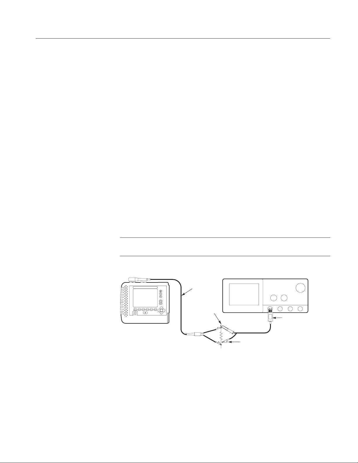
TS200
784 Oscilloscope
Figure 3–3: Verify 2 ns and 10 ns Pulse Widths and Heights
Measure 2 ns and 10 ns Pulses
1. Power on the TS200 and the oscilloscope.
2. Connect a 105 Ω carbon composite resistor across the tip and ring of the
test cable.
TelScout TS200 Access Network Analyzer Service Manual
Test
Cable
105 W
T
R
Probe P6245
Probe
Ground
3–5
Page 46

Performance Verification
3. Connect the P6245 probe to Channel 1 of the oscilloscope.
4. Connect the probe tip to the test cable tip.
5. Connect the probe ground to the test cable ring.
6. Oscilloscope control settings:
Set the vertical scale on Channel 1 to 1V/Div
Set the horizontal scale on Channel 1 to 1 ns/Div
Press the Shift button
Press the Acquire Menu button
Press the Repetitive Signal Off button
Select Off (Real Time Only)
Press the Trigger Menu button
Set Trigger Source to Channel 1
Set the Trigger Slope to positive
Adjust trigger level for approximately 1 volt
Adjust horizontal scale to display the initial portion of the pulse ONLY
Press the Average button and set at 15
Press the Measure button
Select Positive width for measurement one
Select Max Positive for measurement two
Correct
Incorrect
Figure 3–4: Example of Initial Pulse
7. Press
8. Press
9. Press
TDR.
Setup.
Test Type.
10. Highlight Manual TDR.
11. Press
12. Press
13. Use the
H Verify the 2 ns pulse readings are within specifications.
14. Use the
Return to Test.
Pulse.
up and down arrow buttons to select 2 ns.
up and down arrow buttons to select 10 ns.
15. Measure the 10 ns pulse. Adjust the vertical and horizontal scales as
needed.
3–6
H Verify the 10 ns pulse readings are within specifications.
16. Disconnect the cables and remove the P6245 probe.
TelScout TS200 Access Network Analyzer Service Manual
Page 47
Performance Verification
T able 3–1: 2 ns and 10 ns Pulse Specifications
MEASUREMENT PULSE WIDTH PULSE HEIGHT
2 ns 2 ns typical 1.55 V typical
10 ns 12 ns ±20% 4.44 V typical
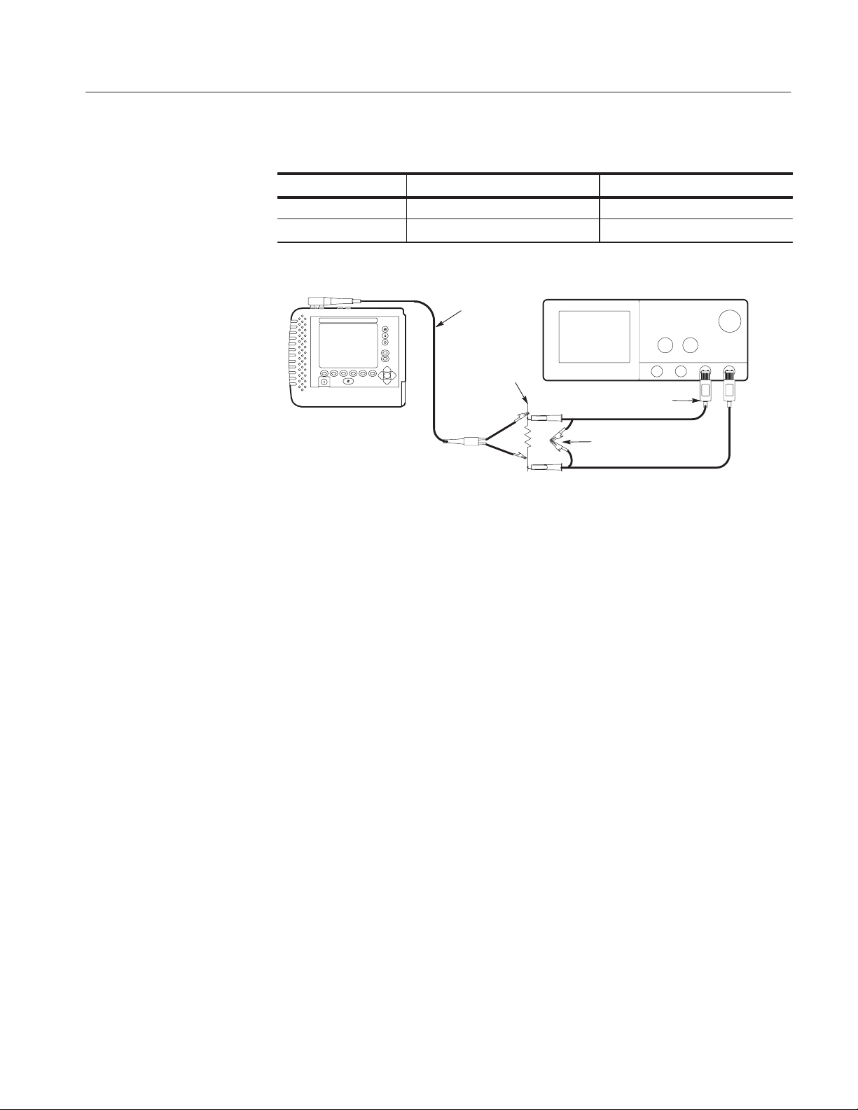
TS200
Test
Cable
105 W
T
R
784 Oscilloscope
P6139A (2)
Probe
Grounds
Figure 3–5: Verify Pulse Widths / Heights ( 75 ns 340 ns and 3400 ns)
Measure the 75, 340 & 3400 ns Pulse
17. Connect a P6139A probe to oscilloscope Channels 3 and 4.
18. Connect the Channel 3 probe tip to the test cable tip.
19. Connect the Channel 4 probe tip to the test cable ring.
20. Connect both probe ground leads together.
21. Connect the probe ground leads to the outer sleeve of the AC adapter.
22. Connect a 105 W resistor as shown in the typical set-up illustration.
23. Oscilloscope control settings:
Turn on Channels 3 and 4 only
Set the vertical scale on Channels 3 and 4 to 2V/Div
Set the horizontal scale on Channels 3 and 4 to 25 ns/Div
Press the Shift button
Press the Acquire Menu button
Press the Repetitive Signal Off button
Select Off (Real Time Only)
Press the Vertical Menu button
Set Channel 3 and 4 input impedance to 1 MΩ
Press the Trigger Menu button
Set Trigger Source to Channel 3
Press the Math Ref button
TelScout TS200 Access Network Analyzer Service Manual
3–7
Page 48

Performance Verification
Select Change Math W/F Definition
Press the Dual Wfm Math button
Set 1st Source to Channel 3
Set 2nd Source to Channel 4
Set Operator to minus (–)
Select OK to Create Math Wfm
Turn off Channels 3 and 4
Press the Math Ref button
Press the Average button and set at 15
Increase the vertical scale of the math waveform to 2.5 V/Div
Pulse
Line Charge
Compensation
Figure 3–6: Example of Peak to Peak Pulse
24. Measure the pulse width at 50% amplitude.
25. Use the
H Verify the 75 ns pulse readings are within specifications.
26. Use the
up and down arrow buttons to select the 75 ns pulse.
up and down arrow button to select and then measure the 340 and
3400 ns pulses.
27. Adjust the vertical scale, horizontal scale, and trigger as required.
H Verify all pulse readings are within specifications.
T able 3–2: 75 ns, 340 ns, 3400 ns Pulse Specifications
PULSE PULSE WIDTH PULSE HEIGHT
75 ns 75 ns typical 8 V typical
340 ns 340 ns (284 ns to 442 ns) 18 V Pk-Pk typical
3400 ns 3400 ns (2550 ns to 3910 ns) 28 V Pk-Pk typical
28. Power off the TS200.
3–8
Check Smoothing
1. Disconnect all attachments from both test cables.
TelScout TS200 Access Network Analyzer Service Manual
Page 49

2. Power on the TS200.
Performance Verification
3. Press the
4. Press the
5. Press the
6. Press the
Reset to Defaults softkey.
TDR softkey.
Setup softkey.
Test Type softkey.
7. Select Manual TDR and verify TEST PAIR is highlighted.
8. Press the
9. Press the
Previous Menu softkey.
More Setups softkey.
10. Verify TDR Distance Units is in FEET.
11. Use the
12. Use the
13. Press the
14. Press the
15. Use the
16. Press the
up and down arrow buttons to highlight Smoothing.
left and right arrow buttons to select the OFF setting.
Return to Test softkey.
Pulse softkey.
up and down arrow buttons to set the pulse width to 10 ns.
Span softkey.
17. Press the
up arrow until approximately 2000 feet is visible on screen.
18. Position the cursor at approximately 2000 feet.
19. Use the
H Verify height of the noise is well within the display window.
20. Press the
21. Press the
22. Use the
23. Use the
24. Press the
H Verify a significant reduction in noise level.
up and down arrow keys to adjust the GAIN to 52 dB.
Setup softkey.
More Setups softkey.
up and down arrow buttons to highlight Smoothing.
left and right arrow buttons to select the 7 setting.
Return to Test softkey.
25. Power off the TS200.
TelScout TS200 Access Network Analyzer Service Manual
3–9
Page 50

Performance Verification
TDR Distance
Measurement Accuracy
TS200
Solder
Lug
to Probe Ground
AC Adapter
AC
Adapter
Plug
to AC Source
Test Cable
T
R
Plug
Channel 1
784 Oscilloscope (Rear)
Coax Delayed
Trigger Output
Cable
BNC Female
Alligator Adapter
Ground (Black)
Trigger (Red)
330 pF
Figure 3–7: Check TDR Distance Accuracy
1. Power on the TS200.
Oscilloscope
Dial
784 Oscilloscope (Front)
Probe
Ground
Probe (10:1)
P6139A
Probe
2. Connect the BNC female adapter to the coax cable.
3. Connect a P6139A probe to Channel 1.
4. Probe, test cable, and coax cable connections:
P6139A probe 330 pf capacitor
TS200 test cable ring 330 pf capacitor
P6139A ground TS200 test cable tip (Probe ground)
Coax cable (red) 330 pf capacitor (opposite end)
Coax cable (black) P6139A ground and TS200 test cable tip
(Probe ground)
AC adapter ground TS200 test cable tip (Probe ground) to
obtain stable pulse on screen
5. Oscilloscope control settings:
Vertical Scale 2 V/div
Horizontal Scale 500 ns/div
Press Trigger Menu button
Press Source button (screen bottom)
Press CH1 button (screen right)
Press Type button until Edge is selected
Press Coupling button (screen bottom)
Press AC button (screen right)
3–10
TelScout TS200 Access Network Analyzer Service Manual
Page 51

Performance Verification
Press Slope button (screen bottom)
Press positive going transition (screen right, top button)
Press Level button
Dial knob to set trigger level to approximately –1V
Press Horizontal Menu button
Press Time Base button (screen bottom)
Press Delayed Only button (screen right)
Use the Horizontal Scale knob to set the Delayed Runs After at 500 ns
Dial knob to set Delay Time at 600 ns
Press Shift
Press Acquire Menu
At screen bottom, press Repetitive Signal Off
Press Off (Real Time Only)
6. Press the
7. Press the
8. Press the
9. Press the
10. Use the
11. Use the
12. Press the
13. Press the
Reset to Defaults softkey.
TDR softkey.
Setup softkey.
More Setups softkey.
up and down arrow buttons to highlight TDR Distance Units.
left and right arrow buttons to change the setting to NANOSECS.
Previous Menu softkey.
Test Type softkey.
14. Select Manual TDR.
15. Press the
H Verify the oscilloscope displays both an incident pulse and a negative-
Return to Test softkey.
going delayed pulse.
16. Press the
Span softkey.
17. Use the up and down arrow buttons to span to 600 ns.
H Verify a positive-going delayed pulse at approximately 300 ns.
18. Place the cursor at the leading edge of the 300 ns pulse.
19. With the Span softkey still highlighted, press the down arrow button until
there is an approximately 80-ns spread across the screen top.
20. Move the cursor to the half-way point on the rising edge of the reflection.
21. Press the
Marker softkey.
22. Use the oscilloscope dial to set the DELAY TIME to 2.600 µs.
TelScout TS200 Access Network Analyzer Service Manual
3–11
Page 52

Performance Verification
23. Verify Span is highlighted.
24. Press the
25. Use the
up arrow button to increase the span to approximately 1.3 µs.
left and right arrow buttons to place the cursor on the rising edge of
the reflection.
26. Press the
down arrow button until there is an approximately 80-ns spread
across the screen top.
27. Move the cursor to the half-way point on the rising edge of the pulse.
H Verify the n distance is 1 µs +/– 0.0013 µs (0.9987 to 1.0013).
28. Set the oscilloscope DELAY TIME to 36.600 µs.
29. Verify that the
30. Press the
31. Use the
Span softkey is highlighted.
up arrow button until there is an approximately 18 µs on screen.
left and right arrow buttons to place the cursor on the rising edge of
the reflection.
32. Press the down arrow button until there is an approximately 80-ns spread
across the screen top.
33. Move the cursor to the half-way point on the rising edge of the pulse.
POTS
H Verify the n distance is 18 µs +/– 0.0183 µs (17.9817 to 18.0183).
34. Power off the TS200.
NOTE. Before performing POTS performance verification testing, disconnect the
AC power source. These tests are to be conducted using TS200 battery power
with the backlight off to minimize interference. POTS testing involves sensitive
measurements; you may want to run the Self Calibration Test frequently.
1. Power on the TS200.
2. Press the
Self Calibration softkey.
3. Follow the on-screen instructions.
H Verify the final screen response reads ‘‘Self Calibration Complete.’’
4. Press the
Done softkey.
3–12
TelScout TS200 Access Network Analyzer Service Manual
Page 53

DC Volts
TS200
Test
Cable
TR
Performance Verification
Reference
Cable
G
High Input
Low Input
9100 Wavetek Calibrator
Figure 3–8: Measure DC V olts
5. Connect the test cable tip and ring to the DC voltage terminals on the
calibrator (tip to high, ring to low).
6. Press the
7. Select
VOM softkey.
DC V olts.
8. Set the calibrator at 5 VDC.
H Verify the TS200 T–R reading is within tolerance.
9. Connect the reference ground to the low input DC Voltage terminal.
10. Connect the test cable tip to the high input terminal of the calibrator.
H Verify the TS200 T–G reading is within tolerance.
11. Connect the test cable ring and reference cable ground to the DC Voltage
terminals (ring to high, ground to low).
H Verify the TS200 R–G reading is within tolerance.
12. Set the calibrator to provide 30 VDC.
H Verify the TS200 R–G reading is within tolerance.
13. Repeat the steps for calibrator settings of 50 VDC and 280 VDC.
H Verify the readings are within tolerance.
AC Volts
14. Connect the TS200 test cable tip and ring leads to the AC voltage terminals
on the calibrator.
TelScout TS200 Access Network Analyzer Service Manual
3–13
Page 54

Performance Verification
15. Press the Main Display softkey.
16. Press the
17. Select
VOM softkey.
AC V olts.
18. Set the calibrator to provide 5 VAC @ 60 Hz.
H Verify the TS200 T–R reading is within tolerance.
19. Now connect the reference cable ground to the low input voltage terminal.
20. Connect the test cable tip to the high input terminal.
H Verify the TS200 T–G reading is within tolerance.
21. Connect the test cable ring and the reference cable ground to the AC
voltage terminals (ring to high, ground to low).
H Verify the TS200 R–G reading is within tolerance.
22. Set the calibrator to provide 30 VAC.
H Verify the TS200 R–G reading is within tolerance.
23. Repeat the steps for calibrator settings of 50 VAC and 280 VAC.
H Verify the readings are within tolerance.
24. Power off the TS200.
Loss and Slope
TS200 Multi-Test Fixture
Terminators
Ω
TS200
Test
Cable
135
Figure 3–9: Loss Slope (Tone Receiver) Performance Check
1. Power on the TS200, the multi-test fixture, and the calibrator.
600
Ω
T
R
Low Input
9100 Wavetek Calibrator
3–14
TelScout TS200 Access Network Analyzer Service Manual
Page 55

Performance Verification
2. Connect the test cable tip to calibrator low and the ring to the calibrator
high output.
3. Set the calibrator output level to 0.7746 Vrms @ 1004 Hz.
NOTE. 0.7746 Vrms = 0 dBm at 600 W
dBm at 600 W = 10 log
Vrms =
600 x 10
dBm –30
10
Vrms
600
2
+ 30
at 600 W
4. Press the Trans. Tests softkey.
5. Press the
H Verify the LOSS LEVEL and FREQUENCY are within specification.
Loss softkey.
6. Set the calibrator output to 77.46 mVrms.
H Verify the LOSS LEVEL is within specification.
7. Set the calibrator output to 13.775 mVrms.
H Verify the LOSS LEVEL is within specification.
8. Set the calibrator output level to 0.7746 Vrms @ 20 Hz.
H Verify the LOSS LEVEL is –3 dB typical.
9. Reset the calibrator output level to 0.5998 Vrms @ 40 kHz.
NOTE. The TS200 uses a 600 W input impedance for all loss and slope measure-
ments. The TS200 assumes the calibrator output impedance is 600 W for
frequencies below 20 kHz and 135 W for frequencies above 20 kHz. To correct
for the loading error above 20 kHz, the actual voltage at the TS200 terminals
should be 1.6327 times the voltage calculated for a 135 W load.
H Verify LOSS LEVEL is within specification.
10. Set the calibrator output to 59.99 mVrms.
H Verify LOSS LEVEL is within specification.
11. Set the calibrator output to 10.67 mVrms.
H Verify the LOSS LEVEL is within specification.
TelScout TS200 Access Network Analyzer Service Manual
3–15
Page 56

Performance Verification
12. Connect a BNC to banana adapter to the SIG OUT terminal on the back
panel of the calibrator. Install 54.5 Ω resistor across SIG OUT terminals on
rear of calibrator using a BNC to banana plug.
NOTE. The 54.5 W resistor, in parallel with the TS200’s 600 W impedance,
provides a 50 W load to the calibrator.
13. Connect the test cable tip and ring to the banana plugs on the BNC adapter.
14. Set up the Wavetek calibrator:
Press the AUX button
Press the Sine Wave button
Highlight DIRECT
15. Set the output volts to 1.6967 V Pk-Pk @ 196 kHz.
NOTE.
Vpk – pk = 2
H Verify the LOSS LEVEL and FREQUENCY readings are within specifi-
Vrms
2
cation.
16. Set the calibrator output volts to 0.16967 V Pk-Pk.
H Verify the LOSS LEVEL reading is within specification.
17. Set the calibrator output volts to .05365 V Pk-Pk.
H Verify the LOSS LEVEL reading is within specification.
18. Disconnect the test cable tip and ring from the calibrator SIG OUT
connector.
19. Connect the TS200 test cable tip to the red 600 W terminator of the test
fixture.
20. Connect the TS200 test cable ring to the calibrator high output.
21. Connect the calibrator low output to the black 600 W terminator.
22. Return the calibrator setting to AC Volts.
3–16
23. Set the calibrator output volts to 0.7746 Vrms @1004 Hz.
H Verify the LOSS LEVEL is –6 dBm ±0.5.
24. Power off the TS200.
TelScout TS200 Access Network Analyzer Service Manual
Page 57

Metallic Noise / Power
Influence
TS200
Test
Cable
TR
Low Input
9100 Wavetek Calibrator
High Input
G
Figure 3–10: Psophometric / C-Message Filter Frequency
Performance Verification
Reference
Cable
NOTE. In this section, noise is measured in dBrn which is power referenced to
1 pw = 10
–12
Watts.
dBrn = dBm +90.
dBrnC is measured with a C-message filter.
dBrnP is measured with a Psophometric filter.
1. Power on the TS200 and the calibrator.
2. Connect the test cable tip and ring to the calibrator high and low input
terminals.
3. Press the
4. Press the
5. Use the
6. Use the
Setup softkey.
More Setups softkey.
up and down arrow buttons to highlight Noise Filter.
left and right arrow buttons to select the Psophometric setting.
T esting Psophometric Filter
7. Press the
8. Press the
Main Display softkey.
Trans. Test softkey.
9. Press the
Noise softkey.
10. Set the calibrator to 7.746 mV @ 800 Hz.
H Verify the NOISE display reads within specification.
TelScout TS200 Access Network Analyzer Service Manual
3–17
Page 58

Performance Verification
H To establish a reference point for psophometric frequency responses,
adjust the calibrator output until the TS200 displays the exact reading of
50 dBrnP.
11. Use the table below and continue to adjust the calibrator for each setting
listed under the Calibrator output setting column.
H Verify the NOISE level readings for each setting are within tolerance.
T able 3–3: Psophometric and C-Message Filter Frequency Responses
Calibrator output setting Psophometric filter setting C–Message filter setting
FREQUENCY NOISE – dBrnP NOISE – dBrnC
100 Hz 9.0 ± 4.0 7.5 ± 4.0
200 Hz 29.0 ± 4.0 24.9 ± 4.0
500 Hz 46.4 ± 3.0 42.3 ± 3.0
800 Hz 50.0 (reference point) 48.7 ± 3.0
1 kHz 51.0 ± 3.0 50.0 (reference point)
2 kHz 47.0 ± 3.0 48.9 ± 3.0
3 kHz 44.4 ± 3.0 47.0 ± 3.0
4 kHz 35.0 ± 5.0 35.4 ± 5.0
5 kHz 14.0 ± 5.0 21.3 ± 5.0
T esting C-Message Filter
12. Press the
13. Press the
Setup softkey.
More Setups softkey.
14. Change the Noise Filter setting to the C-Message setting.
15. Press the
Return to Test softkey.
16. Set the calibrator to 7.746 mV @ 1000 Hz.
H Verify the NOISE display reads within the tolerance.
H To establish a reference point for C-Message frequency responses, adjust
the calibrator output until the TS200 displays the exact reading of 50
dBrnC.
17. Measure the frequency responses for the C-Message filter. Adjust the
calibrator for each setting listed under the Calibrator output setting column.
H Verify the NOISE level readings for each C-Message filter setting are
within the tolerance.
3–18
TelScout TS200 Access Network Analyzer Service Manual
Page 59

60 dB
Attenuator
IN
T
Performance Verification
T
R
Test Cable
T
TS200
High Input
R
OUT
Low Input
T
9100 Wavetek Calibrator
Figure 3–11: Measure Metallic Noise / Power Influence
Measuring Noise and Power Influence
18. Confirm the Noise Filter setting is in C-Message.
19. Connect the test port tip and ring to the test fixture 60 dB Attenuator
output.
20. Connect the calibrator high and low output to the 60 dB input.
NOTE. Do not apply more than 35 Vrms while preforming this test.
21. Set the calibrator to 1 kHz.
22. Use the table below. Adjust the calibrator for each setting listed.
H Verify the NOISE level readings for each setting are within tolerance.
23. Disconnect all connectors from the 60 dB Attenuator.
24. Connect the reference cable ground to the calibrator low output terminal.
25. Connect the test cable tip and ring to the calibrator high output terminal.
26. Set the calibrator for 0.1946 Vrms @ 600 Hz.
H Verify the POWER INFLUENCE reading is 36 dBrnC typically.
27. Reset the calibrator to 60 Hz.
28. Adjust the calibrator for each setting listed in the table below.
H Verify the POWER INFLUENCE readings are within tolerance.
TelScout TS200 Access Network Analyzer Service Manual
3–19
Page 60

Performance Verification
T able 3–4: C–Message Noise and Power Influence Values
Calibrator output volts (rms) NOISE – dBrnC POWER INFLUENCE – dBrnC
7.746 V 50 ± 2.0
2.449 V 40 ± 2.0
.7746 V 30 ± 2.0
.2449 V 20 ± 2.0
.07746 V 10 ± 2.0
194.6 V ––––– 100 ± 2.0
19.46 V ––––– 80 ± 2.0
1.946 V ––––– 60 ± 2.0
.1946 V ––––– 40 ± 2.0
29. Power off the TS200.
Tone Generator
TS200
TS200 Multi-test Fixture
Test
Cable
Terminators
T
R
135
Ω
600
Ω
Keithley Instruments
2000 Multimeter
High Input
Low Input
Figure 3–12: Tone Generator Performance Check
1. Power on the TS200, the multi-test fixture, and the digital multimeter.
2. Set the multimeter impedance at 600 W.
3. Connect the test cable tip and ring to the test fixture 600 W terminators.
4. Connect the multimeter high and low probes to the 600 W terminator.
5. Press the
6. Press the
Trans. Tests softkey.
Tone softkey.
3–20
7. Using the
8. Using the
H Verify the frequency and signal levels are within tolerance.
up and down arrow buttons, highlight 1004 Hz TONE.
left and right arrow buttons, set the LEVEL to 0 dBm.
TelScout TS200 Access Network Analyzer Service Manual
Page 61

Performance Verification
9. At the TS200 TONE display, use the arrow buttons to set the dB levels at
–40, –30, –20, –10, and +10 dBm. (Accuracy is specified for levels
> –25 dBm only.)
H At each level, verify the multimeter signal level readings are within
tolerance.
VOM Ohms
10. At the TS200
TONE display, use the arrow buttons and select the
following: 20 Hz and 20,000 Hz at 0 dBM.
H Verify the multimeter frequency is within tolerance.
H Verify the multimeter level is 0 dBm ± 4 dB.
11. Connect the TS200 and the multimeter leads to the 135 W terminals.
12. Set the multimeter impedance at 135 W.
13. Use the
H Verify the frequency and signal levels are within tolerance.
up and down arrow buttons to select the 40 kHz TONE at 0 dBm.
14. Power off the TS200.
TS200
Reference
Cable
Test Cable
G
T
R
TS200 Multi-Test Fixture
TTTTTTTT
Two Wire Ohms
10 100 1 K 10 K100 K
909 K10 M100 M
RRRRRRRR
Figure 3–13: VOM Ohm Performance Check
1. Power on the TS200 and the multi-test fixture.
2. Connect the test cable tip and ring to the 10 W terminals on the Two Wire
Ohm portion of the multi-test fixture.
3. Press the
4. Press the
H Verify the TS200 T–R reading is within tolerance.
VOM softkey.
Ohms softkey.
5. Connect the test cable tip and the reference cable ground to the 10 W
terminals.
TelScout TS200 Access Network Analyzer Service Manual
3–21
Page 62

Performance Verification
Resistance Fault Locator
H Verify the TS200 T–G reading is within tolerance.
6. Connect the test cable ring and reference cable ground to the 10 Ω
terminals.
H Verify the TS200 R–G reading is within tolerance.
7. Test all resistor terminal sets of the Two Wire Ohm test fixture (100 W,
1 kW, 10 kW, 100 kW, 909 kW, 10 mW and 100 mW).
H Verify the tolerance of the R–G readings for each terminal hook-up.
8. Power off the TS200.
TS200
Reference Cable
Test Cable
R
TS200 Multi-Test Fixture
G
T
R
TTTT
2 & 4 Wire Ohms
RRRR
Event A Event B
Figure 3–14: Resistance Fault Locator Performance Check
1. Power on the TS200 and the multi-test fixture.
2. Perform an instrument self-calibration test to correct for lead resistance. It
is important that the leads make good mechanical contact during the ‘‘short
leads together’’ part of the test.
NOTE. Avoid moving the test leads or disturbing the connections while
self-calibration testing is in process.
3. Connect all TS200 test cable leads to the Event A terminals of the 2 & 4
Wire Ohm section of the multi-test fixture (red to red, black to black, green
to green, and yellow to yellow).
4. Press the
5. Verify
6. Verify
Resistance Fault Loc. softkey.
Short Two Pair is highlighted.
Ohms is highlighted.
3–22
TelScout TS200 Access Network Analyzer Service Manual
Page 63

Performance Verification
DIAMETER
TEMPERATURE
LENGTH
DTF Value STF Value
Red R1
Blk T1
Ylw R2
Grn T2
24
68
AWG
F
ft
Fault Value
Good Pair
DTS Value
Figure 3–15: Sample Display to Verify Readouts
H Verify the display readouts are all within tolerance.
H DTS equals the measured value of R3 + R4 ("0.9% typical).
H DTF equals the measured value of R3 ("0.9% +1 count).
H STF equals the measured value of R4 ("0.9% typical).
Strap
H FAULT equals the measured value of R5 ("0.9% typical).
NOTE. Refer to test fixture calibration data for actual values of R3 through R5.
7. Power off the TS200.
TelScout TS200 Access Network Analyzer Service Manual
3–23
Page 64

Performance Verification
Loop Current
Power Supply
Amp Meter
TS200
Test
Cable
TS200 Multi-Test Fixture
POTS Line Simulator
TTTT
–52.1 Amp Ring Ring
Power
Supply
Meter 62 mA
Loop
RRRR
22 mA
Loop
RT
Figure 3–16: Loop Current Performance Check
1. Power on the TS200, the multi-test fixture, amp meter, and power supply.
2. Connect the test cable tip and ring to the 22 mA Current Loop terminals in
the POTS Line Simulator section of the multi-test fixture (red to red, black
to black).
3. Connect an amp meter to the multi-test fixture Amp Meter terminals.
4. Set the power supply unit to –52.1 volts. Connect the power supply
terminals to the multi-test fixture (red to red, black to black).
5. Press the
6. Press the
H Verify the LOOP CURRENT and amp meter readings are equal " 1%.
VOM softkey.
Loop Current softkey.
7. Connect the test cable tip and ring to the fixtures 62 mA Current Loop
terminals.
H Verify the LOOP CURRENT and amp meter readings are equal " 1%.
8. Power off the TS200.
3–24
TelScout TS200 Access Network Analyzer Service Manual
Page 65

Longitudinal Balance
TS200
Test Cable
T
R
TS200 Multi-Test Fixture
T
T
Longitudinal Balance
R
R
Adj Test
Performance Verification
ON
S1
OFF
ON
S1
OFF
Reference Cable
G
Figure 3–17: Longitudinal Balance Performance Check
1. Power on the TS200 and the multi-test fixture.
2. Connect the test cable tip and ring to the multi-test fixture Longitudinal
Balance Test terminals (red to red, black to black).
3. Connect the reference cable ground to the test fixture (green to green).
4. Press the
5. Press the
Trans. Test softkey.
Long. Balance softkey.
NOTE. Refer to test fixture calibration data for actual values.
H Verify the LONGITUDINAL BALANCE reading is within tolerance
6. Reverse the connections (red to black and black to red).
H Verify the LONGITUDINAL BALANCE reading is within tolerance.
7. Power off the TS200.
Capacitance (Open) Meter
TS200
Reference Cable
Test
Cable
Figure 3–18: Open Capacitance Meter Performance Check
TelScout TS200 Access Network Analyzer Service Manual
TS200 Multi-Test Fixture
G
R
T
TTTT TT
Capacitance
RRRRRR
330 pf 1.2 nf 9.09 nf 100 nf 3.3 uf
300 nf
3–25
Page 66

Performance Verification
1. Power on the TS200 and the multi-test fixture.
2. Perform an instrument self-calibration test to correct for lead capacitance. It
is important that the leads make good mechanical contact during this test.
For best results, lay the test leads on a non-conductive surface.
NOTE. Avoid moving the test leads or disturbing the connections while selfcalibration testing is in process.
3. Connect the test cable tip and ring to the Capacitance section 330 pF
terminals of the multi-test fixture.
4. Press the
H Verify the T–R capacitance is within tolerance.
Open Meter softkey.
5. Connect the test cable tip and the reference cable ground to the 330 pF
terminals.
H Verify the T–G capacitance is within tolerance.
6. Connect the test cable ring and the reference cable ground to the 330 pF
terminals.
H Verify the R–G capacitance is within tolerance.
NOTE. If the instrument fails steps 3, 4, or 5, verify that the self-calibration
testing was performed properly.
7. Test the tip and ring tolerances at the 1.2 nF, 9.09 nF, 100 nF, and 3.3uF
terminals.
H Verify the T–R capacitance is within tolerance.
8. Power off the TS200.
3–26
TelScout TS200 Access Network Analyzer Service Manual
Page 67

Pulse Dialer
Performance Verification
784 Oscilloscope
TS200
P6139A Probe
52.1 V
Power Supply
+
-
Jumper
Installed
TT TT
–52.1
Amp
Power
Meter
Supply
TS200 Multi-Test Fixture
POTS Line Simulator
Ring
62 mA
Loop
T
RRRR
R
Test Cable
Figure 3–19: Pulse Dialer Performance Check
1. Power on the TS200, oscilloscope, multi-test fixture, and the power supply.
2. Make the cable connections as illustrated in the equipment setup.
3. Oscilloscope set-up:
Press the Horizontal menu button
Press the Record Length button
Press the More button
Highlight the 5000 Points block
Press the Time Base button
Select Main
Press the Horizontal Scale button
Use the Horizontal Scale dial to set at 200 ms
Use the Vertical Scale dial to set at 20 V/div
Press the Trigger Menu Button,
Set Trigger Level on screen to 33-35 V
4. Press the
5. Press the
6. Press the
Trans. Test softkey.
Select Phone # softkey.
Enter Phone # softkey.
7. Enter a phone number.
8. Press the
Dial Type softkey.
TelScout TS200 Access Network Analyzer Service Manual
3–27
Page 68

Performance Verification
9. Use the left and right arrow buttons to highlight Pulse on-screen.
10. Return to the oscilloscope for further setups.
Press the Shift button
Press the Single Trig button
11. Observe the Trigger position reading. There will be a momentary flash of
PrTrig. After the flash when TRIG appears, press the
Send softkey.
12. Press the oscilloscope ZOOM button.
13. Adjust the Horizontal Position and Horizontal Scale controls as needed.
14. Measure the time between dialing frequency.
H Verify the reading is between 100 ms and 125 ms.
15. Measure the Break Time.
H Verify the North American reading is 53 ms to 80 ms (UK, 60 – 70 ms).
16. Measure the Inter-digit Pause.
DTMF Dialer
H Verify the reading is 680 ms to 2 seconds (North American and the UK).
Inter-digit
Pause
–50 V
Off Hook
Break Time
Digit 4 Digit 3
Dialing
Frequency
Figure 3–20: T ypical Waveform for Dialer Performance Check
17. Power off the TS200.
3–28
1. Refer to the DTMF typical setup and connect test equipment.
2. Power on the TS200, computer, DTMF converter, and the multi-test
fixture.
TelScout TS200 Access Network Analyzer Service Manual
Page 69

52.1 V
Power Supply
+
-
Test Cable
RT
TS200 Multi-Test Fixture
POTS Line Simulator
TT TT
–52.1
Power
Supply
Amp
Meter
22 mA
Jumper Installed
RRRR
Ring
Loop
TS200
G
R
Telephone
Cable
Performance Verification
Reference
Cable
Computer
RS232
DTMF<–>ASCII Converter
(Back)
12345678
Figure 3–21: DTMF Dialer Performance Check
NOTE. The DTMF and computer communications set-ups: Baud rate = 19200,
Data bits = 7, Stop bits = 2, Parity = None, Flow control = Xon/Xoff.
3. Press the
4. Press the
5. If no phone number is displayed, press the
H Use the DIAMOND button or the Insert Char softkey to enter the name.
H Press the Done softkey.
H Press the Enter Phone # softkey.
H Use the arrow buttons and front-panel softkeys to select numbers.
6. Press the
7. Press the
8. Use the
Trans. Tests softkey.
Select Phone # softkey.
Enter Name softkey.
DIAMOND button to return to the Select Phone# display.
Dial Type softkey.
left and right arrow buttons to select DTMF.
NOTE. Before starting a terminal session on the computer, be sure the terminal
settings match the DTMF box settings.
TelScout TS200 Access Network Analyzer Service Manual
3–29
Page 70
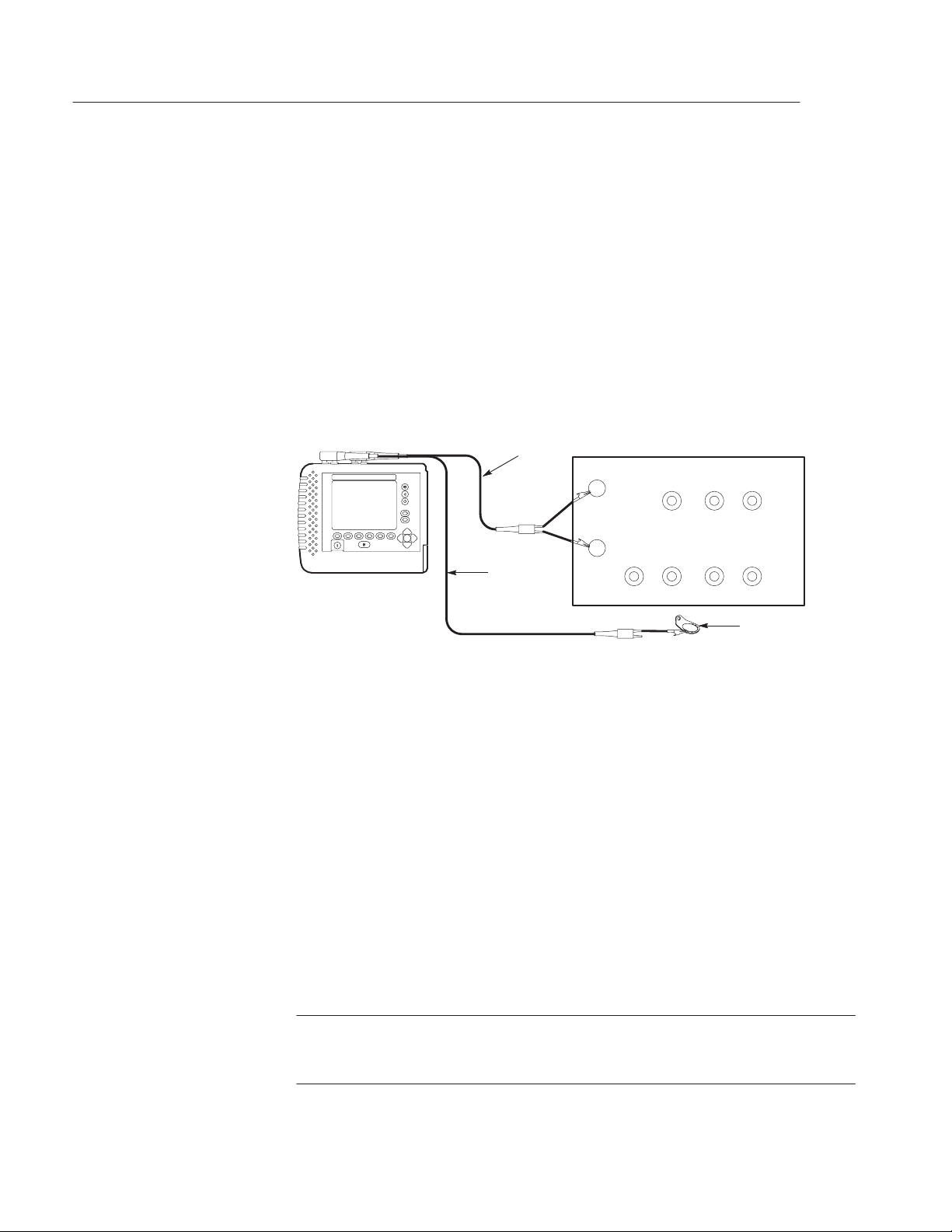
Performance Verification
9. At the computer keyboard, press the Ctrl-A key.
Load Coils, 66 mH / 88 mH
10. Press the
Send softkey and verify the computer displays the correct phone
number.
11. Power off the TS200.
1. Power on the TS200 and the multi-test fixture.
2. Connect the test port tip to the black 66 mH Load Coils terminal of the
multi-test fixture.
TS200
Test
Cable
T
R
Reference
Cable
TS200 Multi-Test Fixture
66 mH Load Coils
T
#2 #3 #4
R
G
#6 #7 #8#5
ON
OFF
ON
OFF
Multi-Test
Fixture Lug
Figure 3–22: Load Coil Performance Checks
3. Connect the test port ring to the red terminal.
4. Connect the reference port ground to the lug at the bottom of the fixture.
5. Flip all test fixture toggle switches to the OFF position.
6. Press the
7. Press the
VOM softkey.
Counts Load softkey and verify there are at least 7 LOAD
COILS FOUND.
8. Connect the test port tip and ring to the 88 mH Load Coil terminals.
9. Press the
Counts Load softkey and verify there are at least 6 LOAD
COILS FOUND.
NOTE. Successful completion of this test with the 88 mH fixture, along with the
Loss and Slope test and Tone Generator test, is sufficient for verifying correct
operation of the Load Coil TestWizard function.
3–30
TelScout TS200 Access Network Analyzer Service Manual
Page 71

Performance Verification
TS200 Test Record
TS200 Serial Number: Certificate Number:
Date of Calibration: Technician:
* Minimum and maximum values are nominal values. Adjust to correspond with the TS200 multi-test fixture
calibration values (CV).
T able 3–5: TelScout TS200 Test Record
TS200 Performance Parameter Minimum Incoming Outgoing Maximum
TDR Pulse Width
10 ns Width 9.6 ns 14.4 ns
340 ns Width 289 ns 442 ns
3400 ns Width 2550 ns 3910 ns
TDR Distance Accuracy
1 ms 0.9987 ms 1.0013 ms
18 ms 17.9817 ms 18.0183 ms
POTS DC Volts
5 VDC Ring to Gnd 4.45 V 5.55 V
30 VDC Ring to Gnd 29.2 V 30.8 V
50 VDC Ring to Gnd 49.0 V 51.0 V
280 VDC Ring to Gnd 276.7 V 283.3 V
POTS AC Volts
5 VAC Ring to Gnd 4.45 V 5.55 V
30 VAC Ring to Gnd 29.2 V 30.8 V
50 VAC Ring to Gnd 49.0 V 51.0 V
280 VAC Ring to Gnd 276.7 V 283.3 V
TelScout TS200 Access Network Analyzer Service Manual
3–31
Page 72

Performance Verification
T able 3–5: TelScout TS200 Test Record (cont.)
TS200 Performance Parameter MaximumOutgoingIncomingMinimum
Loss and Slope
Calibrator @ 0.0 dBm (0.7746 Vrms) @ 1004 Hz
Loss –0.5 dBm 0.5 dBm
Frequency 1002 Hz 1006 Hz
Calibrator @ –20 dBm (77.46 mVrms) @ 1004 Hz
Loss –20.5 dBm –19.5 dBm
Calibrator @ –35 dBm (13.775 mVrms) @ 1004 Hz
Loss –35.5 dBm –34.5 dBm
Calibrator @ 0.0 dBm (0.5998 Vrms) @ 40 kHz
Loss –2.0 dBm 2.0 dBm
Frequency 39998 Hz 40002 Hz
Calibrator @ –20 dBm (59.99 mVrms) @ 40 kHz
Loss –22.0 dBm –18.0 dBm
Calibrator @ –35 dBm (10.67 mVrms) @ 40 kHz
Loss –37.0 dBm –33.0 dBm
Calibrator @ 0.0 dBm (1.6967 V Pk-Pk) @ 196 kHz
Loss –4.0 dBm 4.0 dBm
Frequency 195.998 kHz 196.002 kHz
Calibrator @ –20 dBm (0.16967 V Pk-Pk) @ 196 kHz
Loss –24.0 dBm –16.0 dBm
Calibrator @ –30 dBm (0.05365 V Pk-Pk) @ 196 kHz
Loss –34.0 dBm –26.0 dBm
Calibrator @ 0.0 dBm (0.7746 Vrms) @ 1004 Hz
Loss (600 Ω in series) –6.5 dBm –5.5 dBm
POTS Metallic Noise/Power Influence – Psophometric filter
Calibrator set to 7.746 mVAC
@ 800 Hz 48.0 dBrnP 52.0 dBrnP
Reset Calibrator reading to 50.0 dBrnP
@ 100 Hz 5.0 dBrnP 13.0 dBrnP
@ 200 Hz 25.0 dBrnP 33.0 dBrnP
@ 500 Hz 43.4 dBrnP 49.4 dBrnP
@ 1 kHz 48.0 dBrnP 54.0 dBrnP
@ 2 kHz 44.0 dBrnP 50.0 dBrnP
3–32
TelScout TS200 Access Network Analyzer Service Manual
Page 73

T able 3–5: TelScout TS200 Test Record (cont.)
TS200 Performance Parameter MaximumOutgoingIncomingMinimum
@ 3 kHz 41.4 dBrnP 47.4 dBrnP
@ 4 kHz 30.0 dBrnP 40.0 dBrnP
@ 5 kHz 9.0 dBrnP 19.0 dBrnP
POTS Metallic Noise/Power Influence – C-Message filter
Calibrator set to 7.746 mVAC
@ 1000 Hz 48 dBrnC 52 dBrnC
Reset Calibrator reading to 50.0 dBrnC
@ 100 Hz 3.5 dBrnC 11.5 dBrnC
@ 200 Hz 20.9 dBrnC 28.9 dBrnC
@ 500 Hz 39.3 dBrnC 45.3 dBrnC
@ 800 Hz 45.7 dBrnC 51.7 dBrnC
@ 2 kHz 45.9 dBrnC 51.9 dBrnC
@ 3 kHz 44.0 dBrnC 50.0 dBrnC
@ 4 kHz 30.4 dBrnC 40.4 dBrnC
@ 5 kHz 16.3 dBrnC 26.3 dBrnC
Performance Verification
NOISE (with 60 dB attenuator @ 1000 Hz)
7.746 Vrms 48.0 dBrnC 52.0 dBrnC
2.449 Vrms 38.0 dBrnC 42.0 dBrnC
0.7746 Vrms 28.0 dBrnC 32.0 dBrnC
0.2449 Vrms 18.0 dBrnC 22.0 dBrnC
0.07746 Vrms 8.0 dBrnC 12.0 dBrnC
Power Influence
194.6 Vrms @ 60 Hz 98.0 dBrnC 102.0 dBrnC
19.46 Vrms @ 60 Hz 78.0 dBrnC 82.0 dBrnC
1.946 Vrms @ 60 Hz 58.0 dBrnC 62.0 dBrnC
0.1946 Vrms @ 60 Hz 38.0 dBrnC 42.0 dBrnC
POTS Tone Generator @ 600 W
1004 Hz @ 0.0 dBm Level –0.5 dBm 0.5 dBm
Frequency 1002 Hz 1006 Hz
1004 Hz @ –20.0 dBm Level –20.5 dBm –19.5 dBm
TelScout TS200 Access Network Analyzer Service Manual
3–33
Page 74

Performance Verification
T able 3–5: TelScout TS200 Test Record (cont.)
TS200 Performance Parameter MaximumOutgoingIncomingMinimum
1004 Hz @ –10.0 dBm Level –10.5 dBm –9.5 dBm
1004 Hz @ +10.0 dBm Level 9.5 dBm 10.5 dBm
20 kHz @ 0.0 dBm Frequency 19.998 kHz 20.002 kHz
POTS VOM W*
10 W Tip to Ring CV–1.2 W CV+1.2 W
Tip to Gnd
Ring to Gnd
100 W Ring to Gnd CV–2.0 W CV+2.0 W
1 kW Ring to Gnd CV–0.011 kW CV+0.016 kW
10 kW Ring to Gnd CV–0.1 kW CV+0.1 kW
100 kW Ring to Gnd CV–0.91 kW CV+1.1 kW
CV–1.2 W CV+1.2 W
CV–1.2 W CV+1.2 W
909 kW Ring to Gnd CV–9.2 kW CV+9.2 kW
10 MW Ring to Gnd CV–0.7 MW CV+0.7 MW
100 MW Ring to Gnd CV–6.1 MW CV+6.1 MW
POTS Resistance Fault Locator *
DTF
POTS Loop Current
22 mA 21.78 mA 22.22 mA
62 mA 61.38 mA 62.62 mA
POTS Longitudinal Balance *
Reading #1 CV–2.0 dB CV+2.0 dB
Reading #2 (reversed) CV–2.0 dB CV+2.0 dB
Capacitance *
0.33 nF Tip to Ring CV–0.06 nF CV+0.06 nF
Tip to Gnd CV–0.06 nF CV+0.06 nF
Ring to Gnd CV–0.06 nF CV+0.06 nF
1.2 nF Tip to Ring CV–0.07 nF CV+0.07 nF
9.09 nF Tip to Ring CV–0.15 nF CV+0.15 nF
CV–9.1 W CV+9.1 W
3–34
TelScout TS200 Access Network Analyzer Service Manual
Page 75

Performance Verification
T able 3–5: TelScout TS200 Test Record (cont.)
TS200 Performance Parameter MaximumOutgoingIncomingMinimum
0.1 mF Tip to Ring CV–0.01 mF CV+0.01 mF
3.3 mF Tip to Ring CV–0.04 mF CV+0.04 mF
POTS Pulse Dialer
Time between pulses 100 ms 125 ms
Break time 53 ms 80 ms
European settings 60 ms 70 ms
Inter-digit pause 680 ms 2 sec
POTS Load Coil Counter
66 mH 7 loads
88 mH 6 loads
TelScout TS200 Access Network Analyzer Service Manual
3–35
Page 76

Performance Verification
3–36
TelScout TS200 Access Network Analyzer Service Manual
Page 77

Maintenance
This chapter contains information you need to do periodic and corrective
maintenance on the TelScout TS200. These maintenance instructions are for
qualified service personnel only. Prior to performing any maintenance on this
instrument, read the General Safety Summary and the Preface at the beginning of
this manual. If you have not used the TS200 before, refer to the TelScout TS200
User Manual.
CAUTION. These servicing instructions are for use by qualified personnel only. To
avoid electric shock, do not perform any servicing other than that contained in
this manual unless you are qualified to do so.
CAUTION. Static discharge can damage any semiconductor component in this
instrument.
When performing any service that requires internal access to the instrument, take
the following precautions to avoid damaging internal modules and their
components with electrostatic discharge (ESD):
H Minimize handling of static-sensitive modules.
H Transport and store static-sensitive modules in static-protected containers.
Label any package that contains static-sensitive modules.
H Discharge the static voltage from your body by wearing a grounded wrist strap
while handling these modules. Service the modules only at a static-free
workstation.
H Do not allow anything capable of generating or holding a static charge on the
workstation surface.
H Handle the circuit board by the edges whenever possible. Avoid touching
the board surface and components to prevent contamination.
H Do not slide the modules over any surface.
H A void handling the modules in areas that have carpeted floors or work surfaces
capable of generating static charges.
TelScout TS200 Access Network Analyzer Service Manual
4–1
Page 78

Maintenance
Inspection and Cleaning
Exterior Inspection
The TelScout TS200’s enclosure minimizes dust accumulation inside the
instrument. Never operate the MTDR without the covers properly installed.
When storing or transporting the instrument, it is a good idea to keep it in the
soft carry case to protect it from dust and accidental damage.
Inspect and clean your TelScout TS200 as often as operating conditions require.
If used indoors, this might be once every 1000 hours of use. If used outdoors,
this might be after each use, depending on field conditions, but the instrument
should be inspected and cleaned after no more than 500 hours of use. Dirt acts as
a thermal insulator, which could cause overheating and component breakdown. It
also provides an electrical conduction path that could cause instrument failure,
especially under high-humidity conditions.
H Inspect the exterior of the TS200 for wear, missing parts, or cracks in the
enclosure. Replace any defective parts.
Exterior Cleaning
Interior Inspection
H Inspect all connectors for cracked insulation, broken shells, deformed
contacts, or dirt in the connectors. Clean or replace as necessary.
H Inspect test cables for bent or broken plugs/clips or frayed/cut insulation.
Replace as necessary.
CAUTION. To avoid the possibility of getting water in the instrument, use only
enough liquid to dampen the cloth. Do not use abrasive cleaners or harsh
chemicals (e.g., alcohol, acetone) as damage to the enclosure might result.
H Remove dust from the outside of the instrument by wiping with a lint-free
cloth or small brush. Use the brush to remove dust from the connectors.
H Clean the remaining dirt with a lint-free cloth, dampened in a general-purpose
mild-detergent-and-water solution.
To gain access to the inside of the TS200 for inspection and cleaning, refer to the
Removal and Reinstallation Procedures given later in this chapter.
4–2
H Inspect the circuit board for loose, broken, or corroded solder connections and
burned, broken, or cracked circuit plating. Replace the circuit board if these
conditions exist.
TelScout TS200 Access Network Analyzer Service Manual
Page 79

Interior Cleaning
Maintenance
H Inspect resistors for burns, cracks, blisters, or breaks. Replace the circuit board
if these conditions exist.
H Inspect capacitors for damaged or leaking cases, or corroded solder on leads.
Replace the circuit board if these conditions exist.
H Inspect all solder joints for cold or rosin joints. Replace the circuit board if
these conditions exist.
H Inspect all semiconductor devices for loose socket connections or bent/dam-
aged leads. If the device is socketed, attempt to reseat the device properly . If
device is soldered on the board, replace the circuit board.
H Inspect wiring and cables for loose plugs or connectors and burned, broken,
or frayed wiring. Reseat connector or replace wiring as necessary.
H Inspect interior of enclosure for deformation, cracking, or damaged hardware.
Replace as necessary.
Software Downloading
H Blow any dust found in the interior of the instrument out using dry, low
pressure (approximately x. 9psi), de-ionized air.
H Remove any remaining dust using a lint-free cloth dampened in de-ionized
water. Lint-free swabs are useful for cleaning narrow spaces and on the circuit
board.
To download software to the TS200, an IBM compatible computer running
Windows 95 or Windows 98 needs to be used. The process takes approximately
20 minutes. In the event of a failure that cannot be resolved, call 1-800-833-9200
for assistance.
The TS200 must be connected to a PC using a PC/AT serial (Com1) port with
Tektronix part numbered optional accessory (9-pin D-connector) (Tektronix part
number 012-1380-00) or equivalent serial null-modem cable conforming to the
following pinout chart:
T able 4–1: Serial Cable Pinout Chart
Female 9-PIN Female 9-PIN
2 3
3 2
4 6
5 5
TelScout TS200 Access Network Analyzer Service Manual
4–3
Page 80

Maintenance
T able 4–1: Serial Cable Pinout Chart (cont.)
Female 9-PIN Female 9-PIN
6 4
7 1, 8
8 7
9 –––
After connecting the TS200 to your PC, follow the steps described below:
1. While pressing the (
instrument.
2. Insert the release disk into the PC’s floppy disk drive.
3. Open a DOS window and from the DOS prompt type “A:INSTALL.”
4. After the installation is complete, enter LDTS200 TS101L?.SYS, where
‘‘?’’ refers to the language option.
The LDTS200 program uses COM1 by default. If the TS200 is attached to a port
other than COM1, type ‘‘LDTS200’’ and press enter. The program will prompt
you for the COM port and the filename.
Functional Testing
Follow the Performance Verification in Chapter 3 to test the TS200 for
functionality. If the TS200 does not meet all performance specifications, it must
be returned to Tektronix for repair and/or calibration.
Removal / Installation Procedures
The TDR circuit board memory contains all calibration constants and instrument
configuration information. If either circuit board is replaced, a complete
calibration must be performed. Additionally, if the TDR board is replaced, the
instrument configuration must be reset.
◆) button, press the power button to power on the
4–4
External software is required for both calibration and configuration. The TS200
must be returned to your Tektronix Service Center for both calibration and
configuration.
TelScout TS200 Access Network Analyzer Service Manual
Page 81

Required Equipment
Maintenance
H Static-free workstation
H Small pair of sidecuts (dikes)
H Phillips screwdriver, medium point or Pozidrive screwdriver, PZI
H Torx T10 screwdriver
H Torx T15 screwdriver
H Nut drivers, 1/4 inch and 3/16 inch
H Needle-nose plier
H End wrench, 5/16
CAUTION. To prevent possible damage to the front panel or display, be sure the
work surface is clear of debris (e.g., screws, wire clippings, etc.) prior to laying
the top case-half face down. One way to do this would be to place a clean soft
cloth on the flat work surface.
Disassembly Procedures
NOTE. Maintenance illustrations demonstrating cable attachment/placements are
often represented by simple line drawings shaded in gray. Refer to the cable
section of the replaceable parts chapter for a full description and technical
drawing of each cable.
1. Place the TS200 on a static-free work station. To remove the battery pack, use
a flat screwdriver to back out four 6–32 x 0.50 captive screws. Disconnect the
battery connector from the DC power jack cable. Slide the battery pack out. The
Tektronix product label for the TS200 may be removed by lifting from any
corner and peeling back carefully.
TelScout TS200 Access Network Analyzer Service Manual
4–5
Page 82

Maintenance
Â
TS200 label
Battery pack
Captive screws
DC power
jack cable
6-32 x 0.50 (4)
Figure 4–1: Battery Removal
2. T urn the TS200 display-side down. Use a Pozidrive screwdriver to remove eight
6–32 x 1.75 screws attaching the case halves. Set the bottom case-half aside.
Gently lift the eight inch long o-ring gasket from the edge of the top case-half.
Screws (8)
Bottom case-half
Top case-half
6-32 x 1.75
O-ring gasket
Figure 4–2: Opening the TS200 Instrument
3. Disconnect the speaker cable assembly , ribbon data cable, and tip and ring cable
assemblies attached to circuit board A1.
4–6
TelScout TS200 Access Network Analyzer Service Manual
Page 83

Maintenance
Circuit board A1
Speaker cable
assembly
Data cable
Tip & ring cable
Figure 4–3: Disconnecting Circuit Board Assembly A1 Cable Attachments
4. Use a Pozidrive screwdriver to remove six 4–40 x 0.312 screw assemblies from
the hex spacer posts between circuit boards A1 and A2. Lift circuit board A1
and place on a static-free mat.
Circuit board A1
Screws (6)
4-40 x 0.312
Circuit board A2
Top case-half
Spacer posts (6)
Figure 4–4: Removing Circuit Board Assembly A1
5. Disconnect the LCD inverter cable, the DC power/battery cable assembly, and
the flex circuit cable from circuit board A2. Position the unconnected ends of
all cables clear of the A2 board. Disconnect and remove the data cable and the
tip & ring cable.
TelScout TS200 Access Network Analyzer Service Manual
4–7
Page 84

Maintenance
LCD inverter
cable
Data cable
Circuit board A2
DC power/battery
cable
Tip & ring cable
Flex circuit
cable
Figure 4–5: Disconnecting Circuit Board Assembly A2 Cables
6. Before removing circuit board A2, disconnect the remaining four cables
including the serial interface ribbon cable, the LCD temperature sensor cable,
the FPC cable, and the twisted pair cable.
LCD temperature
sensor cable
Circuit board A2
4–8
FPC cable
Serial interface
ribbon cable
Twisted pair cable
Figure 4–6: Preparing to Remove Circuit Board Assembly A2
7. Use a 1/4 inch hex socket driver to remove five 4–40 x 0.751 hex spacer posts.
Use a 3/16 hex socket driver to remove one smaller hex spacer post. Lift circuit
board A2 and place on a static-free work station.
TelScout TS200 Access Network Analyzer Service Manual
Page 85

Spacer posts (5)
Spacer post (1)
Figure 4–7: Removing Circuit Board Assembly A2
Maintenance
Circuit board A2
8. Remove the DC power jack cable assembly. Carefully slide the external power
input connector up and out of the top case-half. Next, release the DC power jack
cable from three nylon cable clamps. Use a Pozidrive screwdriver to remove
three 4–40 x 0.312 screws which secure the clamps to the support plate.
NOTE. The DC power jack cable assembly includes an o-ring on the connector.
Be careful and not misplace during disassembly.
Cable clamps (3)
Support plate
Screws (3)
4-40 x 0.312
DC power jack
cable
External power
input connector
Figure 4–8: Removing More Cable Assemblies
TelScout TS200 Access Network Analyzer Service Manual
4–9
Page 86

Maintenance
9. The speaker cable assembly is attached to the top case-half by four 6–32 screws
and four 6–32 x 0.312 nut assemblies. One of the 6–32 screws attaches the dust
cap assembly . Use a 5/16 end wrench and a Torx T15 screwdriver to remove this
hardware. The speaker, grill gaskets, and the dust cap are now free. The speaker
portion with the cable assembly is ready for removal.
Speaker
cable assembly
Dust cap
Screws (4)
6-32 x 0.625
Nuts (4)
6-32 x 0.312
Figure 4–9: Removing the Speaker Cable Assembly
10. Use a needle-nose plier to grasp each quick disconnect terminal on the twisted
pair cable assembly and remove from the four safety jack lugs. Remove the
twisted pair cable assembly.
11. Use a Pozidrive screwdriver to remove one 4–40 x 0.312 screw assembly.
4–10
12. The inverter board jumper cable is attached to the LCD display assembly under
the support plate. Disconnect this cable. The FPC cable is secured to the support
plate with adhesive tape. Gently lift from support plate and slip out through the
ferrite bead which is secured to the support plate.
TelScout TS200 Access Network Analyzer Service Manual
Page 87

Maintenance
Needle-nose
plier
Jumper cable
Safety jacks (4)
Twisted pair
cable assembly
Support plate
FPC cable
Figure 4–10: Preparing to Remove the Support Plate Assembly
13. Use a Pozidrive screwdriver to remove the remaining four 4–40 x 0.312 screw
assemblies which attach the support plate to the top case-half. Lift the support
plate and set on a static-free mat. The inverter circuit board A4 is part of this
assembly.
Screws (4)
4-40 x 0.312
Support plate
Circuit board A4
Top case-half
Figure 4–11: Removing the Support Plate Assembly
14. The support plate with the DC–AC converter board A3 is ready for disassembly .
Remove the LCD temperature sensor cable from the support plate by clipping
the zip tie with a small pair of sidecuts.
15. Use a Pozidrive screwdriver to remove the two 4–40 x 0.312 screw assemblies
which attach the circuit board A3 and insulate to the support plate. Remove two
4-40 nut assemblies to free the brass inverter shield attached to the support plate.
TelScout TS200 Access Network Analyzer Service Manual
4–11
Page 88

Maintenance
16. Disconnect both the LCD cable and the jumper cable from the inverter board.
LCD cable
Inverter board
insulate
Screws (2)
4-40 x 0.312
Jumper cable
Brass inverter
shield
LCD temperature
sensor cable
DC–AC converter board A3
Support plate
Zip tie
Figure 4–12: Disassemble the Support Plate; Remove DC–AC Converter Board A3
17. Removing the LCD display module is simple; it has no attaching hardware. It
is indexed by the LCD plate below and the support plate on top. Be careful to
lift around the safety jack terminals. Disconnect the FPC cable from the LCD
display module A4 assembly.
LCD assembly
A4
Safety jack
terminals
FPC cable
LCD plate
assembly
Figure 4–13: Removing the LCD Display Module A4 Assembly
4–12
18. Lift the LCD plate assembly off the top case-half index tabs. Gently lift the flex
circuit off the same index tabs.
TelScout TS200 Access Network Analyzer Service Manual
Page 89

Maintenance
NOTE. Be careful to avoid contact with exposed traces on the bottom side of the
flex circuit.
LCD plate
assembly
Flex circuit
Index slots
Index tabs
Figure 4–14: Removing the LCD Plate Assembly and Flex Circuit
19. Remove the elastomeric keypad by simply lifting it off the top case-half index
tabs.
NOTE. Avoid contact with the conductive pads on the elastomeric keypad.
20. Remove the serial interface ribbon cable assembly from the top case-half. Use
a Torx T10 screwdriver to remove two 4–40 x 0.375 screws.
Serial interface
Top case-half
Screws (2)
4-40 x 0.375
ribbon cable
Elastomeric
keypad
Index tabs
Figure 4–15: Disassembling the T op Case–half
TelScout TS200 Access Network Analyzer Service Manual
4–13
Page 90

Maintenance
21. If it becomes necessary to replace the TS200 top case-half, the display window
must be replaced also. Install by simply removing the adhesive covering from
the display window and gently pressing down into the top case-half. Snug the
window into the corner indicated below.
Window adhesive
Use this corner
for display window
Figure 4–16: Installing the Display Window
22. Disassembly of the TS200 is now complete.
Reassembly
To reassemble the TS200, reverse the disassembly procedures.
Longitudinal Balance Adjustment
1. Press the TS200 Long. Balance softkey.
Display window
5.910 x 4.530
alignment
4–14
2. Connect the test port tip and ring to the longitudinal balance ‘‘Adjustment’’
terminals on the Longitudinal Balance section of the TS200 Multi-Test
Fixture.
3. Set the longitudinal balance switches on the multi-test fixture to the OFF
position.
4. Access the POTS board through the shield access hole. Adjust R1066 for
maximum reading. The reading should be 80 dB or greater (see
Figure 4–17).
NOTE. By reversing the tip and ring connectors, you can verify that the TS200 is
not being miscalculated and there is not an unbalance in the test fixture.
TelScout TS200 Access Network Analyzer Service Manual
Page 91

Brass shield
Maintenance
Longitudinal balance
Troubleshooting
adjustment
POTS circuit board
(front)
Figure 4–17: POTS Longitudinal Balance Adjustment
5. Connect the test port tip and ring to the longitudinal balance ‘‘Test’’
terminals on the Longitudinal Balance section of the multi-test fixture.
H Verify the reading is approximately 62 dB.
6. Reverse the tip and ring connections at the multi-test fixture.
H Verify the reading is approximately 62 dB.
Required Equipment
Setup for Troubleshooting
Troubleshooting
1. TS200 WILL NOT POWER ON, or WILL NOT STAY POWERED ON, or BATTERY LIFE IS TOO
H Static-free workstation
H Digital multimeter
H Perform preliminary disassembly.
H Leave all electrical connections intact.
H Connect AC adapter/charger and plug into known good AC source.
SHORT, or BATTERY WILL NOT CHARGE.
Step 1. Measure the voltage at the External DC adapter connection. The voltage
should be 18 to 25 VDC under all normal charging or operating conditions.
♦ If the External DC adapter voltage is above 25 V, replace the external
adapter.
TelScout TS200 Access Network Analyzer Service Manual
4–15
Page 92

Maintenance
♦ If the External DC adapter voltage is below 18 V, check for excess current
consumption by the TS200.
♦ If current consumption is not excessive, replace the external adapter.
a) Verify the TS200 does not require excessive current. Connect the External DC
power adapter and disconnect the battery. Typical current requirements with
24 V power from the external adapter are:
Instrument off, battery disconnected 10 mA
Instrument off, battery charging 600 mA
TDR only, main screen, backlight off 250 mA
TDR only, main screen, backlight normal 300 mA
TDR only, main screen, bright backlight 360 mA
Combo unit, main screen, backlight normal 350 mA
Combo unit, DCV screen, backlight normal 430 mA
♦ If the current requirement is excessive on a combo unit, unplug POTS
connector J1001 to see if the POTS board is causing the excessive current
consumption.
NOTE. The battery will not charge or will stop charging if the battery
voltage is too high (above approximately 16.2V) or too low (below
approximately 9 V).
If the battery temperature is too high, the charging circuit will
hold off charging until the battery temperature drops below approximately 40° C. Charging will terminate if the battery temperature rises
above approximately 50° C, if the battery temperature increases rapidly,
or if the battery voltage decreases.
The fully discharged battery will take approximately four hours
to charge. A battery is considered discharged if the TS200 shuts off
automatically due to low battery voltage.
Charging systems for NiMH batteries are more complex than for
lead acid or NiCad batteries. If a spare battery and spare external
adapter are available, it is useful to verify the problems below with the
substitute parts.
Battery capacity drops as ambient temperature increases or
decreases from room temperature. This is a normal battery characteristic for both charging and discharging. As an example, if the battery is
charged at 40° C, it could have 25% lower charge capacity. For best
results, charge the battery at room temperature with the instrument
power off.
Battery self-discharge is assumed to be about 2% per day. It may
be higher immediately following a charge.
4–16
TelScout TS200 Access Network Analyzer Service Manual
Page 93

Maintenance
b) When the instrument is off, current from the external adapter should be approxi-
mately 600 mA when the battery voltage is approximately 12 V. The current will
be lower when battery voltage is low and higher when battery voltage is high.
Charging should start within five seconds after an external adapter is connected
to the TS200 if voltages and temperatures are correct.
♦ If the charge current is too high, replace the TDR board.
c) When the charge current is too low , check the battery voltage while charging (pins
1 and 6 of the 6-pin battery connector).
♦ If the battery voltage is below 9.1 V for more than a few minutes while
charging, replace the battery.
♦ If the battery voltage is between 9.1 V and 15 V and charge current is low,
replace the TDR board.
♦ If battery voltage is above 15 V at room temperature, the battery may
have a full charge, or it may be defective.
♦ If the voltages and currents are normal, but the battery life is short, the
battery should be replaced.
2. BATTERY CAP ACITY GAUGE IS INACCURATE.
NOTE. The battery capacity gauge automatically recalibrates when the battery goes
through a complete charge/discharge/charge cycle. With normal operation, the
battery is often charged without having a full discharge. Over time, the battery
capacity gauge will become less accurate until another complete charge/discharge/
charge cycle occurs.
The fuel gauge for the battery is mounted inside the battery pack. The fuel
gauge is designed to work correctly when the battery is removed and reinstalled.
The current sense for charge and discharge is mounted in the TS200. Best fuelgauge accuracy is obtained if the battery is both charged and used in the same
instrument.
Step 1. Recalibrate the battery fuel gauge using the following steps.
a) Allow the battery to charge with the instrument off for at least four hours.
b) Disconnect the charger and turn the instrument power on.
c) Set the auto shut-off time (in the setup menu) of the instrument to off.
d) Operate the instrument until it automatically shuts off; the battery is properly
discharged. This may take four or more hours.
e) Reconnect the charger and allow the battery to charge with the instrument off for
at least four hours.
f) Verify the fuel gauge in the upper right corner of the display shows a full battery.
TelScout TS200 Access Network Analyzer Service Manual
4–17
Page 94

Maintenance
♦ If the fuel gauge display does not show a full battery, repeat steps d through f.
♦ If the fuel gauge does not work properly, replace the battery.
3. DISPLA Y – NO DISPLAY or ROWS OF DOTS ARE MISSING.
Step 1. Turn the instrument power on and listen for normal power-on tones (short beep,
relays click, then two beeps).
NOTE. The display cable connector is a locking connector; unlock the connector
before removing the cable. Be careful to keep proper alignment of the cable
while inserting the cable and locking the connector. Do not allow fingerprints on
the contact area of the cable.
♦ If normal beeps are heard but the display is blank or missing rows of dots,
continue with this step; otherwise, go to the section which describes power-on
tones.
♦ If the display is blank, check for normal voltage on pin 7 of J1006. This voltage
is typically 20 V at room temperature but may be between 15 V (lowest
contrast setting) to 25 V (highest contrast setting).
♦ If this voltage is low after powering on the instrument and hearing the power-
on beeps, press and hold the front-panel up arrow.
♦ If the voltage does not increase to 20 V, unplug the display cable and try again.
♦ If the voltage is normal without the display connected but too low with the
display connected, replace the display .
♦ If the voltage is too low or too high with the display disconnected. replace the
TDR board.
♦ If the display has rows of dots missing, this may be an indication of a bad
connection between the display cable and the TDR board. Inspect the connector for signs of damage. Check to see if the display cable enters the connector at
right angles.
♦ If this does not correct the problem, perform a continuity check on the connec-
tion at each end of the cable. If the voltages and continuity are correct, replace
the display.
4. DISPLA YED TDR WAVEFORM IS INCORRECT or FLA T.
Step 1. Check test lead connections for continuity. These should read less than 1 Ω per lead.
♦ If test lead is not acceptable, replace the test lead.
Step 2. Check wire connections from the TDR board to the test lead connectors. These
should read less than 0.1 Ω per lead.
4–18
♦ If wire/cable is not acceptable, replace the wire/cable.
♦ If wire/cable is acceptable, replace the TDR board.
TelScout TS200 Access Network Analyzer Service Manual
Page 95

Maintenance
5. TDR TEST IS GOOD ON ONE PORT, BUT NOT ON THE OTHER.
Step 1. Check connections on the test leads for continuity. These should read less than 1 Ω
per lead.
♦ If the test lead is not acceptable, replace the test lead.
♦ If the test lead is acceptable, replace the TDR board.
6. SERIAL PRINTER PORT IS NOT WORKING (all other functions are fine).
Step 1. Check the cable connections from the TDR board connector to the serial port
connector. These should read less than 0.2 Ω per lead.
♦ If the wire/cable is not acceptable, replace the wire/cable.
♦ If the wire/cable is acceptable, replace the TDR board.
7. SPECIFIC KEYS DO NOT WORK or WORK ONL Y INTERMITTENTLY.
Step 1. Disconnect the keyboard cable from the circuit board and test the keyboard-switch
continuity at the cable end. Verify that the offending switch contact resistance is
greater than 500 kΩ when not pressed and less than 1500 Ω when pressed.
♦ If the switch resistance is not acceptable, replace the front-panel keyboard
assembly.
♦ If the switch resistance is acceptable, replace the TDR board.
♦ Check button to pin numbers:
Backlight 12, 13
Speaker 12, 11
Help 10, 11
T estWizard 2, 3
Up arrow 4, 5
Right arrow 3, 4
Diamond button 5, 6
Down arrow 3, 5
Left arrow 5, 7
Power on/off 1, 14
Bottom row soft keys (left to right)
F1 2, 13
F2 2, 11
F3 2, 10
F4 2, 8
F5 3, 7
F6 7, 8
Right side sift keys (bottom to top)
F7 6, 7
F8 9, 10
TelScout TS200 Access Network Analyzer Service Manual
4–19
Page 96

Maintenance
8. TS200 HAS LOCKED UP AND WILL NOT RESPOND TO ANY KEY PRESSES.
Step 1. Remove the external power and disconnect the battery. Reconnect the battery to see
if the instrument recovers. Check the external power adapter and battery voltages,
the display (see Section 3), and the keyboard (check on/off button).
Step 2. Check the external power adapter, battery voltages, display, and keyboard.
♦ If these checks do not uncover the problem, replace the TDR board.
9. BEEPER DOES NOT WORK or BEEPER ON ALL THE TIME (all other functions are fine).
Step 1. Check the power supply .
♦ If the external power adapter is good, replace the TDR board.
10. TDR DISTANCE READINGS ARE NOT ACCURATE.
Step 1. Verify distance accuracy using a standard 100-foot cable with a known Vp, or
compare readings to a known good TS100 or Tektronix 1503B/C MTDR.
♦ If measurement agrees within the ±1%, the TS200 is good.
♦ If measurement error appears >1%, replace the TDR board.
11. PHONE LINE STOPS WORKING WHEN THE TDR BOARD IS CONNECTED TO AN ACTIVE TELEPHONE LINE.
Step 1. Check TS200 TEST and REFERENCE ports for capacitive open between red and
black (tip and ring) leads (there should be >10 MΩ DC, and you should see capacitive charging effect using DMM). Be sure the TS200 is set for testing on each port on
which you are checking continuity .
♦ If TEST and REFERENCE port continuity is not acceptable, replace the TDR
board.
12. SELF CALIBRA TION FAILS.
NOTE. Verify that self calibration is done with the backlight off, using battery power.
Nothing should be connected to the serial port. The test leads must have good
mechanical contact when clipped together. Disconnected leads should be placed on
a non-conductive surface and not be in contact with each other.
Step 1. Check the resistance of each test lead. These should read less than 0.5 Ω per lead.
♦ If test lead is not acceptable, replace the test lead.
4–20
Step 2. Check the wire connections from TDR board J1008 to the test lead connectors.
These should read less than 0.1 Ω per lead.
♦ If wire/cable is not acceptable, replace the wire/cable.
TelScout TS200 Access Network Analyzer Service Manual
Page 97

Step 3. Check signal routing through the TDR board to the POTS board.
a) Disconnect signal cable from POTS board J1002.
b) Turn on the instrument and select VOM–DCV.
c) Measure the resistance from each test clip to the matching conductor on the cable
end which plugs into J1002. The total resistance should be less than 1.5 Ω per lead
from test lead clip to the cable end which plugs into J1002.
♦ If the total resistance is not acceptable, replace J1002 connector.
♦ If total resistance is not acceptable, replace the TDR board.
Step 4. Check leakage on signal lines leading to the POTS board.
a) Turn on instrument and select VOM–Ohms.
b) Measure the leakage resistance between each pair of test leads (red to black, red to
green, black to green). All three readings should display >200 MΩ.
♦ If any reading is less than 200 MΩ, isolate the problem by first discon-
necting the test leads, then the connection to TDR J1008, and then the
connection to POTS J1002.
Maintenance
♦ If total resistance is not acceptable, replace the offending lead, cable, or
circuit board.
13. POTS FUNCTION FAILURE.
CAUTION. There is a –130 VDC supply near J1001. Probe the voltages below with
caution! Avoid selecting Ohms or RFL when the circuit boards are exposed because
a current limited version of the –130 V supply is routed to the test leads during
Ohms and RFL measurements.
NOTE. The power supplies for the POTS and TDR functions are on the TDR board.
A switch is used to route the input leads to either board from J1009. Most of the
POTS board power supplies are switched off unless a POTS function is selected.
Step 1. T est lead resistance.
Step 2. T est lead leakage resistance.
Step 3. Check signal routing from test leads through the TDR board to the POTS board.
TelScout TS200 Access Network Analyzer Service Manual
4–21
Page 98

Maintenance
Step 4. Select VOM–DCV and check the power supply voltages on POTS board above
J1001 including:
+ 5 V (25 mA typical causes 10 mV drop across supply inductor)
– 5 V (20 mA typical causes 80 mV drop across supply inductor)
+ 10 V (6 mA typical causes 24 mV drop across supply inductor)
+ 15 V (80 mA typical causes 320 mV drop across supply inductor)
– 15 V (70 mA typical causes 280 mV drop across supply inductor)
♦ If supply voltages are not acceptable but current requirements are, replace the
TDR board.
♦ If current requirements are unacceptable, replace the POTS board.
4–22
TelScout TS200 Access Network Analyzer Service Manual
Page 99

Replaceable Parts
This section contains a list of the replaceable modules for the TS200. Use this
list to identify and order replacement parts.
Parts Ordering Information
Replacement parts are available through your local Tektronix field office or
representative.
Changes to Tektronix instruments are sometimes made to accommodate
improved components as they become available and to give you the benefit of
the latest circuit improvements. Therefore, when ordering parts, it is important to
include the following information in your order.
H Part number
H Instrument type or model number
H Instrument serial number
H Instrument modification number, if applicable
If you order a part that has been replaced with a different or improved part, your
local Tektronix field office or representative will contact you concerning any
change in part number.
Module Servicing
Module Exchange
Module Repair and Return
New Modules
Change information, if any, is located at the rear of this manual.
Modules can be serviced by selecting one of the following three options. Contact
your local Tektronix service center or representative for repair assistance.
In some cases, you may exchange your module for a re-manufactured module.
These modules cost significantly less than new modules and meet the same
factory specifications. For more information about the module exchange
program, call 1-800-TEK-WIDE, extension 6630.
You may ship your module to us for repair; after which, we will return it to you.
You may purchase replacement modules in the same way as other replacement
parts.
TelScout TS200 Access Network Analyzer Service Manual
5–1
Page 100

Replaceable Parts
Using the Replaceable Parts List
This section contains a list of the mechanical and/or electrical components that
are replaceable for the TS200. Use this list to identify and order replacement
parts. The following table describes each column in the parts list.
Parts List Column Descriptions
Column Column Name Description
1 Figure & Index Number Items in this section are referenced by figure and index numbers to the exploded view
illustrations that follow.
2 Tektronix Part Number Use this part number when ordering replacement parts from Tektronix.
3 and 4 Serial Number Column three indicates the serial number at which the part was first effective. Column four
indicates the serial number at which the part was discontinued. No entries indicate the part is
good for all serial numbers.
5 Qty This indicates the quantity of parts used.
6 Name & Description An item name is separated from the description by a colon (:). Because of space limitations, an
item name may sometimes appear as incomplete. Use the U.S. Federal Catalog handbook
H6-1 for further item name identification.
7 Mfr. Code This indicates the code of the actual manufacturer of the part.
8 Mfr. Part Number This indicates the actual manufacturer’s or vendor’s part number.
Abbreviations
Mfr. Code to Manufacturer
Cross Index
Abbreviations conform to American National Standard ANSI Y1.1–1972.
The table titled Manufacturers Cross Index shows codes, names, and addresses
of manufacturers or vendors of components listed in the parts list.
5–2
TelScout TS200 Access Network Analyzer Service Manual
 Loading...