

Page 1

Keithley Instruments
Model TRX-1100V-PCBCONN
1
28775 Aurora Road
Cleveland, Ohio 44139
1-800-935-5595
tek.com/keithley
High-Voltage Female PCB Connector Instructions
Description
The TRX-1100V-PCBCONN is a feedthrough connector for panel mounting on printed circuit boards. It is a
female triaxial connector rated for 1100 V. This con nector is intended for applications that use the Keithley
Instruments Model 2470 High Voltage SourceMete r
requires high voltage and high throughput with DC measurement capability and broad testing flexibilit y.
This connector is commonly mated to the Keithl ey Instruments TRX-1100V-CONN 3-Slot Male High-Voltage
Triaxial Cable Connector.
Figure 1: TRX-1100V-PCBCONN
®
Instrument. It can be used for instrument testing that
071368700 / September 2019
*P071368700*
Page 2

Model TRX-1100V-PCBCONN High-Voltage Female PCB Connector Instructions
Mounting the TRX-1100V-PCBCONN to a panel
The TRX-1100V-PCBCONN triaxial connector is shipped with a purple ring, as shown in the following figure.
The purple ring indicates that the connector is rated for voltages up to 1500 V and conforms to the IE C 61010-1
and IEC 61010-2-30 safety standards. The purple m arkings help you quickly identify connectors and cables
that can be used together.
Do not attach male triaxial connectors without purple markings to female connectors with
purple markings. Triaxial connectors without purple markings are not rated for high voltage.
Mating incompatible connectors can cause damage to the connectors.
The following figure illustrates how to mount the TRX-1100V-PCBCONN to a panel.
Figure 2: TRX-1100V-PCBCONN panel assembly
2 071368700 / September 2019
Page 3

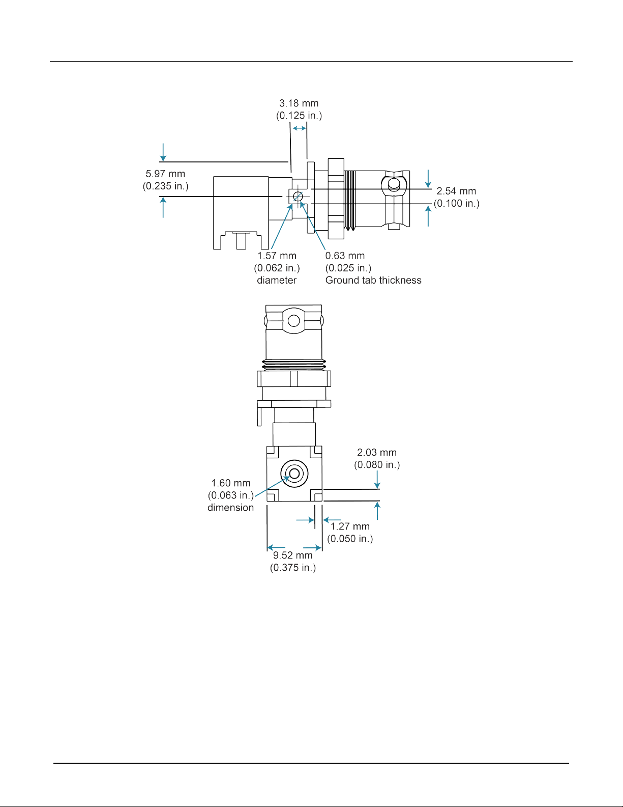
Dimensions
Model TRX-1100V-PCBCONN High-Voltage Female PCB Connector Instructions
Figure 3: TRX-1100V-PCBCONN dimensions - side and front
071368700 / September 2019 3
Page 4
Model TRX-1100V-PCBCONN High-Voltage Female PCB Connector Instructions
4 071368700 / September 2019
Page 5

Model TRX-1100V-PCBCONN High-Voltage Female PCB Connector Instructions
PCB hole pattern
Recommended printed circuit board hole pattern dimensions.
Figure 4: TRX-1100V-PCBCONN PCB hole pattern
071368700 / September 2019 5
Page 6

Model TRX-1100V-PCBCONN High-Voltage Female PCB Connector Instructions
Characteristics
Characteristic impedance:
Nonconstant
nsulation resistance:
I
15
4 x 10
Voltage rating:
Ω minimum
Center contact to intermediate 500 V
RMS
Intermediate contact to outer body 1000 V
ectric withstanding voltage:
Diel
Center contact to intermediate 1500 V
RMS
Intermediate contact to outer body 2500 V
Operat
ing environment: 0 °C to 50 °C up to 70% relative humidity at ≤ 35 °C
RMS
RMS
6 071368700 / September 2019
Page 7

Safety precautions
The following safety precautions should be observed before using this product and any associated instrumentation. Although
some instruments and accessories would normally be used with nonhazardous voltages, there are situat ions where hazardous
conditions may be present.
This product is intended for use by personnel who recognize shock hazards and are familiar with the safet y prec autions required
to avoid possible injury. Read and follow all installation, operation, and maintenance information carefully before using the
product. Refer to the user documentation for complete product specifications.
If the product is used in a manner not specified, the protection provided b y the product warranty may be impaired.
The types of product users are:
Responsible body is the individual or group responsible for the use and maintenance of equipment, for ensuring that the
equipment is operated within its specifications and operating limits, and for ensuring that operators are adequately trained.
Operators use the product for its i ntended function. They must be trained in electrical safety procedures and proper use of the
instrument. They must be protected from electric shock and contact with hazardous live circuits.
Maintenance personnel perform routine procedures on the product to keep it operating properly, for example, s etting the line
voltage or replacing consumable materials. Maintenance procedures are described in the user documentation. The procedures
explicitly state if the operator may perform them. Otherwise, t hey should be performed only by service pe r sonnel.
Service personnel are trained to work on live circuits, perform saf e i ns tallations, and repair products . Only properly trained
service personnel may perform ins tallation and service procedures.
Keithley products are designed f or use with electrical signals that are measurement, control, and data I/O connections, with low
transient overvoltages, and mus t not be directly connected to m ai ns voltage or to voltage sources with high transient
overvoltages. Measurement Cat egory II (as referenced in IEC 60664) connections require protection for high transient
overvoltages often associated with local AC mains connections. Certain Keithley measuring instruments may be connected to
mains. These instruments will be mar k ed as category II or higher.
Unless explicitly allowed in the spec i fications, operating manual, and instrument labels, do not connect any instrument to mains.
Exercise extreme caution when a shock hazar d i s present. Lethal voltage may be pres ent on cable connector jacks or test
fixtures. The American National S tandards Institute (ANSI) states that a shock hazard exists when volta ge l evels greater than
30 V RMS, 42.4 V peak, or 60 VDC are present. A good safety practice is to expect that hazardous voltage is present in any
unknown circuit before measuring.
Operators of this product must be protec ted from electric shock at all tim es. The responsible body must ensure t hat operators
are prevented access and/or insulated from every connection point. In s ome cases, connections must be expose d to potential
human contact. Product operators i n these circumstances must be trained to protect themselves from the risk of el ec tric shock. If
the circuit is capable of operating at or above 1000 V, no conductive part of the circuit may be exposed.
For maximum safety, do not touch the product, test cables, or any other instruments while power is applied to t he c i rcuit under
test. ALWAYS remove power from the entire test system and discharge any capacitors before: connecting or disconnecting
cables or jumpers, installing or rem oving switching cards, or making i nternal changes, such as installing or removing jumpers.
Do not touch any object that could provide a current path to the common side of the circuit under test or power line (earth)
ground. Always make measurements with dry hands while standing on a dry, insulated surface capable of withstanding the
voltage being measured.
For safety, instruments and acc essories must be used in accordance with the operating instructions. If the instruments or
accessories are used in a manner not s pecified in the operating instructions, the protection provided by t he equipment may be
impaired.
Do not exceed the maximum signal levels of the instruments and accessori es . Maximum signal levels are defined in the
specifications and operating inf or mation and shown on the instrument panels, test fixture panels, and switching cards.
Chassis connections must only be us ed as shield connections for measuring circuits, NOT as protective earth (safety ground)
connections.
The WARNING heading in the user documentation explains hazards that might result in personal injury or death. Always read
the associated information ver y car efully before performing the indic ated procedure.
071368700 / September 2019 7
Page 8

The CAUTION heading in the user documentation explains hazards that could damage the ins trument. Such damage may
invalidate the warranty.
The CAUTION heading with the
injury or damage the instrument. Always read the associated information very carefully before performing the indicated
procedure. Damage to the instrument may invalidate the warranty.
Instrumentation and accessories shall not be connected to humans.
Before performing any maintenance, disconnect the line cord and all test cables.
To maintain protection from electric shock and fire, replacement components in mains circuits — inclu ding the power
transformer, test leads, and input j ac ks — must be purchased from Keithley. Standard fuses with applicable national safety
approvals may be used if the rating and type are the same. The detachable mains power cord provided with the instrument may
only be replaced with a similarl y rated power cord. Other components that are not safety-related may be purchased from other
suppliers as long as they are equival ent to the original component (note that selected parts should be purchased only through
Keithley to maintain accuracy and functionality of the product). If you are unsure about the applicability of a replacement
component, call a Keithley office for information.
Unless otherwise noted in product-specific literature, Keithley instruments are designed to operate indoors only, in the following
environment: Altitude at or below 2,000 m (6,562 ft); temperature 0 °C to 50 °C (32 °F to 122 °F); and pollution degree 1 or 2.
To clean an instrument, use a cloth dampened with deionized water or mild, water-based cleaner. Clean the exterior of the
instrument only. Do not apply cleaner directly to the instrument or allow liquids to enter or spill on the instrument. Products that
consist of a circuit board with no case or chassis (e.g., a data acquisition board for installation into a c omputer) should never
require cleaning if handled acc or ding to instructions. If the board becomes contaminated and operation is affected, the board
should be returned to the factor y for proper cleaning/servicing.
Safety precaution revision as of June 2017.
symbol in the user documentation expl ains hazards that could result in m oder ate or minor
8 071368700 / September 2019
 Loading...