

Page 1

Keithley Instruments
Model TRX-1100V-CONN
071368600 / September 2019
1
28775 Aurora Road
Cleveland, Ohio 44139
1-800-935-5595
tek.com/keithley
3-Slot Male HV Triaxial Cable Connector Instructions
Description
The Keithley Instruments TRX-1100V-CONN is a 3-slot male voltage triaxial cable connector rated for 1100 V.
This connector can be used in applications that use the Keithley Instruments Model 2470 High Voltage
SourceMeter
combined with DC measurement capability and broad testing flexibility.
®
Instrument. It can be used for instrument test i ng that requires high voltage and high throughput
Figure 1: TRX-1100V-CONN
This connector is commonly mated to the Keithley Instruments TRX-1100V-PCBCONN High-Voltage Female
PCB Connector. It is intended for use with the Keithley Instruments SC-22 Triaxial Cable, which is an
unterminated cable. Instructions for insta ll i ng the TRX-1100V-CONN onto a SC-22 cable are provided i n this
document. The connector and cable assembly is shown in the following figure.
Figure 2: Fully assembled TRX-1100V-CONN
*P071368600*
Page 2

Model TRX-1100V-CONN 3-Slot Male HV Triaxial Cable Connector Instructions
This triaxial connector is shipped with purple heat-s
installed on the SC-22 cable. The purple marking indicates that t he cable and connector assembly is rated for
up to 1500 V and conforms to IEC 61010-1 and IEC 61010-2-30 safety standards. The purple marking also
indicates that they can be attached to other connectors with purple markings, such as the FORCE and
SENSE connectors on the Model 2470 rear panel, shown in the following figure.
Figure 3: Model 2470 rear-panel purple connections
hrink tubing. As shown in the previous figure, it should be
Do not attach male triaxial connectors without purple markings to female connectors with
purple markings. Triaxial connectors without purple markings are not rated for high voltage.
Mating incompatible connectors can cause damage to the connectors.
Dimensions
Figure 4: TRX-1100V-CONN connector dimensions
2 071368600 / September 2019
Page 3

Model TRX-1100V-CONN 3-Slot Male HV Triaxial Cable Connector Instructions
Triaxial cable connector electrical characteristics
Characteristic impedance:
Nonconstant
Insulation resistance:
4
x 10 Ω
Voltage rating:
15
minimum
Center contact to intermediate 500 V
Intermediate contact to outer body 1000 V
Dielectric withstanding voltage:
Center contact to intermediate 1500 V
Intermediate contact to outer body 2500 V
Operating environment: 0 °C to 50 °C up to 70% relative humidity at ≤ 35 °C
RMS
RMS
RMS
RMS
SC-22 triaxial cable construction
Figure 5: SC-22 triaxial cable dimensions
SC-22 electrical characteristics
Characteristic impedance:
40 Ω nominal center conductor to inner shield
15.3 Ω nominal shield to shield
Center conductor resistance:
< 0.1 Ω per 0.3048 cm (1 foot)
Voltage breakdown:
2655 volt DC minimum between shields
Flexural noise:
Peak-to-peak ≤ 7 mV
Leakage resistance (3.048 m [3 ft] cable length):
Center conductor to inner shield > 1.2 x 10
Inner shield to outer shield > 1.6 x 10
071368600 / September 2019 3
11
Ω at 1200 V
11
Ω at 1600 V
Page 4

Model TRX-1100V-CONN 3-Slot Male HV Triaxial Cable Connector Instructions
TRX-1100V-CONN assembly instructions
The TRX-1100V-CONN needs to be assembled before use. The following figures and instructions guide you
through this process. See the following figure and use it to help guide you step-by-step with the assembly .
Note that you will have to prepare the SC-22 triaxial cable in order to insert it in the TRX-1100V-CONN. The
internal triaxial cable wire must be stripped to the proper dimensions to ensure the correct insertion depth i n the
connector. Excessive exposed conductor length presents electrical shock hazards to equipm ent and personnel.
If the strip length is too short, improper terminat i on will result due to the lack of electrical conductive surfac e
area making contact with the terminal conductor.
Excessive exposed conductor length can result in electrical shock hazards to equipmen t and
personnel. To prevent electrical shock that could cause injury or death, make sure the
stripped wire is the correct length.
Figure 6: TRX-1100V-CONN exploded view
Equipment needed for assembly:
A cable ringing tool or wire stripper
Cleaning solvent for removal of exposed graphite lu bricant
A torque wrench
4 071368600 / September 2019
Page 5

Model TRX-1100V-CONN 3-Slot Male HV Triaxial Cable Connector Instructions
To prepare the SC-22 cable for assembly to the TRX-1100V-CONN:
1. Use the cable ringing tool or wire stripper to strip the cable to the proper dimensions.
Figure 7: Strip SC-22 cable
2. Remove the graphite lubricant applied to the diele ct ric (layer five in the following figure).
Figure 8: Prepare SC-22 cable
071368600 / September 2019 5
Page 6
Model TRX-1100V-CONN 3-Slot Male HV Triaxial Cable Connector Instructions
To assemble the triaxial male HV connector and SC-22 triaxial cable:
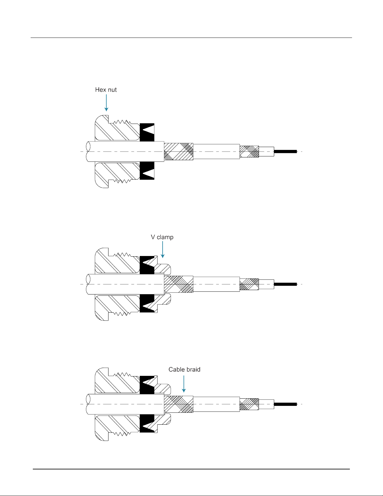
1. Slide the hex nut and V gasket onto the SC-22 triaxial cable as shown in the following figure.
Figure 9: Add hex nut and V gasket to triax cable
2. Install the V clamp as shown in the following figure. Carefully seat the V clamp into the V gasket when
i
nserting. The sharp edge of the V clamp must split t he gasket to seal properly.
Figure 10: Add V clamp
3. Flare the exposed outer shield cable braid back over the V clamp, as shown in the following figure. Make
s
ure you trim the excess braid so it does not protrude from the connector.
Figure 11: Flare braid over V clamp
6 071368600 / September 2019
Page 7
Model TRX-1100V-CONN 3-Slot Male HV Triaxial Cable Connector Instructions
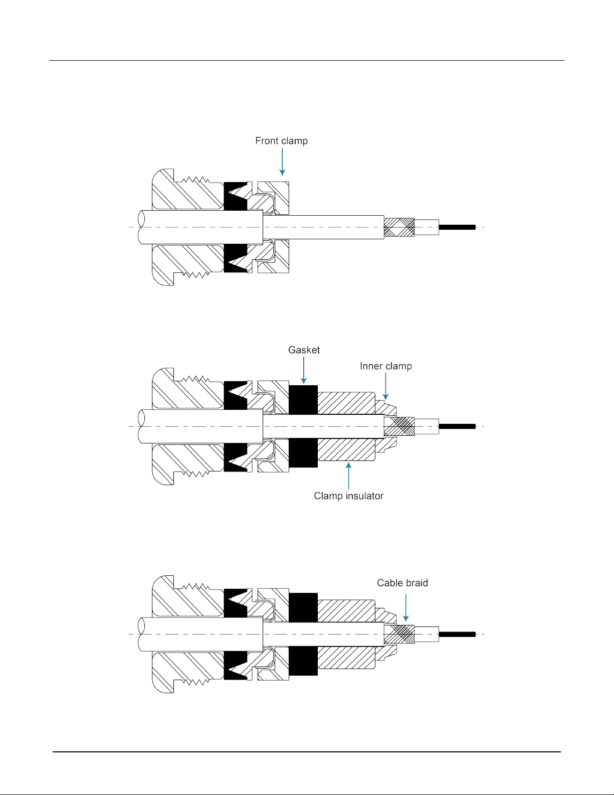
4. Slide the front clamp against the braid as shown in the following figure. Make sure to fully seat the front
clamp onto the V clamp.
Figure 12: Add front clamp
5. Install the gasket, clamp insulator, and inner clamp, as shown in the following figure.
Figure 13: Add gasket, clamp insulator, and inner clamp
6. Flare the exposed inner shield cable braid back over the inner clamp as shown in the following figure. Make
s
ure you trim the excess braid so it does not prot rude from the connector.
Figure 14: Flare braid over slotted clamp
071368600 / September 2019 7
Page 8

Model TRX-1100V-CONN 3-Slot Male HV Triaxial Cable Connector Instructions
7. Install the slotted clamp, support insulator, and c enter contact. Crimp the center contact to the center
conductor cable as shown in the following figure.
Figure 15: Add slotted clamp, support insulator, and center contact
8. Slide the outer contact over the center contact and support insulator as shown in the following figure. Make
s
ure to seat the outer contact fully onto the slott ed clamp.
Figure 16: Add contact assembly
8 071368600 / September 2019
Page 9

Model TRX-1100V-CONN 3-Slot Male HV Triaxial Cable Connector Instructions
9. Insert the terminated cable assembly into the rear of the connector body as shown in the following
figure.
10. Tighten the cable nut with a wrench to 3.39 Newton meters (30 inch-pounds).
F
igure 17: Add connector body to terminated cable assembly
071368600 / September 2019 9
Page 10

Safety precautions
The following safety precautions should be observed before using this product and any associated instrumentation. Although
some instruments and accessories would normally be used with nonhaz ardous voltages, there are situations where hazardous
conditions may be present.
This product is intended for use by personnel who recognize shock hazards and are familiar with the safet y prec autions required
to avoid possible injury. Read and follow all installation, operation, and maintenance information carefully before using the
product. Refer to the user documentation for complete product specifications.
If the product is used in a manner not specified, the protection provided by the product warranty may be impaired.
The types of product users are:
Responsible body is the individual or group responsible for the use and maintenance of equipment, for ensuring that the
equipment is operated within its specifications and operating limits, and for ensuring that oper ators are adequately trained.
Operators use the product for its i ntended function. They must be trained in electrical safety procedures and proper use of the
instrument. They must be protected from electric shock and contact with hazardous live circuits.
Maintenance personnel perform routine procedures on the product to keep it operating properly, for example, s etting the line
voltage or replacing consumable materials. Maintenance procedures are described in the user documentation. The procedures
explicitly state if the operator may perform them. Otherwise, t hey should be performed only by service pe r sonnel.
Service personnel are trained to work on live circuits, perform saf e i ns tallations, and repair products . Only properly trained
service personnel may perform ins tallation and service procedures.
Keithley products are designed f or use with electrical signals that are measurement, control, and data I /O connections, with low
transient overvoltages, and mus t not be directly connected to mains voltage or to voltage sources with high transient
overvoltages. Measurement Cat egory II (as referenced in IEC 60664) connections require protection for high transient
overvoltages often associated with local AC mains connections. Certain Keithley measuring instrument s may be connected to
mains. These instruments will be mar k ed as category II or higher.
Unless explicitly allowed in the spec i fications, operating manual, and instrument labels, do not connect any instrument to mains.
Exercise extreme caution when a shock hazard is present. Lethal voltage may be present on cable connector jacks or test
fixtures. The American National S tandards Institute (ANSI) states that a shock hazard exists when voltage levels greater than
30 V RMS, 42.4 V peak, or 60 VDC are present. A good safety practice is to expect that hazardous voltage is present in any
unknown circuit before measuring.
Operators of this product must be prot ected from electric shock at all t imes. The responsible body must ensure that operators
are prevented access and/or insulated from every connection point. In s ome cases, connections must be expose d to potential
human contact. Product operators i n these circumstances must be trained to protect themselves from the risk of el ec tric shock. If
the circuit is capable of operating at or above 1000 V, no conductive part of the circuit may be exposed.
For maximum safety, do not touch the product, test cables, or any other in struments while power is applied to the circuit under
test. ALWAYS remove power from the entire test system and discharge any capacitors before: connecting or di s connecting
cables or jumpers, installing or rem oving switching cards, or making i nternal changes, such as installing or removing jumpers.
Do not touch any object that could provide a current path to the common side of the circuit under test or power line (e arth)
ground. Always make measurements with dry hands while standing on a dry, ins ulated surface capable of withsta nding the
voltage being measured.
For safety, instruments and accessories must be used in accordance with the operating instructions. If the instruments or
accessories are used in a manner not s pecified in the operating instruct ions, the protection provided by the equipment may be
impaired.
Do not exceed the maximum signal lev els of the instruments and accessories. Maximum signal levels are defined in the
specifications and operating inf or mation and shown on the instrument panels, test fixture panels, and switching cards.
Chassis connections must only be used as shield connections for measuring circuits, NOT as protective earth (safety ground)
connections.
The WARNING heading in the user documentation explains hazards that might result in personal i njury or death. Always read
the associated information very car efully before performing the indic ated procedure.
10 071368600 / September 2019
Page 11

The CAUTION heading in the user documentation explains hazards that could damage the ins trument. Such damage may
invalidate the warranty.
The CAUTION heading with the
injury or damage the instrument. Always read the associated information very carefully before performing the indicated
procedure. Damage to the instrument may invalidate the warranty.
Instrumentation and accessories shall not be connected to humans.
Before performing any maintenance, disconnect the line cord and all test cables.
To maintain protection from electric shock and fire, replacement components in mains circuits — inclu ding the power
transformer, test leads, and input j ac ks — must be purchased from Keithley. Standard fuses with applicable national safety
approvals may be used if the rating and type are the same. The detachable m ains power cord provided with the instrument may
only be replaced with a similarly rated power cord. Other components that are not safety-related may be purchased from other
suppliers as long as they are equival ent to the original component (note that selected parts should be purc hased only through
Keithley to maintain accuracy and f unctionality of the product). If you are unsure about the applicability of a replacement
component, call a Keithley office for information.
Unless otherwise noted in product-specific literature, Keithley instruments are designed to operat e i ndoors only, in the following
environment: Altitude at or below 2,000 m (6,562 ft); temperature 0 °C to 50 °C (32 °F to 122 °F); and pollution degree 1 or 2.
To clean an instrument, use a cloth dampened with deionized water or mild, water-based cleaner. Clean the exterior of the
instrument only. Do not apply cleaner directly to the instrument or allow liquids to enter or spill on the instrument. Products that
consist of a circuit board with no case or chassis (e.g., a data acquisition board for installation into a computer) should never
require cleaning if handled acc or ding to instructions. If the board becomes contaminated and operation is affected, the board
should be returned to the factor y for proper cleaning/servicing.
Safety precaution revision as of J une 2017.
symbol in the user documentation explains hazards that could result in moderate or minor
071368600 / September 2019 11
 Loading...