

Page 1

TDP7700 Series
TriMode™ Probes
User Manual
*P071355900*
071-3559-00
Page 2

Page 3

TDP7700 Series
TriMode™ Probes
User Manual
www.tek.com
071-3559-00
Page 4

Copyright © Tektronix. All rights reserved. Licensed software products are owned by Tektronix or its subsidiaries or suppliers, and are
protected by national copyright laws and international treaty provisions. Tektronix products are covered by U.S. and foreign patents, issued
and pending. Information in this publication supersedes that in all previously published material. Specifications and price change privileges
reserved.
TEKTRONIX and TEK are registered trademarks of Tektronix, Inc.
Contacting Tektronix
Tektronix, Inc.
14150 SW Karl Braun Drive
P.O. Box 500
Beaverton, OR 97077
USA
For product information, sales, service, and technical support:
■
In North America, call 1-800-833-9200.
■
Worldwide, visit www.tek.com to find contacts in your area.
Page 5

Warranty
Tektronix warrants that this product will be free from defects in materials and workmanship for a period of one (1) year from the date of
shipment. If any such product proves defective during this warranty period, Tektronix, at its option, either will repair the defective product
without charge for parts and labor, or will provide a replacement in exchange for the defective product. Parts, modules and replacement
products used by Tektronix for warranty work may be new or reconditioned to like new performance. All replaced parts, modules and
products become the property of Tektronix.
In order to obtain service under this warranty, Customer must notify Tektronix of the defect before the expiration of the warranty period and
make suitable arrangements for the performance of service. Customer shall be responsible for packaging and shipping the defective
product to the service center designated by Tektronix, with shipping charges prepaid. Tektronix shall pay for the return of the product to
Customer if the shipment is to a location within the country in which the Tektronix service center is located. Customer shall be responsible
for paying all shipping charges, duties, taxes, and any other charges for products returned to any other locations.
This warranty shall not apply to any defect, failure or damage caused by improper use or improper or inadequate maintenance and care.
Tektronix shall not be obligated to furnish service under this warranty a) to repair damage resulting from attempts by personnel other than
Tektronix representatives to install, repair or service the product; b) to repair damage resulting from improper use or connection to
incompatible equipment; c) to repair any damage or malfunction caused by the use of non-Tektronix supplies; or d) to service a product
that has been modified or integrated with other products when the effect of such modification or integration increases the time or difficulty
of servicing the product.
Page 6

THIS WARRANTY IS GIVEN BY TEKTRONIX WITH RESPECT TO THE PRODUCT IN LIEU OF ANY OTHER WARRANTIES, EXPRESS
OR IMPLIED. TEKTRONIX AND ITS VENDORS DISCLAIM ANY IMPLIED WARRANTIES OF MERCHANTABILITY OR FITNESS FOR A
PARTICULAR PURPOSE. TEKTRONIX' RESPONSIBILITY TO REPAIR OR REPLACE DEFECTIVE PRODUCTS IS THE SOLE AND
EXCLUSIVE REMEDY PROVIDED TO THE CUSTOMER FOR BREACH OF THIS WARRANTY. TEKTRONIX AND ITS VENDORS WILL
NOT BE LIABLE FOR ANY INDIRECT, SPECIAL, INCIDENTAL, OR CONSEQUENTIAL DAMAGES IRRESPECTIVE OF WHETHER
TEKTRONIX OR THE VENDOR HAS ADVANCE NOTICE OF THE POSSIBILITY OF SUCH DAMAGES.
[W2 – 15AUG04]
Page 7

Table of Contents
Important safety information ............................................................................................................................... vii
General safety summary ............................................................................................................................... vii
Terms in the manual ...................................................................................................................................... ix
Terms on the product ..................................................................................................................................... x
Symbols on the product .................................................................................................................................. x
Compliance Information ...................................................................................................................................... xi
Environmental compliance ............................................................................................................................ xi
Key features
Operating considerations
TDP7700 Series TriMode Probes User Manual i
Page 8

Table of Contents
Installation
Installation overview ....................................................................................................................................... 5
Connect to the host instrument ...................................................................................................................... 7
Connect accessories to the TekFlex connector ........................................................................................... 11
TriMode probing ........................................................................................................................................... 13
Probe comp box controls and indicators ...................................................................................................... 15
Status LED ............................................................................................................................................. 15
Input mode buttons and LEDs ................................................................................................................ 16
Functional check
Functional check .......................................................................................................................................... 19
Basic operation
Offset voltage ............................................................................................................................................... 30
ii TDP7700 Series TriMode Probes User Manual
Page 9

Table of Contents
Using the offset voltages .............................................................................................................................. 30
Probe setup panel ........................................................................................................................................ 31
Selecting the offset voltage .................................................................................................................... 33
Offset tracking set up ............................................................................................................................. 34
Termination voltage ................................................................................................................................ 36
Probe tip information .............................................................................................................................. 38
Improving measurement accuracy ............................................................................................................... 38
Probe architecture .................................................................................................................................. 38
Solder-in tip connection wire length ....................................................................................................... 40
Using offset voltage to extend TDP7700 series solder-in tip input voltage range .................................. 41
Making single ended measurements using the P77BRWSR differential probe tip ................................. 41
Temperature compensation ................................................................................................................... 42
DSP correction ....................................................................................................................................... 42
Solder tip measurement configuration .................................................................................................... 43
Connecting to a circuit board ....................................................................................................................... 44
Tip soldering ........................................................................................................................................... 50
TDP7700 Series TriMode Probes User Manual iii
Page 10

Table of Contents
Recommended equipment ..................................................................................................................... 50
Precautions when connecting to the circuit ............................................................................................ 60
Care of TekFlex solder-in tips ................................................................................................................ 61
Probe handling best practices
Best practices ............................................................................................................................................... 63
Accessories and options
Standard accessories ................................................................................................................................... 67
Optional accessories .................................................................................................................................... 69
Maintenance
Browser tip replacement .............................................................................................................................. 75
Error conditions ............................................................................................................................................ 77
LED indicators ........................................................................................................................................ 77
iv TDP7700 Series TriMode Probes User Manual
Page 11

Table of Contents
Signal display ......................................................................................................................................... 78
Measurement errors ............................................................................................................................... 78
Handling the probe ....................................................................................................................................... 79
Cleaning the probe ....................................................................................................................................... 80
Returning the probe for servicing ................................................................................................................. 81
TDP7700 Series TriMode Probes User Manual v
Page 12

Table of Contents
vi TDP7700 Series TriMode Probes User Manual
Page 13

Important safety information
This manual contains information and warnings that must be followed by the user for safe operation and to keep the product in a
safe condition.
General safety summary
Use the product only as specified. Review the following safety precautions to avoid injury and prevent damage to this product or
any products connected to it. Carefully read all instructions. Retain these instructions for future reference.
This product is not intended for detection of hazardous voltages.
Observe all terminal ratings. To avoid fire or shock hazard, observe all rating and markings on the product. Consult the product
manual for further ratings information before making connections to the product.
Do not apply a potential to any terminal, including the common terminal, that exceeds the maximum rating of that terminal.
Do not operate without covers. Do not operate this product with covers or panels removed, or with the case open. Hazardous
voltage exposure is possible.
Avoid exposed circuitry. Do not touch exposed connections and components when power is present.
TDP7700 Series TriMode Probes User Manual vii
Page 14

Important safety information
Do not operate in wet/damp conditions. Be aware that condensation may occur if a unit is moved from a cold to a warm
environment.
Do not operate in an explosive atmosphere.
Keep product surfaces clean and dry. Remove the input signals before you clean the product.
Probes and test leads
Remove all probes, test leads and accessories that are not in use.
Inspect the probe and accessories. Before each use, inspect probe and accessories for damage (cuts, tears, or defects in the
probe body, accessories, or cable jacket). Do not use if damaged.
viii TDP7700 Series TriMode Probes User Manual
Page 15
Important safety information
Terms in the manual
These terms may appear in this manual:
WARNING. Warning statements identify conditions or practices that could result in injury or loss of life.
CAUTION. Caution statements identify conditions or practices that could result in damage to this product or other property.
TDP7700 Series TriMode Probes User Manual ix
Page 16
Important safety information
Terms on the product
These terms may appear on the product:
■
DANGER indicates an injury hazard immediately accessible as you read the marking.
■
WARNING indicates an injury hazard not immediately accessible as you read the marking.
■
CAUTION indicates a hazard to property including the product.
Symbols on the product
When this symbol is marked on the product, be sure to consult the manual to find out the nature of the potential
hazards and any actions which have to be taken to avoid them. (This symbol may also be used to refer the user to
ratings in the manual.)
The following symbols may appear on the product:
x TDP7700 Series TriMode Probes User Manual
Page 17

Compliance Information
This section lists the EMC (electromagnetic compliance), safety, and environmental standards with which the instrument
complies. This product is intended for use by professionals and trained personnel only; it is not designed for use in households or
by children.
Environmental compliance
This section provides information about the environmental impact of the product.
Restriction of hazardous substances
Complies with RoHS2 Directive 2011/65/EU.
Product end-of-life handling
Observe the following guidelines when recycling an instrument or component:
Equipment recycling. Production of this equipment required the extraction and use of natural resources. The equipment may
contain substances that could be harmful to the environment or human health if improperly handled at the product’s end of life.
To avoid release of such substances into the environment and to reduce the use of natural resources, we encourage you to
recycle this product in an appropriate system that will ensure that most of the materials are reused or recycled appropriately.
TDP7700 Series TriMode Probes User Manual xi
Page 18
Compliance Information
This symbol indicates that this product complies with the applicable European Union requirements according to
Directives 2012/19/EU and 2006/66/EC on waste electrical and electronic equipment (WEEE) and batteries. For
information about recycling options, check the Tektronix Web site (www.tek.com/productrecycling).
xii TDP7700 Series TriMode Probes User Manual
Page 19

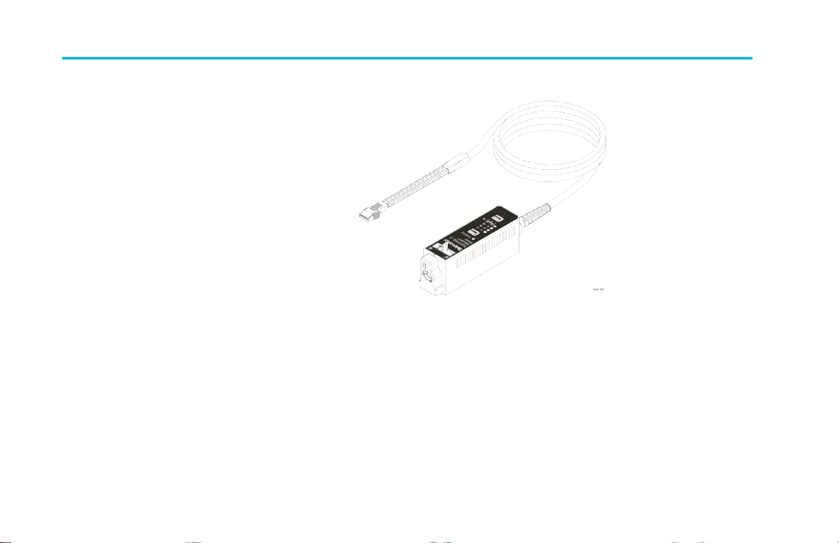
Key features
The TDP7700 Series TriMode Probes allow you to take differential, single-ended, and common mode measurements with one
probe connection. Key features include:
TDP7700 Series TriMode Probes User Manual 1
Page 20
Key features
■
Low loading for low power standards like
MIPI D-PHY
■
Thin flexible solder-in tips that can fit into
tight spaces on a device under test
■
Lightweight and Flexible probe cable and
head
■
TekFlex™ connector technology that
makes the probe easy to connect to
accessories
■
Optional 2.92 mm adapter for connecting
to 50 Ω RF test points
■
Browser accessory with adjustable tip and auto corrected response to pin spacing
■
Full AC calibration of the probe and accessory tips with unique S-parameters automatically downloaded to the scope at
plug-in.
■
Flexible solder-in tips and main probe cable
■
Solder-in tips operate at extended temperature range
2 TDP7700 Series TriMode Probes User Manual
Page 21
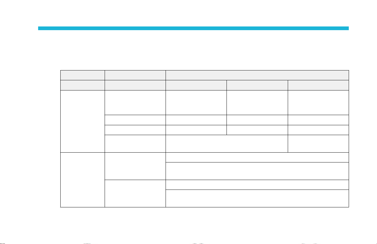
Operating considerations
Table 1: TDP7700 Series TriMode probes
Characteristic Description Specification
Input Voltage Dynamic range 2.5 Vpp (single-ended)
Operating voltage window ±5.25 V ±10.0 V ±4.0 V
Offset voltage range -4 V to +4 V -10 V to +10 V -4 V to +4 V
Maximum non-destructive
input voltage
Temperature Operating Probe compensation box: 0 °C to 50 °C (32 °F to 122 °F)
Non-operating Probe compensation box: -20 °C to 60 °Cg (-4 °F to 140 °F)
TekFlex solder-in tips P77BRWSR P77C292MM adapter
6.0 Vpp (single-ended)
5.0 Vpp (differential input)
-15 V to +15 V (tip attached or detached) -5 V to +5 V
Probe cable, solder tips, and P77C292MM adapter: -35 °C to 85 °C (-31 °F to
185 °F); Minimum Airflow required 46°C to 85°C (114.8 °F to 185 °F)
Probe cable, solder tips, and P77C292MM adapter: -35 °C to 85 °C (-31 °F to
185 °F)
12.0 Vpp (differential
input)
1.2 Vpp (single-ended)
2.0 Vpp (differential input)
TDP7700 Series TriMode Probes User Manual 3
Page 22
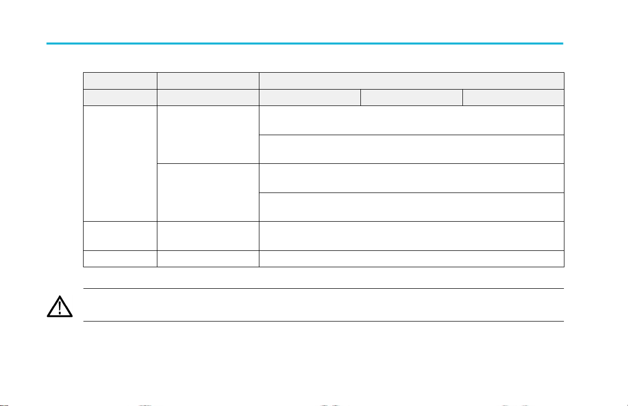
Operating considerations
Characteristic Description Specification
TekFlex solder-in tips P77BRWSR P77C292MM adapter
Humidity Operating Probe compensation box: 5% to 90% Relative Humidity (%RH) at up to 40 °C
non-condensing, 5% to 55% RH above 40°C up to 50°C non-condensing
Probe cable, solder tips, and P77C292MM adapter: 20% to 80% Relative
Humidity (%RH) at up to 50 °C non-condensing
Non-operating Probe compensation box: 5% to 90% Relative Humidity (%RH), at up to 40 °C
non-condensing, 5% to 55% RH above 40 °C up to 60 °C non-condensing
Probe cable, solder tips, and P77C292MM adapter: 10% to 85% Relative
Humidity (%RH), at up to 85 °C non-condensing
Altitude Non-operating Probe Compensation Box, Cable, Tips, and SMA adapter: 12,000 meters
(39,370 feet)
Pollution Degree 2, Indoor use only
CAUTION. To avoid ESD damage to the probe, always use an antistatic wrist strap (provided with your probe), and work at a
static-approved workstation when you handle the probe.
4 TDP7700 Series TriMode Probes User Manual
Page 23
Installation
Installation overview
CAUTION. To avoid ESD damage to the probe, always use an antistatic wrist strap (provided with your probe), and work at a
static-approved workstation when you handle the probe.
1. Connect the probe to the host instrument.
If it is the first time the probe has been connected to the oscilloscope, the oscilloscope will download the S-parameters
stored in the probe and cycle through the LEDs. Once the oscilloscope has stored the S-parameters for the probe, it doesn’t
matter which channel the probe is plugged into. The stored S-parameters will be available for any channel the probe is
moved to.
2. Connect the probe tip to the TekFlex connector on the probe.
When a tip is inserted into the probe for the first time, the oscilloscope will download the S-parameter data stored in the tip.
3. The probe performs a self test, and then one Input Mode LED remains on. The Status LED is also lit green.
4. Double-tap the channel badge to open the configuration menu.
TDP7700 Series TriMode Probes User Manual 5
Page 24

Installation
5. Tap the Probe Setup panel to open the Probe Setup panel to confirm probe settings.
6. Use the Probe Setup panel to set the probe parameters as described in the Basic operation section.
6 TDP7700 Series TriMode Probes User Manual
Page 25
Installation
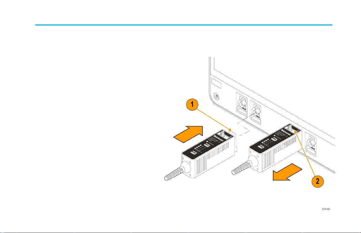
Connect to the host instrument
1. Slide the probe into the FlexChannel
receptacle. The probe clicks into place
when fully engaged.
2. Move the locking lever to the locked
position.
TDP7700 Series TriMode Probes User Manual 7
Page 26

Installation
Disconnect
3. To disconnect the probe, move and hold the locking lever at the unlocked position and pull out the probe.
8 TDP7700 Series TriMode Probes User Manual
Page 27
Installation
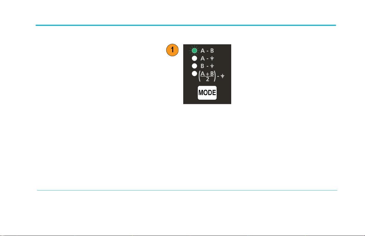
Probe and probe tip power-on
After the connection to the oscilloscope is
made:
1. The probe cycles through all mode LEDs
during a self-test and while S-Parameters
are transferred to the instrument, and
then the A – B Input Mode LED remains
on. If a probe tip is attached, an LED on
the tip also turns on when properly
attached to the probe
1
.
2. The probe transfers data from the probe
and tip to the host instrument.
The data transfer takes a few minutes, and is only done when the host instrument discovers a new probe or new probe tip.
The data transfer only occurs on instruments that are fully compatible with the probe.
1
The P77C292MM does not contain an LED.
TDP7700 Series TriMode Probes User Manual 9
Page 28

Installation
3. After the data transfer is done, the probe is ready for a functional check. See Functional check on page 19.
If the probe’s status LED is red, the power-on self-test likely failed. See Error conditions on page 77.
10 TDP7700 Series TriMode Probes User Manual
Page 29

Installation
Connect accessories to the TekFlex connector
All of the TDP7700 accessories mate with the new TekFlex (zero insertion force) connector. This connector provides an easy
connection for attaching to the TDP7700 series accessories. The following procedures show the steps for connecting probe tips
to the TekFlex connector; the procedures for connecting to other accessories are similar.
TDP7700 Series TriMode Probes User Manual 11
Page 30
Installation
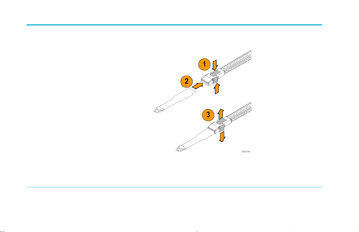
Connect the tip to the probe TekFlex connector as follows:
1. Pinch the TekFlex connector to open the
jaws.
2. Orient the tip with the probe head (notch
to the left) and slide the tip connector into
the TekFlex connector.
A green LED will light up when the tip is
inserted
1
. The LED is the first indication
that the tip is powered and is inserted.
You also need to confirm that the
connector pins on the TekFlex connector
fit through the alignment holes on the tip.
3. Once the tip is fully inserted, release the pinch and the TekFlex connector closes. When closed and properly seated, the
top of connector will be flush with the probe tip housing.
1
The P77C292MM does not contain an LED.
12 TDP7700 Series TriMode Probes User Manual
Page 31

Installation
TriMode probing
TriMode probing
The TriMode feature allows you to view two
single-ended signals and the resultant
differential waveform and common-mode
voltage without moving the probe connection.
Press the Input Mode button to cycle through
the waveform views.
This example shows a typical signal on the A
and B inputs. The resultant differential
waveform and common-mode voltage are
shown.
TDP7700 Series TriMode Probes User Manual 13
Page 32

Installation
14 TDP7700 Series TriMode Probes User Manual
Page 33

Installation
Probe comp box controls and indicators
Status LED
The Status LED glows red under the following
conditions:
■
Probe power-on self test failure
■
Probe over-temperature detected
■
The input voltage on either the A or B
input exceeds the allowable limit or more
than 50 mA is drawn by the inputs on the
P77C292MM
The Status LED is green when the condition
causing the warning is removed and under
normal operation. A notifier message of a
probe status condition can also be seen on the
oscilloscope.
TDP7700 Series TriMode Probes User Manual 15
Page 34

Installation
CAUTION. Do not exceed the input voltage limits of the probe and probe tips. The probe or oscilloscope circuits may be
damaged if the limits are exceeded. Make sure that you understand and work within the limits of the probe and probe tips.
Input mode buttons and LEDs
The TDP7700 Series solder-in tips support TriMode operation. TriMode enables you to switch the probe between four different
measurement types without changing the probe’s connection:
16 TDP7700 Series TriMode Probes User Manual
Page 35

Installation
Press the Input Mode button to select one of
the four TriMode measurements. The modes
cycle in the following sequence:
■
A – B (for differential signal
measurement)
■
A – GND (for A input single-ended
measurement)
■
B – GND (for B input single-ended
measurement)
■
(A + B)/2 – GND (for common mode
measurement)
TDP7700 Series TriMode Probes User Manual 17
Page 36

Installation
18 TDP7700 Series TriMode Probes User Manual
Page 37

Functional check
After you connect the probe to the oscilloscope, you can perform a functional check using either the optional P77DESKEW
deskew fixture designed for the probe or the optional P77C292MM Adapter.
CAUTION. To avoid ESD damage to the probe, always use an antistatic wrist strap (provided with your probe), and work at a
static-approved workstation when you handle the probe.
Functional check
This procedure checks the four TriMode settings on the probe.
It verifies the signal path of both the probe A and B input signals and their combination in the four TriMode settings.
TDP7700 Series TriMode Probes User Manual 19
Page 38

Functional check
Table 2: Required equipment, functional check with probe tip
Item Description Performance Requirement Recommended Example
Oscilloscope FlexChannel Interface Tektronix MSO6 Series
Probe tip Solder tip or Browser tip P77STFLXA
Test board Probe deskew fixture P77DESKEW
Signal generator 100 kHz square wave, 1 V
into 50 Ω 6 Series MSO AFG output
pk-pk
1
1
1
Optional accessory
20 TDP7700 Series TriMode Probes User Manual
Page 39

Functional check
Test setup with the P77DESKEW deskew
fixture
TDP7700 Series TriMode Probes User Manual 21
Page 40

Functional check
1. Connect an SMA cable from a signal source, such as the AFG output connector on the oscilloscope to the A input of the
fixture.
2. Connect the probe to the desired channel of the oscilloscope.
3. Set the oscilloscope to display the connected channel.
4. Connect the included P77STFLXA TekFlex solder in tip to the TDP7700 probe using the pinch to open TekFlex
connector at the end of the main cable. Insert the P77STFLXA in to the plastic clamp on port 1 or 2 of the deskew fixture.
This is done by compressing the spring-loaded clamp, inserting the probe tip input into the clamp, and then releasing the
clamp so that it locks the connection.
5. Connect the deskew fixture to a USB power source, such as the front panel USB connector on the oscilloscope. The
LEDs on the fixture will turn on.
6. If a P77BRWSR tip is used instead of a solder-down tip to make connection to the Deskew Fixture, the TekFlex
connector of the probe should first be connected to the P77BRWSR tip. The P77BRWSR tip inputs must then be pressed
into place against the A and B signal trace on the deskew fixture. Either of two sets of A and B signal trace connection
points may be used
22 TDP7700 Series TriMode Probes User Manual
Page 41

Functional check
Test setup with the P77C292MM adapter
1. Connect the probe to the desired channel
of the oscilloscope. Connect the probe to
the P77C292MM adapter. Set the
oscilloscope to display the connected
channel.
2. Connect the A cable from the
P77C292MM adapter to the AFG Out
connector.
Test procedure
1. Set the signal generator so that it produces a 1 V
100 kHz square wave.
pk-pk
TDP7700 Series TriMode Probes User Manual 23
Page 42

Functional check
2. Set the probe Input Mode to A-B.
3. Adjust the oscilloscope to display a stable waveform (or press the Autoset button). The test signal is a 100 KHz square
wave. The amplitude of the signal is attenuated by 4X, compared to a single path termination, due to the power splitter
built into the deskew fixture.
4. When you see a stable square waveform, check the amplitude. The attenuated amplitude displayed for the test signal
should be about 250 mVpp.
24 TDP7700 Series TriMode Probes User Manual
Page 43

Functional check
5. Cycle the Input Mode button through the
remaining selections and compare the
displayed waveforms to the waveform
measured in the setup steps.
■
A-B
■
A-GND (same amplitude and polarity
as previously measured)
■
B-GND (the B input is grounded; no
signal is measured)
■
(A+B)/2- GND (half-amplitude, but
the same polarity as previously
measured)
TDP7700 Series TriMode Probes User Manual 25
Page 44

Functional check
6. Change the SMA cable connection from
the Deskew Fixture A input to the B input.
Repeat the displayed waveform checks.
The measurements should be different
as follows:
■
A-B (the polarity of the signal will be inverted due to the B signal inversion, although the p-p amplitude should be the
same)
■
A-GND (the A input is grounded; no signal is measured)
26 TDP7700 Series TriMode Probes User Manual
Page 45

Functional check
■
B-GND (same amplitude but non-inverted polarity compared to the A-B mode)
■
(A+B)/2- GND (half-amplitude, but the same polarity as measured in the B-GND mode)
TDP7700 Series TriMode Probes User Manual 27
Page 46

Functional check
28 TDP7700 Series TriMode Probes User Manual
Page 47

Basic operation
This section includes information about the probe input limits, using the probe controls, and procedures for connecting the probe
to your circuit.
A simplified input model of the probe is shown below to illustrate the probe offset voltage controls. The probe has two
symmetrical signal inputs, the A input and the B input, which you can display independently or in combination by selecting the
appropriate probe input mode. The probe also has independent offset voltage controls for the probe A and B input signals.
Figure 1: Simplified probe input model
TDP7700 Series TriMode Probes User Manual 29
Page 48

Basic operation
Offset voltage
The offset voltage adjusts the probe input dynamic range within the larger probe input operating range. The probe input dynamic
range is the region where an input signal is within the linear operating region of the probe. The probe A and B offset voltages are
set and stored as common settings for all four input modes.
Using the offset voltages
The offset voltage shifts the center of the dynamic range, allowing more resolution for inputs not around ground. The size of the
probe input dynamic range depends on the probe tip that you are using and can also depend on the input mode selected.
To set the offset voltages on the probe, you can use the controls in the Probe Setup panel. See Probe setup panel on page 31.
To display the Probe Setup panel, double tap the channel badge to open the configuration menu. Tap Probe Setup to open the
Probe Setup panel. Make changes to the offset.
30 TDP7700 Series TriMode Probes User Manual
Page 49

Basic operation
Probe setup panel
Use the Probe Setup panel to adjust the probe input settings for the measurement you are taking. To display the Probe Setup
panel, double-tap the channel badge and then tap Probe Setup. The Probe Setup panel can be used to select the TriMode Input
Mode setting and is also used to adjust the offset voltage controls for the probe tip A and B inputs.
The following pages describe the controls and status fields in the Probe Setup panel.
Figure 2: Probe setup panel
TDP7700 Series TriMode Probes User Manual 31
Page 50

Basic operation
Selecting the TriMode input mode
The input Mode button on the probe toggles the internal probe input selector switches among the four input mode selections.
The mode can also be selected from the Mode list in the Probe Setup panel. This TriMode feature allows full characterization
of a differential signal from a single connection.
32 TDP7700 Series TriMode Probes User Manual
Page 51

Basic operation
A-GND mode The A-GND mode is used for making single-ended measurements with the probe A input. The probe ground
input connects the probe tip and main cable shield. The A-GND Mode is designed for minimal coupling from any signal
present on the B input within the A input isolation performance of the probe.
B-GND mode. The B-GND mode is used for making single-ended measurements with the probe B input. The probe ground
input connects the probe tip and main cable shield. The B-GND Mode is designed for minimal coupling from any signal
present on the A input within the B input isolation performance of the probe.
(A+B)/2 mode. The (A+B)/2 Mode is used for making common mode measurements on a differential signal and represents a
capability that previously could only be made using oscilloscope math on multiple channels. For a differential signal, the
common mode measurement indicates the DC bias level and also shows the degree of asymmetry between the A and B
inputs. Since the (A+B)/2 Mode measures the average between the A and B input signals, it eliminates any complementary
differential signal voltage, within the DMRR performance capability of the probe. This measurement also requires a ground
connection to the probe.
Selecting the offset voltage
You can set both the A and B offset voltages to levels that are common for all input modes.
You can enter specific offset values directly in the Offset fields.
TDP7700 Series TriMode Probes User Manual 33
Page 52

Basic operation
There are manual offset voltage value entry fields which also display the current offset voltage settings. An offset voltage entry
field is activated for adjustment by taping the setting window. A single tap activates both the setting window and the general
purpose knobs on the oscilloscope front panel. A second tap in the setting window when activated also brings up a keypad entry
window.
The oscilloscope vertical channel offset control also adjusts the selected Input mode offset voltage field.
Offset tracking set up
The probe A and B signal inputs are sensed, monitored, and averaged by probe internal circuitry and the sensed values are used
by the offset tracking control buttons.
34 TDP7700 Series TriMode Probes User Manual
Page 53

Basic operation
Common Mode Offset Tracking. When this
mode is selected Common Mode Offset is set
to tracking.
Common Mode Tracking automatically sets
the common mode offset to the average of the
inputs (A+B)/2.
Differential Mode Offset Tracking. When this
mode is selected Differential Mode Offset is
set to tracking.
Differential Mode Tracking automatically sets
the differential mode offset to the difference of
the inputs (A-B).
TDP7700 Series TriMode Probes User Manual 35
Page 54

Basic operation
Termination voltage
For the P77C292MM adapter, the termination voltage adjusts the effective probe DC loading of the 50 Ω input termination. Use
the voltage to minimize the DC loading of the probe input signals. By setting the voltage equal to the DC bias voltage of the input
signal, the probe DC loading is nulled out, as if a DC block was inserted. However, unlike a DC block, the signal DC voltage is
still present at the probe input and might require you to adjust the Offset voltage to move the signal into the probe input dynamic
range. There are some signal measurement applications that benefit from the availability of an adjustable termination voltage and
avoid the need for a pair of bias tees.
36 TDP7700 Series TriMode Probes User Manual
Page 55

Basic operation
The probe A and B termination voltages are
common for each of the four input modes.
When using the P77C292MM adapter, the
voltage can be adjusted over a limited
operating range before reaching an overload
condition.If VTerm Tracking is checked, the
termination voltages are set automatically.
TDP7700 Series TriMode Probes User Manual 37
Page 56

Basic operation
Probe tip information
NOTE. Probe tip ID is fully automatic. Manual selection is not required.
When the probe is first connected to the oscilloscope channel, the oscilloscope queries the probe for status information, including
the probe type, serial number, and the model number of the tip that is connected to the probe. The first time a probe or probe tip
is connected to a host oscilloscope, the probe and probe tip serial numbers are logged and the stored S-parameters are
downloaded. If the probe or probe tip are moved to another channel on the same oscilloscope, the logged information is
automatically processed without repeating the download process.
Improving measurement accuracy
This section covers some of the features and characteristics of the probe that can affect the accuracy of your measurements, and
some steps that you can take to improve the performance of the probe.
Probe architecture
The probe measurement setup, as shown in the simplified drawing below, requires a host FlexChannel oscilloscope, a TDP7700
Series probe, and probe tips. An active probe tip includes a dual input buffer capable of driving the 50 ohm signal path of the
probe TekFlex connector and probe main cable. The dual input buffer is designed for good matching of the A and B probe tip
inputs to support differential measurements.
38 TDP7700 Series TriMode Probes User Manual
Page 57

Basic operation
Figure 3: Simplified probe architecture diagram
The probe tip dual input buffer also provides high DC resistance input attenuators, which are carefully designed to minimize high
frequency loading on the input signals. The attenuation factor of the buffer input attenuators depends on the probe tip type. Using
a different attenuation factor allows you to trade-off dynamic range for noise performance.
The probe comp box contains the main probe amplifier, as shown above. This main probe amplifier has a differential input
termination network that receives the buffered A and B input signals from the active probe tip. The main probe amplifier has a
TriMode input configuration for switching between differential, single-ended, and common-mode measurements. The probe main
amplifier has a wide gain range with variable gain control for calibrated gain performance and to optimize noise performance. The
probe main amplifier is also capable of driving the 50 ohm signal path of the probe FlexChannel interface with the host
oscilloscope.
TDP7700 Series TriMode Probes User Manual 39
Page 58

Basic operation
Solder-in tip connection wire length
There are four via locations for soldering wire connections between the probe tip and the measurement DUT.
The via connections include the probe tip A and B inputs for a differential signal and two ground connections for best
performance and flexibility in connecting to a close DUT ground. In general, the probe tip soldered wire connection length should
be kept as short as possible. In addition, the probe tip A and B input wires should be matched in length for best Differential mode
measurement performance.
The Differential input mode does not require a ground reference wire connection, since the differential measurement process
provides its own virtual ground. The single-ended input modes, which include A-GND mode, B-GND mode, and Common mode,
all require at least one ground wire connection. However, if there is room for another connection and a circuit ground near the
probe tip, hooking up a ground connection is recommended. This might help avoid a situation where a large potential on the
ground plane of the DUT causes the test signal to drift outside of the linear range of the input amplifier of the probe. Ideally, it is a
good idea to hook up the differential inputs and the ground to avoid clipping of the signal in the probe amplifier.
The measurement performance of the single-ended input modes is affected by the length of the ground wire connection, with
high frequency performance degradation increasing with increased ground wire length. The solder-in probe tip performance is
specified using a test fixture built with a probe tip having a signal wire length of 10 mils (.25 mm) and a ground wire length of
66 mils (1.7 mm).
Please see the Probing tips for high performance design and measurement application note available for download at the
Tektronix website for more detailed specifications on wire length as it affects tip performance. (See HTTPS://WWW.TEK.COM/
DOCUMENT/APPLICATION-NOTE/PROBING-TIPS-HIGH-PERFORMANCE-DESIGN-AND-MEASUREMENT.)
40 TDP7700 Series TriMode Probes User Manual
Page 59

Basic operation
Using offset voltage to extend TDP7700 series solder-in tip input voltage range
The single-ended linear dynamic range of the TekFlex solder-in tip inputs is specified to be 2.5 V
, which is a range from
p-p
-1.25 V to +1.25 V with zero volt offset. The dynamic range of TDP7700 Series buffers is limited by the input attenuation factor,
which is 2X for the solder-in probe tips as shown in the simplified drawing. A 4X attenuation factor was selected for the probe tips
as a compromise between dynamic range and noise, since a higher attenuation factor would have increased probe noise.
Although the dynamic range of the probe tip buffer cannot be extended, it is possible to extend the range over which the tip
dynamic range window can be moved by adjusting the probe offset voltage. The offset voltage range of the TekFlex solder-in tips
is -4 V to +4 V, which is adjusted using the Probe Setup screen of the oscilloscope or the offset knobs on the oscilloscope front
panel. Using the offset voltage controls, it is possible to make measurements within any 2.5 V
window between -5.25 V and
p-p
+5.25 V. For example, by setting the offset voltage to +3.0 V, it is possible to measure an HDMI signal, which has a signal swing
between about +2.8 V and +3.3 V.
Making single ended measurements using the P77BRWSR differential probe tip
A TriMode tip provides solder connections for a DUT ground reference for both the A and B probe inputs making single-ended
measurements with a TriMode probe tip straightforward. Although the differential input mode of the probe is normally used to
make a differential signal measurement, single-ended measurements can be made using Differential Input mode when the probe
input connections and offset voltage controls are configured properly, This single-ended configuration process is particularly
important to understand when using the tip, since this variable-spacing Browser tip operates only in Differential Input mode.
Differential Input mode provides a measurement of the difference (A – B) between the A and B input signals. If the probe tip B
input is connected to a DUT ground, the resulting Differential Input mode measurement (A – 0 V) results in a display of the
single-ended A input signal response.
TDP7700 Series TriMode Probes User Manual 41
Page 60

Basic operation
When making differential signal measurements, the P77BRWSR Offset Voltage control is normally set to the Common-mode
(CM) Tracking mode. With CM tracking mode active, the A and B input signals are monitored and the Offset A and Offset B
settings are both adjusted to match the DC common-mode voltage of the A and B input signals [(A + B)/2]. The differential Offset
voltage should be set manually to the center of the signal voltage swing. The common mode offset should be set to 1/4 of the
signal swing. For a +5 V CMOS logic signal; for example, the differential offset voltage should be set to +2.5 V and the common
mode offset should be set +1.25V. The A signal input voltage should then range from +5 V to 0 V, which is within the 6 Vp-p
dynamic range of the Browser tip as long as the offset voltage is set near the center of its expected voltage swing. These offset
settings maximize the dynamic range of single ended measurements for the differential browser.
Temperature compensation
These probes employ temperature compensation to optimize measurement accuracy.
To maximize measurement accuracy when the probe is first powered on from a cold start condition, you must allow the probe
and oscilloscope a 20 minute warm-up period. A fan is used to stabilize temperature and may come on from time to time.
DSP correction
This series of probes contain S-parameter characterization data for the probe, which is downloaded to the attached oscilloscope
when the probe is first connected. The probe tips also contain S-parameter characterization data for the tip, which is also
downloaded to the attached oscilloscope when the probe tip is attached to the probe. This probe and tip characterization data is
used to generate DSP correction filters that improves high frequency measurement accuracy.
42 TDP7700 Series TriMode Probes User Manual
Page 61

Basic operation
Solder tip measurement configuration
In many of the high-frequency signaling standards that the TDP7700 Series probes are designed for, a 50 Ω termination at the
transmitter is in parallel with another 50 Ω termination at the end of the transmission line path, effectively making a 25 Ω signal
source impedance. In this application, the solder tip adapter measurement configuration is designed to pick off the transmitted
signal at a location in the signal transmission path.
The input impedance for a solder tip, Z probe, varies with frequency. For a P77STFLXA tip the DC input resistance is about
50 kΩ and decreases with frequency above about 10 MHz to about 100 Ω above 10 GHz.
Figure 4: Solder tip measurement configuration
TDP7700 Series TriMode Probes User Manual 43
Page 62

Basic operation
Connecting to a circuit board
TriMode tips are necessary to complete the connection between the TDP7700 Series probes and your circuit. The tips are
available as both standard and optional accessories and provide several connection options.
P77BRWSR browser and accessories
(Pen wand and hands free Tri-Pod)
The browser connects to the circuit using two
tips with very fine point tips. These tips have
built-in compliance (0.02”, 0.5 mm) and
adjustable spacing (.008-.210” (0.2-5.3 mm)).
The browser can be held in place with a hand
or can be used with the hands free Tri-Pod
accessory or a probe positioner such as the
Tektronix PPM203B. See Making single ended
measurements using the P77BRWSR
differential probe tip on page 41.
44 TDP7700 Series TriMode Probes User Manual
Page 63

Basic operation
The browser is a differential only probe
accessory, but can be used to measure
ground referenced, single-ended circuits as
well. When measuring a ground referenced
signal, connect the A side (positive) input to
the signal to be measured and the B side
(negative) to the ground connection.
NOTE. The pins on the browser are small and delicate, so use caution when pressing them to make a connection.
If a probe tip breaks, it can be easily replaced. See Browser tip replacement on page 75.
TDP7700 Series TriMode Probes User Manual 45
Page 64

Basic operation
Flex circuit based solder tips
The flex circuit based solder tips are
connected to the circuit using thin (38 AWG)
wire connected to the vias on the tip. The
steps to follow when soldering the tip to the
circuit are shown in the soldering procedure
section below.
The flex circuit based solder tips support
TriMode operation. To use TriMode, a
minimum of three connections are needed, the
A and B side inputs and one of the ground
connections.
46 TDP7700 Series TriMode Probes User Manual
Page 65

Basic operation
The flex circuit based solder tips are made
with flex circuit material and can be bent and
shaped to fit around or into spaces where it is
difficult to reach a test point.
The minimum bend radius for the flex tips is
0.25 in (6.35 mm). There is no impact on the
performance of the tip when it is bent into a
curved shape that conforms to bend radius
limits.
Typical life for tips are 30 - 50 bending cycles
before replacement is needed.
TDP7700 Series TriMode Probes User Manual 47
Page 66

Basic operation
P77STCABL Solder-in Tip
The P77STCABL solder-in tips have similar
input via connections for thin (38 AWG) wire.
The steps to follow when soldering this tip to
the circuit are identical to the flex circuit based
solder tips and are shown in the soldering
procedure section below. These tips are
longer than the flex circuit based solder tips
and are more flexible.
These tips support TriMode operation. To use
TriMode, a minimum of three connections are
needed, the A and B side inputs and one of
the ground connections.
NOTE. There is no exposed metal surface on the P77STCABL tip except for the TriMode inputs and the TekFlex contacts.
48 TDP7700 Series TriMode Probes User Manual
Page 67

Basic operation
P77C292MM, 2.92 mm Adapter
Use this adapter to connect a TDP7700 series
probe to a DUT with 50 Ω test point
connectors. Also use the adapter to connect to
SMA connections.
After connecting the adapter to the flex cable,
use the retainer to provide a secure
connection to the flex cable to minimize
movement or to attach the adapter to the
hand’s free tripod.
An accessory kit is available with linkage
adapters for stacking the adapters.
TDP7700 Series TriMode Probes User Manual 49
Page 68

Basic operation
Tip soldering
CAUTION. This procedure uses equipment at high temperature. Avoid touching hot surfaces.
Recommended equipment
■
Lead-free solder
■
4 mil diameter (38 AWG) wire
■
MetCal Soldering Station + UFTC-7CN04 (Conical UltraFine Soldering Cartridge, max tip temp 775 °F (412 °C)) or
equivalent
■
Solder-Wick Rosin SD Size #1 (80-1-10) or equivalent
■
Tweezers and sharp wire cutters
Tip soldering procedure. Keep the wires short as possible for best signal fidelity. Soldering wires first to the test points and
then attaching the TDP7700 Solder tips is the best way to keep wire lengths short.
50 TDP7700 Series TriMode Probes User Manual
Page 69

Basic operation
1. Solder wires to the test points. Cut wires
with different lengths. This will make it
easier to thread the wires onto the solder
tips.
TDP7700 Series TriMode Probes User Manual 51
Page 70

Basic operation
2. Thread tip onto wires. The two middle
vias are the A(+) and B(-) inputs of the
tip.
You may find it useful to use the doublesided foam tape that was shipped with
your probe to hold the probe tip in place.
NOTE. The double-sided foam tape is
only good for one use. For maximum
strain relief, always use a fresh piece of
tape each time you attach a tip.
52 TDP7700 Series TriMode Probes User Manual
Page 71

Basic operation
3. With the tip in position, quickly solder the
wires to the vias. If the soldering iron is
left too long on the tip, it may cause the
0201 input resistors to reflow and move.
TDP7700 Series TriMode Probes User Manual 53
Page 72

Basic operation
4. Trim wires flush with the board on the
probe tip.
54 TDP7700 Series TriMode Probes User Manual
Page 73

Basic operation
5. Attach the ground wire for TriMode input
to the probe tip. First add solder to the
test point and the nearest ground via on
the solder tip.
TDP7700 Series TriMode Probes User Manual 55
Page 74

Basic operation
6. Second, solder a short piece of wire
between the ground via on the tip and the
ground test point. This configuration
optimizes the performance of the probe
for differential measurements. Longer
wires on the ground path will have an
impact on Single-Ended Mode and
Common Mode performance. If there is a
ground test point conveniently placed, it
would be best to use the same solder
technique shown on the A and B inputs of
the tip to ensure the shortest ground
path. Once the tip is fully soldered in
place, it is recommended to firmly secure
the tip to the board using additional foam
tape or hot melt glue.
56 TDP7700 Series TriMode Probes User Manual
Page 75

Basic operation
Tip unsoldering procedure.
1. Use small solder-wick to remove the
solder and wire from the tip ground via.
Size #1 Solder-Wick is recommended
due to the small size of the tip and vias.
Do not place the solder wick over the
0201 input resistors and these parts may
accidentally be unsoldered from the
board.
TDP7700 Series TriMode Probes User Manual 57
Page 76

Basic operation
2. Use the solder-wick to remove excess
solder from the input vias. Again, be
careful not to place the solder-wick too
close to the input resistors.
58 TDP7700 Series TriMode Probes User Manual
Page 77

Basic operation
3. If the solder cannot be fully removed from
the input via while attached to the test
points, it is possible rock the tip side to
side while reflowing the solder in the vias.
Since the wires are cut flush to the board,
the tip can be slowly removed from the
wires using this method. Once the tip has
been removed from the board, use the
solderwick to clean out the vias so the tip
can be reused.
If you used double-sided foam tape for
strain relief rocking and moving the tip
from side to side will loosen the tape's
adhesion to the tip. Do not try to pull the
tip directly off of the tape. Pulling the tip
up without first breaking the tape's
adhesion can damage the tip.
TDP7700 Series TriMode Probes User Manual 59
Page 78

Basic operation
Precautions when connecting to the circuit
To achieve the best performance and service life of the probe and tips, observe the best practices below when you make
connections:
■
Wear the antistatic wrist strap that is supplied with the probe and work at an antistatic-approved workstation.
■
The flex circuit based solder tips are built with flexible circuit board material and are susceptible to mechanical overstress
and harsh handling particularly at the ends of the probe tip where the components are mounted. Always support the probe
tips by taping or gluing them to your circuit or by providing a means to prevent strain on the tips and circuit connections.
■
The flex circuit based solder tips contain active circuitry. The majority of the tips, including the cover on the buffer amplifier,
are non-conductive surfaces. However, the back end of the tips includes some small surface mount devices and pads on
the top that present a small risk of shorting with the DUT circuitry. This was necessary to minimize the size and weight of the
probe tips. If you need to use the flex circuit based solder tips where their topside components might contact the DUT, take
care to avoid shorting the exposed circuitry of the tips to the DUT circuitry. Covering these areas with non-conductive tape is
one method to avoid shorting.
■
The P77STCABL tip is designed to be more flexible than the flex circuit based solder tips; care should be taken to avoid
bending the connecting cables at too sharp an angle, since overstress can cause damage or reduce signal performance.
■
To preserve the cables and maintain the highest signal fidelity, never kink the wires or put undue stress on them. Support
the probe head by taping it to your circuit or providing a means to prevent strain on the circuit connection.
60 TDP7700 Series TriMode Probes User Manual
Page 79

Basic operation
Care of TekFlex solder-in tips
CAUTION. The top of the tips contain active components and can cause shorting if the tips are mounted top-down and the
discrete components on the back end of the tips come into contact with an active circuit. Ensure that metal components do not
touch anything else.
If the tips are mounted with the top up or if the TekFlex connector is attached, it is unlikely that the components on the board will
contact the active circuit. The covers on the buffer amplifier of the tips are non-conductive. There are no conductive surfaces on
the bottom of the tips except for the TriMode inputs and the TekFlex contacts.
Tip dimensions
The dimensions of the solder tip connections
are provided here for reference. You can also
design the tip footprint into your circuit board
layout for easier test connections.
TDP7700 Series TriMode Probes User Manual 61
Page 80

Basic operation
62 TDP7700 Series TriMode Probes User Manual
Page 81

Probe handling best practices
Best practices
Tektronix TriMode probes are quality measurement tools and should be treated with care to avoid damage or performance
degradation due to mishandling. Take the following precautions when handling the probe cables:
■
Never over-bend the probe main or tip cables, which can put a permanent kink into the cable. When storing the probe do not
coil it too tightly. It is best to use the protective foam carrying case which is designed to not exceed the minimum bend
radius for the cable of 2.5 inches. The minimum bend radius for the flex cable is 0.25 inches (6.35 mm).
■
To maximize probe life, limit the amount of cable twist relative to the probe comp box to ±180 degrees. Always uncoil a
probe cable gently before applying the twisting forces needed to orient the probe head for connection to the probe tip.
TDP7700 Series TriMode Probes User Manual 63
Page 82

Probe handling best practices
■
Do not excessively pull or twist the probe cables when positioning the probe for measurements.
■
Never crush the cable, as will occur when you run over the probe with a chair wheel or drop something heavy on the cable.
64 TDP7700 Series TriMode Probes User Manual
Page 83

Probe handling best practices
TDP7700 Series TriMode Probes User Manual 65
Page 84

Probe handling best practices
66 TDP7700 Series TriMode Probes User Manual
Page 85

Accessories and options
You can reorder the following replacement parts and accessories. Note that in some cases, the reorder quantities may differ from
those that ship with the probe.
Standard accessories
The following accessories are shipped with the TDP7700 Series probes. If no quantity is listed, only one of that item is shipped.
Reorder part number and quantity Description
024-0021-xx This carrying case has several cut-outs to hold the probe and
accessories.
P77STFLXA Active tips (2 solder tips)
020-3167-xx Adhesive tape
016-2111-xx Color bands
006-3415-xx Antistatic wrist strap. When you use the probe, always work at an
antistatic work station and wear the antistatic wrist strap.
– Calibration certificate. A certificate of traceable calibration is
provided with every probe.
TDP7700 Series TriMode Probes User Manual 67
Page 86

Accessories and options
Reorder part number and quantity Description
– Data calibration report. The Data Calibration Report lists the
manufacturing test results of your probe at the time of shipment and
is included with every probe.
071-3559-xx User manual. The manual provides instructions for using the
TDP7700 Series TriMode Probes. Other documents, such as the
technical reference and other probe literature are located on the
Tektronix web site (www.tek.com/manuals).
68 TDP7700 Series TriMode Probes User Manual
Page 87

Accessories and options
Optional accessories
Optional accessory Part and description
P77STCABL, Solder-in active tip
This tip provides a soldered, multi-point connection that supports full
TriMode measurement capabilities at full probe bandwidth.
P77STFLXA Flex circuit based solder tips
These tips use flex circuit material and provide soldered, multi-point
connections. Designed for the lowest loading across the full
bandwidth of the probe.
P77STFLXB Flex circuit based solder in tips for memory interposer
probing. These tips use flex circuit material and provide soldered,
multi-point connections. Designed to be used with Nexus
Technology memory interposers.
017-0103-xx Wire kit (38 AWG, 4 mil)
1
1
2 tips included with probe.
TDP7700 Series TriMode Probes User Manual 69
Page 88

Accessories and options
Optional accessory Part and description
P77DESKEW, Deskew fixture
Use this fixture to compensate a probe, deskew up to 2 probes at
once, or to perform a probe functional check.
70 TDP7700 Series TriMode Probes User Manual
Page 89

Accessories and options
Optional accessory Part and description
P77BRWSR, Browser accessory includes these items:
Browser wand. Extends the length of the browser for a more
comfortable grip. (Part number 020-3160-xx.)
Browser hands-free tripod. Holds the browser on a test point
without the need to use your hands. (Part number 020-3161-xx.)
Browser replacement tips. Use to repair any browser tips that are
broken with use. (Part number 020-3162-xx.)
Adapter attachment. Attaches the browser to the hands-free tri-pod
or other holders.
Ground lead. Attaches the browser to a circuit ground if necessary.
The browser accessories can be stored in the TekFlex accessories
box that comes standard with the probe.
TDP7700 Series TriMode Probes User Manual 71
Page 90

Accessories and options
Optional accessory Part and description
407-6019-xx, Probe adapter
Use this accessory to attach the browser to the PPM203B. probe
arm/positioner
72 TDP7700 Series TriMode Probes User Manual
Page 91

Accessories and options
Optional accessory Part and description
P77C292MM, 2.92 mm adapter
Use this adapter to connect a TDP7700 series probe to a DUT with
50 Ω test point connectors.
TDP7700 Series TriMode Probes User Manual 73
Page 92

Accessories and options
Optional accessory Part and description
020-3179-xx, Linkage adapter kit
Use the adapters for stacking two or more P77C292MM 2.92 mm
adapters.
Use two gray adapters to stack two P77C292MM adapters; use two
black adapters to stack three or four P77C292MM adapters.
Insert the linkage adapters into the P77C292MM adapters as shown
(gray linkage adapters shown).
74 TDP7700 Series TriMode Probes User Manual
Page 93

Maintenance
This section contains maintenance and support information for your probe.
Browser tip replacement
NOTE. Note: It may be helpful to have a magnifying device or glasses when performing this operation.
The tips of the P77BRWSR can break during use. If one of the tips on your browser breaks, it is easy to replace the tip with a
new one and be ready to make measurements again in a few seconds. To replace the tip, you will need a pair of tweezers. Using
the tweezers, grip the shaft of the tip and pull downward to remove it. Dispose of the broken tip.
TDP7700 Series TriMode Probes User Manual 75
Page 94

Maintenance
Once the old tip has been removed, retrieve a new, replacement tip from its storage vial in the accessory kit. Grip the
replacement tip with the tweezers, gently push the tip into the socket on the browser’s front end.
76 TDP7700 Series TriMode Probes User Manual
Page 95

Maintenance
Error conditions
LED indicators
There is an red-colored Status indicator LED located on the top plate of the probe comp box. This LED is normally green, but
turns red when any of the following conditions exist and remains red until the problem condition is cleared:
■
Probe power-on self-test failure (clear by disconnecting and reconnecting the probe)
■
Probe over-temperature detected (clear by disconnecting and reconnecting the probe, allowing time for probe to cool)
■
Probe input over-voltage detected (reduce input over-voltage to clear)
■
Probe over current detected (adjust Vterm or remove input signal to clear)
If the LED is red, disconnect and reconnect the probe to restart the power-on diagnostic sequence. If the symptoms continue,
connect the probe to another oscilloscope channel or oscilloscope. If the symptoms remain, return the probe to Tektronix for
repair.
TDP7700 Series TriMode Probes User Manual 77
Page 96

Maintenance
Signal display
If the probe is connected to an active signal source and you do not see the signal displayed on the oscilloscope:
■
Perform an Autoset operation on the host oscilloscope. This will automatically adjust the oscilloscope settings to try to
display a useable waveform.
■
Check the probe tip connection at the probe TekFlex connector. The LED on top of the accessory tip should be on if the tip
is connected properly.
■
Check that the input signal is within the allowable input voltage range. The Auto Offset control in the Probe Setup menu can
be used to set the offset of the probe voltages to maximize the probe tip input dynamic range.
■
Perform a functional check procedure. See Functional check on page 19. This procedure will check that the probe is
operating properly.
Measurement errors
■
If you suspect that your measurement may not be accurate, and you are using a solder in connection, check that the solder
tip signal and ground connections are correct and intact.
■
Checking the signal measurement in some of the other TriMode Input modes may provide some clue if there is a
measurement problem. For example, operating the probe in DIFF mode does not require a ground connection. Switching
the input mode between DIFF and SE might point out a grounding problem
78 TDP7700 Series TriMode Probes User Manual
Page 97

Maintenance
■
If the signal being measured is a differential signal, temporarily swtich the TriMode input on the probe to A only and B only
and verify that each component of the differential signal looks correct. Switch the probe’s input to the common mode setting
and see if there is a large and unexpected common mode signal present on the probe input.
■
Perform a Functional Check operation on the probe. This should verify that a fast rise time signal can be measured by the
probe with a comparable probe tip attached. See Functional check on page 19.
Handling the probe
This probe is a precision high-frequency device; exercise care when you use and store the probe. The probe and cable are
susceptible to damage caused by careless use. Always handle the probe at the comp box and probe body to avoid undue
physical strain to the probe cable, such as kinking, excessive bending, or pulling. Visible dents in the cable will increase signal
aberrations.
CAUTION. To prevent damage to the probe, always use an antistatic wrist strap connected to a static-controlled workstation
when you handle the probe. The probe input contains electronic components that can be damaged by contact with high voltages,
including static discharge.
Observe the following precautions when using the probe. Do not do any of the following:
■
Drop the probe or subject it to physical shock
■
Subject the probe to adverse weather conditions
TDP7700 Series TriMode Probes User Manual 79
Page 98

Maintenance
■
Kink or fold the probe main cable tighter than a 2.5 inch radius; minimum bend radius for the solder tips is 0.25 inch
(6.35 mm)
■
Solder the tips with excessive heat or duration
■
Injure yourself with the sharp tips
See Best practices on page 63.
Cleaning the probe
CAUTION. To prevent damage to the probe, do not expose it to sprays, liquids, or solvents. Avoid getting moisture inside the
probe during exterior cleaning.
Do not use chemical cleaning agents; they may damage the probe. Avoid using chemicals that contain benzine, benzene,
toluene, xylene, acetone, or similar solvents.
Clean the exterior surfaces of the probe with a dry, lint-free cloth or a soft-bristle brush. If dirt remains, use a soft cloth or swab
dampened with a 75% isopropyl alcohol solution and rinse with deionized water. A swab is useful to clean narrow spaces on the
probe; use only enough solution to dampen the swab or cloth. Do not use abrasive compounds on any part of the probe.
80 TDP7700 Series TriMode Probes User Manual
Page 99

Maintenance
Returning the probe for servicing
If your probe requires servicing, you must return it to Tektronix. If the original packaging is unfit for use or not available, use the
following packaging guidelines:
TDP7700 Series TriMode Probes User Manual 81
Page 100

Maintenance
Preparation for Shipment
1. Use a corrugated cardboard shipping
carton having inside dimensions at least
one inch greater than the probe
dimensions. The box should have a
carton test strength of at least
200 pounds.
2. Put the probe into an antistatic bag or
wrap it to protect it from dampness.
3. Place the probe into the box and stabilize
it with light packing material.
4. Seal the carton with shipping tape.
5. Refer to Contacting Tektronix at the
beginning of this manual for the shipping
address.
82 TDP7700 Series TriMode Probes User Manual
 Loading...