


Service Manual
TDS1000B and TDS2000B Series
Digital Storage Oscilloscopes
077-0356-00
*P077035600*
077035600


Service Manual
TDS1000B and TDS2000B Series
Digital Storage Oscilloscopes
077-0356-00
This document applies to firmware version 1.00
and above.
Warning
The servicing instructions are for use by qualified
personnel only. To avoid personal injury, do not
perform any servicing unless you are qualified to
do so. Refer to all safety summaries prior to
performing service.
www.tektronix.com

Copyright © Tektronix. All rights reserved. Licensed software products are owned by Tektronix or its subsidiaries or
suppliers, and are protected by national copyright laws and international treaty provisions.
Tektronix products are covered by U.S. and foreign patents, issued and pending. Information in this publication supercedes
that in all previously published material. Specifica tions and price change privileges reserved.
TEKTRONIX and TEK are registered trademarks of Tektronix, Inc.
OpenChoicet is a registered trademark of Tektronix, Inc.
Contacting Tektronix
Tektronix, Inc.
14200 SW Karl Braun Drive
P.O. Box 500
Beaverton, OR 97077
USA
For product information, sales, service, and techni cal support:
H In North America, call 1-800-833-9200.
H Worldwide, visit www.tektronix.com to find contacts in your area.

Table of Contents
General Safety Summary v...................................
Service Safety Summary vii....................................
Preface ix...................................................
Manual Conventions ix..............................................
Related Documentation ix...........................................
Specifications 1--1.............................................
Operating Information 2--1.....................................
Theory of Operation 3--1.......................................
Main Board 3--4.....................................................
Acquisition System 3 --4...........................................
Processing and Display System 3--5..................................
Input Signal Interface 3--5.........................................
Probe Compensation 3--5..........................................
External Trigger 3--5.............................................
Main Board Power 3--5............................................
Power Supply 3--6...................................................
Display Module 3--6.................................................
Front Panel 3--6.....................................................
Two-Channel Oscilloscopes 3--6....................................
Four-Channel Oscilloscopes 3--7....................................
Performance V erification 4--1...................................
Required Equipment 4--1..............................................
Test Record 4--2.....................................................
Performance Verification Procedures 4--3.................................
Self Test 4--3....................................................
Self Calibration 4--3..............................................
Check DC Gain Accuracy 4--4......................................
Check Bandwidth 4--5............................................
Check Sample Rate Accuracy and Delay Time Accuracy 4--6.............
Check Edge Trigger Sensitivity 4--8.................................
Check External Edge Trigger Sensitivity 4--9..........................
Check Vertical Position Accuracy 4--11................................
Adjustment Procedures 5--1.....................................
Required Equipment 5--1..............................................
Adjustment Procedure 5--2............................................
Enable the Service Menu 5--2......................................
Adjustment Procedure 5--5.........................................
TDS1000B and TDS2000B Series Oscilloscope Service Manual
i

Table of Contents
Maintenance 6--1..............................................
Preventing ESD 6--1.................................................
Inspection and Cleaning 6--2...........................................
General Care 6--2................................................
Interior Cleaning 6--2.............................................
Exterior Cleaning 6--2............................................
Removal and Installation Procedures 6--6.................................
List of Modules 6--6..............................................
Summary of Procedures 6--6.......................................
Required Tools 6--8...............................................
Rear Feet 6--8...................................................
Flip Feet 6--8....................................................
Front-Panel Knobs 6--9............................................
Power Button 6--9................................................
Rear Case 6--9...................................................
Front Feet 6--10...................................................
Power Supply Module 6--11.........................................
Internal Assembly 6-- 12............................................
Display Cable 6--12...............................................
Front-Panel Cable 6--14............................................
Main Board Module 6--15..........................................
Display Module 6--16..............................................
Front-Panel Module 6--18...........................................
Keypad 6--18.....................................................
Front Case 6--19..................................................
Troubleshooting 6--20.................................................
Adjustment After Repair 6--20.......................................
Required Tools and Equipment 6--20..................................
Troubleshooting Tree 6--20.........................................
PROBE COMP Output 6--25........................................
Troubleshooting the Power Supply 6--25..............................
Troubleshooting the Display 6--26...................................
Troubleshooting the Backlight 6--28..................................
Troubleshooting the Front Panel 6--30.................................
Troubleshooting the Main Board 6--32................................
Running Diagnostics 6--33..........................................
Troubleshooting Input Connections 6--33..............................
Troubleshooting the USB Interface 6--34...............................
Using the Error Log 6--34...........................................
Repackaging Instructions 6--36..........................................
Packaging 6--36..................................................
Storage 6--36.....................................................
Diagrams 7--1.................................................
Replaceable Parts 8--1..........................................
Parts Ordering Information 8--1.........................................
Using the Replaceable Parts List 8--3....................................
Appendix A: Example of a Vertical Position Accuracy Test
Spreadsheet A--1...........................................
Index
ii
TDS1000B and TDS2000B Series Oscilloscope Service Manual

List of Figures
Table of Contents
Figure 3--1: Module-level block diagram (two channel) 3--2..........
Figure 3--2: Module-level block diagram (four channel) 3--3..........
Figure 4--1: Example of a line gr aph for the Vertical Position Accuracy
test 4--14...................................................
Figure 5--1: Adjustment setups 5--4...............................
Figure 6--1: Locator for trim and cabinet removal 6--7...............
Figure 6--2: Locator for internal modules 6--7......................
Figure 6--3: Securing the display cable to the chassis 6--14............
Figure 6--4: Oscilloscope troubleshooting tree (1 of 4) 6--21............
Figure 6--5: Oscilloscope troubleshooting tree (2 of 4) 6--22............
Figure 6--6: Oscilloscope troubleshooting tree (3 of 4) 6--23............
Figure 6--7: Oscilloscope troubleshooting tree (4 of 4) 6--24............
Figure 6--8: Measuring the backlight voltage 6--29...................
Figure 7--1: TDS1000B and TDS2000B series block diagram 7--2......
Figure 8--1: Exploded diagram, 2-channel models 8--5...............
Figure 8--2: Exploded diagram, 4-channel models 8--7...............
Figure 8--3: Exploded diagram, power supply module, cables
and wires 8--9.............................................
Figure 8--4: Exploded diagram, back case and trim 8--11.............
TDS1000B and TDS2000B Series Oscilloscope Service Manual
iii

Table of Contents
List of Tables
Table 1--1: Oscilloscope specifications 1--1........................
Table 1--2: Oscilloscope general specifications 1--8..................
Table 5--1: Required equipment 5--1.............................
T able 5--2: Adjustment steps 5--6................................
T able 6--1: External inspection check list 6--3......................
T able 6--2: Internal inspection check list 6--4......................
Table 6--3: List of procedures 6--7...............................
Table 6--4: List of error codes 6--34...............................
Table 8--1: Replaceable parts list, 2-channel models 8--4.............
Table 8--2: Replaceable parts list, 4-channel models 8--6.............
Table 8--3: Replaceable parts list, power supply module, cables,
and wires 8--8.............................................
T able 8--4: Replaceable parts list, back case and trim 8--10...........
T able 8--5: Standard accessories 8--12.............................
Table 8--6: Optional accessories 8--12..............................
iv
TDS1000B and TDS2000B Series Oscilloscope Service Manual

General Safety Summary
Review the following safety precautions to avoid injury and prevent damage to
this product or any products connected to it.
To avoid potential hazards, use this product only as specified.
Only qualified personnel should perform service procedures.
ToAvoidFireor
Personal Injury
Use Proper Power Cord. Use only the power cord specified for this product and
certified for the country of use.
Connect and Disconnect Properly. Connect the probe output to the measurement
instrument before connecting the probe to the circuit under test. Connect the
probe reference lead to the circuit under test before connecting the probe input.
Disconnect the probe input and the probe reference lead from the circuit under
test before disconnecting the probe from the measurement instrument.
Ground the Product. This product is grounded through the grounding conductor
of the power cord. To avoid electric shock, the grounding conductor must be
connected to earth ground. Before making connections to the input or output
terminals of the product, ensure that the product is properly grounded.
Observe All Terminal Ratings. To avoid fire or shock hazard, observe all ratings
and markings on the product. Consult the product manual for further ratings
information before making connections to the product.
Connect the probe reference lead to earth ground only.
Do not apply a potential to any terminal, including the common terminal, that
exceeds the maximum rating of that terminal.
Power Disconnect. The power switch disconnects the product from the power
source. See instructions for the location. Do not block the power switch; it must
remain accessible to the user at all times.
Do Not Operate Without Covers. Do not operate this product with covers or panels
removed.
Do Not Operate With Suspected Failures. If you suspect there is damage to this
product, have it inspected by qualified service personnel.
Avoid Exposed Circuitry. Do not touch exposed connections and components
when power is present.
Do Not Operate in Wet/Damp Conditions.
Do Not Operate in an Explosive Atmosphere.
Keep Product Surfaces Clean and Dry.
TDS1000B and TDS2000B Series Oscilloscope Service Manual
v
General Safety Summary
Provide Proper Ventilation. Refer to the manual’s installation instructions for
details on installing the product so it has proper ventilation.
Terms in this Manual
Symbols and Terms
on the Product
These terms may appear in this manual:
WARNING. Warning statements identify conditions or practices that could result
in injury or loss of life.
CAUTION. Caution statements identify conditions or practices that could result in
damage to this product or other property.
These terms may appear on the product:
H DANGER indicates an injury hazard immediately accessible as you read the
marking.
H WARNING indicates an injury hazard not immediately accessible as you
read the marking.
H CAUTION indicates a hazard to property including the product.
The following symbols may appear on the product:
CAUTION
Refer to Manual
Mains Connected
ON (Power)
vi
Protective Ground
(Earth) Terminal
TDS1000B and TDS2000B Series Oscilloscope Service Manual
Earth Terminal
Chassis Ground
Mains Disconnected
OFF (Power)

Service Safety Summary
Only qualified personnel should perform service procedures. Read this Service
Safety Summary and the General Safety Summary before performing any service
procedures.
Do Not Service Alone. Do not perform internal service or adjustments of this
product unless another person capable of rendering first aid and resuscitation is
present.
Disconnect Power. To avoid electric shock, switch off the instrument power, then
disconnect the power cord from the mains power.
Use Care When Servicing With Power On. Dangerous voltages or currents may
exist in this product. Disconnect power, remove battery (if applicable), and
disconnect test leads before removing protective panels, soldering, or replacing
components.
To avoid electric shock, do not touch exposed connections.
TDS1000B and TDS2000B Series Oscilloscope Service Manual
vii

Service Safety Summary
viii
TDS1000B and TDS2000B Series Oscilloscope Service Manual

Preface
Manual Conventions
This service manual provides information to verify performance of, calibrate,
troubleshoot, disassemble, and replace parts on the TDS1000B and TDS2000B
Series Digital Storage Oscilloscopes.
Unless noted otherwise, the term “oscilloscope” refers to all models in the
TDS1000B and TDS2000B series.
This manual uses certain conventions that you should become familiar with
before attempting service.
Modules
Replaceable Parts
Safety
Related Documentation
Throughout this manual, any replaceable component, assembly, or part is
referred to by the term module. A module is composed of electrical and
mechanical assemblies, circuit cards, interconnecting cables, and user-accessible
controls.
This manual refers to any field-replaceable assembly or mechanical part
specifically by its name or generically as a replaceable part. In general, a
replaceable part is any circuit board or assembly, such as the hard disk drive, or a
mechanical part, such as the I/O port connectors, that is listed in the replaceable
parts list.
Symbols and terms related to safety appear in the Service Safety Summary found
at the beginning of this manual.
To read about Use these documents
Installation and Operation TDS1000B and TDS2000B Series Digital Storage
Oscilloscopes User Manual (available in 11 languages)
Programmer Commands TDS200, TDS1000/2000, TDS1000B/2000B, and TPS2000
Series Digital Oscilloscopes Programmer Manual
Analysis and Connectivity Tools Getting Started with OpenChoicet Solutions Manual
TDS1000B and TDS2000B Series Oscilloscope Service Manual
ix

Preface
x
TDS1000B and TDS2000B Series Oscilloscope Service Manual

Specifications


Specifications
g
q
These specifications apply to all TDS1000B and TDS2000B series oscilloscopes.
To verify that an oscilloscope meets specifications, it must first meet the
following conditions:
H The oscilloscope must have been operating continuously for twenty minutes
H You must perform the Do Self Cal operation, accessible through the Utility
H The oscilloscope must be within the factory calibration interval of one year.
Specifications begin in Table 1--1. All specifications are guaranteed unless noted
“typical.” Specifications that are marked with the n symbol are checked in the
chapter Performance Verification.
Table 1- 1: Oscilloscope specifications
Acquisition
within the specified operating temperature.
menu, if the operating temperature has changed by more than 5 °C(9°F)
since the last time the Do Self Cal operation was performed.
Acquisition Modes Sample, Peak Detect, and Average
Acquisition Rate,
typical
Single Sequence Acquisition Mode Acquisition Stops After
Up to 180 waveforms per second, per channel (Sample acquisition mode, no measurements)
Sample, Peak Detect Single acquisition, all channels simultaneously
Average N acquisitions, all channels simultaneously. N is selectable from 4,
16, 64, and 128
TDS1000B and TDS2000B Series Oscilloscope Service Manual
1- 1

Specifications
g
Ref
ati
t
BNC
I
fth
val
x
ceeded,d
ama
cil
losc
a
y
Table 1- 1: Oscilloscope specifications (Cont.)
Inputs
Input Coupling DC, AC, or GND
Input Impedance, DC
Coupled
P2220 Probe
Attenuation
Supported Probe
Attenuation Factors
Supported Current
Probe Scales
Maximum Voltage Overvoltage Category* Maximum Voltage
Between Signal and
erence
npu
BNC
1MΩ ±2% in parallel with 20 pF ±3pF
1X, 10X
1X, 10X, 20X, 50X, 100X, 500X, 1000X
5 V/A, 1 V/A, 500 mV/A, 200 mV/A, 100 mV/A, 20 mV/A, 10 mV/A, 1 mV/A
CAT I and CAT II 300 V
RMS
Derate at 20 dB/decade above 100 kHz to 13 V peak AC at 3 MHz
For non-sinusoidal waveforms, peak value must be less than 450 V. Excursion above 300 V should be less
than 100 ms duration and the duty factor is limited to ≤ 44%.
{
and above.
RMS signal level including any DC component removed through AC coupling must be limited to 300 V.
ese
Channel-to-Channel
Common Mode
Rejection, typical
uesare e
TDS1001B TDS1002B, TDS2002B,
TDS2004B
100:1 at 60 Hz
20:1at20MHz
{
100:1 at 60 Hz
20:1at30MHz
ge to theos
{
ope m
result.
TDS1012B, TDS2012B, TDS2014B, TDS2022B,
TDS2024B
100:1 at 60 Hz
10:1at50MHz
{
Measured on MATH Ch1 -- Ch2 waveform, with test signal applied between signal and common of both
channels, and with the same VOLTS/DIV and coupling settings on each channel
Measured on MATH Ch3 -- Ch4 waveform for 4-channel models
Channel-to-Channel
Crosstalk
TDS1001B TDS1002B, TDS2002B,
TDS2004B
≥ 100:1 at 20 MHz{≥ 100:1 at 30 MHz
{
TDS1012B, TDS2012B,
TDS2014B
≥ 100:1 at 50 MHz
{
TDS2022B, TDS2024B
≥ 100:1 at 100 MHz
Measured on one channel, with test signal applied between signal and common of the other channel, and
with the same VOLTS/DIV and coupling settings on each channel
*
Refer to the Overvoltage Category description in the TDS1000B and TDS2000b User manual, available on the Tektronix Web site
at www.tektronix.com/manuals.
{
Bandwidth reduced to 6 MHz with a 1X probe.
{
1- 2
TDS1000B and TDS2000B Series Oscilloscope Service Manual

Specifications
n
VerticalPositio
n
inSampleandAverag
e
typical
y
p
Table 1- 1: Oscilloscope specifications (Cont.)
Verticalw
Digitizers 8-bit resolution (except when set to 2 mV/div), each channel sampled simultaneously
VOLTS/DIV Range 2 mV/div to 5 V/div at input BNC
Position Range, typical 2 mV/div to 200 mV/div, ±2V
> 200 mV/div to 5 V/div, ±50 V
n Vertical Position
Accuracy
n Analog Bandwidth
in Sample and Average
modes at BNC or with
P2220 probe set to 10X,
DC Coupled
Analog Bandwidth in
Peak Detect mode
(50 s/div to 5 s/div}),
Selectable Analog Bandwidth Limit, typical
Lower Frequency
Limit, AC Coupled
Rise Time at BNC,
typical
Peak Detect Response}Captures 50% or greater amplitude of pulses ≥12 ns wi de typical (50 s/div to 5 s/div) in the center 8
Measurement Type Volts/Div Setting Position Accuracy
Accuracy of the nominal voltage level
represented by the code at the center of
the dynamic range of the A/D converter
TDS1001B TDS1002B, TDS2002B,
TDS2004B
40 MHz*{
20 MHz* (when vertical scale is set to < 5 mV)
TDS1001B TDS1002B, TDS2002B,
30 MHz*{ 50 MHz*{ 75 MHz*{
20 MHz* (when vertical scale is set to < 5 mV)
20 MHz*
≤ 10 Hz at BNC
≤ 1 Hz when using a 10X passive probe
TDS1001B TDS1002B, TDS2002B,
< 8.4ns <5.8ns <3.5ns <2.1ns
vertical divisions
60 MHz*{ 100 MHz*{ 200 MHz*{
TDS2004B
TDS2004B
2 mV/div to 200 mV/div ±(1% X selected value + 0.1 div + 5 mV)
within the range ±1.8 V
> 200 mV/div to 5 V/div ±(1% X selected value + 0.1 div + 125
mV) within the range ±45 V
TDS1012B, TDS2012B,
TDS2014B
TDS1012B, TDS2012B, TDS2014B, TDS2022B, TDS2024B
TDS1012B, TDS2012B,
TDS2014B
W
W
TDS2022B, TDS2024B
0 °Cto+35°C(32°Fto95°F)
160 MHz*{
0 °Cto+50°C(32°F to 122 °F)
TDS2022B, TDS2024B
For TDS1001B, the pulse must be at least 13 ns wide
w Specifications are with the Probe " Voltage " Attenuation option set to 1X.
W
The “selected value” is the offset value indicated by the oscilloscope in the hint line (not the measurement).
* Bandwidth reduced to 6 MHz with a 1X probe and the Bandwidth Limit is turned off.
{ When vertical scale is set to ≥ 5mV.
}
The oscilloscope reverts to Sample mode when the SEC/DIV (horizontal scale) is set from 2.5 s/div to 5 ns/div on 1 GS/s
models, or from 2.5 s/div to 2.5 ns/div on 2 GS/s models. The Sample mode can still capture 10 ns glitches.
TDS1000B and TDS2000B Series Oscilloscope Service Manual
1- 3

Specifications
n
DCGainAccurac
y
idth)
g
Table 1- 1: Oscilloscope specifications (Cont.)
Verticalw
n DC Gain Accuracy
Volts Measurement
Repeatability, Average
Acquisition Mode
DC Measurement Measurement Type Accuracy
Accuracy, Average
Acquisition Mode
Horizontal
Sample Rate Range TDS1001B, TDS1002B, TDS2004B,
Waveform Interpolation (sin x)/x
Record Length 2500 samples for each channel
SEC/DIV Range TDS1001B, TDS1002B, TDS2004B,
n Sample Rate and
Delay Time Accuracy
Delta Time Measurement Conditions Accuracy
Accuracy (Full Bandw
Position Range TDS1001B, TDS1002B, TDS2004B, TDS1012B, TDS2002B, TDS2012B, TDS2014, TDS2022B, TDS2024B
w Specifications are with the Probe " Voltage " Attenuation option set to 1X.
±3% for Sample or Average acquisition mode, 5 V/div to 10 mV/div
±4% for Sample or Average acquisition mode, 5 mV/div and 2 mV/div
Delta volts between any two averages of
≥ 16 waveforms acquired under same setup
and ambient conditions
Average of ≥ 16 waveforms with vertical
position at zero
Average of ≥ 16 waveforms with vertical scale
with Vertical Scale 2 mV/div to 200 mV/div and
-1.8 V < Vertical Position < 1.8V
Average of ≥ 16 waveforms with vertical
position with Vertical Scale > 200 mV/div and
-45 V < Vertical Position < 45 V
TDS1012B, TDS2002B, TDS2012B, TDS2014B
5S/sto1GS/s 5S/sto2GS/s
TDS1012B, TDS2002B, TDS2012B, TDS2014B
5 ns/div to 50 s/div, in a 1, 2.5, 5 sequence 2.5 ns/div to 50 s/div, in a 1, 2.5, 5 sequence
±50 parts per million (ppm) over any ≥1 ms time interval
Single-shot, Sample mode ±(1 sample interval + 100 ppm × reading + 0.6 ns)
> 16 averages ±(1 sample interval + 100 ppm × reading + 0.4 ns)
Sample interval = s/div ÷ 250
5ns/divto10ns/div (--4 div × s/div) to 20 ms
25 ns/div to 100 s/div (--4 div × s/div) to 50 ms
250 s/divto10s/div (--4 div × s/div) to 50 s
25 s/div to 50 s/div (--4 div × s/div) to 250 s
TDS2022B, TDS2024B
2.5 ns/div (--4 div × s/div) to 20 ms
±(3% × reading + 0.05 div)
±(3% × reading + 0.1 div + 1 mV) when 10 mV/div or
greater is selected
±[3% × (reading + vertical position) + 1% of vertical
position + 0.2 div + 7 mV]
±[3% × (reading + vertical position) + 1% of vertical
position + 0.2 div +175 mV]
TDS2022B, TDS2024B
TDS2022B, TDS2024B
1- 4
TDS1000B and TDS2000B Series Oscilloscope Service Manual

Table 1- 1: Oscilloscope specifications
p
y
qy,typic
a
ggy
,
tDC
C
l
i
typical
Trigger
Specifications
n Trigger Sensitiv-
ity, Edge Trigger
Type, DC coupling,
with a stable display
of a trigger event
Trigger Sensitivity,
Edge Trigger Type,
DC Coupling,
Frequency Counter,
l
Coupling Sensitivity TDS1001B, TDS1002B,
TDS1012B, TDS2002B,
TDS2004B, TDS2012B,
TDS2014B
DC EXT 200 mV from DC to 100 MHz* 200 mV from DC to 100 MHz*
EXT/5 1 V from DC to 100 MHz* 1 V from DC to 100 MHz*
CH1, CH2,
CH3, CH4
≥5mV/div
CH1, CH2,
CH3, CH4
2mV/div
Coupling Sensitivity TDS1001B, TDS1002B,
DC
EXT 300 mV from DC to 100 MHz* 300 mV from DC to 100 MHz*
1 div from DC to 10 MHz*
1.5 div from 10 MHz to Full
2.5 div from DC to 10 MHz*
4divfrom10MHzto20MHz
TDS1012B, TDS2002B,
TDS2004B, TDS2012B,
TDS2014B
TDS2022B, TDS2024B
350 mV from 100 MHz to 200 MHz*
1.75 V from 100 MHz to 200 MHz*
1 div from DC to 10 MHz*
1.5 div from 10 MHz to 100 MHz
2 div from 100 MHz to Full
TDS2022B, TDS2024B
EXT/5 1.5 V from DC to 100 MHz* 1.5 V from DC to 100 MHz*
CH1, CH2,
CH3, CH4
≥5mV/div
CH1, CH2,
CH3, CH4
2mV/div
Trigger Sensitivity, Coupling Sensitivity
Edge Trigger Type,
no
typical
* Bandwidth reduced to 6 MHz with a 1X probe.
oup
ng,
AC Same as DC at 50 Hz and above
NOISE REJ Reduces the DC-coupled trigger sensitivity by 2 times for > 10 mV/div to 5 V/div
HF REJ Same as the DC-coupled limit from DC to 7 kHz, attenuates signals above 80 kHz
LF REJ Same as the DC-coupled limits for frequencies above 300 kHz, attenuates signals
below 300 kHz
500 mV from 100 MHz to 200 MHz*
3 V from 100 MHz to 200 MHz*
1.5 div from DC to 10 MHz*
3 div from 10 MHz to Full
4 div from DC to 10 MHz*
7.5 div from 10 MHz to 20 MHz
TDS1000B and TDS2000B Series Oscilloscope Service Manual
1- 5

Specifications
ggg
,
g
g
y,g
Table 1- 1: Oscilloscope specifications (Cont.)
Trigger
Trigger Level Range, Source Range
typical
Trigger Level Accura- Accuracies are for signals having rise and fall times ≥ 20 ns
cy, typical
SET LEVEL TO 50%,
typical
Default Settings,
Video Trigger
Sensitivity, Video Trig- Composite video signal
ger Type, typical
Signal Formats and
Field Rates, Video
Trigger Type
CH1, CH2, CH3, CH4 ±8 divisions from center of screen
EXT ±1.6 V
EXT/5 ±8V
AC Line Can not be set
Source
Internal
EXT ±(6% of setting + 40 mV) for signals within ±800 mV
EXT/5 ±(6% of setting + 200 mV) for signals within ±4V
Operates with input signals ≥ 50 Hz
Coupling is AC and Auto mode except for a single sequence acquisition
Source Range
Internal Peak-to-peak amplitude of 2 divisions
EXT 400 mV
EXT/5 2V
Supports NTSC, PAL, and SECAM broadcast systems for any field or any line
Accuracy
±0.2 div × volts/div within ±4 divisions from center screen
Holdoff Range 500 ns to 10 s
Pulse Width trigger
Pulse Width
Trigger modes
Pulse Width
Trigger Point
1- 6
Trigger when < (Less than), > (Greater than), = (Equal), or ≠ (Not Equal);
Positive pulse or Negative pulse
Equal: The oscilloscope triggers when the trailing edge of the pulse crosses the trigger level.
Not Equal: If the pulse is narrower than the specified width, the trigger point is the trailing edge. Otherwise, the
oscilloscope triggers when a pulse continues longer than the time specified as the Pulse Width.
Less than: The trigger point is the trailing edge.
Greater than (also called time-out trigger): The oscilloscope triggers when a pulse continues longer than the
time specified as the Pulse Width.
TDS1000B and TDS2000B Series Oscilloscope Service Manual

Table 1- 1: Oscilloscope specifications (Cont.)
Pulse Width trigger
Pulse Width Range Selectablefrom33nsto10s
Pulse Width
Resolution
Equal Guardband t > 330 ns: ±5% ≤ guardband < ±(5.1% + 16.5 ns)
Not Equal Guardband t > 330 ns: ±5% ≤ guardband < ±(5.1% + 16.5 ns)
Trigger frequency counter
Readout Resolution 6 digits
Accuracy (typical) ±51 parts per million including all frequency reference errors and ±1 count errors
Frequency Range AC coupled, 10 Hz minimum to rated bandwidth
Signal Source Pulse Width or Edge Trigger modes: all available trigger sources
16.5 ns or 1 part per thousand, whichever is larger
t ≤ 330 ns: guardband = ±16.5 ns
165 ns < t ≤ 330 ns: guardband = --16.5 ns/+33 ns
t ≤ 165 ns: guardband = ±16.5 ns
Specifications
The Frequency Counter measures trigger source at all times in Pulse Width or Edge modes, including when
the oscilloscope acquisition is halted due to changes in the run status, or acquisition of a single shot event has
completed.
Pulse Width Trigger mode: The oscilloscope counts pulses of significant magnitude inside the 250 ms
measurement window that qualify as triggerable events, such as narrow pulses in a PWM pulse train if
set to < mode and the width is set to a relatively small time.
Edge Trigger mode: The oscilloscope counts all edges of sufficient magnitude and correct pol ari ty.
Video Trigger mode: The Frequency Counter does not operate.
Measurements
Cursors Amplitude difference between cursors (ΔV, ΔA, ΔVA)
Time difference between cursors (Δt)
Reciprocal of ΔtinHertz(1/Δt)
Automatic Measurements
Frequency, Period, Mean, Pk-Pk, Cycle RMS, Min, Max, Rise Time, Fall Time, Pos Width, N eg Width
TDS1000B and TDS2000B Series Oscilloscope Service Manual
1- 7

Specifications
gy,yp
p
Table 1- 2:
Oscilloscope general specifications
Display
Display Type 145 mm (5.7 in) diagonal liquid crystal
Display Resolution 320 horizontal by 240 vertical pixels
Display Contrast* Adjustable, temperature compensated
Backlight Intensity, typical Monochrome display Color display
75 cd/m
2
65 cd/m
2
Probe compensator output
Output Voltage, typical 5Vinto≥ 1MΩ load
Frequency, typical 1 kHz
Power Source
Source Voltage
100 -- 240 VAC
115 VA C
RMS
( 10%) 50/60 Hz ( 10%)
RMS
( 10%) 400 Hz ( 10%)
Power Consumption Less than 30 W
Fuse 1 A, T rating, 250 V
Environmental
Pollution Degree Pollution degree 2{, for indoor use only. Do not operate in an environment where conductive pollutants
may be present.
Temperature Operating 0 °Cto+50°C(32°F to 122 °F)
Non-Operating -- 4 0 °Cto+71°C(--40°F to 159.8 °F)
Cooling Method Convection
Humidity +40 °C or below
5% to 85% relative humidity
(+104 °F or below)
+41 °Cto+50°C
5% to 45% relative humidity
(106 °F to 122 °F)
>+50 °Cto+71°C
Wet bulb temperature of < 37 °C, which is 12% at +71 °C
(>122 °F to 160 °F)
Altitude 3,000 m (approximately 10,000 ft.)
Random Vibration Operating 0.31 g
Non-Operating 2.46 g
from 5 Hz to 500 Hz, 10 minutes on each axis
RMS
from 5 Hz to 500 Hz, 10 minutes on each axis
RMS
Mechanical Shock Operating 50 g, 11 ms, half sine
1- 8
TDS1000B and TDS2000B Series Oscilloscope Service Manual

Specifications
Table 1- 2:
Mechanical
Size Height 158 mm (6.220 in)
Weight (approximate) Instrument only 2.0 kg (4.375 lbs)
* Adjustable through the Display menu.
{ As defined in IEC 61010--1:2001.
Oscilloscope general specifications (Cont.)
Width 326.3 mm (12.845 in)
Depth 124.1 mm (4.885 in)
TDS1000B and TDS2000B Series Oscilloscope Service Manual
1- 9

Specifications
1- 10
TDS1000B and TDS2000B Series Oscilloscope Service Manual

Operating Information


Operating Information
For information on installing and operating your TDS1000B and TDS2000B
Series Digital Storage Oscilloscope, refer to the TDS1000B and TDS2000B
Series Digital Storage Oscilloscope User Manual. The user manuals are
available in eleven languages and are on the Web at www.tektronix.com.
TDS1000B and TDS2000B Series Oscilloscope Service Manual
2- 1

Operating Information
2- 2
TDS1000B and TDS2000B Series Oscilloscope Service Manual

Theory of Operation


Theory of Operation
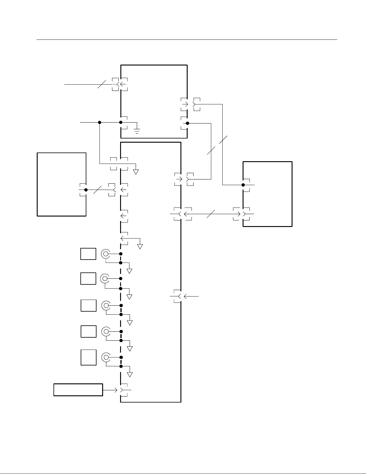
This chapter describes the electrical operation of the TDS1000B and TDS2000B
series oscilloscopes to the module level. It describes the basic operation of each
functional circuit block shown in Figures 3--1 and 3--2. Of necessity, the
descriptions for the two and four channel units, and the color and monochrome
units, are slightly different.
TDS1000B and TDS2000B Series Oscilloscope Service Manual
3--1

Theory of Operation
AC Line
Power Supply
3
AC Line In
P3
Backlight Power
Through
chassis
Front Panel
J1
CH1
CH2
P53
12
Probe Comp
Signal
Probe Comp
GND
J300
J350
GND
J202
P/O J2031
P/O J2032
A1 Main
GND
USB Device
DC Out
&Line
Trigger
DC In
LCD
18 Pins
J902
port
J101
J201
P131
11
(Color)
16
PC or printer
2
(Mono)
12
TDS1000B (Mono)
TDS2000B (Color)
Display
J90
1
Backlight
J902
Display Control
J380
EXT
TRIG
J901
Your USB Flash drive
USB Flash
Drive port
Figure 3--1: Module-level block diagram (two channel)
3--2
TDS1000B and TDS2000B Series Oscilloscope Service Manual
AC Line
Theory of Operation
Power Supply
3
AC Line In
P3
Backlight Power
Through
chassis
Front Panel
J1
CH1
CH2
CH3
12
Probe Comp
Signal
Probe Comp
GND
GND
A1 Main
GND
J202
J104 P/O J2031
J104 P/O J2032
J300
J350
J600
USB Device
DC Out
Trigger
DC In
LCD
18 Pins
J1202
port
&Line
J101
J201
2
11
16
PC or printer
Color Display
J90
1
Backlight
J902
Display Control
CH4
EXT
TRIG
Your USB Flash drive
J650
J680
J1201
USB Flash
Drive port
Figure 3--2: Module-level block diagram (four channel)
TDS1000B and TDS2000B Series Oscilloscope Service Manual
3--3

Theory of Operation
Main Board
The Main board is also called the acquisition board. The Main board of the
four-channel oscilloscopes is essentially 2, two-channel oscilloscopes tied
together through a common microprocessor, and some special interconnects to
support combining the display and trigger systems. For this reason, the focus of
the main board discussion will be the two-channel system, with differences noted
as necessary.
At a minimum, the main board contains attenuators, an amplifier ASIC, a
digitizer/trigger system ASIC, a signal processing/display/system services ASIC,
RAM, flash PROM, a system microprocessor, USB controller, USB RAM,
system communication RAM, and special power supplies. For a four-channel
oscilloscope, the attenuators and ASICs are duplicated. Most of the other aspects
of the circuitry remain unchanged.
Acquisition System
Signals from the CH 1, CH 2 and other input connectors pass through attenuators
and an AC-coupling switch to the amplifier ASIC. The EXT TRIG input has an
abbreviated version of this path, lacking some of the attenuator settings and the
AC coupling switch.
The amplifier ASIC contains buffers and variable gain amplifiers, as well as
filters that provide 20 MHz bandwidth limiting. The task of the amplifier ASIC is
to convert from a 1 MΩ single-ended environment in the front end to a much
lower impedance differential (and thus less noise-sensitive) environment for the
acquisition process. The amplifier ASIC assures that the input signal is amplified
to approximately the correct level to allow the fullest possible use of the digitizer.
The acquisition ASIC contains samplers and peak detectors for each input
channel, a common amplifier, an A/D converter, and the trigger logic. The
digitized waveform samples are transferred to the processing and display ASIC.
In four-channel systems, the two acquisition ASICs are interconnected so that a
trigger on one ASIC can cause a trigger on the other.
The processor system adds the microprocessor and flash PROM to the processing
and display system. The processor system interprets the front-panel control
changes detected by the display ASIC, provides control parameters based upon
user setting requests, computes waveform measurements, and manages the USB
interfaces via the dedicated USB controller. Saved setups, waveforms, and
calibration constants are stored in nonvolatile memory sections within the flash
PROM. The processor system shares DRAM with the display system.
3--4
TDS1000B and TDS2000B Series Oscilloscope Service Manual

Theory of Operation
Processing and Display
System
Input Signal Interface
The processing and display system consists of the display ASIC, DRAM, and
system oscillator. Digitized acquisition samples are received by the display ASIC
and stored in DRAM. Once data are received by the display ASIC, various
corrections are applied, display rasterization is performed, and the waveform is
placed into a display buffer. At the same time, the waveform is being read from
the display buffers and written to the LCD. Additional circuitry in the display
ASIC supports scanning the front panel, handling DRAM refresh, providing the
processor clock, and performing various memory mapping tasks required by all
elementary microprocessor based systems. In a four-channel system, the two
display ASICs are interconnected so that one ASIC may provide display
information for the second.
The processing and display system handles some of the computational tasks.
Other tasks are performed by the processor system. Since all array processing is
performed in the processing and display system, no computations can be
performed that involve data from two different channel sets. Thus, subtracting
channel 3 data from channel 2 is prohibited. Channel 1 and Channel 2 data may
be combined in all of the supported ways.
BNC connectors are mounted on the main board for all signal inputs. The signal
inputs are compatible with the supplied P2220 probes.
Probe Compensation
External Trigger
Main Board Power
The PROBE COMP and ground terminals are provided for probe adjustment.
The EXT TRIG channel is processed on the chain containing the highest
numbered normal input channel.
To support various functions on the main board, a number of secondary power
supplies are generated. For the amplifier and acquisition ASICs, the main board
creates a +2.5 V and --2.5 V supply. The +2.5 V supply is derived from the
+3.3 V logic supply. The --2.5 V supply is derived from the --4 V supply. One
three terminal regulator provides +5 V for internal uses. A second three terminal
regulator provides USB power to preclude USB faults from seriously disrupting
operation of the oscilloscope.
An additional power supply provides the LCD bias voltage which ranges from
+19 V to +28 V, depending on contrast setting and display type. This +28 V
supply has a temperature sensor on the front-panel board that varies the output
voltage of the supply to maintain contrast over a wide temperature range.
TDS1000B and TDS2000B Series Oscilloscope Service Manual
3--5

Theory of Operation
Power Supply
Display Module
The main power supply module for the TDS1000B and TDS2000B series
oscilloscopes is a wide input range universal supply. It is capable of providing
about 25 W of power for the oscilloscope while allowing the input to run from
about 90 V to 264 V. Input frequency ranges from 47 Hz to 440 Hz, which allows
operation in virtually all countries in the world and in a number of off-grid
environments, such as power on military aircraft.
The secondary supplies from the power supply and the approximate current
draws are listed in the table on page 6--25 with the associated connector pins on
J101.
For information on voltages used in the oscilloscope, refer to the Troubleshooting
section of this manual.
Front Panel
Two-Channel
Oscilloscopes
The display module is a standard passive liquid crystal display (LCD). The
monochrome unit is patterned with 320 columns by 240 rows, and has the
associated drivers and backlight. The color unit is patterned with 320 columns x
3 sub-columns by 240 rows and has the associated drivers and backlight. In both
displays, the backlight tube is in a 5mA top lamp configuration.
You can manipulate all of the switches, and position encoders on the front-panel
board of two-channel oscilloscopes. Several LEDs are used to indicate when the
Multipurpose knob is active, when Autorange is active, and when a Save action
is in progress. For more information on the LEDs, refer to the User Manual for
your oscilloscope.
Additionally, an IC on the front-panel board provides buffering and multiplexing
of switch signals to the main board. Two signals and a sense line are provided by
the main board to support the front panel. One of these lines resets the scan; a
second clocks the scan to the next position; and the sense line receives the current
state of the selected switch or encoder position.
For the encoders, some amount of debouncing occurs inside the front-panel IC.
All key debouncing is handled in the display ASIC on the main board.
3--6
The LEDs are controlled by latching the value of the Channel 1--2 front panel
scan counter when the appropriate scan value is set.
TDS1000B and TDS2000B Series Oscilloscope Service Manual

Theory of Operation
Four-Channel
Oscilloscopes
The front-panel board of the four channel units is effectively two panels in
parallel. The left side of the board is largely handled by the display ASIC for
channels 1 and 2. The right side of the board is handled by the channel 3 and 4
ASIC. Separate front-panel ICs support these data paths.
TDS1000B and TDS2000B Series Oscilloscope Service Manual
3--7

Theory of Operation
3--8
TDS1000B and TDS2000B Series Oscilloscope Service Manual

Performance Verification


Performance Verification
c
OscilloscopeCalibration
This chapter contains performance verification procedures for the specifications
marked with the n symbol. The following equipment, or a suitable equivalent,
is required to complete these procedures.
Required Equipment
Description
DC Voltage Source 17.5mVto7V,±0.5%
Leveled Sine Wave Generator 50 kHz and 200 MHz, ±3%
Time Mark Generator 10 ms period, ±10 ppm
Minimum
requirements
accuracy
amplitude accuracy
accuracy
Examples
Wavetek 9100 Universal
Calibration System with
Os
illoscopeCalibration
Module (Option 250)
Fluke 5500A Multi-product
Calibrator with Oscilloscope
Calibration Option (Option
5500A-SC)
50 Ω BNC Cable BNCmaletoBNCmale,
≈ 1 m (36 in) long
50 Ω BNC Cable BNCmaletoBNCmale,
≈ 25 cm (10 in) long
50 Ω Feedthrough
Termination
Dual Banana to BNC Adapter Banana plugs to BNC female Tektronix part number
BNC T Adapter BNC male to dual BNC
Splitter, Power Frequency range: DC to
Adapter (four required) Male N-- to--female BNC Tektronix part number
Adapter Female N-- to--male BNC Tektronix part number
Leads, 3 Black Stacking Banana Plug Patch
Leads, 2 Red Stacking Banana Plug Patch
BNC male and female
connectors
female connectors
4 GHz. Tracking: >2.0%
Cord, ≈ 45 cm (18 in) long
Cord, ≈ 45 cm (18 in) long
Tektronix part number
012-0482-XX
Tektronix part number
012-0208-XX
Tektronix part number
011-0049-XX
103-0090-XX
Tektronix part number
103-0030-XX
Tektronix part number
015-0565-XX
103-045-XX
103-0058-XX
Pomona #B-18-0
Pomona #B-18-2
TDS1000B and TDS2000B Series Oscilloscope Service Manual
4- 1

Performance Verification
Test Record
Model
number
Serial
number
Procedure performed by Date
Test Passed Failed
1. Self Test
2. Self Calibration
3. Oscilloscope tests
Oscilloscope tests Low limit Test result High limit
Channel 1 DC Gain Accuracy 5mV/div 33.6 mV 36.4 mV
200 mV/div 1.358 V 1.442 V
2V/div 13.58 V 14.42 V
Channel 2 DC Gain Accuracy 5mV/div 33.6 mV 36.4 mV
200 mV/div 1.358 V 1.442 V
2V/div 13.58 V 14.42 V
Channel 3 DC Gain Accuracy15mV/div 33.6 mV 36.4 mV
200 mV/div 1.358 V 1.442 V
2V/div 13.58 V 14.42 V
Channel 4 DC Gain Accuracy15mV/div 33.6 mV 36.4 mV
200 mV/div 1.358 V 1.442 V
2V/div 13.58 V 14.42 V
Channel 1 Bandwidth 2.12 V —
Channel 2 Bandwidth 2.12 V —
Channel 3 Bandwidth
Channel 4 Bandwidth
1
1
2.12 V —
2.12 V —
2
2
2
2
Sample Rate and Delay Time Accuracy -- 2 d i v s +2 divs
Channel 1 Edge Trigger Sensitivity Stable trigger —
Channel 2 Edge Trigger Sensitivity Stable trigger —
Channel 3 Edge Trigger Sensitivity
Channel 4 Edge Trigger Sensitivity
1
1
Stable trigger —
Stable trigger —
External Edge Trigger Sensitivity Stable trigger —
3
3
3
3
3
4- 2
TDS1000B and TDS2000B Series Oscilloscope Service Manual
Performance Verification
Oscilloscope tests High limitTest resultLow limit
Channel 1 Vertical Position Accuracy, Minimum margin 0 —
Channel 2 Vertical Position Accuracy, Minimum margin 0 —
Channel 3 Vertical Position Accuracy1, Minimum margin 0 —
Channel 4 Vertical Position Accuracy1, Minimum margin 0 —
1
Channels 3 and 4 are only available on four channel oscilloscopes.
2
The bandwidth test does not have a high limit.
3
The limits vary by model. Check the procedure for the correct limits.
Performance Verification Procedures
Before beginning these procedures, two conditions must first be met:
H The oscilloscope must have been operating continuously for twenty minutes
within the operating temperature range specified.
Self Test
Self Calibration
H You must perform the Self Calibration operation described below. If the
ambient temperature changes by more than 5 °C, you must perform the Self
Calibration operation again.
The time required to complete the entire procedure is approximately one hour.
WARNING. Some procedures use hazardous voltages. To prevent electrical shock,
always set voltage source outputs to 0 V before making or changing any
interconnections.
This internal procedure is automatically performed every time the oscilloscope is
powered on. No test equipment or hookups are required. Verify that no error
messages are displayed before continuing with this procedure.
The self calibration routine lets you quickly optimize the oscilloscope signal path
for maximum measurement accuracy. You can run the routine at any time, but
you should always run the routine if the ambient temperature changes by 5 _Cor
more.
1. Disconnect any probes or cables from the channel input connectors (CH 1,
CH 2, CH 3, CH 4).
2. Push the UTILITY button and select the Do Self Cal option to start the
routine. The routine takes approximately one minute to complete.
TDS1000B and TDS2000B Series Oscilloscope Service Manual
4- 3
Performance Verification
3. Verify that self calibration passed.
Check DC Gain Accuracy
This test checks the DC gain accuracy of all input channels.
1. Set the DC voltage source output level to 0V.
2. Set up the oscilloscope using the following steps:
Push menu button Select menu option Select setting
1. DEFAULT SETUP — —
2. CH 1 Probe 1X
3. ACQUIRE Average 16
4. MEASURE
Source Channel under test
Type Mean
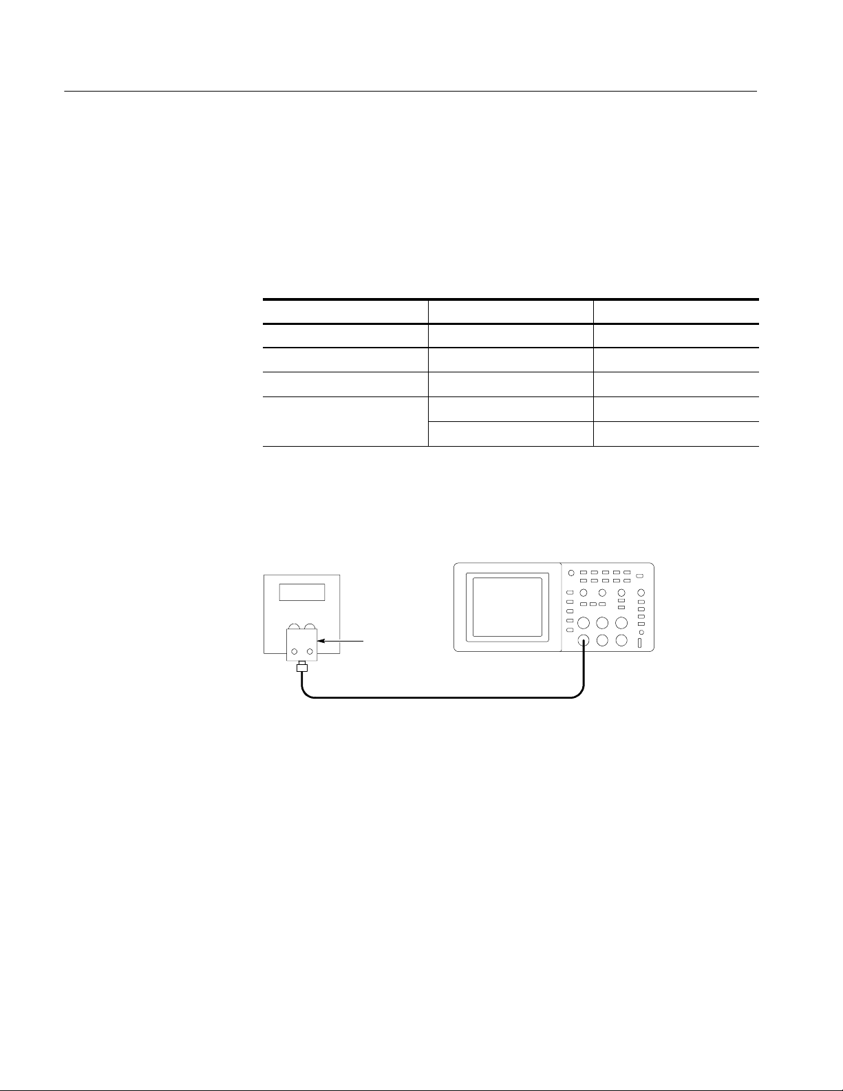
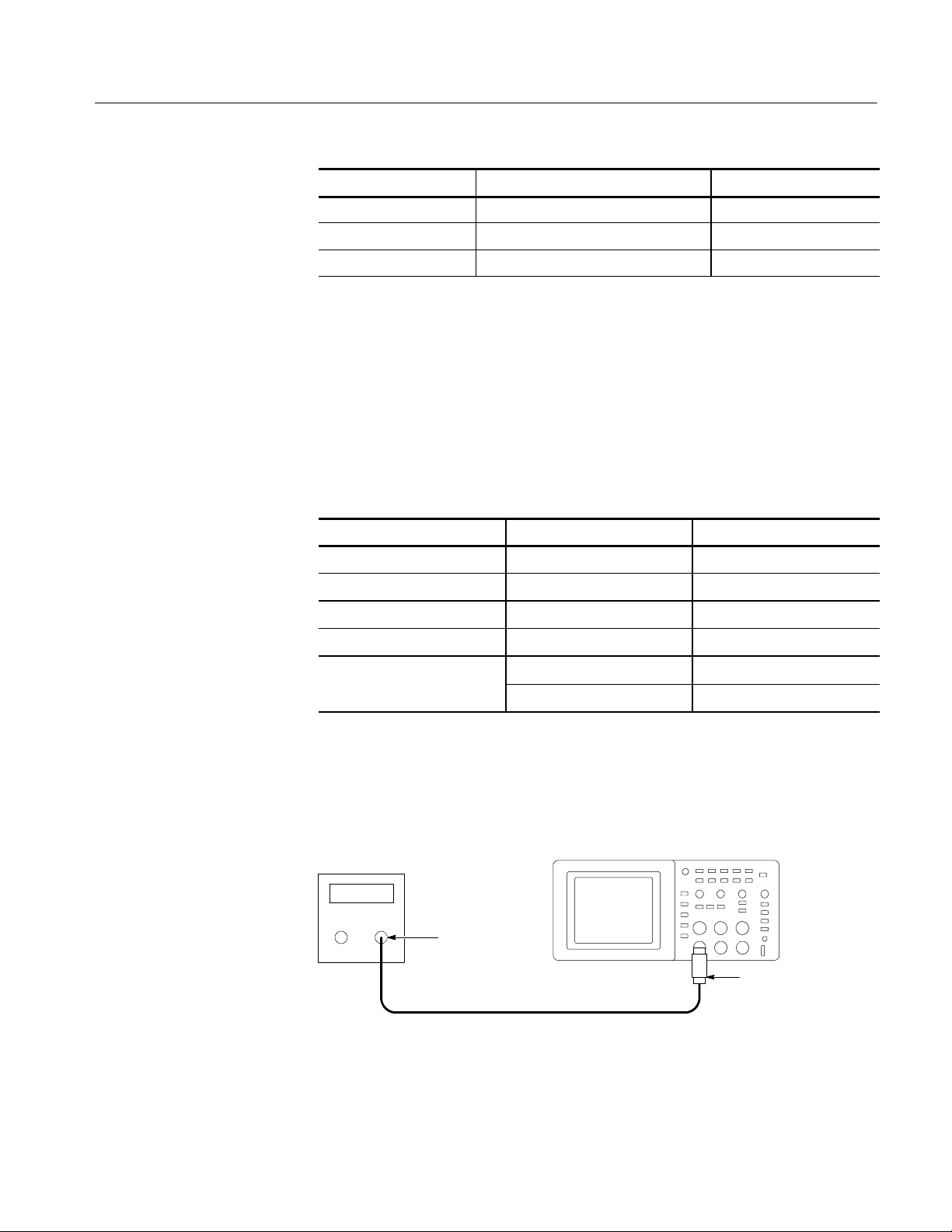
3. As shown below, connect the oscilloscope channel selected in the table to the
DC voltage source.
DC voltage
source
Digitizing oscilloscope
+--
Dual banana
to BNC
adapter
BNC cable
4. For each VOL TS/DIV setting listed below, perform the following steps:
a. Set the DC voltage source output level to the positive voltage listed and
then record the mean measurement as V
pos
.
b. Reverse the polarity of the DC voltage source and then record the mean
measurement as V
c. Calculate V
diff=Vpos
neg
.
-- V
and then compare V
neg
to the accuracy
diff
limits in the table.
4- 4
TDS1000B and TDS2000B Series Oscilloscope Service Manual
Performance Verification
Check Bandwidth
VOLTS/DIV setting DC voltage source output levels Accuracy limits for V
5mV/div +17.5 mV, --17.5 mV 33.6 mV to 36.4 mV
200 mV/div +700 mV, --700 mV 1.358 V to 1.442 V
2V/div +7.00 V, --7.00 V 13.58 V to 14.42 V
5. Set DC voltage source output level to 0V.
6. Disconnect the test setup.
7. Repeat steps 1 through 6 until all input channels have been checked.
This test checks the bandwidth of all input channels.
1. Set up the oscilloscope using the following steps:
Push menu button Select menu option Select setting
DEFAULT SETUP — —
CH 1 Probe 1X
ACQUIRE Average 16
diff
TRIGGER Coupling Noise Reject
MEASURE
Source Channel under test
Type Pk-Pk
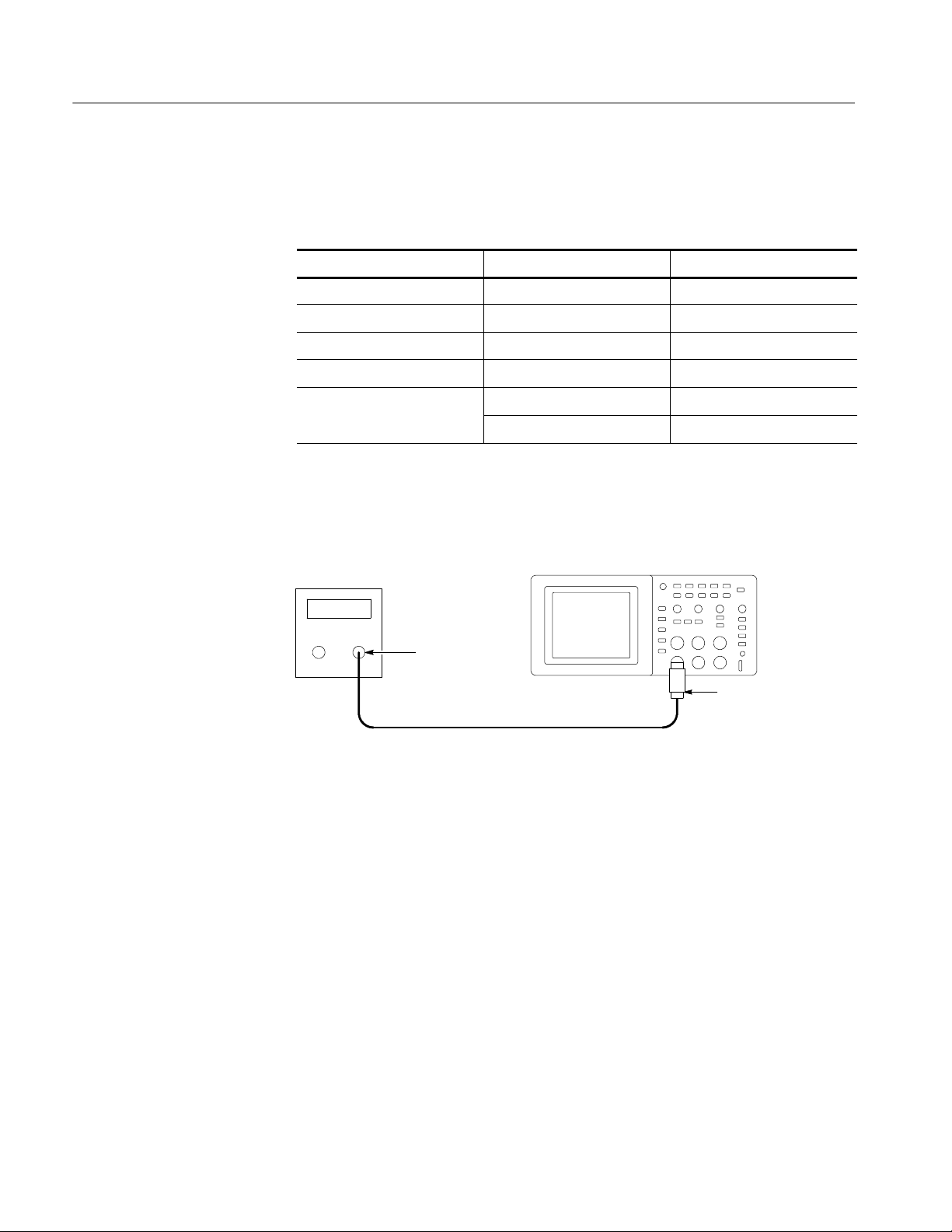
2. As shown below, connect the oscilloscope channel selected in the table to the
leveled sine wave generator.
Leveled
sine wave
generator
Output
BNC cable
Digitizing oscilloscope
50 Ω feedthrough
terminator
3. Set the oscilloscope VOLTS/DIV to 500 mV/div.
4. Set the oscilloscope SEC/DIV to 10 s/div.
TDS1000B and TDS2000B Series Oscilloscope Service Manual
4- 5

Performance Verification
5. Set the leveled sine wave generator frequency to 50 kHz.
6. Set the leveled sine wave generator output level so the peak-to-peak
measurement is between 2.98 V and 3.02 V.
7. Set the leveled sine wave generator frequency to:
H 40 MHz if you are checking a TDS1001B
H 60 MHz if you are checking a TDS1002B, TDS2002B, or TDS2004B
H 100 MHz if you are checking a TDS1012B, TDS2012B, or TDS2014B
H 200 MHz if you are checking a TDS2022B, or TDS2024B
8. Set the oscilloscope SEC/DIV to 10 ns/div.
9. Check that the peak-to-peak measurement is ≥2.12 V.
10. Disconnect the test setup.
11. Repeat steps 1 through 10 until all input channels have been checked.
Check Sample Rate
Accuracy and Delay Time
Accuracy
This test checks the time base accuracy.
1. Set up the oscilloscope using the following steps:
Push menu button Select menu option Select setting
DEFAULT SETUP — —
CH 1 Probe 1X
2. Connect the oscilloscope to the time mark generator as shown below.
Time mark
generator
Output
BNC cable
Digitizing oscilloscope
50 Ω feedthrough
terminator
4- 6
3. Set the time mark generator period to 10 ms.
4. Set the oscilloscope VOLTS/DIV to 500 mV/div.
TDS1000B and TDS2000B Series Oscilloscope Service Manual

Performance Verification
5. Set the oscilloscope Main SEC/DIV to 1ms/div.
6. Push SET TO 50%.
7. Use the vertical POSITION control to center the test signal on screen.
8. Use the horizontal POSITION control to set the position to 10.00 ms.
9. Set the oscilloscope SEC/DIV to 250 ns/div.
10. Check that the rising edge of the marker crosses the center horizontal
graticule line within ±2 divisions of the vertical center graticule line.
Vertical center
graticule line
Horizontal center
graticule line
Acceptable limits
NOTE. One division of displacement from graticule center corresponds to
a 25 ppm time base error.
11. Disconnect the test setup.
TDS1000B and TDS2000B Series Oscilloscope Service Manual
4- 7
Performance Verification
Check Edge Trigger
Sensitivity
This test checks the edge trigger sensitivity for all input channels.
1. Set up the oscilloscope using the following steps:
Push menu button Select menu option Select setting
DEFAULT SETUP — —
CH 1 Probe 1X
TRIGGER Mode Normal
ACQUIRE Sample —
MEASURE
Source Channel under test
Type Pk-Pk
2. As shown below, connect the oscilloscope channel selected in the table to the
leveled sine wave generator.
Leveled sine
wave generator
Digitizing oscilloscope
Output
50 Ω feedthrough
BNC cable
terminator
3. Set the oscilloscope VOLTS/DIV to 500 mV/div.
4. Set the oscilloscope SEC/DIV to 25 ns/div.
5. Set the leveled sine wave generator frequency to 10 MHz.
6. Set the leveled sine wave generator output level to approximately 500 mV
so that the measured amplitude is approximately 500 mV. (The measured
amplitude can fluctuate around 500 mV.)
7. Push SET TO 50%. Adjust TRIGGER LEVEL as necessary and then
check that triggering is stable.
8. Set the leveled sine wave generator frequency to:
H 40 MHz if you are checking a TDS1001B
H 60 MHz if you are checking a TDS1002B, TDS2002B, or TDS2004B
p-p
4- 8
TDS1000B and TDS2000B Series Oscilloscope Service Manual

Performance Verification
H 100 MHz if you are checking a TDS1012B, TDS2012B, TDS2014B,
TDS2022B, or TDS2024B
9. Set the oscilloscope SEC/DIV to 5ns/div.
10. Set the leveled sine wave generator output level to approximately 750 mV
so that the measured amplitude is approximately 750 mV. (The measured
amplitude can fluctuate around 750 mV.)
11. Push SET TO 50%. Adjust TRIGGER LEVEL as necessary and then
check that triggering is stable.
12. For the TDS2022B and TDS2024B models, set the frequency to 200 MHz,
and increase the amplitude to 1 Vp--p. Verify stable triggering.
13. Set the oscilloscope SEC/DIV to 2.5 ns/div.
14. Change the oscilloscope setup using the following step:
Push menu button Select menu option Select setting
TRIGGER Slope Falling
15. Push SET TO 50%. Adjust TRIGGER LEVEL as necessary and then
check that triggering is stable.
16. Disconnect the test setup.
17. Repeat steps 1 through 16 until all input channels have been checked.
p-p
Check External Edge
Trigger Sensitivity
This test checks the edge trigger sensitivity for the external trigger.
1. Set up the oscilloscope using the following steps:
Push menu button Select menu option Select setting
DEFAULT SETUP — —
CH 1 Probe 1X
TRIGGER
ACQUIRE Sample —
MEASURE
Source Ext
Mode Normal
Source CH1
Type Pk-Pk
TDS1000B and TDS2000B Series Oscilloscope Service Manual
4- 9
Performance Verification
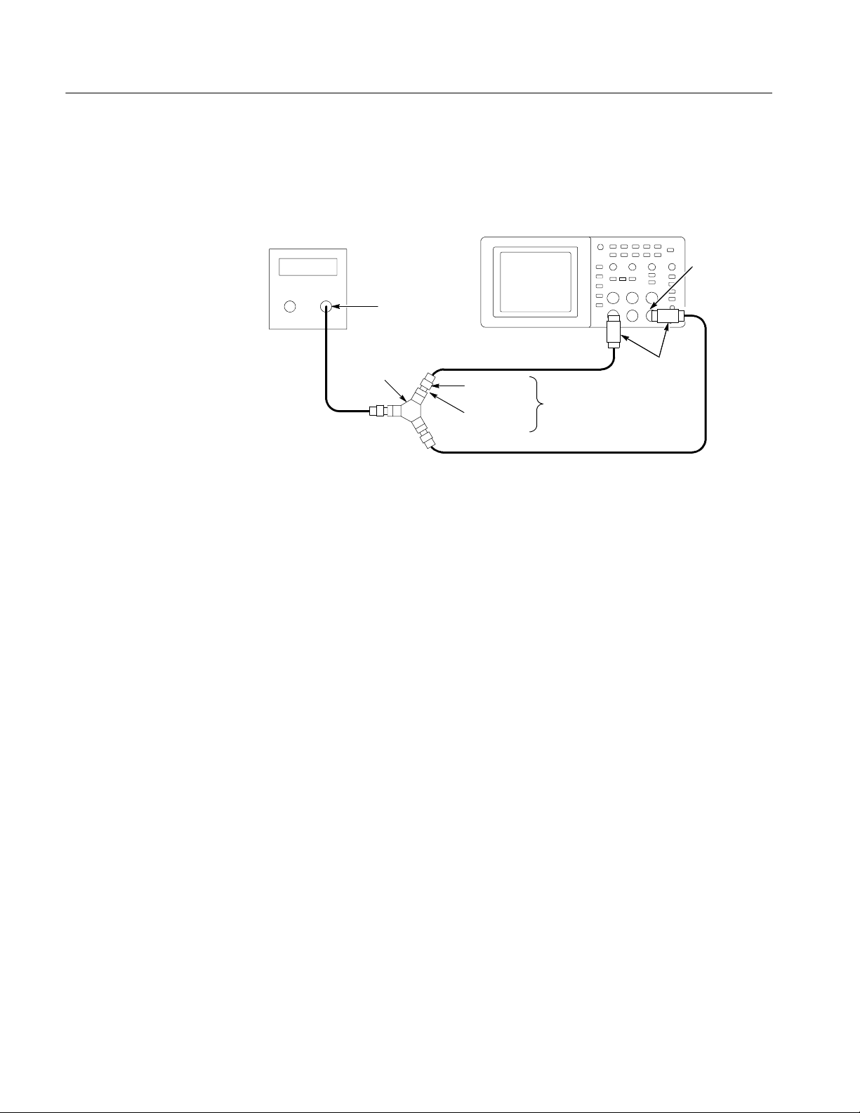
2. Connect the oscilloscope to the leveled sine wave generator as shown below
usingCH1andEXTTRIG.
Leveled sine
wave generator
Output
Power divider
Male SMA to
female BNC
SMA female-to--female
Digitizing oscilloscope
3Pieces
50 Ω
feedthrough
terminator
3. Set the oscilloscope VOLTS/DIV to 100 mV/div.
4. Set the oscilloscope SEC/DIV to 25 ns/div.
5. Set the leveled sine wave generator frequency to 10 MHz.
6. Set the sine wave generator output level to approximately 300 mV
the power splitter. This will be about 200 mV
on CH1 of the oscilloscope.
p-p
EXT TRIG
into
p-p
The EXT TRIG input will also be receiving approximately 200 mV
deviations from the nominal 200 mV
oscilloscope display are acceptable.
p--p
. Small
p-p
7. Set the leveled sine wave generator frequency to:
H 40 MHz if you are checking a TDS1001B
H 60 MHz if you are checking a TDS1002B, TDS2002B, or TDS2004B
H 100 MHz if you are checking a TDS1012B, TDS2012B, TDS2014B,
TDS2022B, or TDS2024B
8. Set the oscilloscope SEC/DIV to 5ns/div.
9. Push SET TO 50%. Adjust TRIGGER LEVEL as necessary and then
check that triggering is stable.
10. For TDS2022B and TDS2024B models, set the sine wave generator output
level for a CH 1 display to approximately 350 mV
p-p
.
11. For TDS2022B and TDS2024B models, set the sine wave generator
frequency to 200 MHz.
4- 10
TDS1000B and TDS2000B Series Oscilloscope Service Manual

Performance Verification
12. Set the oscilloscope SEC/DIV to 2.5 ns/div.
13. Push SET TO 50%. Adjust TRIGGER LEVEL as necessary and then
check that triggering is stable.
14. Change the oscilloscope setup using the following step:
Push menu button Select menu option Select setting
TRIGGER Slope Falling
15. Push SET TO 50%. Adjust TRIGGER LEVEL as necessary and then
check that triggering is stable.
16. Disconnect the test setup.
Check Vertical Position
Accuracy
The results of this test and the DC Gain Accuracy test together define the DC
Measurement Accuracy of the oscilloscope. The DC Measurement Accuracy
specification encompasses two different ranges of operation over two different
attenuator settings:
H DC Gain Accuracy: Identifies errors, mostly from the A/D converter, when
the vertical position (known as offset in these oscilloscopes) is set to 0
divisions (or a grounded input will show screen center)
H Vertical Position Accuracy: Identifies errors, mostly from the position
control, made when the vertical position is set to a non--zero value
The two attenuator settings operate identically, so verification of the attenuation
range from --1.8 V to 1.8 V also verifies the attenuation range of --45 V to 45 V.
To set up the test, follow these steps:
1. Set up the oscilloscope as shown in the next table.
Push menu button Select menu option Select setting
DEFAULT SETUP — —
CH 1, CH 2, CH 3, CH 4 Probe 1X
CH 1, CH 2, CH 3, CH 4 Volts/Div 50 mV/div
TRIGGER
ACQUIRE Sample —
Source Ext*
Mode Auto
TDS1000B and TDS2000B Series Oscilloscope Service Manual
4- 11

Performance Verification
Push menu button Select settingSelect menu option
MEASURE
*
The test operates without a trigger. To maintain uniformity and to avoid false
triggering on noise, the Ext trigger is the recommended source.
Source Channel under test
Type Mean
2. Make a spreadsheet approximately as shown in the example in Appendix A.
You only need to enter the values for column A and the equations. The
values in columns B, C, D, E, F, and G are examples of the measured or
calculated values.
The PDF version of the TDS1000B and TDS2000B service manual (which
you can download from the www.tektronix.com Web site), includes an
empty spreadsheet for your convenience. To access and save the test
spreadsheet, see the instructions in Appendix A: Example of a Vertical
Position Accuracy Test Spreadsheet on page A--1.
3. Connect the oscilloscope, power supply and voltmeter as shown next.
Oscilloscope under test
BNC-to-Dual
Banana adapter
Power supply
Negative
Red leads
Black leads
Voltmeter
4. Set the power supply to the 1.8 V value shown in column A, the Approximate Test Voltage.
5. Adjust the vertical position knob for the DC line to position the line in the
center of the screen.
4- 12
6. Enter the voltage on the voltmeter and on the oscilloscope into the spreadsheet in the appropriate columns, B and C.
7. Repeat steps 4 through 6 for the values of 1.76 V through 0 V.
TDS1000B and TDS2000B Series Oscilloscope Service Manual

Performance Verification
8. Swap the connections to the positive terminal of the power supply with those
at the negative terminal as shown next.
Oscilloscope under test
BNC-to-Dual
Banana adapter
Power supply
Positive
Red leads
Black leads
Voltmeter
9. Repeat steps 4 through 6 for the values of --0.04 V through --1.8 V.
10. Enter the Minimum Margin number (cell I16) for the channel tested in the
test record.
11. Repeat steps 1 through 10 until all input channels have been checked.
Data Verification. To verify data, set the spreadsheet to present a line graph of
columns D, E, and F. Verify that no error values (the blue line in the center) go
above the yellow line (upper line), or below the purple line (lower line). For
calculations involved in this example, refer to the data in the previous table.
TDS1000B and TDS2000B Series Oscilloscope Service Manual
4- 13

Performance Verification
Measured
Error
Measured Position
Figure 4- 1: Example of a line graph for the Vertical Position Accuracy test
Error
Lower limit
Upper limit
4- 14
TDS1000B and TDS2000B Series Oscilloscope Service Manual

Adjustment Procedures


Adjustment Procedures
This chapter contains adjustment procedures for the TDS1000B and TDS2000B
series oscilloscopes.
Only qualified personnel should perform service procedures. Read the Service
Safety Summary and the General Safety Summary at the beginning of this manual
before performing any service procedures. Also refer to the user manual for
information about using the TDS1000B and TDS2000B oscilloscopes.
NOTE. The voltage references inside the TDS1000B and TDS2000B oscilloscopes
are very stable over time and should not require routine updates. Before
performing any procedure in this chapter, first verify that the oscilloscope does
not meet specifications. Refer to the chapter Performance Verification to verify
the specifications.
Required Equipment
The equipment described in Table 5--1, or a suitable equivalent, is required to
complete these procedures.
Table 5--1: Required equipment
Description Minimum requirements Examples
DC Voltage Source -- 2 0 V t o 2 0 V, ±0.1% accuracy Wavetek 9100 Universal Calibration
System with Oscilloscope
Calibration Module (Option 250)
Leveled Sinewave
Generator
50 Ω BNC Cable
50 Ω BNC Cable (seven)
50 Ω Feedthrough
Termination
5 kHz and 200 MHz, ±0.6%
amplitude accuracy
BNCmaletoBNCmale,
≈ 1 m (36 in) long
BNCmaletoBNCmale,
≈ 25 cm (10 in) long
BNC male and female
connectors
Fluke 5500A Multi-product
Calibrator with Oscilloscope
Calibration Option
(Option 5500A-SC)
Tektronix part number 012-0482-XX
Tektronix part number 012-0208-XX
Tektronix part number 011-0049-XX
TDS1000B and TDS2000B Series Oscilloscope Service Manual
5--1

Adjustment Procedures
Table 5--1: Required equipment (Cont.)
Description ExamplesMinimum requirements
Dual Banana to BNC
Adapter
Banana plugs to BNC female Tektronix part number 103-0090-XX
Adjustment Procedure
BNC T (three) One male and two female
BNC connectors
Tektronix part number 103-0030-XX
The adjustment procedure consists of 70 steps for the two-channel oscilloscope,
and 106 steps for the four-channel model. Each step requires an external voltage
source for new calibration constants.
Before performing the adjustment procedure, warm up the oscilloscope for at
least ten minutes in an ambient temperature between 20 °C and 30 °C. Adjustments performed prior to warm-up or outside this temperature range may result
in poor performance.
If all steps in the procedure are completed successfully, a “Pass” message is
displayed and the new calibration constants take affect. If any step fails, the
procedure is aborted and the current calibration is not affected. You can choose to
abort the procedure at any step, without affecting the current calibration, by
selecting FCAL ABORT.
NOTE. While performing the adjustment procedure, keep in mind that some of the
steps take a significant amount of time (up to 5 minutes) to complete.
Enable the Service Menu
5--2
The equipment setups, shown in Figure 5--1, are required to complete the
adjustment procedure. Table 5--2 on page 5--6 lists the steps in the procedure
and the signal requirement for each step.
You must enable the Service menu to perform the adjustment procedure. To do
this:
1. Power on the oscilloscope.
2. Push the front-panel MEASURE button to access the MEASURE menu.
3. Push the top option button to access the Measure 1 menu.
4. Push and hold the front-panel SINGLE SEQ button.
5. Push and hold the front-panel AUTOSET button.
6. Wait at least two seconds.
TDS1000B and TDS2000B Series Oscilloscope Service Manual

Adjustment Procedures
7. Release the SINGLE SEQ button.
8. Release the AUTOSET button. A message appears in the lower left corner of
the screen stating “Service mode ON.”
9. Push the front-panel UTILITY button. The last item in the Utility menu is
now “Service.”
At completion of the Adjust procedure disable the “Service” menu through the
UTILITY front panel button, the “Service” option button, and the “Service”
Mode Off” option button.
TDS1000B and TDS2000B Series Oscilloscope Service Manual
5--3

Adjustment Procedures
DC voltage setup 1
DC voltage source
+--
Dual banana to
BNC adapter
10-inch BNC cable
10-inch BNC cable
Two Channel
Digitizing oscilloscope
10-inch
BNC cables
BNC ‘T’ connector
Four Channel
Digitizing oscilloscope
10-inch
BNC cables
10-inch
BNC cable
BNC ‘T’
connector
10-inch BNC cable
10-inch
BNC cables
BNC ‘T’
connectors
DC voltage setup 2
Sinewave generator setup
Leveled sine
wave generator
Output
50 Ω feedthrough terminator
(Table 5--2 and 5--3 list
DC voltage source
+--
Two Channel
Digitizing oscilloscope
proper channel)
Dual banana to
BNC adapter
Two Channel
Digitizing oscilloscope
1 M BNC cable
Edge setup
Square wave
generator
Four Channel
Digitizing oscilloscope
Output
50 Ω feedthrough terminator
(Table 5--2 and 5--3 list
proper channel)
1 M BNC cable
Figure 5--1: Adjustment setups
5--4
1 M BNC cable
TDS1000B and TDS2000B Series Oscilloscope Service Manual

Adjustment Procedures
Adjustment Procedure
Use this procedure to load new calibration constants.
1. Enable the Service menu as described on page 5--2.
2. Push the Service option button.
3. Push the Factory Cal option button.
4. Push the Warmup Timer option button.
5. Push the Start Timer option button to ensure a 10-minute warm up. After 10
minutes pass, the oscilloscope displays a large black or green cross.
6. Press the front-panel UTILITY button and push the Service option button.
7. Push the Factory Cal option button.
8. Push the FCAL INIT option button to initiate the factory calibration routine.
You are now in step 1 of the procedure.
9. As indicated by Step 1 in Table 5--2, connect a 0.0 V
source to the channel
DC
inputs.
10. Press FCAL STEP to load the calibration constant for step 1.
11. Follow the screen prompts along with Table 5--2 for the remainder of the
routine, applying the proper signal for each step.
NOTE. During some steps, the oscilloscope may appear to be idle for several
minutes while it is processing information internally. You must wait for the screen
prompt to continue.
If any step in the procedure fails, the procedure terminates. Failure will result
if an incorrect signal source is connected. If this happens, you must start the
procedure over from the beginning.
If the procedure completes successfully, a “Pass” message is displayed and
the new adjustment takes effect.
12. Compensate the signal path by performing the self-calibration routine.
Disconnect any probes or cables from the channel input connectors. Then,
press the UTILITY button and select Do Self Cal to confirm that you are
ready to proceed.
13. Disable the Service menu option by pushing the UTILITY front-panel
button, and the Service and Service Mode Off option buttons.
TDS1000B and TDS2000B Series Oscilloscope Service Manual
5--5

Adjustment Procedures
g
Table 5--2: Adjustment steps
Step number
(Two-channel
models)
Refer to the DC voltage setup 1 diagram
1 1 DC Voltage 1 0.0 V
2 2 DC Voltage 1 --20.0 V
3 3 DC Voltage 1 -- 2 . 0 V
4 4 DC Voltage 1 -- 1 . 6 V
5 5 DC Voltage 1 -- 1 . 2 V
6 6 DC Voltage 1 -- 0 . 8 V
7 7 DC Voltage 1 -- 0 . 4 V
8 8 DC Voltage 1 --0.32 V
9 9 DC Voltage 1 -- 0 . 2 V
10 10 DC Voltage 1 --0.16 V
11 11 DC Voltage 1 --0.08 V
12 12 DC Voltage 1 --0.04 V
13 13 DC Voltage 1 --0.03 V
14 14 DC Voltage 1 --0.02 V
15 15 DC Voltage 1 --0.015 V
16 16 DC Voltage 1 0.015 V
17 17 DC Voltage 1 0.02 V
18 18 DC Voltage 1 0.03 V
19 19 DC Voltage 1 0.04 V
20 20 DC Voltage 1 0.08 V
21 21 DC Voltage 1 0.16 V
22 22 DC Voltage 1 0.2 V
23 23 DC Voltage 1 0.32 V
24 24 DC Voltage 1 0.4 V
25 25 DC Voltage 1 0.8 V
26 26 DC Voltage 1 1.2 V
27 27 DC Voltage 1 1.6 V
28 28 DC Voltage 1 2.0 V
29 29 DC Voltage 1 20.0 V
30 30 DC Voltage 1 0.0 V
Step number
(Four-channel
models)
Signal Signal source setting Input
CH1 through
CHx
5--6
TDS1000B and TDS2000B Series Oscilloscope Service Manual

Table 5--2: Adjustment steps (Cont.)
S
i
O
hmBWL
V
5050SinewaveGenerator,50OhmBW
L,2.5
V
p-p
5151SinewaveGenerator,50OhmBW
L,5
V
p-p
Adjustment Procedures
Step number
(Two-channel
models)
Step number
(Four-channel
models)
Refer to the DC voltage setup 2 diagram
31 31 DC Voltage 2 -- 5 . 0 V
32 32 DC Voltage 2 -- 1 . 0 V
33 33 DC Voltage 2 1.0 V
34 34 DC Voltage 2 5.0 V
Refer to the Sinewave generator setup diagram. BWL refers to the maximum bandwidth of the oscilloscope.
35 35 Sinewave Generator, 50 Ohm 5 kHz, 1 V
36 36 Sinewave Generator, 50 Ohm 1 MHz, 100 mV
37 37 Sinewave Generator, 50 Ohm 1MHz,1V
38 38 Sinewave Generator, 50 Ohm 50 kHz, 1 V
39 39 Sinewave Generator, 50 Ohm 20 MHz, 1 V
40 40
newaveGenerator, 50
41 41 Sinewave Generator, 50 Ohm BWL, 50 mV
42 42 Sinewave Generator, 50 Ohm BWL, 100 mV
43 43 Sinewave Generator, 50 Ohm BWL, 250 mV
44 44 Sinewave Generator, 50 Ohm BWL, 500 mV
45 40 Sinewave Generator, 50 Ohm BWL, 1 V
46 46 Sinewave Generator, 50 Ohm 5 kHz, 2.5 V
47 47 Sinewave Generator, 50 Ohm 1MHz,2.5V
48 48 Sinewave Generator, 50 Ohm 50 kHz, 2.5 V
49 49 Sinewave Generator, 50 Ohm 20 MHz, 2.5 V
,25m
p-p
p-p
p-p
p-p
p-p
p-p
p-p
p-p
p-p
p-p
p-p
p-p
p-p
p-p
p-p
InputSignal source settingSignal
EXT TRIG
CH1
52 52 Sinewave Generator, 50 Ohm BWL, 1.6 V
53 53 Edge, 50 Ohm. Refer to Edge setup
1 kHz, 0 to --800 mV
p-p
diagram.
TDS1000B and TDS2000B Series Oscilloscope Service Manual
5--7

Adjustment Procedures
S
i
O
hmBWL
V
6969SinewaveGenerator,50OhmBW
L,2.5
V
p-p
7070SinewaveGenerator,50OhmBW
L,5
V
p-p
Table 5--2: Adjustment steps (Cont.)
Step number
(Two-channel
models)
54 54 Sinewave Generator, 50 Ohm 5 kHz, 1 V
Step number
(Four-channel
models)
p-p
55 55 Sinewave Generator, 50 Ohm 1 MHz, 100 mV
56 56 Sinewave Generator, 50 Ohm 1MHz,1V
57 57 Sinewave Generator, 50 Ohm 50 kHz, 1 V
58 58 Sinewave Generator, 50 Ohm 20 MHz, 1 V
59 59
newaveGenerator, 50
60 60 Sinewave Generator, 50 Ohm BWL, 50 mV
,25m
p-p
p-p
p-p
p-p
p-p
61 61 Sinewave Generator, 50 Ohm BWL, 100 mV
62 62 Sinewave Generator, 50 Ohm BWL, 250 mV
63 63 Sinewave Generator, 50 Ohm BWL, 500 mV
64 64 Sinewave Generator, 50 Ohm BWL, 1 V
65 65 Sinewave Generator, 50 Ohm 5 kHz, 2.5 V
66 66 Sinewave Generator, 50 Ohm 1MHz,2.5V
p-p
p-p
p-p
67 67 Sinewave Generator, 50 Ohm 50 kHz, 2.5 V
68 68 Sinewave Generator, 50 Ohm 20 MHz, 2.5 V
InputSignal source settingSignal
CH2
p-p
p-p
p-p
p-p
p-p
p-p
5--8
TDS1000B and TDS2000B Series Oscilloscope Service Manual

Table 5--2: Adjustment steps (Cont.)
S
i
O
hmBWL
V
86SinewaveGenerator,50OhmBW
L,2.5
V
p-p
87SinewaveGenerator,50OhmBW
L,5
V
p-p
Adjustment Procedures
Step number
(Two-channel
models)
NA
Step number
(Four-channel
models)
71 Sinewave Generator, 50 Ohm 5 kHz, 1 V
p-p
72 Sinewave Generator, 50 Ohm 1 MHz, 100 mV
73 Sinewave Generator, 50 Ohm 1MHz,1V
74 Sinewave Generator, 50 Ohm 50 kHz, 1 V
75 Sinewave Generator, 50 Ohm 20 MHz, 1 V
76
newaveGenerator, 50
77 Sinewave Generator, 50 Ohm BWL, 50 mV
,25m
p-p
p-p
p-p
p-p
p-p
78 Sinewave Generator, 50 Ohm BWL, 100 mV
79 Sinewave Generator, 50 Ohm BWL, 250 mV
80 Sinewave Generator, 50 Ohm BWL, 500 mV
81 Sinewave Generator, 50 Ohm BWL, 1 V
82 Sinewave Generator, 50 Ohm 5 kHz, 2.5 V
83 Sinewave Generator, 50 Ohm 1MHz,2.5V
p-p
p-p
p-p
84 Sinewave Generator, 50 Ohm 50 kHz, 2.5 V
85 Sinewave Generator, 50 Ohm 20 MHz, 2.5 V
InputSignal source settingSignal
CH3
p-p
p-p
p-p
p-p
p-p
p-p
88 Sinewave Generator, 50 Ohm BWL, 1.6 V
89 Edge, 50 Ohm. Refer to the Edge
1 kHz, 0 to --800 mV
setup diagram.
p-p
TDS1000B and TDS2000B Series Oscilloscope Service Manual
5--9

Adjustment Procedures
S
i
O
hmBWL
V
W
L
V
p-p
105SinewaveGenerato
r,50OhmBW
L,2.5
V
p-p
W
L,5V
p-p
106SinewaveGenerato
r,50OhmBW
L,5
V
p-p
Table 5--2: Adjustment steps (Cont.)
Step number
(Two-channel
models)
NA
Step number
(Four-channel
models)
90 Sinewave Generator, 50 Ohm 5 kHz, 1 V
p-p
91 Sinewave Generator, 50 Ohm 1 MHz, 100 mV
92 Sinewave Generator, 50 Ohm 1MHz,1V
93 Sinewave Generator, 50 Ohm 50 kHz, 1 V
94 Sinewave Generator, 50 Ohm 20 MHz, 1 V
95
newaveGenerator, 50
96 Sinewave Generator, 50 Ohm BWL, 50 mV
,25m
p-p
p-p
p-p
p-p
p-p
97 Sinewave Generator, 50 Ohm BWL, 100 mV
98 Sinewave Generator, 50 Ohm BWL, 250 mV
99 Sinewave Generator, 50 Ohm BWL, 500 mV
100 Sinewave Generator, 50 Ohm BWL, 1 V
101 Sinewave Generator, 50 Ohm 5 kHz, 2.5 V
102 Sinewave Generator, 50 Ohm 1MHz,2.5V
p-p
p-p
p-p
103 Sinewave Generator, 50 Ohm 50 kHz, 2.5 V
InputSignal source settingSignal
CH4
p-p
p-p
p-p
p-p
p-p
104 Sinewave Generator, 50 Ohm 20 MHz, 2.5 V
105 Sinewave Generator, 50 Ohm B
,2.5
106 Sinewave Generator, 50 Ohm B
p-p
5--10
TDS1000B and TDS2000B Series Oscilloscope Service Manual

Maintenance


Maintenance
Preventing ESD
This chapter contains the information needed to do periodic and corrective
maintenance on the oscilloscope, as well as repackaging instructions if you need
to return the oscilloscope to Tektronix for service.
Before servicing this product, read the Safety Summary and Introduction at the
front of the manual and the electrostatic discharge (ESD) information below.
CAUTION. Static discharge can damage any semiconductor component in this
oscilloscope.
When performing any service which requires internal access to the oscilloscope,
adhere to the following precautions. These precautions help you avoid damaging
internal modules and their components due to electrostatic discharge (ESD).
H Minimize handling of static-sensitive modules.
H Transport and store static-sensitive modules in their static protected
containers or on a metal rail. Label any package that contains static-sensitive
modules.
H Discharge the static voltage from your body by wearing a grounded antistatic
wrist strap while handling these modules.
H Service static-sensitive modules only at static-free workstations. Do not
allow anything capable of generating or holding a static charge on the
workstation surface.
H Handle circuit boards by the edges when possible.
H Do not slide the modules over any surface.
H Avoid handling modules in areas that have a floor or work-surface covering
capable of generating a static charge.
TDS1000B and TDS2000B Series Oscilloscope Service Manual
6--1

Maintenance
Inspection and Cleaning
Inspection and cleaning are done as preventive maintenance. Preventive
maintenance, when done regularly, may prevent oscilloscope malfunction and
enhance its reliability.
Preventive maintenance consists of visually inspecting and cleaning the
oscilloscope, and using general care when operating it. How often you do
maintenance depends on the severity of the environment in which you use the
oscilloscope. A good time to perform preventive maintenance is just before
adjustment of the oscilloscope.
General Care
Interior Cleaning
For optimum performance, follow these recommendations:
H Protect the oscilloscope from adverse weather conditions. The oscilloscope is
not waterproof.
H Do not store or leave the oscilloscope where the liquid crystal display (LCD)
will be exposed to direct sunlight or high humidity for long periods of time.
H The front and rear cases help keep dust out of the oscilloscope and must be in
place during normal operation.
H To avoid damage to the oscilloscope or probes, do not expose them to any
sprays, liquids, or solvents.
Use a dry, low-velocity stream of air to clean the interior of the chassis. Use a
soft-bristle, non-static-producing brush for cleaning around components. If you
must use a liquid for minor interior cleaning, use a 75% isopropyl alcohol
solution and rinse with deionized water.
WARNING. To avoid injury, power down the instrument and disconnect it from
line voltage before performing any procedure that follows.
6--2
Exterior Cleaning
Clean the exterior surfaces of the chassis with a dry lint-free cloth or a softbristle brush. If any dirt remains, use a cloth or swab dipped in a 75% isopropyl
alcohol solution. Use a swab to clean narrow spaces around controls and
connectors. Do not use abrasive compounds on any part of the chassis that may
damage the chassis.
Clean the On/Standby switch using a dampened cleaning towel. Do not spray or
wet the switch directly.
TDS1000B and TDS2000B Series Oscilloscope Service Manual

Maintenance
CAUTION. Avoid the use of chemical cleaning agents, which might damage the
plastics used in this oscilloscope. Use only deionized water when cleaning the
menu buttons or front-panel buttons. Use a 75% isopropyl alcohol solution as a
cleaner and rinse with deionized water. Before using any other type of cleaner,
consult your Tektronix Service Center or representative.
Exterior Inspection
Inspect the outside of the oscilloscope for damage, wear, and missing parts, using
Table 6--1 as a guide. Immediately repair defects that could cause personal injury
or lead to further damage to the oscilloscope.
Table 6--1: External inspection check list
Item Inspect for Repair action
Front and rear case Cracks, scratches, deformations,
damaged hardware
Front-panel knobs Missing, damaged, or loose
knobs
Connectors Broken shells, cracked insulation,
and deformed contacts. Dirt in
connectors
Carrying handle, and
cabinet feet
Accessories Missing items or parts of items,
Correct operation Repair or replace defective
bent pins, broken or frayed
cables, and damaged connectors
Repair or replace defective
module
Repair or replace missing or
defective knobs
Repair or replace defective
modules. Clear or wash out dirt.
module
Repair or replace damaged or
missing items, frayed cables, and
defective modules
If the display is very dirty, moisten the wipe with distilled water or a 75%
isopropyl alcohol solution and gently rub the display surface. Avoid using excess
force or you may damage the plastic display surface.
CAUTION. To prevent getting moisture inside the oscilloscope during external
cleaning, use only enough liquid to dampen the cloth or applicator.
TDS1000B and TDS2000B Series Oscilloscope Service Manual
6--3

Maintenance
Interior Inspection
To access the inside of the oscilloscope for inspection and cleaning, refer to the
Removal Procedures in this section.
Use Table 6--2 as a guide to inspect the internal portions of the oscilloscope for
damage and wear. Repair any defects immediately.
If any circuit board is repaired or replaced, check Table 6--2 to see if it is
necessary to adjust the oscilloscope.
CAUTION. To prevent damage from electrical arcing, ensure that circuit boards
and components are dry before applying power to the oscilloscope.
Table 6--2: Internal inspection check list
Item Inspect for Repair action
Circuit boards Loose, broken, or corroded solder
connections. Burned circuit
boards. Burned, broken, or
cracked circuit-run plating.
Resistors Burned, cracked, broken, blis-
tered condition.
Solder connections Cold solder or rosin joints. Resolder joint and clean with
Remove and replace damaged
circuit board.
Remove and replace damaged
circuit board.
isopropyl alcohol.
Capacitors Damaged or leaking cases.
Corroded solder on leads or
terminals.
Wiring and cables Loose plugs or connectors.
Burned, broken, or frayed wiring.
Chassis Dents, deformations, and dam-
aged hardware.
Remove and replace damaged
circuit board.
Firmly seat connectors. Repair or
replace modules with defective
wires or cables.
Straighten, repair, or replace
defective hardware.
Cleaning Procedure, Interior. To clean the oscilloscope interior, perform the
following steps:
1. Blow off dust with dry, low-pressure, deionized air (approximately 9 psi).
2. Remove any remaining dust with a lint-free cloth dampened in isopropyl
alcohol (75% solution) and then wipe with a lint-free cloth dampened with
warm deionized water. A cotton-tipped applicator is useful for cleaning in
narrow spaces and on circuit boards.
6--4
TDS1000B and TDS2000B Series Oscilloscope Service Manual

Maintenance
STOP. If, after performing steps 1 and 2, a module is clean upon inspection, skip
steps 3, 4, and 5. Proceed with step 6.
3. If steps 1 and 2 do not remove all the dust or dirt, all modules in the
oscilloscope except the Display Module and Front Panel Module may be
spray washed using a solution of 75% isopropyl alcohol.
H During cleaning of the Acquisition board (main board), use care to
assure that no residue is left in the attenuators. Debris or residue can
cause a number of problems with signal fidelity that cannot be corrected
by calibration. When handling the board, avoid handling the attenuators
since skin oils may cause problems.
H Extensive cleaning of the Display Module is difficult because water must
not be trapped between the display shield and the display. The polarizers
integrated into the display degrade with long-term exposure to water. The
display shield and display must be replaced as an assembly if significant
moisture or debris become trapped inside. Cotton tipped applicators and
lint-free rags moistened in isopropyl alcohol and/or deionized water offer
the best cleaning with the least opportunity for damage to the assembly.
H The Front Panel module can be damaged by deposition of film or debris
inside the knob encoders. To avoid this, care must be taken to not drip
liquid or blow debris into the encoders.
4. Spray wash dirty parts with the 75% isopropyl alcohol solution and wait 60
seconds for the majority of the alcohol to evaporate.
5. Use hot (49 _Cto60_C / 120 _F to 140 _F) deionized water to thoroughly
rinse the parts.
6. Dry all parts with low-pressure, deionized air.
7. Dry all components and assemblies in an oven or drying compartment using
low-temperature (52 _Cto66_C / 125 _F to 150 _F) circulating air.
Lubrication. Periodic lubrication is not required for the oscilloscope.
TDS1000B and TDS2000B Series Oscilloscope Service Manual
6--5
Maintenance
Removal and Installation Procedures
Refer to Figures 6--1 and 6--2 for the location of modules that you are removing
or installing. If you are disassembling the instrument for cleaning, refer to the
Inspection and Cleaning procedure on page 6--2 for instructions.
List of Modules
Summary of Procedures
The Replaceable Parts List provides a list of all replaceable modules. Any
replaceable component, assembly, or part is referred to by the term module.
WARNING. Only qualified personnel should perform service procedures. Before
doing this or any other procedure in this manual, read the General Safety
Summary and Service Safety Summary found at the beginning of this manual. To
prevent damage to electrical components, read Preventing ESD on page 6-- 1.
Always disconnect the power cord before disassembling any portion of the
oscilloscope.
Complete disassembly is best achieved by following the procedures in the order
given in Table 6--3.
Table 6--3: List of procedures
Procedure Begins on page
Rear Feet 6--8
Flip Feet 6--8
6--6
Front-Panel Knobs and Power Button 6--9
Rear Case 6--9
Front Feet 6--10
Power Supply Module 6--11
Internal Assembly 6--12
Display Cable 6--12
Front-Panel Cable 6--14
Main Board Module 6--15
Color Display Module 6--16
Monochrome Display Module 6--16
Front-Panel Module 6--18
Keypad 6--18
Front Case 6--19
TDS1000B and TDS2000B Series Oscilloscope Service Manual

Front Case
assembly
Maintenance
Power button
Rear case
Rear foot
Front foot
Figure 6--1: Locator for trim and cabinet removal
Display
assembly
Switch keypad
Power supply
assembly
Front panel assembly
Front flip foot
Main board
assembly
Chassis assembly
Figure 6--2: Locator for internal modules
TDS1000B and TDS2000B Series Oscilloscope Service Manual
6--7

Maintenance
Required Tools
Rear Feet
Use the following tools to remove and replace all modules in the oscilloscope:
H Torque-limiting screwdriver, long shank, 12 in-lb (1.3 N
⋅m) range with
Torx® T-15 tip; if you use a magnetic screwdriver with interchangeable bits,
the T--15 bit must be a long bit, at least 5 cm (2 in) overall length
H Torque-limiting screwdriver with Torx T--8 bit
H 5/8 inch deep socket with wide center hole (S
⋅K Hand Tool Corp., S-K
#40820, or equivalent)
H Torque wrench to 40 in-lb (4.5 N
⋅m)
H Screwdriver with 1/4 inch flat blade
H Pliers (all-purpose and needle-nose)
H Sharp knife (X-ACTO
® knife or equivalent)
H 3M Electrical Tape 92 with 1--mil polyimide Kapton backing, temperature
rated 180 °C, UL510 Flame Retarded
You will need a flat-blade screwdriver to remove the rear feet.
Flip Feet
Removal. To remove the rear feet, refer to Figure 8--4 and follow these steps:
1. Place the oscilloscope face down on a soft surface such as an anti-static mat.
2. Use a flat-blade screwdriver to pry out the foot, or twist the foot as you are
removing it so that it disengages from the guides. Use care not to mar the
surface of the rear case.
Installation. To install the rear feet, refer to Figure 8--4 and follow these steps:
1. Place the oscilloscope face down on a soft surface such as an anti-static mat.
2. Align the slots of the rear foot with the guides in the rear case and press the
foot in.
You will need a pair of needle-nose pliers to remove the flip feet.
Removal. To remove the flip feet, refer to Figure 8--4 and follow these steps:
1. Place the oscilloscope face down on a soft surface such as an anti-static mat.
2. Grip the flip foot with the pliers as close to the notches as possible and
squeeze gently on the foot.
6--8
3. Twist slightly to swing one hinge free of the slot.
TDS1000B and TDS2000B Series Oscilloscope Service Manual

Maintenance
Installation. To install the flip feet, refer to Figure 8--4, and follow these steps:
1. Place the oscilloscope face down on a soft surface such as an anti-static mat.
2. Hold the flip foot with the smooth side facing down.
3. Gently squeeze the foot so that the hinge on one side fits into the slot, and
twist slightly to snap into the slot on the other side.
Front-Panel Knobs
Power Button
Rear Case
Remove each front-panel knob by firmly grasping the knob (with pliers if
necessary) and pulling it away from the front panel.
NOTE. Wrap the plier jaws with tape (such as electrical) to avoid marring the
knob surface.
Install front-panel knobs by aligning the keyed knob with the shaft and pressing
the knob onto the shaft.
Remove the power button by firmly grasping the button with pliers, and pull it
straight out of the cabinet.
NOTE. Wrap the plier jaws with tape (such as electrical) to avoid marring the
button surface.
Install the button by pressing it onto the power button shaft until it snaps into
place.
You will need a torque-limiting Torx T-15 screwdriver and pliers for this
procedure.
Removal. To remove the rear case, refer to Figure 8--4, and follow these steps:
1. Remove the power button using the procedure on page 6--9.
2. Place the oscilloscope face down on a soft surface such as an anti-static mat.
3. Remove the five screws located on the rear case. Tilt the handle to gain better
access to the top two screws.
4. Lift the rear case off of the oscilloscope.
TDS1000B and TDS2000B Series Oscilloscope Service Manual
6--9

Maintenance
Installation. Use this procedure to install the rear case.
1. Place the oscilloscope face down on a soft surface (such as an anti-static
mat).
2. Place the rear case onto the assembled oscilloscope and ensure that:
H All of the edges align with the front case.
H The Li--ION battery is vertical in the battery location.
H The slots align near the USB connector and near the battery.
CAUTION. Be careful not to pinch any wires or other parts between the front and
rear cases.
3. Install the five screws in the rear case. Tilt the handle to better access the top
two holes.
Front Feet
CAUTION. Avoid cross threading the screws that secure the rear case to the front
case. An easy way to avoid this is to slip the screw into the hole and, using slight
pressure, slowly rotate the screw counterclockwise until you feel the screw slip
into the screw threads. Then tighten the screw clockwise. A properly s tarted
screw will have very little resistance going in.
4. Install the power button as described on page 6--9.
You will need a torque-limiting Torx T-15 screwdriver and pliers for this
procedure.
Removal. First, remove the power button and rear case using the procedures on
page 6--9. Then, slide the front feet out of the front case as shown in Figure 8--1
for 2-channel models, or Figure 8--2 for 4-channel models.
Installation. Slide the feet into the slots provided in the front case as shown in
Figure 8--1 for 2-channel models, or Figure 8--2 for 4-channel models. Use the
installation procedures for each module removed to reassemble the oscilloscope.
NOTE. If the front feet are not installed, but are available, they can be inserted by
carefully pinching them and pushing them into their slots. For example, you may
need to do this if the rear case has been removed, and a foot has been rubbed off
and unnoticed until the case is being reassembled.
6--10
TDS1000B and TDS2000B Series Oscilloscope Service Manual

Maintenance
Power Supply Module
Use a torque-limiting Torx T-15 screwdriver and pliers for this procedure.
Removal. To remove the module, refer to Figure 8--3 and follow these steps:
1. Remove the power button and rear case using the procedures on page 6-- 9.
2. Disconnect the following wires:
H The ground wire on the power supply module from the chassis ground
lug.
H The two-conductor backlight cable on the power supply module.
H The power supply cable on the main board at J101. Press down on the
latch while pulling up on the cable.
3. Remove the five screws connecting the power supply module to the chassis
and lift the module from the internal assembly.
Installation. To install the power supply module, refer to Figure 8--3 and follow
these steps:
1. Align and place the power supply module into the internal assembly.
2. Install the two longer screws with thread lock into the IEC connector
mounting holes.
3. Install the three shorter screws through the power supply and into the chassis.
4. Reconnect the following wire and cables:
H The ground wire on the power supply module to the chassis ground lug.
You may need to use pliers to secure the wire in place.
H The two-conductor backlight cable to the power supply module.
H The power supply cable to the main board at J101. Twist the cable to
keep it from contact with the boards and chassis.
NOTE. Wind up the power supply cable until it is tight; loops are okay. This keeps
the cable bundle together.
5. Use the installation procedure for each module removed to reassemble the
oscilloscope.
TDS1000B and TDS2000B Series Oscilloscope Service Manual
6--11

Maintenance
Internal Assembly
You will need a torque-limiting Torx T-15 screwdriver and a pair of pliers for this
procedure.
Removal. To remove the internal assembly, refer to Figure 8--4 and follow these
steps:
1. Remove the front-panel knobs, power button, and rear case using the
procedures on page 6--9.
2. Remove the five screws attaching the internal assembly to the front case.
3. Lift the entire internal assembly (consisting of the chassis, all of the boards,
and the display screen) out of the front case.
NOTE. The switch keypad will most likely remain inside the front case. It does not
need to be removed with the internal assembly.
Installation. To install the internal assembly, refer to Figure 8--4 and follow these
steps:
1. Use the installation procedure for each module removed to reassemble the
oscilloscope.
Display Cable
2. Install the switch mat in the front case.
3. Place the internal assembly into the front case.
4. Install the five screws to attach the internal assembly to the front case.
You will need a torque-limiting Torx T-15 screwdriver and pliers for this
procedure.
Removal. To remove the display cable, refer to Figure 8--3 and follow these steps:
1. Remove the power button and rear case using the procedures on page 6-- 9.
2. Remove the power supply using the procedure on page 6--11.
3. Disconnect the display cable at J201 on the main board by pulling straight up
from the connector.
4. Remove the cable tie, and remove the tape to release the display cable.
6--12
TDS1000B and TDS2000B Series Oscilloscope Service Manual

Maintenance
5. Remove the display.
6. Disconnect the display cable on the display module.
7. Thread the cable out of the chassis.
Installation. To install the display cable, refer to Figure 8--3 and follow these
steps:
1. Remove the display module using the procedure on page 6--16.
2. Attach the display cable to the appropriate connector on the display module
at the location shown in Figure 8--3: 12-pin for the monochrome display, and
15-pin for the color display.
3. With the display module in place but not connected, thread the display cable
through the appropriate slot on the chassis.
4. Twist the cable to keep it from contact with the boards and chassis.
NOTE. Wind up the display cable until it is tight; loops are okay. This keeps the
cable bundle together.
5. Connect the display cable at J201 on the main board by pushing the cable
straight down into the connector.
6. Secure the display cable to the chassis with the cable tie.
7. Apply 3 strips of 3M Electrical Tape 92 to secure the cable to the chassis.
Figure 6--3 shows where to apply the tape for good results.
TDS1000B and TDS2000B Series Oscilloscope Service Manual
6--13

Maintenance
Twist the
display cable
Addacabletie
Tape the cable
to the chassis
Front-Panel Cable
Figure 6--3: Securing the display cable to the chassis
8. Install the four screws to attach the display module to the internal assembly.
You will need a torque-limiting Torx T-15 screwdriver and pliers for this
procedure.
Removal. To remove the front-panel cable, refer to Figure 8--3 and follow these
steps:
1. Remove the front-panel knobs, power button, and rear case using the
procedures on page 6--9.
2. Remove the internal assembly using the procedure on page 6--12.
3. Remove the five screws attaching the front panel board to the chassis.
4. Untwist the cable tie to release the front-panel cable.
5. Disconnect the front-panel cable at J202 on the main board by pulling
straight up from the connector.
6. Disconnect the front-panel cable at J1 on the front-panel module.
6--14
TDS1000B and TDS2000B Series Oscilloscope Service Manual

Maintenance
Installation. To install the front-panel cable, refer to Figure 8--3 and follow these
steps:
1. Connect the front-panel cable to the front-panel module at J1 through the
appropriate slot on the chassis.
2. Twist the cable to keep it from contact with the boards and chassis, and
secure using the right cable tie.
NOTE. Wind up the front-panel cable until it is tight; loops are okay. This keeps
the cable bundle together.
3. Connect the front-panel cable at J202 on the main board by pushing the cable
straight down into the connector.
4. Install the five screws to attach the front panel module to the chassis.
Main Board Module
You will need a torque-limiting Torx T-15 long shank screwdriver, a torque
wrench, and a 5/8 inch deep socket for this procedure.
CAUTION. The main board module is particularly sensitive to ESD. Read the
Preventing ESD section on page 6--1 before removing or installing the main
board.
Removal. To remove the main board module, refer to Figure 8--3 and follow
these steps:
1. Remove the power button and rear case using the procedures on page 6-- 9.
2. Remove the internal assembly from the front case using the procedure on
page 6--12.
3. Disconnect the following wires from the main board by pulling straight up
from the connector:
H The power supply cable at J101. Press down on the latch while pulling
up on the cable.
H The display cable at J201.
H The front-panel cable at J202.
4. Use the screwdriver to remove the three screws attaching the main board
module to the internal assembly.
5. Use the socket to remove the nuts and washers from the BNC connectors.
TDS1000B and TDS2000B Series Oscilloscope Service Manual
6--15

Maintenance
6. Pull the board out from the front slots of the internal assembly.
Installation. To install the main board module, refer to Figure 8--3 and follow
these steps:
1. Work from the bottom of the internal assembly, and place the front of the
main board module into the slots on the internal assembly near the the BNC
connectors.
2. Use the deep socket to attach the washers and nuts to each BNC connector so
that the main board is securely attached to the chassis.
Support the BNC to prevent it from twisting the main board, and torque the
nuts to 40 in-lbs (4.5 N⋅m) using the torque wrench.
3. Install the three screws attaching the main board module to the internal
assembly.
4. Reconnect the following wires on the main board:
Display Module
H The power supply cable at J101.
H The display cable at J201.
H The front-panel cable at J202.
5. Use the installation procedure for each module removed to reassemble the
oscilloscope.
You will need a torque-limiting Torx T-15 screwdriver, a torque-limiting Torx
T-8 screwdriver, and pliers for this procedure.
Removal. To remove the display module, refer to Figure 8--1 for 2-channel
models or Figure 8--2 for 4-channel models, and follow these steps:
1. Remove the power button and rear case using the procedures on page 6-- 9.
2. Remove the internal assembly from the front case using the procedure on
page 6--12.
3. Disconnect the backlight cable from the power supply module.
4. For color displays, follow these steps:
6--16
a. Remove the power supply module using the procedure on page 6--11.
b. Remove the four screws attaching the display module to the chassis. The
screws were exposed when the power supply module was removed.
TDS1000B and TDS2000B Series Oscilloscope Service Manual

Maintenance
5. For monochrome displays, remove the four screws attaching the display
module to the internal assembly.
6. Disconnect the display cable using the procedure on page 6--12.
NOTE. Be careful that you do not loosen the mounting posts from the chassis. If
the mounting posts should become loosened, it will be necessary to remove the
power supply module to access the screws at the other end of the post.
CAUTION. The display shield is attached to the display module. Removing the
shield will destroy the attaching gasket.
Installation. To install the display module, refer to Figure 8--1 for 2-channel
models or Figure 8--2 for 4-channel models, and follow these steps:
1. Reconnect the display cable at J201 on the main board by pushing the cable
straight down into the connector.
2. Route the display cable through the opening in the chassis. For more
information, see the display cable procedure on page 6--12.
3. For color displays, use the Torx T-8 screwdriver and install the four screws to
attach the display module to the chassis. Torque the nuts to 3 in-lbs
(0.33 N⋅m) using the torque wrench (2.864 +/-- .26 in--lbs).
For 2-channel models, the location and type of screws shown in Figure 8--1
will vary between the color and monochrome displays.
4. For monochrome displays, install the four screws to attach the display
module to the internal assembly.
5. Install the power supply module using the procedure on page 6--11.
6. Route the backlight cable through the opening in the internal assembly.
7. Reconnect the backlight cable to the power supply module.
Connect to the black socket for a monochrome display, and to the white
socket for a color display.
8. Reconnect the display cable using the installation procedure on page 6--13.
9. Use the installation procedure for each module removed to reassemble the
oscilloscope.
TDS1000B and TDS2000B Series Oscilloscope Service Manual
6--17

Maintenance
Front-Panel Module
You will need a torque-limiting Torx T-15 screwdriver and a flat-blade screwdriver for this procedure.
Removal. To remove the front-panel module, refer to Figure 8--1 for 2-channel
models or Figure 8--2 for 4-channel models, and follow these steps:
1. Remove the power button and rear case using the procedures on pages 6-- 9.
2. Remove the entire internal assembly from the front case using the procedure
on page 6--12.
3. Disconnect the front-panel cable at J202 on the main board by pulling
straight up from the connector.
4. Remove the five screws attaching the front-panel module to the internal
assembly.
5. Pull the module away from the internal assembly.
Installation. To install the front-panel module, refer to Figure 8--1 for 2-channel
models or Figure 8--2 for 4-channel models, and follow these steps:
1. Reconnect the front-panel cable at J202 on the main board by pushing the
cable straight down into the connector.
Keypad
2. Route the front-panel cable through the opening in the internal assembly. For
more information, see the procedure on page 6--14.
3. Install the five screws to attach the front-panel module to the internal
assembly.
4. Use the installation procedure for each module removed to reassemble the
oscilloscope.
You will need a torque-limiting Torx T-15 screwdriver for this procedure.
Removal. To remove the switch keypad, refer to Figure 8--1 for 2-channel models
or Figure 8--2 for 4-channel models, and follow these steps:
1. Remove the power button and rear case using the procedures on page 6-- 9.
2. Remove the entire internal assembly from the front case using the procedure
on page 6--12.
3. Lift the keypad out of the front case.
6--18
TDS1000B and TDS2000B Series Oscilloscope Service Manual
Maintenance
CAUTION. Keep the electrical contacts on the back of the keypad clean. Skin oils
and dust will inhibit good electrical contact.
Installation. To install the switch keypad, refer to Figure 8--1 for 2-channel
models or Figure 8--2 for 4-channel models, and follow these steps:
1. Place the front case face down on a soft surface.
2. Align the switch keypad into the front case using the guide posts and the
holes in the keypad.
CAUTION. Keep the electrical contacts on the back of the switch pad clean. Skin
oils and dust will inhibit good electrical contact.
3. Check that all buttons are properly seated into place before proceeding.
Front Case
4. Place the entire internal assembly into the front case.
5. Use the installation procedure for each module removed to reassemble the
oscilloscope.
You will need a torque-limiting Torx T-15 screwdriver for this procedure.
Removal. To remove the front case, refer to Figure 8--1 for 2-channel models or
Figure 8--2 for 4-channel models, and follow these steps:
1. Remove the power button and rear case using the procedures on page 6-- 9.
2. Remove the entire internal assembly from the front case using the procedure
on page 6--12.
3. Remove the switch keypad using the procedure on page 6--18.
Installation. To install the front case, refer to Figure 8--1 for 2-channel models or
Figure 8--2 for 4-channel models, and follow these steps:
1. Place the switch keypad into the front case.
2. Place the entire internal assembly into the front case.
3. Use the installation procedure for each module removed to reassemble the
oscilloscope.
TDS1000B and TDS2000B Series Oscilloscope Service Manual
6--19

Maintenance
Troubleshooting
This section contains information and procedures to help you isolate a defective
module in the oscilloscope.
WARNING. Before doing this or any other procedure in this manual, read the
General Safety Summary and Service Safety Summary found at the beginning of
this manual. Also, to prevent possible injury or damage to electrical components,
read Preventing ESD on page 6--1.
Adjustment After Repair
Required Tools and
Equipment
If you replace the main board or power supply, you must adjust the oscilloscope
after repair. Refer to the chapter Adjustment Procedures.
You may need the the following tools and equipment to troubleshoot the
oscilloscope:
Tools and equipment Example
Oscilloscope with 1X/10X and 100X probes Tektronix TDS1000B or TDS2000B series
oscilloscope with standard accessory 1X/10X
probe (P2220) and optional 100X probe
(P5100 or P5200)
DMM 3.5 or greater digit DMM
USB flash drive Tektronix part number 119-7276-00, 128 MB
USB type A to type B cable Tektronix part numbers:
174-4401-00, .91 meters (3 feet)
174-5194-00, 1.83 meters (6 feet)
PC with USB host post and with TekVISA
(OpenChoice PC Communications) installed
PC with USB communication port
Troubleshooting Tree
6--20
To isolate a problem to a specific troubleshooting procedure, use the troubleshooting tree in Figures 6--4, 6--5, 6--6 and 6--7. Detailed procedures follow the
tree.
TDS1000B and TDS2000B Series Oscilloscope Service Manual

Maintenance
Put scope or
frequency counter
on probe comp
1 kHz?
Yes
Verify LCD
connector and
cable values
No
Replace main
board
No
Run probe check
on each channel
Turn on power
Does screen
lighten?
Yes
See
boot up
screen?
Yes
Errors?
No
Front panel
problems?
No
No
Yes
Yes
From Figure 6-6
A
To Figure 6-6
B
C
To Figure 6-5
D
To Figure 6-5
No
Yes
Replace display
or display cable
Probe
check Ok?
Yes
Connect
external trigger
to probe comp
Set trigger
source to EXT
Press set 50%
No
Good
voltages?
Replace main
board
Figure 6--4: Oscilloscope troubleshooting tree (1 of 4)
TDS1000B and TDS2000B Series Oscilloscope Service Manual
Replace main
board
Trigger
indicator ON?
Yes
No
Replace main
board
E
To Figure 6-7
6--21
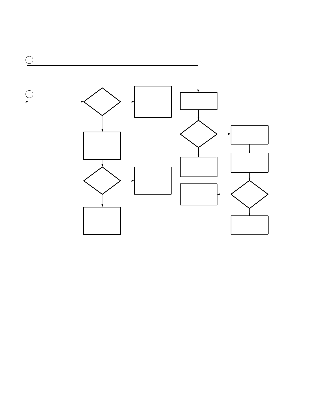
Maintenance
C
From Figure 6-4
D
From Figure 6-4
Able to run
front panel
tests?
Yes
Run front panel
tests in service
menu
<5key
problem
Yes
Replace front
panel board
No
No
Check cabling to
main board.
Replace cable;
front panel or main
board
Check cabling to
main board;
Replace cable or
main board
Verify power
supply voltages
Power
supplies OK?
Yes
Replace main
board
Replace power
supply
No
No
Disconnect
power supply
Verify power
supply Voltages
Power
supplies OK?
Yes
Replace main
board
Figure 6--5: Oscilloscope troubleshooting tree (2 of 4)
6--22
TDS1000B and TDS2000B Series Oscilloscope Service Manual

Maintenance
To Figure 6-4
From Figure 6-4
A
B
Power cord
attached?
Yes
Open case
Fuse OK?
Yes
Backlight cable
attached?
Yes
Using a high
voltage 100X
probe test voltages
on backlight
connectors
No
No
No
Attach power
cord
Reinstall case
Replace power
supply
Attach backlight
cable
~50 kHz
>700 V
Detach display
~50 kHz
>700 V
Replace power
supply
pk--pk
No
pk--pk
No
?
?
Figure 6--6: Oscilloscope troubleshooting tree (3 of 4)
Yes
Yes
Replace display
TDS1000B and TDS2000B Series Oscilloscope Service Manual
6--23

Maintenance
Install a compatible
USB flash drive in
the front--panel port
Does the
flash drive
blink?*
Yes
Examine the
contents of the
flash drive through
the file controls
Does
the data
match what is
visible on the
PC?
Yes
Check that the
TekVISA software
(OpenChoice PC
Communications) is
installed on the PC
Connect the
oscilloscope to
the PC
No
No
E
Replace the
Main board
Does the data
match what is
visible on the
oscilloscope?
From Figure 6-4
No
Yes
Transfer data from
the oscilloscope to
the PC
* The oscilloscope displays a clock symbol when the flash drive is active, and a hint line when a save or recall operation is complete.
Good oscilloscope
Figure 6--7: Oscilloscope troubleshooting tree (4 of 4)
6--24
TDS1000B and TDS2000B Series Oscilloscope Service Manual

Maintenance
PROBE COMP Output
Troubleshooting the
Power Supply
When the oscilloscope is on and operating properly, the PROBE COMP output
should generate a square wave, approximately 5 V in amplitude, at a 1 kHz
frequency. Use the oscilloscope and set the Attenuation switch to 10X on the
P2220 probe to probe this output.
As shown in the table below, there are two cases of defects. Either the 1 kHz
signal is on and the power supply and main board are both active and functionally capable of doing acquisition, or one of those two modules is not performing
correctly. While a large number of different possible frequencies exist, all
involve detected failures on the main board due to main board failure or power
supply failure.
Signal at PROBE COMP Possible problem
1 kHz signal, no display Refer to Troubleshooting the Display (page 6--26)
Non-1 kHz signal Refer to Troubleshooting the Main Board (page 6--32)
No signal Refer to Troubleshooting the Power Supply (page 6--25)
To troubleshoot the power supply, follow these steps:
1. Remove the rear case using the procedure Rear Case on page 6--9.
2. Use the test oscilloscope to measure the voltages from the power supply
module at J101 on the main board module. The table below lists the voltages
you should expect to see.
Maximum
current
Supply Voltage range*
35 V 30 VDCto 40 VDCfloating.
Pin 2 connected to +3.3 V
on the main board.
+6 V 5.5 V to 6.5 V 0.7 A 4 3, 5, 8,10+5 V
+3.3 V 3.0 V to 3.6 V. Requires
minimum load to maintain
regulation.
-- 4 V -- 5 . 0 V t o -- 3 . 5 V 0.8 A 9 3, 5, 8,10-- 2 . 5 V
Line trigger --2 V to 6 V open circuit.
±1 diode drop when attached to the main board.
draw
15 mA 1 2 +28 V LCD
1.5 A 6, 7 3, 5, 8,103.3 V, +2.5 V
1mA 11 3, 5, 8,10Line trigger
J101
power
pins
J101
return
pins
Derived
supplies
TDS1000B and TDS2000B Series Oscilloscope Service Manual
6--25

Maintenance
Maximum
current
Supply
Backlight
(monochrome or
color)
*
With 3 W minimum load; still functions with no load.
Voltage range*
>500 V
, ∼50 kHz NA NA NA
pk-pk
draw
J101
power
pins
J101
return
pins
Derived
supplies
3. If all of the voltages are present, the main board is probably defective.
Replace it.
4. If all or some of the voltages are missing, turn off the oscilloscope and
disconnect the cable at connector J101 on the main board module.
5. Turn on the oscilloscope and check the voltages at the loose end of the cable
disconnected from J101, checking for the same voltages as in step 2.
6. If all of the voltages are missing, check the line fuse on the power supply
module. If the fuse is defective, replace the power supply module.
7. If the fuse is okay, and all or some of the voltages are missing, the power
supply module is probably defective. Replace it.
Troubleshooting the
Display
To troubleshoot a nonfunctional display, follow these steps:
1. Remove the rear case using the procedure Rear Case on page 6--9.
2. Turn on the oscilloscope and ensure that the display lights up. If it does not,
either the display or power supply is defective. If this procedure is not
conclusive, continue with Troubleshooting the Power Supply on page 6--25.
NOTE. Without a functional display module, the simplest way to verify that the
oscilloscope is on and functioning is to check for a signal at the PROBE COMP
output. The PROBE COMP output generates approximately a 5 V, 1 kHz square
wave.
3. Use the test oscilloscope and set the Attenuation s witch to 10X on the P2200
probe to probe the display cable connector at J201 on the main board. The
following table describes the signals you should expect to see.
See the exploded diagrams in Replaceable Parts for the location and
orientation of the connector on the main board.
6--26
TDS1000B and TDS2000B Series Oscilloscope Service Manual

Signal at J201 Description, Monochrome Description, Color
Pin 1 (marked
with
A )
No fixed pattern. Depends upon
display data.
No fixed pattern. Depends upon
display data.
Maintenance
Pin 2 No fixed pattern. Depends upon
display data.
Pin 3 No fixed pattern. Depends upon
display data.
Pin 4 No fixed pattern. Depends upon
display data.
No fixed pattern. Depends upon
display data.
No fixed pattern. Depends upon
display data.
No fixed pattern. Depends upon
display data.
Pin 5 Not connected No fixed pattern. Depends upon
display data.
Pin 6 Not connected No fixed pattern. Depends upon
display data.
Pin 7 Not connected No fixed pattern. Depends upon
display data.
Pin 8 Not connected No fixed pattern. Depends upon
display data.
Pin 9 24 V
DC
1
26.5 V
DC
1
Pin 10 Ground Ground
Pin 11 +5 V
DC
+5 V
DC
Pin 12 HI when display active HI when display active
Pin 13 Data rate clock.
1.36 MHz Square wave
2
Data rate clock.
1.36 MHz Square wave
Pin 14 Line rate clock
17 kHz, 500 ns high pulse from low
baseline
2
Pin 15 Frame rate clock
70 Hz, 750 ns high pulse from low
baseline
Pin 16 Low
2
3
Line rate clock
11.4 kHz, 500 ns high pulse from low
baseline
Frame rate clock
43 Hz, 350 ns high pulse from low
baseline
High (> 2.4 V)
Pin 17 Ground Ground
Pin 18 Ground Ground
1
Value varies with temperature, contrast setting, and display type.
2
Frequency may vary slightly with software version.
3
With monochrome display cable attached. If no cable is attached, default condition is
High (color).
TDS1000B and TDS2000B Series Oscilloscope Service Manual
6--27
Maintenance
4. If all the signals are present, the display module is probably defective.
Replace it.
5. If all or some of the signals are missing, turn off the oscilloscope and
disconnect the display cable at J201 on the main board. Carefully pull the
cable straight up from the connector to avoid damage.
6. Turn on the oscilloscope.
7. Probe the pins of J201, checking for the same signals as in step 3.
8. If any of the signals are missing, the main board module is probably
defective. Replace it.
Troubleshooting the
Backlight
To troubleshoot a nonfunctional backlight, follow these steps:
1. Remove the rear case using the procedure Rear Case on page 6--9.
2. Turn on the oscilloscope.
WARNING. To avoid electrical shock, do not touch the backlight connectors on
the power supply module. See Figure 6--8 for the location of the connectors.
Typically, the monochrome connector is black and the color connector is white.
3. Set the test oscilloscope (with a 100X probe) to measure a 1270 V
(450 V
) signal at approximately 50 kHz.
RMS
pk-pk
4. Attach the probe ground lead to the ground lug on the AC line connector and
the probe tip to one of the leads on the backlight connector as shown in
Figure 6--8. Record the voltage of the signal.
5. Attach the probe tip to the other lead on the backlight connector as shown in
Figure 6--8. Record the voltage of the signal.
6--28
TDS1000B and TDS2000B Series Oscilloscope Service Manual

AC ground lug
Maintenance
Backlight voltage test points
Figure 6--8: Measuring the backlight voltage
6. Add the results of both readings. If a signal greater than 1400 V
present, the backlight is probably defective. Replace the display.
If the signal is not present, proceed with step 7.
7. If the signal is missing, detach the display using the procedure on page 6--16
and probe the backlight connector leads again.
8. Add the results of both readings. If a signal greater than 1400 V
present, the display is probably defective. Replace it.
If the signal is not present, the power supply module is probably defective.
Replace it.
TDS1000B and TDS2000B Series Oscilloscope Service Manual
pk-pk
pk-pk
is
is
6--29

Maintenance
Troubleshooting the Front
Panel
To troubleshoot an improperly functioning front panel, follow these steps:
1. To execute the internal diagnostic tests, remove all input signals from the
oscilloscope and enable the Service menu as described on page 5--2.
2. Push the UTILITY button and push the Service option button. The
following options appear:
Menu Comments
Factory Cal Steps through the calibration routine steps.
Tota l I ni t Writes factory default settings to all saved setups, writes factory default data to
all reference waveforms, turns off Service Mode, and performs the same
actions as the front-panel DEFAULT SETUP button.
Service Diag. Displays the service diagnostics menus.
Service Mode
Off
Disables the Service menu.
3. Select Service Diag. The following options appear:
Menu Comments
Mfg. Tests Displays a front-panel simulation used to check that all front panel controls are
operational.
Loop Diag. Opens a menu that enables you to re-run a subset of the power-on self tests.
Peek/Poke For engineering use only
Clear Error Log Removes all Error Log entries from memory and sets the power cycle count to
zero.
6--30
4. Select Mfg. Tests to start the front-panel controls test. The following options
appear:
Menu Comments
Test F P Displays a front-panel simulation used to check the operation of all front panel
controls.
All buttons must be pushed and all knobs must be turned in both directions
before you can exit this test.
Test Screen Checks the display screen pixels with different patterns from each push of the
button.
Contrast Allows you to check the display contrast operation across 100% of the
hardware range.
TDS1000B and TDS2000B Series Oscilloscope Service Manual
 Loading...