


xx
TCR801
Optical Clock Recovery Instrument
Installation and Safety Instructions
TCR801型
ZZZ
光ク
ロック・リカバリ・ユニット
インストールおよび安全に関する取扱説明書
TCR801
광학 클럭 복구
장비
설치및안전지침
TCR801
光学时钟恢复仪器
安装和安全手册
$
071-3732-01


xx
TCR801
Optical Clock Recovery Instrument
ZZZ
Installation and Safety Instructions
TCR801型
光
クロ
ック・リカバリ・ユニット
インストールおよび安全に関する取扱説明書
TCR801
광학 클럭
복구 장비
설치및안전지침
TCR801
光学时钟恢复仪器
安装和安全手册
www.tek.com
071-3732-01

Copyright © Tektronix. All rights reserved. Licensed software products are owned by Tektronix or its subsidiaries
or suppliers, and are protected by national copyright laws and international treaty provisions.
Tektronix products are covered by U.S. and foreign patents, issued and pending. Information in this publication
supersedes that in all previously published material. Specifications and price change privileges reserved.
TEKTRONIX and TEK are registered trademarks of Tektronix, Inc.
Contacting Tektronix
Tektronix, Inc.
14150 SW Karl Braun Drive
P.O . Box 50 0
Beaverto
USA
For product information, sales, service, and technical support:
n, OR 97077
In North America, call 1-800-833-9200.
Worldwide, visit www.tek.com to find contacts in your area.

Table of Contents
Important safety information...................................................................................... 1
General safety summary ...................................................................................... 1
Service safety summary....................................................................................... 3
Terms in thi
Symbols and terms on the product........................................................................... 4
Compliance information........................................................................................... 4
EMC compliance .............................................................................................. 4
Environmentalconsiderations................................................................................ 6
Introduction to the TCR801 ....................................................................................... 7
Standar
Product documentation........................................................................................ 8
Front panel...................................................................................................... 8
Rear panel ...................................................................................................... 9
Installation.......................................................................................................... 10
Requirements.................................................................................................. 10
allOCR application ...................................................................................... 11
Inst
Connect and power on instrument .......................................................................... 12
s manual .......................................................................................... 3
d accessories........................................................................................... 7
安全性に関する重要な情報......
安全にご使用いただくために .................................................................... 1
安全に保守点検していただくために ............................................................ 3
本マニュアル内の用語
本製品に使用される記号と用語.................................................................. 4
適合性に関する情報 .................................................................................... 5
EMC適合性 .......................................................................................... 5
環境条件 ............................................................................................. 7
TCR801型の概要 ........................................................................................ 8
スタンダード・
製品マニュアル ..................................................................................... 9
前面パネル........................................................................................... 9
後部パネル.......................................................................................... 10
設置 ...................................................................................................... 11
要件.................................................................................................. 11
OCRア
機器の接続と起動 ................................................................................. 13
プリケーションのインストール ........................................................ 12
アクセサリ ....................................................................... 8
...................................................................... 1
............................................................................. 4
TCR801 Installation and Safety Instructions i

Table of Contents
중요한 안전 정보 ...
일반 안전 사항 요약................................................................................. 1
서비스안전사항요약.............................................................................. 3
본설명서의용어.................................................................................... 3
제품의기호및용어................................................................................. 4
컴플라이언스 정보 ...................................................................................... 4
EMC 컴플라이언스 ................................................................................. 4
환경 고려 사항....................................................................................... 6
TCR801 소개 ............................................................................................. 6
기본 액세서리 ....................................................................................... 7
제품 설명서 .......................................................................................... 8
전면 패널............................................................................................. 8
후면 패널............................................................................................. 9
설치 ...................................................................................................... 10
요구 사항............................................................................................ 10
OCR 애
장비연결및전원켜기............................................................................ 12
重要安全信息 ............................................................................................ 1
常规安全概要........................................................................................ 1
维修安全概要........................................................................................ 2
本手册中的术语 ..................................................................................... 3
产品上的符号和术语 ............................................................................... 3
合规性信息 ............................................................................................... 4
EMC 合规性.......................................................................................... 4
环境注意事项........................................................................................ 6
TCR801 简介 ............................................................................................. 6
标配附件 ............................................................................................. 7
产品文档 ............................................................................................. 8
前面板 ................................................................................................ 8
后面板 ................................................................................................ 9
安装 ...................................................................................................... 10
要求.................................................................................................. 10
安装 OC
连接仪器并打开仪器电源 ......................................................................... 11
플리케이션 설치........................................................................... 11
R 应用程序 ................................................................................ 11
..................................................................................... 1
ii TCR801 Installation and Safety Instructions

Important safety information
This manual contains information and warnings that must be followed by the user
for safe operation and to keep the product in a safe condition.
To safely perform service on this product, additional information is provided at
the end of this section. (See page 3, Service safety summary.)
General safety summary
Use the product only as specified. Review the following safety precautions to
avoid injury and prevent damage to this product or any products connected to it.
Carefully read all instructions. Retain these instructions for future reference.
This product shall be used in accordance with local and national codes.
For correct and safe operation of the product, it is essential that you follow
generally accepted safety procedures in addition to the safety precautions specified
in this manual.
The product is designed to be used by trained personnel only.
Only qualified personnel who are aware of the hazards involved should remove
the cover for repair, maintenance, or adjustment.
To avoid fire or personal
injury
Before use, always check the product with a known source to be sure it is
operating correctly.
This product is not int
Use personal protective equipment to prevent shock and arc blast injury where
hazardous live conductors are exposed.
While using this product, you may need to access other parts of a larger system.
Read the safety sections of the other component manuals for warnings and
cautions related to operating the system.
When incorporating this equipment into a system, the safety of that system is the
responsibility of the assembler of the system.
Use proper power cord. Use only the power cord specified for this product and
certified for the country of use.
Do not use the provided power cord for other products.
Ground the product. This product is indirectly grounded through the grounding
conductor of the mainframe power cord. To avoid electric shock, the grounding
conductor must be connected to earth ground. Before making connections to the
input or output terminals of the product, make sure that the product is properly
grounded.
ended for detection of hazardous voltages.
TCR801 Installation and Safety Instructions 1

Important safety information
Do not disable t
Power disconnect. The power cord disconnects the product from the power
source. See instructions for the location. Do not position the equipment sothat
it is difficult to operate the power cord; it must remain accessible to the user at
all times to allow for quick disconnection if needed.
Use proper AC adapte
Observe all terminal ratings. To avoid fire or shock hazard, observe all ratings
and markings on the product. Consult the product manual for further ratings
information before making connections to the product.
Do not apply a potential to any terminal, including the common terminal.
The measuring terminals on this product are not rated for connection to mains or
Category II, III, or IV circuits.
Do not operate without covers. Do not operate this product with covers or panels
removed, or with the case open. Hazardous voltage exposure is possible.
Avoid exposed circuitry. Do not touch exposed connections and components
when power is present.
Do not operate with suspected failures. If you suspect that there is damage to this
product, have it inspected by qualified service personnel.
he power cord grounding connection.
r. Use only the AC adapter specified for this product.
Disable the product if it is damaged. Do not use the product if it is damaged
or operates incorrectly. If in doubt about safety of the product, turn it offand
disconnect the power cord. Clearly mark the product to prevent its further
operation.
Examine the exterior of the product before you use it. Look for cracks or missing
pieces.
Do not operate in wet/damp conditions. Be aware that condensation may occur if
a unit is moved from a cold to a warm environment.
Do not operate in an explosive atmosphere.
Keep product surfaces clean and dry. Remove the input signals before you clean
the product.
Provide proper ventilation. Refer to the installation instructions in the manual for
details on installing the product so it has proper ventilation.
Slots and openings are provided for ventilation and should never be coveredor
otherwise obstructed. Do not push objects into any of the openings.
Provide a safe working environment. Always place the product in a location
convenient for viewing the display and indicators.
2 TCR801 Installation and Safety Instructions

Important safety information
Avoid improper
Improper or prolonged keyboard or pointer use may result in serious injury.
Be sure your wo
ergonomics professional to avoid stress injuries.
Use only the
Servicesafetysummary
The Servic
safely perform service on the product. Only qualified personnel should perform
service procedures. Read this Service safety summary and the General safety
summary before performing any service procedures.
To avoid electric shock. Do not touch exposed connections.
Do not service alone. Do not perform internal service or adjustments of this
product unless another person capable of rendering first aid and resuscitation is
present.
Disconnect power. To avoid electric shock, switch off the product power and
disco
panels, or opening the case for servicing.
or prolonged use of keyboards, pointers, and button pads.
rk area meets applicable ergonomic standards. Consult with an
Tektronix rackmount hardware specified for this product.
esafetysummarysection contains additional information required to
nnect the power cord from the mains power before removing any covers or
Terms in this manual
Use care when servicing with power on. Dangerous voltages or currents may exist
in this product. Disconnect power, remove battery (if applicable), and disconnect
test leads before removing protective panels, soldering, or replacing components.
Verify safety after repair. Always recheck ground continuity and mains dielectric
strength after performing a repair.
These terms may appear in this manual:
WAR NING . Warning statements identify conditions or practices that could result
in injury or loss of life.
CAUTION. Caution statements identify conditions or practices that could result in
damage to this product or other property.
TCR801 Installation and Safety Instructions 3

Compliance information
Symbols and te
rms on the product
These terms may appear on the product:
DANGER indicates an injury hazard immediately accessible as you read
the marking.
WARNING indicates an injury hazard not immediately accessible as you
read the marking.
CAUTION indicates a hazard to property including the product.
When this symbol is marked on the product, be sure to consult the manual
to find out the nature of the potential hazards and any actions which have to
betakentoavoidthem. (Thissymbolmayalsobeusedtorefertheuserto
ratings in the manual.)
The following symbol(s) may appear on the product:
Compliance information
This section lists the EMC (electromagnetic compliance), safety, and
environmental standards with which the instrument complies. This productis
intended for use by professionals and trained personnel only; it is not designed
for use in households or by children.
Questions about the following compliance information may be directed to the
following address:
Tektronix, Inc.
PO Box 500, MS 19-045
Beaverton, OR 97077, USA
www.tek.com
EMC compliance
EU EMC Directive
Meets intent of Directive 2014/30/EU for Electromagnetic Compatibility.
Compliance was demonstrated to the following specifications as listed in the
Official Journal of the European Communities:
EN 61326-1. EMC requirements for electrical equipment for measurement,
control, and laboratory use.
123
4 TCR801 Installation and Safety Instructions

Compliance information
EMC compliance
CISPR 11. Radia
ted and conducted emissions, Group 1, Class A
IEC 61000-4-2. Electrostatic discharge immunity
IEC 61000-4-3. RF electromagnetic field immunity
IEC 61000-4-4. Electrical fast transient / burst immunity
IEC 61000-4-5. Power line surge immunity
IEC 61000-4-6. Conducted RF immunity
IEC 61000-
4-8. Power frequency magnetic field immunity test
IEC 61000-4-11. Voltage dips and interruptions immunity
EN 61000-3-2. AC power line harmonic emissions
EN 61000-3-3. Voltage changes, fluctuations, and flicker
Meets the intent of Directive 2014/30/EU for Electromagnetic Compatibility
when it is used with the product(s) stated in the specifications table. Refertothe
EMC specification published for the stated products. May not meet the intentof
the directive if used with other products.
1
This product is intended for use in nonresidential areas only. Use in residential areas may cause electromagnetic
interference.
2
Emissions which exceed the levels required by this standard may occur when this equipment is connected to a
test object.
3
For compliance with the EMC standards listed here, high quality shielded interface cables that incorporate low
impedance connection between the cable shield and the connector shell should be used.
Australia / New Zealand
EMC
Complies with the EMC provision of the Radiocommunications Act per the
following standard, in accordance with ACMA:
EN 61326-1. Radiated and Conducted Emissions, Group 1, Class A.
TCR801 Installation and Safety Instructions 5

Compliance information
Environmental considerations
This section provides information about the environmental impact of the product.
Restriction of hazardous
substances
Product end-of-life
handling
Complies wit
Observe the following guidelines when recycling an instrument or component:
Equipment recycling. Production of this equipment required the extraction and
use of natural resources. The equipment may contain substances that could be
harmful to the environment or human health if improperly handled at the product’s
end of life. To avoid release of such substances into the environment and to
reduce the use of natural resources, we encourage you to recycle this product in
an approp
recycled appropriately.
Battery recycling. This product contains a small installed lithium metal button
cell. Please properly dispose of or recycle the cell at its end of life according to
local government regulations.
h RoHS2 Directive 2011/65/EU.
riate system that will ensure that most of the materials are reused or
This symbol indicates that this product complies with the applicable European
Union requirements according to Directives 2012/19/EU and 2006/66/EC
on waste electrical and electronic equipment (WEEE) and batteries.
For information about recycling options, check the Tektronix Web site
(www.tek.com/productrecycling).
Perchlorate materials. This product contains one or more type CR lithium
batteries. According to the state of California, CR lithium batteries are
classified as perchlorate materials and require special handling. See
www.dtsc.ca.gov/hazardouswaste/perchlorate for additional information.
6 TCR801 Installation and Safety Instructions

Introduction to the TCR801
Introduction
Key features
to the TCR801
The TCR801 Op
centered around 26 and 53 GBd. The advanced architecture of the TCR801 allows
you to adjust Phase Lock Loop (PLL) bandwidths to comply with standards, and
is a crucial component in the test and validation of optical designs, when used
with other testing and measuring instruments.
Designed to lock in two ranges:
25.6 to 29 GBd PAM2 / NRZ or PAM4
51.2 to 58 GBd PAM2 / NRZ or PAM4
1250 nm to 1650 nm wavelength
Adjustable PLL bandwidths to configure the “golden PLL” response needed
for standard compliance testing
IEEE Ethernet Control Interface, which runs the instrument remotely
over the network using the standalone PC software or through PI using
VISA/Tek-VISA.
Provides two separate RF clock outputs
tical Clock Recovery is a dual band clock recovery instrument
Standard accessories
Intelligent auto relock capability and manual re-lock functionality available
from the instrument front panel
2 x 20 LCD is used to view network IP address and current lock status,
including the measured symbol rate
Ethernet port for device control
B Type B port for reset of IP configuration
US
External 12 V power supply
Your instrument shipped with the following standard accessories. See the TCR801
datasheet on www.tek.com for a list of optional accessories and other options.
Description Quantity Tektronix part number
Ethernet cable, 2 m (CAT6 GIGE),
double shielded
50%/50% single mode FC-PC
splitter
50 Ω coaxial SMA terminators
1 174-7292-00
1 167-4333-00
2 015-1022-01
TCR801 Installation and Safety Instructions 7
Introduction to the TCR801
Description Quantity Tektronix part number
12 VDC 5 A AC-DC power supply;
50 to 60 Hz; 100 to 250 VAC
Test lead, banana to banana, 18 in 1 174-7295-00
1 119-8726-00
Product doc
Front panel
umentation
The following product documentation is available for download from
www.tek.com.
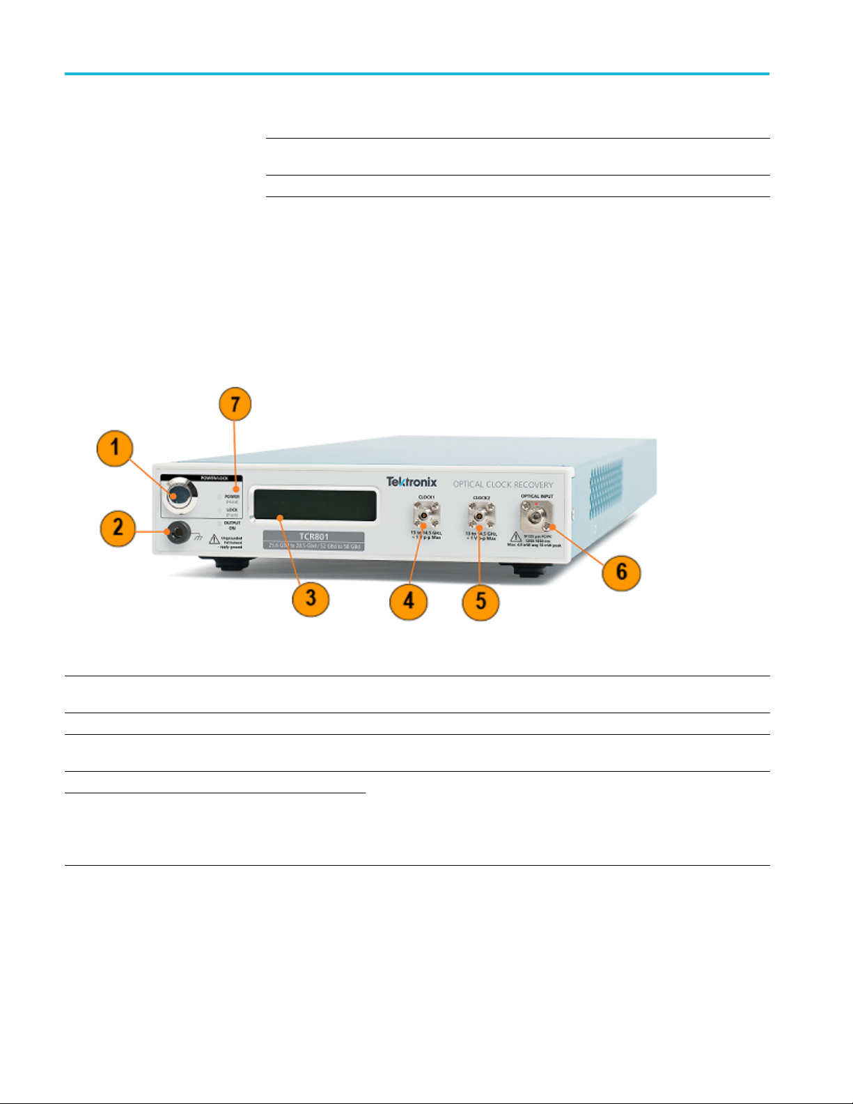
Item Connector Description
1 Power button
2 Antistatic connection A banana-jack short to ground
3
4
5
LCD display 61 mm (W) x 12 mm (H), 2 x 20 liquid crystal display (LCD). Used to display
CLOCK1
CLOCK2
Power button to power unit on/off . Once unit is on, push (and release) to
attempt a relock, or hold >5 sec) to switch unit to standby.
Ethernet Address and system state information
Clock electrical output (CLK/4 (13 GHz to 14.5 GHz) for a 52 to 58 Gbaud
input, CLK/2 (13 GHz to 14.5 GHz) for a 26 to 29 GBaud signal)
Single-ended, AC coupled, amplitude; Between 900 mVpp to 1.1 Vpp into
50 Ω terminated to ground. When output disabled, Vout RMS <5 mV
Both outputs are disabled/enabled at the same time.
8 TCR801 Installation and Safety Instructions

Item Connector Description
6
7
OPTICAL INPUT
Status LEDs Three LED's on the front panel to display Power (Hold), Lock (Push), and
1250-1650 nm s
electrical conversion for high dynamic range. FC/PC
Output On status.
Green = Locke
Orange = Unlocked
Orange Blinking = attempting to lock
Output on: L
outputs are enabled. LED is turned off when output disabled.
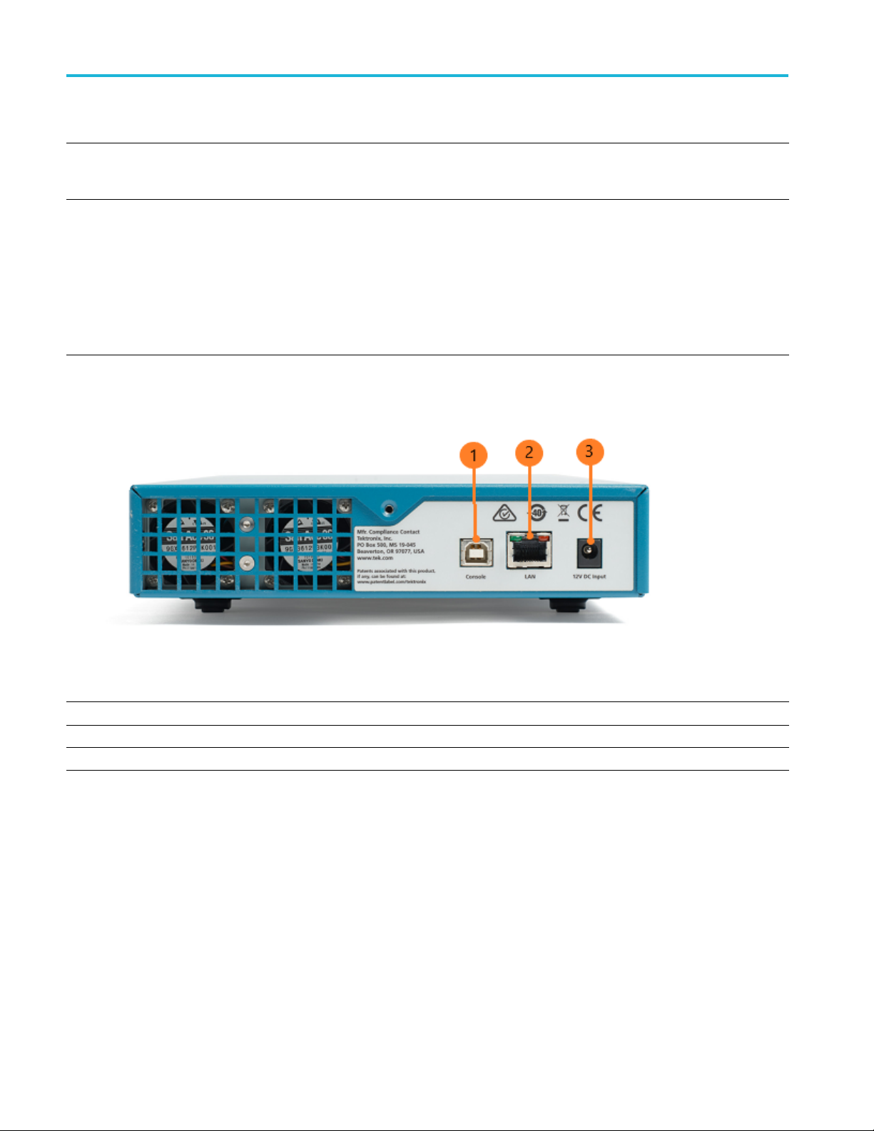
Rear panel
Introduction to the TCR801
ingle mode optical input with variable gain optical to
d
ight indicator should be green when either Clock1 or Clock2
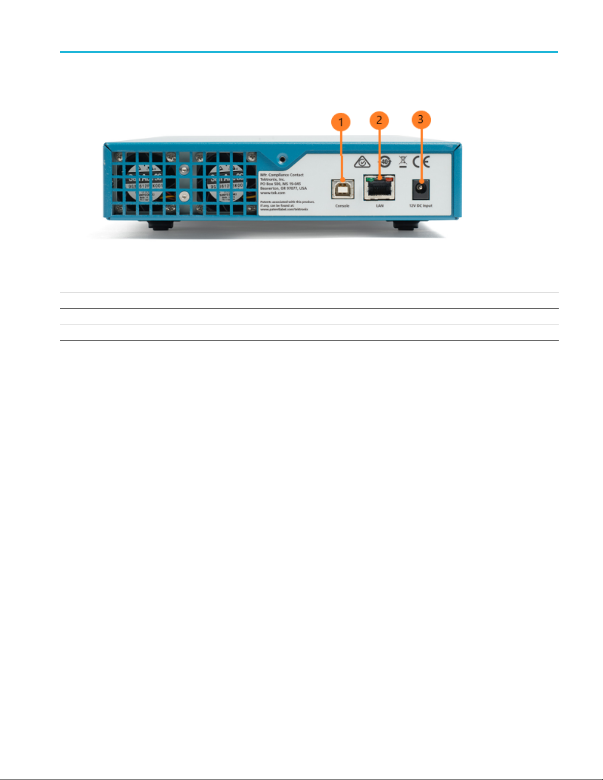
Item Connector Description
1
2LAN
3
USB USB Type B. Can be used to set static IP address
Base-T Ethernet (10/100/1000)
12V DC input Line 90-264 VAC power input
TCR801 Installation and Safety Instructions 9

Installation
Installation
Requirements
The TCR801 hardware can be installed as follows under the listed performance
conditions and power specifications. Ensure the performance conditions listed
here can be me
The Tektronix Optical Clock Recovery (OCR) software application you use to
control the instrument should be installed onto a Microsoft Windows OS PC. You
can also control the instrument without the application by using PI commands.
The following requirements must be met to install the OCR application and to
connect and use the instrument.
t before installing and powering on the instrument.
PC requirements for
Microsoft Windows 7 and above OS
OCR software application
installation
Power specifications
12 V DC input
Line 90-264 VAC power input
Key environmental and
physical specifications
Characteristic Specification
Temperature
Operating 0°C to +40°C, with 15°C/hour maximum gradient, non-condensing, derated 1.0 °C per 300
meters above 1,500 meters altitude.
Non-operating
Humidity
Operating 5% to 95% relative humidity ( RH) at up to +30°C,
Non-operating
Altitude
Operating Up to 3,000 meters, derate maximum operating temperature by 1°C per 300 meters above
Non-operating Up to 12,000 meters
-20°C to +60°C, with 30°C/hour maximum gradient
5% to 45% RH above +30°C up to +45°C, non-condensing, and as limited by a Maximum
Wet-Bulb Temperature of + 29°C (derates relative humidity to 32% RH at +45°C)
5% to 95% RH at up to +30°C,
5% to 45% RH above +30°C up to +60°C, non-condensing, and as limited by a Maximum
Wet-Bulb Temperature of + 29°C (derates relative humidity to 20% RH at +60°C)
1,500 meters altitude.
10 TCR801 Installation and Safety Instructions

Characteristic Specification
Weight
Height
Width
Depth
Clearance Rear: 5.08 cm (2 in)
4.5 kg (10 lbs), instrument only
56 mm (2.20 in), including feet
206 mm (8.11 i n)
561 mm (22.08 in)
Sides: 5.08 cm (2 in)
Bottom: Co
feet providing sufficient clearance.
oling inlets on the bottom require that the instrument rests on a flat surface with the
Installation
Performance conditions
Install OCR application
This instrument must have been calibrated at an ambient temperature between
+20° C and +30° C.
The instrument must have had a warm-up period of at least 10 minutes.
The instrument must be in an environment with temperature, altitude, and
humidity within the operating limits.
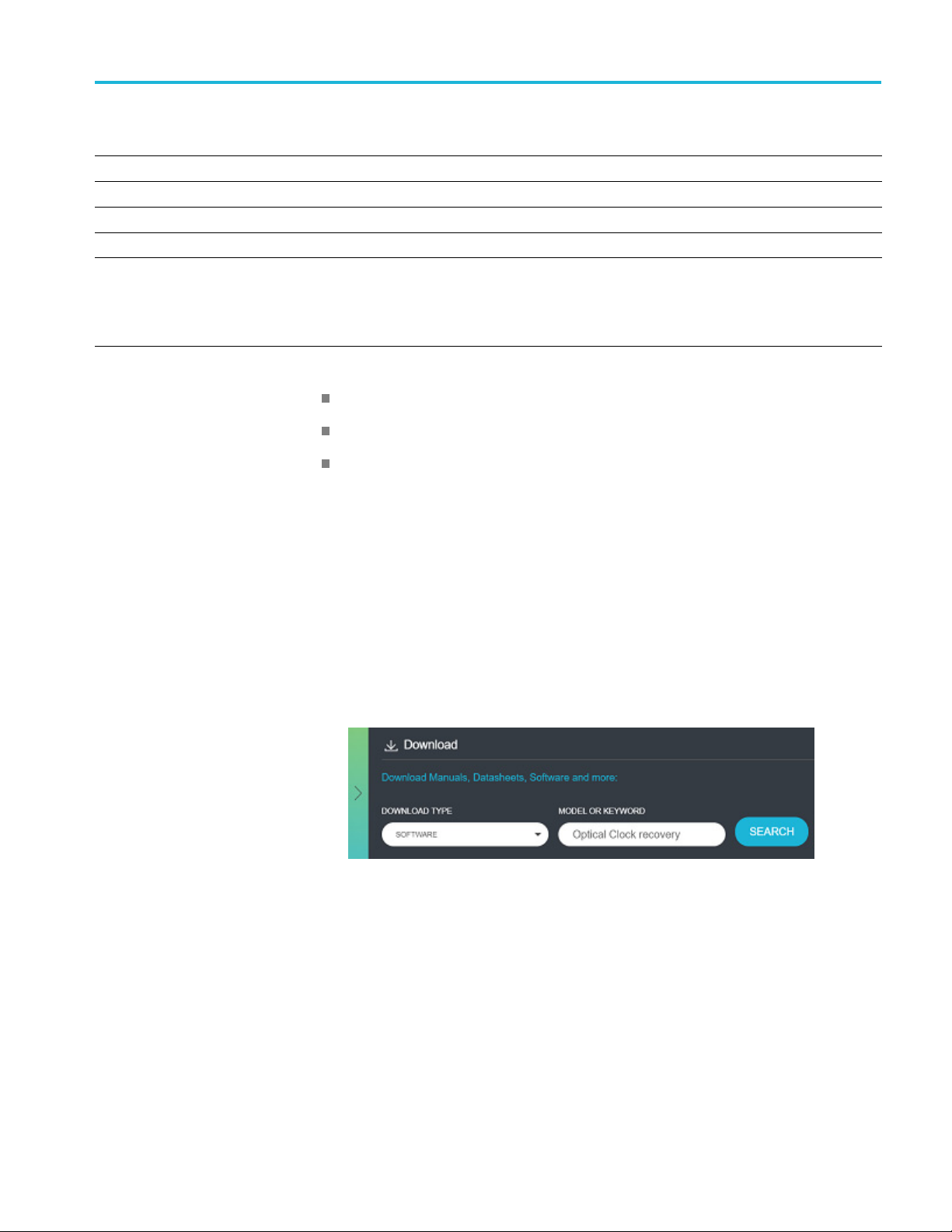
Complete the following steps to download and install the latest OCR application
software. You must have a Microsoft Windows 7 or above OS on the computer
onto which you want to install the software.
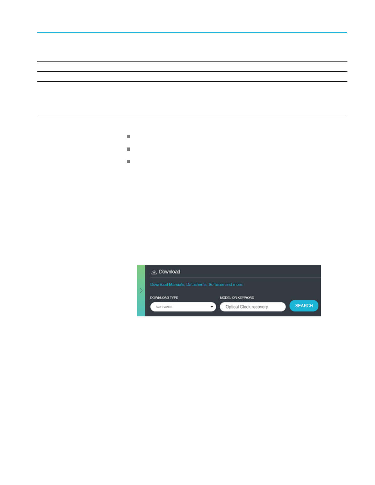
1. Go to www.tek.com.
2. Click Downloads. In the Download menu, select Software as the
DOWNLOAD TYPE, enter Optical Clock Recovery in the MODEL OR
KEYWORD field, and click SEARCH.
3. Select the latest version of software and follow the instructions to download
the application.
4. Double-click the executable and follow the on-screen instructions to install
the application.
TCR801 Installation and Safety Instructions 11

Installation
Connect and po
wer on instrument
How you connect the instrument to other devices depends on your use case and
desired setup. Regardless of your setup, the following steps apply. An connection
diagram is pr
setup.
1. Connect an E
TCR801.
2. Connect su
to the power source.
3. Press the
4. Launch the OCR application that is installed on the PC.
5. Select Utility > IP Configuration.
ovided at the end of this procedure as an example of one possible
Power button on the front panel to turn on the instrument.
thernet cable to the LAN connector on the rear panel of the
pplied 12 V power adapter to the rear panel of the TCR801 and
6. Select Silicon Labs COM as the port. Set the IP configuration as needed for
your computer and network through USB or Ethernet.
If the TCR01 is already connected, select the Socket radial button and enter
the IP address in Current IP. If not, proceed to the next step.
12 TCR801 Installation and Safety Instructions

7. Select File > Connect.
Installation
TCR801 Installation and Safety Instructions 13

Installation
8. The Connect pop
to which you want to connect and click Connect. The IP address will show
on the front panel display.
-up window will appear. Enter the IP address of the TCR801
14 TCR801 Installation and Safety Instructions

Installation
9. Click Update to
The instrument is now ready to use. Following is an example connection diagram
of the TCR801 a
complete the configuration.
nd TSO820 sampling oscilloscope using optical splitters.
TCR801 Installation and Safety Instructions 15

安全性に関する重要な情報
このマニュアルには、操作を行うユーザの安全を確保し、製品を安全
な状態に保つために順守しなければならない情報および警告が記載
されています。
このセクションの最後には、製品を安全に保守するために必要な追加情
報が記載されています (See page 3,
安全に保守点検していただくために
.)
安全にご使用いただく
製品は指定された方法でのみご使用ください。人体への損傷を避け、本
製品や本製品に接続されている製品の破損を防止するために、安全性に
関する次の注意事
くお読みください。必要なときに参照できるように、説明書を安全な場
所に保管しておいてください。
本製品は該当する地域の条例や国内法令に従って使用しなければな
りません。
本製品を正しく安全にご使用になるには、このマニュアルに記載された
注意事項に従うだけでなく、一般に認められている安全対策を徹底し
ておく必要があります。
本製品は訓練を受けた専門知識のあるユーザによる使用を想定してい
ます。
製品のカバーを取り外して修理や保守、または調整を実施できるの
は、あらゆる危険性を認識した専門的知識のある適格者のみに限定す
る必要があります。
使用前に、既知の情報源と十分に照らし合わせて、製品が正しく動作
していることを常にチェックしてください。
本製品は危険電圧の検出用にはご利用になれません。
ために
項をよくお読みください。すべての指示事項を注意深
危険な通電導体が露出している部分では、感電やアーク・フラッシュに
よってけがをするおそれがありますので、保護具を使用してください。
本製品をご使用の際に、より大きな他のシステムにアクセスしなければ
ならない場合があります。他のシステムの操作に関する警告や注意事項
については、その製品コンポーネントのマニュアルにある安全に関する
セクションをお読みください。
本機器をシステムの一部としてご使用になる場合には、そのシステムの
構築者が安全性に関する責任を果たさなければなりません。
TCR801型のインストールおよび安全に関する取扱説明書 1

安全性に関する重要な情報
火災や人体への損傷を
避けるには
適切な電源コードを使用して
る国で認定された電源コードのみを使用してください。
他の製品の電源コードは使
本製品を接地してください. 本製品は、メインフレームの電源コードの
グランド線を使用して間接的に接地します。感電を避けるため、グラン
ド線をアースに接続する必要があります。本製品の入出力端子に接続す
る前に、本製品が正し
電源コードのグランド接続を無効にしないでください。
電源を切断してください. 電源コードの取り外しによって主電源が遮断
されます。スイッチの位置については、使用説明書を参照してくださ
い。電源コードの取り扱いが困難な場所には設置しないでください。必
要に応じてすぐに電源を遮断できるように、ユーザが常にアクセスでき
る状態にしておく必要があります。
適切なACアダプタを使用してください. 本製品専用のACアダプタ
のみをご使用ください。
すべての端子の定格に従ってください. 火災や感電の危険を避けるた
めに、本製品のすべての定格とマーキングに従ってください。本製品
に電源を
してください。
接続する前に、定格の詳細について、製品マニュアルを参照
く接地されていることを確認してください。
ください. 本製品用に指定され、使用され
用しないでください。
コモン
本製品の測定端子は、AC 電源、カテゴリ II、 III、および IV 回路に
は使
カバーを外した状態では使用しないでください. カバーやパネルを外
した状態やケースを開いたまま動作させないでください。危険性の高
い電圧に接触してしまう可能性があります。
露出した回路への接触は避けてください. 電源が投入されているとき
に、露出した接続部分やコンポーネントに触れないでください。
故障の疑いがあるときは使用しないでください. 本製品に故障の疑いが
ある場合には、資格のあるサービス担当者に検査を依頼してください。
製品が故障している場合には、使用を停止してください。製品が故障し
ている場合や正常に動作していない場合には、製品を使用しないでくだ
さい。安全上の問題が疑われる場合には、電源を切って電源コードを取
り外してください。誤って使用されることがないように、問題のある製
品を区別しておいてください。
使用する前に、製品の外観に変化がないかよく注意してください。ひび
割れや欠落した部品がないことを確認してください。
端子を含む全ての端子には電位を印加しないでください。
用できません。
2 TCR801型のインストールおよび安全に関する取扱説明書

安全性に関する重要な情報
湿気の多いところでは動作さ
かい場所に移動する際には、結露にご注意ください。
爆発性のガスがある場所では使用しないでください.
製品の表面を清潔で乾燥した状態に保ってください. 製品の清掃を開始
する前に、入力信号を取り外してください。
適切に通気してください. 適切な通気が得られるように製品を設置でき
るように、マニュアルの設置手順を参照してください。
製品には通気用のスロットや開口部があります。その部分を覆ったり、
通気が妨げられたりすることがないようにしてください。開口部に
は異物を入れないでください。
安全な作業環境を確保してください. 製品は常にディスプレイやインジ
ケータがよく見える場所に設置してください。
キーボードやポインタ、ボタン・パッドを不適切に使用したり、長く押
しすぎたりしないでください。キーボードやポインタの使用を誤ると、
大けがにつながる可能性があります。
作業場が該当する人間工学規格を満たしていることを確認してくださ
い。ストレスに由来するけががないように、人間工学の専門家に助言
を求めてください。
せないでください. 機器を寒い場所から暖
本製品には指定された当社のラック取り付け金具のみを使用してくだ
さい。
安全に保守点検していただくために
「安全に保守点検していただくために」
点検を安全に行うために必要な詳細な情報が記載されています。資格の
あるサービス担当者以外は、保守点検手順を実行しないでください。保
守点検を行う前には、この
「安全にご使用いただくために」
感電を避けてください. 露出した接続部には触れないでください。
保守点検は単独で行わないでください. 応急処置と救急蘇生ができる人
の介在がない限り、本製品の内部点検や調整を行わないでください。
電源を切断してください. 感電を避けるため、保守点検の際には、製品
の電源を切り、電源コードを電源コンセントから抜いてから、カバーや
パネルを外したり、ケースを開いてください。
電源オン時の保守点検には十分注意し
な電圧や電流が存在している可能性があります。電源の切断、バッテ
リの取り外し(可能な場合)、テスト・リードの切断を行ってから、
のセクションには、製品の保守
「安全に保守点検していただくために」
を読んでください。
てください. 本製品には、危険
と
TCR801型のインストールおよび安全に関する取扱説明書 3

安全性に関する重要な情報
保護パネルの取り外し、はん
ください。
修理後の安全確認. 修理を行った後には、常にグランド導通と電源の絶
縁耐力を再チェックしてください。
本マニュアル内の用語
このマニュアルでは次の用語を使用します。
WARNING.
人体や生命に危害をおよぼすおそれのある状態や行為を
示します。
CAUTION.
本製品やその他の接続機器に損害を与えるおそれのある状態
や行為を示します。
本製品に使用される記号と用語
本製品では、次の用語を使用します。
だ付け、コンポーネントの交換を行って
危険:ただちに人体や生命に危険をおよぼす可能性があること
を示します。
警告:人体や生命に危険をおよぼす可能性があることを示します。
注意:
を示します。
本製
本製品を含む周辺機器に損傷を与える可能性があること
製品にこの記号が表記されているときは、マニュアルを参照し
て、想定される危険性とそれらを回避するために必要な行動に
ついて確認してください(マニュアルでは、この記号はユーザ
に定格を示すために使用される場合があります。)
品では、次の記号を使用します。
4 TCR801型のインストールおよび安全に関する取扱説明書

適合性に関する情報
このセクションでは、本製品が適合しているEMC基準、安全基準、お
よび環境基準について説明します。この製品は専門家および訓練を受
けた人のみが使用することを目的としています。家庭での使用や子供
による使用に対応して設計されていません。
以下の適合性に関するご質問は、以下の住所宛に、直接お問い合わせい
ただくこともできます:
Tektronix, Inc.
PO Box 500, MS 19‐045
Beaverton, OR 97077, USA
www.tek.com
EMC適合性
適合性に関する情報
欧州EMC指令
指令2014/30/EU電磁環境両立性に適合します。『Official Journal of the
European Communities』に記載の以下の基準に準拠します。
EN 61326-1:. 測定、制御、および実験用途の電子機器を対象とする
EMC基準。
CISPR 11: グループ1、クラスA、放射および伝導エミッション
IEC 61000-4-2: 静電気放電イミュニティ
IEC 61000-4-3: RF電磁界イミュニティ
IEC 61000-4-4: 電流高速トランゼント/バースト・イミュニティ
IEC 61000-4-5 電力線サージ・イミュニティ
IEC 61000-4-6 伝導RFイミュニティ
IEC 61000-4-8: 電力周波数磁界イミュニティ・テスト
IEC 61000-4-11: 電圧低下と瞬時停電イミュニティ
EN 61000-3-2. AC 電源ライン高調波エミッション
EN 61000-3-3. 電圧の変化、変動、およびフリッカ
123
EMC適合性
TCR801型のインストールおよび安全に関する取扱説明書 5
仕様表の記載製品と共に使用した場合は、指令2014/30/EU電磁環境両立
性に適合します。記載製品の公開EMC仕様を参照してください。その
他の製品と共に使用した場合、指令に適合しない可能性があります。
1
本製品は住居区域以外での使用を目的としたものです。住居区域で使用すると、電磁干
渉の原因となることがあります。

適合性に関する情報
オーストラリア/
ニュージーランド -EMC
2
本製品をテスト対象に接続し
ションが発生する可能性があります。
3
ここに挙げた各種EMC規
シェルを低インピーダンスで接続できるように、高品質なシールドを持つインタフェー
ス・ケーブルが必要です。
た状態では、この規格が要求するレベルを超えるエミッ
格に確実に準拠するには、ケーブル・シールドとコネクタ・
ACMAに従い、次の規格に準拠することでRadiocommunications Actの
EMC条項に適合しています。
EN 61326-1:グループ1、クラスA、放射および伝導エミッション
6 TCR801型のインストールおよび安全に関する取扱説明書

環境条件
適合性に関する情報
このセクションでは、本製品が環境におよぼす影響について説明し
ます。
有害物質に関する規制
使用済み製品の処理方
法
RoHS2指令2011
機器またはコンポーネ
ンを順守してください。
機器のリサイクル. 本製品の製造には天然資源が使用されています。こ
の製品には、環境または人体に有害となる可能性のある物質が含まれて
いるため、製品を廃棄する際には適切に処理する必要があります。有害
物質の放出を防ぎ
利用とリサイクルの徹底にご協力ください。
バッテリのリサイクル. 本製品には小型のリチウム・メタル・ボタン電
池が内蔵されています。使用済み電池の廃棄については、お住まいの地
域の所轄官
過塩素酸塩の取り扱い. 本製品にはCRリチウム電池が搭載されていま
す。CRリチウム電池はカリフォルニア州法により過塩素酸塩材とし
て規定され、特別な取り扱いが求められています。詳細については、
www.dtsc.ca.gov/hazardouswaste/perchlorateを参照してください。
/65/EUに適合。
ントをリサイクルする際には、次のガイドライ
、天然資源の使用を減らすため、本製品の部材の再
このマークは、本製品がWEEE(廃棄電気・電子機器)および
バッテリに関す
の諸要件に準拠していることを示しています。リサイクル方
法については、当社の Web サイトのサービス・セクション
(www.te
庁にお尋ねください。
k.com/productrecycling)を参照してください。
る指令2012/19/ECおよび2006/66/ECに基づき、EU
TCR801型のインストールおよび安全に関する取扱説明書 7

TCR801型の概要
TCR801型の概要
TCR801型光クロック・リカバリは、26GBdと53GBdに対応した、デュア
ル・バンド・クロック・リカバリ・ユニットです。TCR801型は高度な
アーキテクチャを備えており、規格に準拠するように位相ロック・ルー
プ(PLL)帯域を調整することができます。また、他のテスト/測定機
器と組み合わせて使用
不可欠なコンポーネントとして活用していただけます。
することもできるので、光設計のテストや検証に
主な特長
以下の2つのレンジに対応:
25.6~29GBd(PAM2/NRZ/PAM4)
51.2~58GBd(PA M2 、NRZ、PAM 4 )
波長:1,250nm~1,650nm
標準的なコンプライアンス・テストに必要な"最適なPLL"応答を構
成するための調整可能なPLL帯域
Ethernet(IEEE標準インタフェース):スタンドアロンPCソフト
ウェアまたはVISA/Tek-VISAを使用して、PIを介してネットワーク
経由での遠隔操作が可能
2つの独立したRFクロック出力
前面パネルからインテリジェントなオート・リロック機能とマニュ
アル・リロック機能を利用可能
液晶ディスプレイ(2×20):ネットワークIPアドレス、現在のロッ
ク状態、測定されたシンボル・レートなどを表示
デバイス制御用イーサネット・ポート
IP構成のリセット用USB Type Bポート
外部12V電源
スタンダード・アクセサリ
本機には以下のスタンダード・アクセサリが同梱されています。オプ
ショナル・アクセサリやその他のオプションに関する詳細は、TCR801
型のデータ・シート(www.tek.com)をご覧ください。
概要 数量 当社部品番号
Ethernetケーブル、2m(CAT6
GIGE)、ダブル・シールド
50%/50%シングル・モード
FC-PCスプリッタ
8 TCR801型のインストールおよび安全に関する取扱説明書
1 174-7292-00
1 167-4333-00
製品マニュアル
前面パネル
TCR801型の概要
概要 数量 当社部品番号
50Ω同軸SMA ターミネータ
12VDC 5 A AC-DC電源、50~
60Hz、100~250
テスト・リード、バナナ-バ
ナナ、約460mm
VAC
2 015-1022-01
1 119-8726-00
1 174-7295-00
以下の製品マニュアルは、当社Web サイト(www.tek.com)からダウ
ンロードできます。
アイテム コネクタ 説明
1
2
3
4
5
電源ボタン
帯電防止コネクタ
LCDディスプレイ
CLOCK1
CLOCK2
電源ボタンを押して、電源をオン/オフにします。オンの
状態で押して離すと、再ロックします。または5秒以上押し
たままにすると、スタンバイに切り替わります。
バナナジャックでグランドにショートします。
61mm×12mm(幅×高さ)、2行×20文字のLCD(Liquid Crystal
Display)。Ethernetアドレスやシステム
るために使用します。
クロック電気出力(52~58Gbaud入力の場合:CLK/4(13GHz~
14.5GHz)、26~29GBaud 信号の場合
14.5GHz))。
シングルエンド、AC結合、振幅:900mVpp~1.1 Vpp、50Ωで
グランドに終端。出力無効時のVout RMSは5m
両方の出力は同時に無効化/有効化されます。
状態の情報を表示す
:CLK/2 (13GHz~
V未満。
TCR801型のインストールおよび安全に関する取扱説明書 9
TCR801型の概要
アイテム コネクタ 説明
6
7
光入力
ステータスLED
可変利得制御を使用した1,250~1,650nmのシングル・モー
ド光入力。高ダイナミック・レンジのO/E変換に利用可
能。FC/PCコネクタ。
前面パネルの3つのLED
(プッシュ)、出力オンの状態を表示します。
出力がオンのときに、Clock1またはClock2の出力が有効に
なっている場合は、ラ
効時はLEDが消灯します。
後部パネル
で、電源(ホールド)、ロック
緑 = ロック状態
オレンジ = ロック解除
オレンジ(点滅) = ロック試行中
ンプが緑色に点灯します。出力無
アイテム コネクタ 説明
1
2 LAN
3
USB
12V DC入力 電源入力(90~264 VAC)
USB Type B。スタティックIPアドレスの設定に使用可能
10/100/1000 BASE-T Ethernet
10 TCR801型のインストールおよび安全に関する取扱説明書

設置
設置
要件
OCRソフトウェア・ア
プリケーションのイン
ストールに必要なPC環
境
電源仕様
TCR801型のハードウ
源仕様に従ってください。本機を設置して電源を入れる前に、ここに記
載されている性能条件が満たされていることを確認してください。
本機の制御に使用するテクトロニクスのOCR(Optical Clock Recovery)
ソフトウェア・アプリケーションが、PC(Microsoft Windows OS)上に
インストールされている必要があります。また、PIコマンドを使用する
ことで、アプリケーションを介さずに本機を制御することもできます。
OCRアプリケーションをインストールし、本機を接続して使用するに
は、以下の要件を満たす必要があります。
Microsoft Windows 7以上のOS
12V DC入力
ェアを設置する際は、以下のような性能条件と電
電源入力(90~264 VAC)
主な環境/物理仕様
特性 仕様
温度
動作時
非動作時
湿度
動作時
非動作時
高度
動作時 最高3,000m(高度が1,500m を超えると300mごとに最大動作温度が1℃低下)
0℃~+40℃、最大15℃/hの傾き、結露のないこと。高度が1,500m を超える
と300mごとに最大動作温度は1℃低下
-20℃~+60℃(最大30℃/hの傾き)
+30℃以下で相対湿度5%~95%(RH)、
結露のないこと。+30℃より上、+45℃以下で5%~45%の相対湿度(RH)。
最高湿球温度+29℃(+45℃で相対湿度は32%に低下)
+30℃以下で相対湿度5%~95%、
結露のないこと。+30℃より上、+60℃以下で5%~45%の相対湿度(RH)。
最高湿球温度+29℃(+60℃で相対湿度は20%に低下)
TCR801型のインストールおよび安全に関する取扱説明書 11

設置
特性 仕様
非動作時
質量 4.5kg(10lbs、機器のみ)
高さ
幅
奥行
スペース
最高12,000m
56mm(2.20イン
206mm(8.11インチ)
561mm(22.0
後部:5.08cm(
側面:5.08cm(2インチ)
底部:底部の冷却インレットでは、機器が平らな面に設置されており、足
元に十分な隙間がな
チ)、脚を含む
8インチ)
2インチ)
ければなりません。
性能条件
周囲温度+2
0°C~+30°C の範囲に適応するように、機器が校正
されていること。
機器は、最低10分間ウォーム・アップされていること。
動作限界値の範囲内の温度、高度、湿度のある環境に、機器が設置
されていること。
OCRアプリケーションのインストール
最新のOCRアプリケーション・ソフトウェアをダウンロードしてイン
ストールするには、次の手順を実行します。ソフトウェアをインス
トールするコンピュータにMicrosoft Windows 7以降のOSを搭載してい
る必要があります。
1. 当社We b サイト(www.tek.com)を訪問します。
2. Downloads(ダウンロード)をクリックします。Download(ダウン
ロード)メニューで、ダウンロード・タイプとしてSoftware(ソフ
トウェア)を選択し、型名またはキーワードのフィールドにOptical
Clock Recovery(光クロック・リカバリ)と入力して、SEARCH
(検索)をクリックします。
3. ソフトウェアの最新バージョンを選択して、指示に従ってアプリ
ケーションをダウンロードします。
4. 実行ファイルをダブルクリックし、画面の指示に従ってアプリケー
ションをインストールします。
12 TCR801型のインストールおよび安全に関する取扱説明書

機器の接続と起動
設置
本機を他の機器にどのように接続するかは、活用事例や設定によって異
なります。セットアップの種類に関わらず、以下の手順が適用されま
す。この手順の最後に、セットアップの一例として接続図を示します。
1. EthernetケーブルをTRC801型の後部パネルのLANコネクタに接続し
ます。
2. 付属の12V電源アダプタをTCR801型の後部パネルと電源に接続し
ます。
3. 前面パネルの電源ボタンを押して、電源をオンにします。
4. PCにインストールされているOCRアプリケーションを起動します。
5. Utility(ユーティリティ) > IP Configuration(IP接続)を選択し
ます。
6. ポートとして"Silicon Labs COM"を選択します。USBまたはEthernet
を介して`,コンピュータやネットワークに必要に応じてIP構成を
定します。
設
TCR01型がすでに接続されている場合は、Socket(ソケット)ラジ
オ・ボタンを選択し、Current IP(現在のIP)にIPアドレスを入力し
ます。接続されていない場合は、次のステップに進みます。
TCR801型のインストールおよび安全に関する取扱説明書 13

設置
7. File(ファイル)> Connect(接続)を選択します。
14 TCR801型のインストールおよび安全に関する取扱説明書

設置
8. Connect(接続)ポッ
のTCR801型のIPアドレスを入力して、Connect(接続)をクリック
します。前面パネルのディスプレイにIPアドレスが表示されます。
プアップ・ウィンドウが表示されます。接続先
TCR801型のインストールおよび安全に関する取扱説明書 15

設置
9. Update(更新)をクリ
これで本機を使用する準備が整いました。以下に、TCR801型と光ス
プリッタを使用したTSO
例を示します。
ックして構成を完了します。
820型サンプリング・オシロスコープの接続
16 TCR801型のインストールおよび安全に関する取扱説明書

중요한 안전 정보
이 매뉴얼에는 제품을 안전하게 작동하고 안전한 상태로 유지하기 위해 사
용자가 준수해야 하는 정보와 경고가 수록되어 있습니다.
이 제품에 대한 서비스를 안전하게 수행할 수 있도록 이 섹션의 끝부분에는
추가정보가나와있습니다.(Seepage3,
일반 안전 사항 요약
서비스 안전 사항 요약
.)
제품은 지정된 대로만 사용합니다. 다음
또는 관련 제품의 손상이나 사용자 부상을 방지합니다. 모든 지침을 주의
깊게 읽어보고 나중에 참조할 수 있도록 이 지침을 보관해 두십시오.
본 제품은 지역 및 국가 코드에 따라 사용해야 합니다.
제품을 올바르고 안전하게 작동하려면 본 설명서에 명시된 안전 예방책뿐
만 아니라 일반적으로 승인된 안전 절차를 반드시 준수해야 합니다.
이 제품은 숙련된 전문가만 사용해야 합니다.
관련 위험에 대해 제대로 알고 있는 숙련된 전문가만 수리, 유지 관리 또는
조정을 위해 덮개를 제거해야 합니다.
사용하기 전에 항상 알려진 소스를 통해 제품이 정상 작동하고 있는
지 확인합니다.
이 제품은 위험한 전압을 감지하기 위한 용도로 사용되지 않습니다.
개인 보호 장비를 착용하여 위험한 도체가 노출돼 있는 장소에서의 감전 및
아크 폭발로 인한 부상을 방지합니다.
이제품을사용하는동안더큰시스템의다른부품에접근해야할수도있
습니다. 시스템작동과관련된경고및주의사항에대해서는기타구성요
소매뉴얼의안전사항섹션을읽어보십시오.
이 장비를 시스템에 통합할 때는 시스템 조립업체에서 해당 시스템의
안전을 확인해야 합니다.
안전 예방책을 검토하여 이 제품
화재 또는 부상을 방지
하려면
TCR801 설치 및 안전 지침 1
적절한전원코드사용. 이 제품에 지정되어 있고, 제품을사용중인국가
에서 승인된 전원 코드만 사용합니다.
제공된 전원 코드를 다른 제품에 사용하지 마십시오.
제품 접지. 본제품은메인프레임전원코드의접지도체를통해간접적으
로 접지됩니다. 감전을방지하려면접지도체를접지에연결해야합니
다. 제품의 입력 또는 출력 단자에 연결하기 전에 제품이 적절히 접지되
었는지 확인합니다.
전원 코드 접지 연결을 비활성화하지 않습니다.

중요한 안전 정보
전원 분리. 전원 코드를 뽑아 제
치는 지침을 참조하십시오. 전원코드를작동하기어렵도록장비를배
치하지 마십시오. 전원 코드는 필요한 경우 신속하게 분리할 수 있도록
항상 사용자가 쉽게 접근할 수 있어야 합니다.
적절한 AC 어댑터 사용. 이 제품에 사용하도록 지정된 AC 어댑터만 사용
합니다.
모든 단자 정격 준수. 화재나감전위험을방지하기위해제품의모든정
격과 표시를 준수합니다. 제품에연결하기전에제품설명서를참조하
여 추가 정격 정보를 확인합니다.
공통 단자를 비롯하여 단자에 최대 정격을 적용하지 마십시오.
본 제품의 측정 단자는 메인 또는 범주 II, III, IV 회로에 연결하도록 정격
이 지정되지 않았습니다.
덮개 없이 작동 금지. 덮개 또는 패널을 제거하거나 케이스를 연 상태로 이
제품을 작동하지 마십시오. 위험 수준의 전압에 노출될 수 있습니다.
회로 노출 방지. 전원이공급중일때는노출된연결부와구성요소를만
지지 마십시오.
고장이 의심되는 제품 작동 금지. 본 제품이 손상된 것 같으면 전문 서비스
직원의 검사를 받습니다.
품과 전원을 분리합니다. 전원 스위치의 위
제품이 손상되었을 경우 비
동하지 않을 경우 사용하지 않습니다. 제품 안전과 관련하여 의심되는 내
용이 있을 경우 제품의 전원을 끄고 전원 코드를 분리합니다. 더이상제품
을 작동하지 않도록 제품에 안전 관련 내용을 명확하게 표시합니다.
제품을사용하기전에제품외부를검사합니다. 깨지거나 누락된 부품이
있는지 확인합니다.
축축하고 습기가 많은 환경에서 작동 금지. 장치를 서늘한 환경에서 따뜻
한 환경으로 옮기면 응축 현상이 나타날 수 있습니다.
폭발 위험이 있는 장소에서 작동 금지.
제품 표면을 깨끗하고 건조하게 유지하십시오. 제품을 청소하기 전에
입력 신호를 제거합니다.
적절하게 환기시키십시오. 적절히 환기되도록 제품을 설치하는 방법에
대한 자세한 내용은 설명서의 설치 지침을 참조하십시오.
환기를위해제공되는슬롯과환기구가덮이거나가려지지않도록하고,
환기구에 물체를 넣지 마십시오.
안전한작업환경제공. 항상 화면 및 표시기를 보기 편한 위치에 제품
을 배치합니다.
활성화합니다. 제품이 손상되었거나 제대로 작
2 TCR801 설치 및 안전 지침

중요한안전정보
키보드, 포인터및버튼패드를
않습니다. 키보드나 포인터를 부적절하게 사용하거나 장기간 사용하면
심각한 부상을 입을 수 있습니다.
작업 구역이 해당하는 인체 공학 표준을 충족해야 합니다. 스트레스로 인
한 부상을 방지하려면 인체 공학 전문가에게 문의하십시오.
이 제품에 사용하도록 지정된 텍트로닉스 랙 마운트 하드웨어만 사용
합니다.
서비스안전사항요약
서비스 안전 사항 요약
데 필요한 추가 정보가 나와 있습니다. 전문가만이 서비스 절차를 실시해
야 합니다. 서비스 절차를 수행하기 전에 본
안전 사항 요약
감전을 방지하려면. 노출된 연결부를 만지지 마십시오.
단독으로 서비스 수행 금지. 응급처치및소생술을실시할수있는사람이
없는 경우 이 제품에 대한 내부 서비스나 조정 작업을 수행하지 마십시오.
전원 분리.
끄고 주 전원으로부터 전원 코드를 분리한 후에 덮개, 패널 또는 환기구
를 제거합니다.
부적절하게 사용하거나 장기간 사용하지
섹션에는 제품에 대해 안전하게 서비스를 실시하는
서비스 안전 사항 요약및일반
을 읽어보십시오.
감전을 방지하려면 서비스를 실시할 때 제품 전원 스위치를
설명서의 용어
본
전원을켠상태로서비스수행시주의. 이제품에는위험한전압이나전
류가 흐를 수 있습니다. 보호 패널을 제거하거나, 구성 요소를 솔더링
또는 교
후 테스트 리드선을 분리합니다.
수리후안전확인. 수리 후 항상 접지 연속성 및 주 전원의 절연 파괴
강도를 다시 확인합니다.
다음용어가본설명서에나타날수있습니다.
WAR NING .
을 명시합니다
CAUTION.
이나 상황을 명시합니다
체하기전에전원을분리하고배터리를제거(해당하는 경우)한
경고문은 부상이나 사망을 초래할 수 있는 조건이나 상황
.
주의문은본제품또는기타재산상의피해를줄수있는조건
.
TCR801 설치 및 안전 지침 3
컴플라이언스 정보
제품의 기호 및 용어
다음 용어가 제품에 나타날 수 있습니다.
위험은 표지를 인지한 후부터 언제든지 발생할 수 있는 부상 위험
을 나타냅니다.
경고는 표지를 읽는 동안 즉시 발생하지는 않는 부상 위험을 나타냅니다.
주의는 제품을 포함한 재산상의 위험을 나타냅니다.
제품에 이 기호가 표시되면 설명서를 참조하여 잠재적인 부상
위험의 특성과 해당 위험을 방지하기 위해 취해야 하는 조치를
확인하십시오. 설명서에 나오는 등급을 언급할 때에도 이 기호
가사용될수있습니다.
제품에는 다음과 같은 기호가 표시될 수 있습니다.
컴플라이언스 정보
이 섹션에서는 장비가 준수하는 EMC(전자파 컴플라이언스), 안전 및
표준이 나와 있습니다. 본제품은전문가와숙련된사용자만사용할수있
습니다. 가정에서 또는 어린이가 사용하도록 설계된 제품이 아닙니다.
다음 컴플라이언스 정보에 대한 질문은 아래의 주소로 보내 주시면 됩니다.
Tektronix, Inc.
PO Box 500, MS 19-045
Beaverton, OR 97077, USA
www.tek.com
EMC 컴플라이언스
EU EMC 지침
전자파 적합성에 대한 지침 2014/30/EU의취지에부합합니다. 유럽 공동체
의 공식 저널에 실려 있는 다음 사양을 준수하는 것으로 입증되었습니다.
EN 61326-1. 측정, 제어및실험실용전기장비에대한EMC 요구 사항
CISPR 11. 복사성 및 전도성 방출, 그룹 1, A등급
IEC 61000-4-2. 정전기방전차단
환경
123
IEC 61000-4-3. RF 전자기장 차단
IEC 61000-4-4. 전기 고속 과도 전류/버스트 차단
4 TCR801 설치 및 안전 지침

컴플라이언스 정보
EMC 컴플라이언스
IEC 61000-4-5.
전원 라인 서지 차단
IEC 61000-4-6. 전도된 RF 차단
IEC 61000-4-8. 전원 주파수 자기장 차단 테스트
IEC 61000-4-11. 전압 하락과 중단 차단
EN 61000-3-2. AC 파워라인 고조파 방출
EN 61000-3-3. 전압 변화, 변동 및 깜박임
사양 표에 명시된 제품을 사용하는 경우 전자파 적합성에 대한 지침
2014/30/EU의 목적을 준수합니다. 명시된 제품은 게시된 EMC 사양을
참조하십시오. 다른 제품을 사용하는 경우 지침의 목적을 준수하지 않
아도 됩니다.
1
본 제품은 비주거 지역에서만 사용하도록 만들어졌습니다. 주거 지역에서 사용하면 전자
기파 간섭이 발생할 수 있습니다.
2
이 장비를 테스트 대상에 연결하면 이 표준의 요구 레벨을 초과하는 방출이 발생할 수 있습니다.
3
위에 나열된 EMC 표준을 준수하려면 케이블 피복과 커넥터 쉘 간의낮은 임피던스 연결을 통
합하는, 고품질의 피복 인터페이스 케이블을 사용해야 합니다.
호주/뉴질랜드 EMC
ACMA에따라다음표준에대해EMC 무선 통신법 조항을 준수합니다.
EN 61326-1. 복사성 및 전도성 방출, 그룹 1, A등급
TCR801 설치 및 안전 지침 5
TCR801 소개
환경 고려 사항
이섹션에서는제품이환경에미치는영향에대한정보를제공합니다.
유해 물질 제한
제품 폐기 처리
RoHS2 지침 2011/65/EU를 준수합니다.
장비나 구성 요소를 재활용할 때 다음 지침을 준수하십시오.
장비 재활용. 본 장비를 생산하기 위해 천연자원을 추출하여 사용했습니다.
제품을 부적절하게 폐기하면 장비에 들어 있는 물질이 환경이나 인간의 건
강에 해를 끼칠 수 있습니다. 이러한물질이환경에침투하는것을막고천
연자원의 사용량을 줄이기 위해서는 대부분의 재료가 올바르게 재사용 또
는 재활용되도록 적절한 시스템에서 본 제품을 재활용하는 것이 좋습니다.
이기호는본제품이WEEE(폐전기전자 지침) 및배터리에대
해 Directive 2012/19/EU 및 2006/66/EC에의거하여적용가능한유럽
연합의 요구 사항을 준수함을 나타냅니다. 재활용 옵션에 대한
자세한 내용은 텍트로닉스 웹 사이트(www.tek.com/productrecycling)
를 확인하십시오.
배터리 재활용. 이 제품에는 소형 장착형 리튬 금속 버튼 셀이 포함되어
있습니다. 셀은 수명이 끝나면 현지 관할 규정에 따라 적절히 폐기하거
나 재활용하십시오.
과염소산염 자재. 이 제품에는 하나 이상의 CR 유형의 리튬 배터리
가 포함되어 있습니다. 캘리포니아주에서는 CR 리튬 배터리가 과
염소산염 자재로 분류되므로 특별 취급해야 합니다. 자세한 내용은
www.dtsc.ca.gov/hazardouswaste/perchlorate를 참조하십시오.
TCR801 소개
TCR801 광학 클럭 복구는 중심이 26~53GBd에있는듀얼밴드클럭복구장
비입니다.TCR801의 고급 아키텍처는 표준을 준수하도록 PLL(위상고정
루프) 대역폭을조정할수있도록하며, 다른 테스트 및 측정 장비와 함께 사
용할 경우 광학 디자인의 테스트 및 검증에서 중요한 구성 요소입니다.
키기능
6 TCR801 설치 및 안전 지침
다음두범위에서잠기도록설계되었습니다.
25.6~29GBd PAM2/NRZ 또는 PAM4
51.2~58GBd PAM2/NRZ 또는 PAM4
1250nm~1650nm 파장
표준 컴플라이언스 테스트에 필요한 “골든 PLL” 응답을 구성하도록
조정 가능한 PLL 대역폭

TCR801 소개
기본 액세서리
독립형 PC 소프트웨어를 사용
하여 네트워크를 통해 또는
VISA/Tek-VISA를사용하여PI를통해원격으로장비를실행하는IEEE
이더넷 제어 인터페이스
별도의 두 RF 클럭 출력을 제공합니다.
장비 전면 패널에서 사용
할 수 있는 지능형 자동 재잠금 기능 및 수
동 재잠금 기능
2x20LCD는측정
된 속도 전환을 포함하여 네트워크 IP 주소및현재
잠금 상태를 보는 데 사용됩니다.
장치제어를위한이더
넷포트
IP 구성 재설정을 위한 USB 유형 B 포트
외부 12V 전원 공급기
이 장비는 다음 표준 액세서리와 함께 제공됩니다. 옵션 액세서리 및 기
타 옵션 목록에 대해서는 www.tek.com에서 TCR801 데이터 시트를 참
조하십시오.
설명 수량 텍트로닉스 부품 번호
이더넷 케이블, 2m(CAT6 GIGE),
이중 피복
50%/50% 단일 모드 FC-PC 분할
기
50Ω 동축 SMA 터미네이터
DC 5A AC-DC 전원 공급기,
12V
50~60Hz, 100~250VAC
테스트
인치
리드선, 바나나 간,18
1 174-7292-00
1 167-4333-00
2 015-1022-01
1119
1 174
-8726-00
-7295-00
TCR801 설치 및 안전 지침 7

TCR801 소개
제품 설명서
전면 패널
다음 제품 설명서는 www.tek.com에서 다운로드할 수 있습니다.
품목 커넥터 설명
1
2
3
4
5
6
7
전원 버튼 전원 장치를 켜거나 끄기 위한 전원 버튼입니다. 장치가 켜져
있으면 눌렀다 떼어 재잠금을 시도하거나,5초이상눌러서장
치를 대기 상태
정전기방지연결 바나나잭접지에단락
LCD 디스플레이 61mm(W) x 12mm(H), 2 x 20 액정 표시 장치(LCD). 이더넷 주소 및
시스템 상태 정보를 표시하는 데 사용됨
CLOCK1
CLOCK2
광입력 1250~1650nm 단일 모드 광 입력(높은 동적 범위에 대해 변수 게
상태 LED 전면 패널에 전원(유지), 잠금(누름) 및출력켜기상태를표시
클럭 전기 출력(52~58Gbaud 입력의 경우 CLK/4(13GHz~14.5GHz),
26~29GBaud 신호의 경우 CLK/2(13GHz~14.5GHz))
싱글 엔드,
된 50Ω 사이. 출력이 비활성화되면 Vout RMS <5mV
두 출력이 동시에 비활성화/활성화됩니다.
인 광학에서 전자 방식으로 변환). FC/PC
하는 3개의 LED가있습니다.
출력
색입니다. 출력이 비활성화되면 LED가 꺼집니다.
로 전환합니다.
AC 커플됨, 진폭: 900mVpp~1.1Vpp에서 접지에 종단
잠긴 상태
녹색 =
주황색 = 잠금 해제된 상태
주황색으로 깜박임 = 잠금을 시도하는 중
켜기: 표시등은 Clock1 또는 Clock2 출력이 활성화되면 녹
8 TCR801 설치 및 안전 지침

후면 패널
품목 커넥터 설명
1
2LAN
3
USB
12V DC 입력 라인 90~264VAC 전원 입력
USB 유형 B. 정적 IP 주소를설정하는데사용할수있습니다.
Base-T 이더넷(10/100/1000)
TCR801 소개
TCR801 설치 및 안전 지침 9

설치
설치
요구 사항
OCR 소프트웨어 애플리
케이션 설치에 대한 PC
요구 사항
전원 사양
TCR801 하드웨어는 나
치할 수 있습니다. 장비를 설치하고 전원을 켜기 전에 여기에 나열된 성
능 상태가 충족되는지 확인합니다.
장비를 제어하는 데 사용하는 텍트로닉스 OCR(광학 클럭 복구) 소프트웨
어 애플리케이션을 Microsoft Windows OS PC에 설치해야 합니다. 또한 PI
명령을 사용하여 애플리케이션 없이 장비를 제어할 수도 있습니다.
OCR 애플리케이션을 설치하고 기기를 연결 및 사용하려면 다음 요구
사항을 충족해야 합니다.
Microsoft Windows 7 이상 OS
12V DC 입력
라인 90~264VAC 전원 입력
열된 성능 상태 및 전원 사양에 따라 다음과 같이 설
핵심 환경 및 물리적 사
양
특성 사양
온도
작동 최대 변화가 15°C/시일 경우 0°C~+40°C, 비응축, 1,500m 초과 고도에서 300m
당 1.0°C 감소
비작동 최대 변화가 30°C/시일 경우 -20°C~+60°C
습도
작동 최대 +30°C까지 5% ~95% RH(상대 습도)
+30°C 이상 최대 +45°C까지 5%~45% RH, 비응축식, 최대 습구 온도 +29°C에의
해 제한됨(+45°C에서 상대 습도를 32% RH로줄임)
비작동 최대 +30°C에서 5%~95% RH
+30°C 이상 최대 +60°C까지 5%~45% RH, 비응축식, 최대 습구 온도 +29°C에의
해 제한됨(+60°C에서 상대 습도를 20% RH로줄임)
고도
작동 최대 3,000m, 1,500m 고도 이상에서 300m당최대작동온도1°C 감소
비작동 최대 12,000m
10 TCR801 설치 및 안전 지침
특성 사양
무게 4.5kg(10lbs)
높이 다리 포함 56mm(2.20인치)
폭
깊이 561mm(22.08
공간 후면:5.08cm(2인치)
206mm(8.11인치)
측면:5.08cm(
하단: 하단의 냉각 흡입구를 사용하려면 장비가 평평한 표면에 놓여 있고 다리
부분에 충분한 공간이 있어야 합니다.
, 장비만
인치)
2인치)
설치
성능 조건
이 장비는 주변 온도가 +20°C에서 +30°C 사이일 때 교정해야 합니다.
장비는 최소 10분
장비는 온도, 고도 및 습도가 작동 한도 내인 환경에서 사용해야 합니다.
OCR 애플리케이션 설치
다음 단계를 완료하여 최신 OCR 애플리케이션 소프트웨어를 다운로드한
후 설치하십시
이상 OS가 있어야 합니다.
1. www.t
2. 다운로드를 클릭합니다. 다운로드 메뉴에서 다운로드 유형으로 소프
트웨어를
한후검색을 클릭합니다.
간 예열해야 합니다.
오. 소프트웨어를 설치하려는 컴퓨터에 Microsoft Windows 7
ek.com으로 이동합니다.
선택하고 모델 또는 키워드 필드에 광학 클럭 복구를입력
3. 최신 버전의 소프트웨어를 선택하고 지침에 따라 애플리케이션을 다
운로드합니다.
4. 실행파일을두번클릭하고화면의지침에따라애플리케이션을 설치
합니다.
TCR801 설치 및 안전 지침 11

설치
장비 연결 및 전원 켜기
장비를 다른 장치에 연결하는 방법은 사용 사례 및 원하는 설정에 따라 다
릅니다. 설정에관계없이다음단계가적용됩니다. 이절차가끝나면가능
한 설정의 예로 연결 다이어
1. TCR801 후면 패널의 LAN 커넥터에 이더넷 케이블을 연결합니다.
2. 제공된 12V 전원 어댑터를 TCR801의 후면 패널과 전원에 연결합니다.
3. 전면 패널에 있는 전원 버튼을 눌러 장비를 켭니다.
4. PC에설치된OCR 애플리케이션을 시작합니다.
5. 유틸리티 > IP 구성을 선택합니다.
그램이 제공됩니다.
6. 포트로 Silicon Labs COM을 선택합니다.USB또는 이더넷을 통해 컴퓨
터 및 네트워크에 필요한 대로 IP 구성을 설정합니다.
TCR01이 이미 연결된 경우 소켓 방사형 버튼을 선택하고 현재 IP에 IP
주소를 입력합니다. 그렇지않은경우다음단계를계속진행합니다.
12 TCR801 설치 및 안전 지침

7. 파일 > 연결을 선택합니다.
설치
TCR801 설치 및 안전 지침 13

설치
8. 연결 팝업 창이 나타납니다. 연
연결을클릭합니다.IP주소가 전면 패널 디스플레이에 표시됩니다.
결하려는 TCR801의 IP 주소를 입력하고
14 TCR801 설치 및 안전 지침

설치
9. 업데이트를 클릭하여 구성을 완
이제 장비를 사용할 준비가 되었습니다. 다음은광학분할기를사용하여
TCR801 및 TSO82
0 샘플링 오실로스코프의 예제 연결 다이어그램입니다.
료합니다.
TCR801 설치 및 안전 지침 15

重要安全信息
常规安全概要
本手册包含用户必须遵守的信息和警告,以确保安全操作并保证产品
安全。
为保证安全地对本产品进行维修,本部分结尾还提供其他信息。 (See
page 2,
请务必按照规定使用产品。详细阅读下列安全性预防措施,以避免人身
伤害,并防止损坏本产品或与本产品连接的任何产品。认真阅读所有说
明。保留这些说明以供日后参考。
应根据当地和相应国家法规的要求使用本产品。
为了正确、安全地操作产品,除本手册规定的安全性预防措施外,还必
须遵守公认的安全规程。
产品仅限经过培训的人员使用。
只有了解相关危险的合格人员才能进行开盖维修、保养或调整。
使用前,请务必检查产品是否来自已知来源,以确保正确操作。
维修安全概要
.)
避免火灾或人身伤害
本产品不适用于检测危险电压。
如果存在危险带电导体暴露,请使用个人保护装备以防电击和电弧爆炸
伤害。
使用本产品时,您可能需要使用一套大型系统的其他部件。有关操作这类
系统的警告和注意事项,请阅读其他器件手册的安全性部分。
将本设备集成到某系统时,该系统的安全性由系统的组装者负责。
使用合适的电源线. 只能使用本产品专用并经所在国家/地区认证的电
源线。
切勿使用为其他产品提供的电源线。
将产品接地. 本产品通过主机电源线的接地导线间接接地。为避免电击,
必须将接地导线与大地相连。在对本产品的输入端或输出端进行连接之
前,请务必将本产品正确接地。
不要切断电源线的接地连接。
断开电源. 电源线可以使产品断开电源。请参阅有关位置的说明。请勿
将设备放在难以操作电源线的位置;必须保证用户可以随时操作电源
线,以便需要时快速断开连接。
使用合适的交流适配器. 只能使用为本产品指定的交流适配器。
TCR801 安装和安全手册 1

重要安全信息
遵守所有终端额定值. 为避免
定值和标记说明。在连接产品之前,请先查看产品手册,了解额定值的
详细信息。
请不要对任何终端(包括公共终端)施加电势。
本产品的测量端子额定值不适用于连接到市电或 II、III 或 IV 类型电路。
请勿开盖操作. 切勿在外盖或面板拆除或机壳打开的状态下操作本产
品。可能有危险电压暴露。
远离外露电路. 电源接通后请勿接触外露的接头和器件。
怀疑产品出现故障时,请勿进行操作. 如果怀疑本产品已损坏,请让合
格的维修人员进行检查。
产品损坏时请勿使用。本产品损坏或运行错误时请勿使用。如果怀疑产
品存在安全问题,请关闭产品并断开电源线。并做清晰标记以防其再被
使用。
在使用之前请先检查产品外表面。查看是否有裂纹或缺失部件。
请勿在潮湿环境下操作. 如果产品从冷环境移动到暖环境中,注意可
能会发生凝结现象。
切勿在易燃易爆的环境下操作.
火灾或电击危险,请遵守产品上所有的额
维修安全概要
请保持产品表面清洁干燥. 清洁本产品前,请移除输入信号。
请适当通风. 有关如何安装产品使其保持适当通风的详细信息,请参阅
手册中的安装说明。
所提供的狭槽和开口用于通风,不得遮盖或阻挡。请勿将物体放进任何
开口。
提供安全的工作环境. 始终将产品放在方便查看显示器和指示器的地方。
避免对键盘、指针和按钮盘使用不当或长时间使用。键盘或指针使用不当
或长时间使用可能导致严重损伤。
请确保工作区符合适用的人体工程学标准。请咨询人体工程学专家,以
避免应激损伤。
仅限使用为本产品指定的泰克机架安装硬件。
维修安全概要
格人员才能执行维修程序。在执行任何维修程序之前,请阅读此
全概要
避免电击. 接通电源时,请勿触摸外露的连接。
和
部分包含对本产品安全执行维修所需的其
常规安全概要
。
他信息。只有合
维修安
2 TCR801 安装和安全手册

重要安全信息
本手册中的术语
不要单独维修. 除非现场有他
对本产品进行内部维修或调整。
断开电源. 为避免电击,请先关闭仪器电源并断开与市电电源的电源线,
然后再拆下外盖或面板,或者打开机壳以进行维修。
带电维修时要格外小心
保护面板,进行焊接或更换器件之前,请先断开电源,卸下电池(如
适用)并断开测试导线。
维修之后验证安全性. 请务必在维修后重新检查接地连续性和市电介电
强度。
本手册中可能出现以下术语:
G. “
WAR NIN
警告”声明指出可能会造成人身伤害或危及生命安全的情
. 本产品中可能存在危险电压或电流。在卸下
人可以提供急救和复苏措施,否则请勿
况或操作。
CAUTION. “
操作。
产品上的符号和术语
产品上可能出现以下术语:
产品上可能出现以下符号:
注意”声明指出可能对本产品或其他财产造成损坏的情况或
看到“危险”标记时表示可直接导致人身伤害的危险。
看到“警告”标记时表示不会直接导致人身伤害的危险。
注意”表示会对本产品或其他财产造成损害的危险。
“
产品上标示此符号时,请确保查阅手册,以了解潜在危险的类别
及避免这些危险需采取的措施。(此符号还可能用于指引用户
以
参阅手册中的额定值信息。)
TCR801 安装和安全手册 3

合规性信息
合规性信息
EMC 合规性
此部分列出仪器遵循的 EMC(电磁兼容性)、安全和环境标准。本产品
仅供专业人员和受过培训的人员使用;不得在家中或供儿童使用。
如果对以下合规性信息存在疑问,可以联系以下地址:
Tektronix, Inc.
PO Box 500, MS 19-045
Beaverton, OR 97077, USA
www.tek.com
EU EMC 指令
符合 Directive 2014/30/EU 有关电磁兼容性的要求。已证明符合《欧洲共同
体公报》中所列的以下技术规格:
EN 6132
6-1. 测量、控制和实验室用电气设备的 EMC 要求。
123
CISPR 11。 放射和传导辐射量,组 1,A 类
IEC 61000-4-2。 对静电放电的抗干扰能力
IEC 61000-4-3。 对射频电磁场的抗干扰能力
IEC 61000-4-4。 对电快速瞬态/突发性的抗干扰能力
IEC 61000-4-5。 对电源线电涌的抗干扰能力
61000-4-6。 对传导射频的抗干扰能力
IEC
IEC 61000-4-8。 电源频率磁场抗扰性测试
IEC 61000-4-11。 对电压骤降和中断的抗干扰能力
61000-3-2. 交流电源线谐波辐射
EN
EN 61000-3-3. 电压变化、波动和闪变
EMC 合规性
随“技术规格”表中指明的产品使用时,符合 2014/30/EU 指令中有关电磁
兼容性的要求。请参阅针对指出的产品发布的 EMC 技术规格。随其他产
品使用时,可能不符合该指令的要求。
1
本产品仅在非居民区内使用。在居民区内使用可能造成电磁干扰。
2
当该设备与测试对象连接时,可能产生超过此标准要求的辐射级别。
3
为确保符合上面列出的 EMC 标准,应使用在电缆护套和连接器外壳间包含低阻抗连接
的高质量屏蔽接口电缆。
4 TCR801 安装和安全手册

合规性信息
澳大利亚/新西兰 EMC
根据 ACMA,符合《无线电
EN 61326-1。放射和传导辐射量,组 1,A 类。
通信法》有关 EMC 规定的以下标准:
TCR801 安装和安全手册 5
TCR801 简介
环境注意事项
本部分提供有关产品对环境影响的信息。
有害物质限制
产品报废处理
符合 RoHS2 指令 2011/65/EU。
回收仪器或器
设备回收. 生产本设备需要提取和使用自然资源。如果对本产品的报废处
理不当,则该设备中包含的某些物质可能会对环境或人体健康有害。为避
免将有害物质释放到环境中,并减少对自然资源的使用,建议采用适当的
方法回收本产品,以确保大部分材料可以得到恰当的重复使用或回收。
电池回收. 本产品装有小型锂金属纽扣电池。如果电量用尽,请根据当地
政府法规正确处理或回收此电池。
高氯酸盐材料. 此产品包含一个或多个 CR 型锂电池。按照加州规
定,CR 锂电池被归类为高氯酸盐材料,需要特殊处理。详情参见
www.dtsc.ca.gov/hazardouswaste/perchlorate。
件时,请遵守下面的规程:
此符号表示该产品符合欧盟有关废旧电子和电气设备 (WE EE) 以
及电池的 2012/19/EU 和 2006/66/EC 号指令所规定的相关要求。有
关回收选项的信息,请登录泰克网站 (www.tek.com/productrecycling)
查看。
TCR801 简介
主要特点
TCR801 光学时钟恢复仪器是一种以 26 GBd 和 53 GBd 为中心的双波段
时钟恢复仪器。TCR801 的高级架构使您可以调整锁相回路 (PLL) 带宽
以符合标准,当与其他测试和测量仪器配合使用时,其是光学设计测试
和验证过程中至关重要的组件。
设计用于锁定两个量程:
25.6 至 29 GBd PAM2 / NRZ 或 PAM4
51.2 至 58 GBd PAM2 / NRZ 或 PAM4
1250 nm 至 1650 nm 波长
可调 PLL 带宽可配置标准一致性测试所需的“黄金 PLL”响应
IEEE 以太网控制接口,使用独立 PC 软件通过网络或使用
VISA/Tek-VISA 通过 PI 远程运行仪器。
提供两个单独的射频时钟输出
6 TCR801 安装和安全手册

TCR801 简介
标配附件
仪器前面板提供智能自动重锁
功能和手动重锁功能
2x20LCD用于查看网络 IP 地址和当前锁定状态,包括测量的符
号速率
以太网端口,用于设备控制
USB B 型端口,用于重置 IP 配置
12 V 外部电源
仪器随附以下标配附件。有关可选附件和其他选件的列表,请参阅
www.tek.com 上的 TCR801 产品技术资料。
说明 数量 泰克部件编号
以太网电缆,2 米 (CAT6
GIGE),双
50%/50% 单模 FC-PC 分路器
50 Ω 同轴 S
12 VDC 5
60 Hz;100 至 250 VAC
测试引线,
18 英寸
层屏蔽
MA 终端器
A AC-DC 电源;50 至
香蕉头连接线,
1 174-7292-00
1 167-4333-00
2 015-1022-01
1 119-8726-00
1 174-7
295-00
TCR801 安装和安全手册 7

TCR801 简介
产品文档
前面板
可从 www.tek.com 下载以下产品文档。
项目 连接器 说明
1
2
3
4
5
6
7
电源按钮
防静电连接 香蕉头插孔对地短接
LCD 显示器
CLOCK1
CLOCK2
光输入 1250
状态 LED
电源按钮用于打
开)按钮以尝试重新锁定,或者按住按钮 5 秒钟以上以将设
备切换到待机状态。
61 mm (
网地址和系统状态信息
时钟电气输出(对于 52 至 58 Gbaud 输入为 CLK/4(13 GHz
至 14.5 GHz);对于 26 至 29 GBaud 信号为 CLK/2(13 GHz 至
14.5 G
单端,交流耦合,幅度在 900 mVpp 至 1.1 Vpp 之间,50Ω 对地
端接。输出禁用时,Vout 均方根 <5 mV
两个输出
围的光电转换。FC/PC
前面板上的三个 LED 指示灯分别显示电源(按住)、锁定
(推动)和输出打开状态。
输出
输出禁用时,LED 指示灯熄灭。
开/关闭设备电源。设备开启后,推动(并松
W) x 12 mm (H),2x20液晶显示器 (LCD)。用于显示以太
Hz))
同时禁用/启用。
-1650 nm 单模光输入,具有可变增益,可实现高动态范
绿色 =
橙色 = 未锁定
橙色闪烁 = 试图锁定
锁定
打开:当启用 Clock1 或 Clock2 输出时,指示灯应为绿色。
8 TCR801 安装和安全手册
后面板
项目 连接器 说明
1
2LAN
3
USB
12V 直流输入 工频 90-264 VAC 电源输入
USB B 型,可用于设置静态 IP 地址
Base-T 以太网 (10/100/1000)
TCR801 简介
TCR801 安装和安全手册 9

安装
安装
要求
在列出的性能条件和电源技术规格下,可按以下方式安装 TCR801 硬件。
在安装仪器和打开仪器电源之前,请确保满足此处列出的性能条件。
用于控制仪器的泰克光学时钟恢复 (OCR) 软件应用程序应安装在装有
Microsoft Windows 操作系统的 PC 上。您还可以使用 PI 命令控制仪器,
无需应用程序。
如需安装 OCR 应用程序以及连接和使用仪器,必须满足以下要求。
OCR 软件应用程序安装
Microsoft Windows 7 及更高版本操作系统
的 PC 要求
电源技术规格
12 V 直流输入
工频 90-264 VAC 电源输入
主要环境和物理技术规
格
特性 技术规格
温度
工作状态 0°C 至 +40°C,最大梯度 15°C/小时,无冷凝,海拔高度超过 1,500 米时额定值
每 300 米下降 1.0°C 。
非工作状态
湿度
工作状态
非工作状态
海拔高度
工作状态 最高3,000 米,在超过海拔 1,500 米时,最大工作温度额定值每 300 米下降 1°C。
非工作状态
重量 4.5 千克(10 磅),仅限仪器
高度
-20°C 至 +60°C,最大梯度 30°C/小时
在不高于 +30℃ 时,相对湿度 (RH) 5% 到 95%,
+30℃到+45℃ 时相对湿度 (RH) 5% 到 45%,无冷凝,且最大湿球温度 +29℃
(+45℃ 时相对湿度 (RH) 下降至 32 %)
在不高于 +30℃时,RH 5% 到 95%,
+30℃到+60℃ 时相对湿度 (RH) 5% 到 45%,无冷凝,且最大湿球温度 +29℃
(+60℃ 时相对湿度 (RH) 下降至 20 %)
最高 12,000 米
56 毫米(2.20 英寸),含支脚
10 TCR801 安装和安全手册
特性 技术规格
宽度 206 毫米(8.11 英寸)
深度
间隙
561 毫米(22.08 英寸)
后面:5.08 厘米(2
侧面:5.08 厘米(2 英寸)
底部:底部具有散热口,因此需要将仪器放在有支脚的平坦表面上,并
且留有足够的间隙。
英寸)
安装
性能条件
安装 OCR 应用程序
仪器必须已经在 +20℃至+30℃ 之间的环境温度下校准。
仪器的预热时间必须至少为 10 分钟。
仪器所在环境的温度、海拔高度和湿度必须在工作限定值以内。
完成以下步骤以下载并安装最新的 OCR 应用程序软件。要安装软件的计
算机上必须装有 Microsoft Windows 7 或更高版本的操作系统。
1. 转到 www.t
2. 单击 Downloads(下载)。在 Download(下载)菜单中,选择
Software(软件)作为 DOWNLOAD TYPE(下载类型),在 MODEL
OR KEYWORD(型号或关键字)字段中输入 Optical Clock Recovery
(光学时钟恢复),然后单击 SEARCH(搜索)。
ek.com。
3. 选择软件的最新版本,并按照指示下载应用程序。
4. 双击适当的可执行文件并按照屏幕上的说明安装应用程序。
连接仪器并打开仪器电源
如何将仪器连接到其他设备取决于您的用例和所需设置。无论您的设置
如何,以下步骤都适用。此过程末尾提供了连接图,作为一种可能的
设置示例。
1. 将以太网电缆连接到 TCR801 后面板上的局域网连接器。
2. 将随附的 12 V 电源适配器连接到 TCR801 后面板和电源。
TCR801 安装和安全手册 11

安装
3. 按下前面板上的 Power(
4. 启动 PC 上安装的 OCR 应用程序。
5. 选择 Utility(辅助功能)> IP Configuration(IP 配置)。
电源)按钮以打开仪器。
6. 选择 Silicon Labs COM 作为端口。通过 USB 或以太网,根据需要
为计算机和网络设置 IP 配置。
如果已连接 TCR01,请选择“Socket”(插座)径向按钮,然后在
“Current IP”(当前 IP)中输入 IP 地址。如果未连接,请继续下一步。
12 TCR801 安装和安全手册

7. 选择 File(文件)> Connect(连接)。
安装
TCR801 安装和安全手册 13

安装
8. 将显示“Connect”(
址,然后单击 Connect(连接)。IP 地址将显示在前面板显示屏上。
连接)弹出窗口。输入要连接的 TCR801 的 IP 地
14 TCR801 安装和安全手册

安装
9. 单击 Update(更新)以
现在,仪器可以使用了。以下是使用光分路器的 TCR801 和 TSO820 采
样示波器的示例连接图。
完成配置。
TCR801 安装和安全手册 15
 Loading...