

Page 1

xx
TCPA300/400 Amplifiers and
ZZZ
TCP303/305A/312A/404XL Current Probes
Compliance and Safety Instructions
www.tek.com
P071364301*
*
071-3643-01
Page 2

Copyright © Tektronix. All rights reserved. Licensed software products are owned by Tektronix or its subsidiaries
or suppliers, and are protected by national copyright laws and international treaty provisions.
Tektronix products are covered by U.S. and foreign patents, issued and pending. Information in this publication
supersedes that in all previously published material. Specifications and price change privileges reserved.
TEKTRONIX and TEK are registered trademarks of Tektronix, Inc.
Contacting Tektronix
Tektronix, Inc.
14150 SW Karl Braun Drive
P.O. Box 500
Beaverto
USA
For product information, sales, service, and technical support:
n, OR 97077
In North America, call 1-800-833-9200.
Worldwide, visit www.tek.com to find contacts in your area.
Page 3

Table of Contents
Important safety information ........................... .................................. ......................... 1
General safety summary ...................................................................................... 1
Service safety summary.. .................................. ................................ ................... 4
Terms in t hi
Symbols and terms on the product........................................................................... 5
Compliance information ........................................................................................... 6
EMC compliance (TCPA300/400 only)...... ................................ ............................... 6
Safety compliance ............................................................................................. 7
Environmental considerations ................................................................................ 9
Operati
Installation.......................................................................................................... 12
Operate the amplifier.................. .................................. ................................ .......... 17
Op
ng considerations ......................................................................................... 10
Product documentation..... ................................ ................................ .................. 11
Standard accessories.................. ................................ .................................. ...... 12
Optional accessories .......................... ................................ ................................ 13
System configuration ............................. ................................ ............................ 13
Conn
Power on the amplifier ....................................................................................... 15
Connect the probe to the amplifier ................................ ................................ .......... 16
LED indicators .................... .................................. ................................ .......... 18
Overload conditions .... . ..... . ..... . ..... . ..... . ..... . ..... . ..... . ..... . ..... . ..... .... . . ..... . ..... . ..... . .. 19
erate the current probe......................................................................................... 20
Basic operation................................................................................................ 20
Operate the current probe slide.............................................................................. 21
Degauss and autobalance the current probe.......................................... ...................... 24
Use the ground lead........................................................................................... 25
Make DC current measurements............................................................................ 26
Make AC current measurements............................................................................ 28
s manual ... ................................ ................................ ....................... 4
ect the amplifier to an oscilloscope ..... . ..... . ..... . ..... . ..... . ..... . ..... . ..... .... . . ..... . ..... . .. 14
Amplifiers and Current Probes Compliance and Safety Instructions i
Page 4

Table of Contents
ii Amplifiers and Current Probes Compliance and Safety Instructions
Page 5

Important safety information
This manual contains information and warnings that must be followed by the user
for safe operation and to keep the product in a safe condition.
To safely perform service on this product, additional information is provided at
the end of this section. (See page 4, Service safety summary.)
General safety summary
Use the product only as specified. Review the following safety precautions to
avoid injury and prevent damage to this product or any products connected to it.
Carefully read all instructions. Retain these instructions for future reference.
TCPA300/400 only: This product shall be used in accordance with local and
national codes.
For correct and safe operation of the product, it is essential that you follow
generally accepted safety procedures in addition to the safety precautions specified
in this manual.
The product is designed to be used by trained personnel only.
Only qualified personnel who are aware of the hazards involved should remove
the cover for repair, maintenance, or adjustment.
To avoid fire or
personal injury
Before use, always check the product with a known source to be sure it is
operating correctly.
This product is not intended for detection of hazardous voltages.
Use personal protective equipment to prevent shock and arc blast injury where
hazardous live conductors are exposed.
While using this product, you may need to access other parts of a larger system.
Read the safety sections of the other component manuals for warnings and
cautions related to operating the system.
When incorporating this equipment into a system, the safety of that system is the
responsibility of the assembler of the system.
Use proper power cord. TCPA300/400 only: Use only the power cord specified
for this product and certified for the country of use.
Do not use the provided power cord for other products.
Ground the product. TCPA300/400 only: This product is grounded through the
grounding conductor of the power cord. To avoid electric shock, the grounding
conductor must be connected to earth ground. Before making connections to the
input or output terminals of the product, make sure that the p roduct is properly
grounded.
Amplifiers and Current Probes Compliance and Safety Instructions 1
Page 6

Important safety information
Power disconne
from the power source. See instructions for the location. Do not position
the equipment so that it is difficult to operate the power cord; it must remain
accessible to the user at all times to allow for quick disconnection if needed.
Connect and disconnect properly. TCPA300/400 only: Do not connect or
disconnect
Use only current probes, test leads, and adapters supplied with the product, or
indicated
Observe all terminal ratings. TCPA300/400 only: To avoid fire or shock hazard,
observe all ratings and markings on the product. Consult the product manual for
further ratings information before making connections to the product.
Do not apply a potential to a ny terminal, including the common terminal, that
exceeds the maximum rating of that terminal.
Do not o
removed, or with the case open. Hazardous voltage exposure is possible.
Avoid exposed circuitry. Do not touch exposed connections and components
when powe r is present.
perate without covers. Do not operate this product with covers or panels
ct. TCPA300/400 only: The power cord disconnects the product
probes or test leads while they are connected to the circuit.
by Tektronix to be suitable for the product.
t operate with suspected failures. TCPA300/400 only: If you suspect that
Do no
there is damage to this product, have it inspected by qualified service personnel.
able the product if it is damaged. Do not use the product if it is damaged
Dis
or operates incorrectly. If in doubt about safety of the product, turn it off and
disconnect the power cord. Clearly mark the product to prevent its further
operation.
Before use, inspect current probes, test leads, and accessories for mechanical
damage and replace when damaged. Do not use probes or test leads if they are
damaged, if there is exposed metal, or if a wear indicator shows.
Examine the exterior of the product before you use it. Look for cracks or missing
pieces.
Use only specified replacement parts.
Do not operate in wet/damp conditions. Be aware that condensation may occur if
a unit is moved from a cold to a warm environment.
Do not operate in an explosive atmosphere.
Keep product surfaces clean and dry. Remove the input signals before you clean
the product.
2Amplifiers and Current Probes Compliance and Safety Instructions
Page 7

Important safety information
Probes and test leads
Provide proper
instructions in the manual for details on installing the product so it has proper
ventilation.
Slots and openings are provided for ventilation and should never be covered or
otherwise obstructed. Do not push objects into any of the openings.
Before conn
cord from the power connector to a properly grounded power outlet.
Keep finger
indicator on the probes.
Remove al
Use only correct Measurement Category (CAT), voltage, temperature, altitude,
and ampe
Beware of high voltages. Understand the voltage and current ratings for the probe
you are using and do not exceed those ratings.
The v oltage rating for the TCPA300/400 depends on the probe and your
application. Refer to the Specifications section of the manual for more
information.
ventilation. TCPA300/400 only: Refer to the installation
ecting probes or test leads to the TCPA300/400, connect the power
s behind the protective barrier, protective finger guard, or tactile
l probes, test leads and accessories that are not in use.
rage rated probes, test leads, and adapters for any measurement.
ect and disconnect properly. TCP303/305A/312A/404XL only: Connect
Conn
the probe output to the measurement product before connecting the probe to the
circuit under test. Connect the probe reference lead to the circuit under test
before connecting the probe input. Disconnect the probe input and the probe
reference lead from the circuit under test before disconnecting the probe from the
measurement product.
Connect and disconnect properly. De-energize the circuit under test before
connecting or disconnecting the current probe.
TCPA300/400 only: Connect the probe reference lead to earth ground only.
Do not connect a current probe to any wire that carries voltages or frequencies
above the current probe voltage rating.
Inspect the probe and accessories. Before each use, inspect probe and accessories
for damage (cuts, tears, or defects in the probe body, accessories, or cable jacket).
Disable and do not use the current probe if it is damaged. Do not use the product
if it is damaged or operates incorrectly.
Examine the exterior of the current probe before you use it. Look for cracks
or missing pieces.
Use only specified replacement parts.
Amplifiers and Current Probes Compliance and Safety Instructions 3
Page 8

Important safety information
Service safet
ysummary
The Service safety summary section contains additional information required to
safely perform service on the product. Only qualified personnel should perform
service proc
summary before performing any service procedures.
To avoid electric shock. Do not touch exposed connections.
Do not service alone. Do not perform internal service or adjustments of this
product un
present.
Disconnect power. To avoid electric shock, switch off the product power and
disconnect the power cord from the mains power before removing any covers or
panels, or opening the case for servicing.
Use care when servicing with power on. Dangerous voltages or currents may exist
in this product. Disconnect power, remove battery (if applicable), and disconnect
test leads before removing protective panels, soldering, or replacing components.
Verify safety after repair. Always recheck ground continuity and mains dielectric
stre
edures. Read this Service safety summary and the General safety
less another person capable of rendering first aid and resuscitation is
ngth after performing a repair.
Termsinthismanual
se terms may appear in this manual:
The
WARNING. Warning statements identify conditions or practices that could result
in injury or loss of life.
CAUTION. Caution statements identify conditions or practices that could result in
damage to this product or other property.
4Amplifiers and Current Probes Compliance and Safety Instructions
Page 9

Important safety information
Symbols and te
Amplifiers
rms on the product
These terms may appear on the product:
DANGER indicates an injury hazard immediately accessible as you read
the marking.
WARNING indicates an injury hazard not immediately accessible as you
read the marking.
CAUTION indicates a hazard to property including the product.
When this symbol is marked on the product, be sure to consult the manual
to find out the nature of the potential hazards and any actions which have to
be taken to avoid them. (This symbol may also be used to refer the user to
ratings in the manual.)
The following symbol(s) may appear on the TCPA300/400 amplifiers:
Probes
The following symbol(s) may appear on the TCP303/305A/312A/404XL current
probes:
Amplifiers and Current Probes Compliance and Safety Instructions 5
Page 10

Compliance information
Compliance in
formation
This section
lists the EMC (electromagnetic compliance), safety, and
environmental standards with which the instrument complies. This product is
intended for use by professionals and trained personnel only; it is not designed
for use in households or by children.
Questions about the following compliance information may be directed to the
following address:
Tektronix, Inc.
PO Box 500, MS 19-045
Beaverton, OR 97077, USA
www.tek.com
EMC compliance (TCPA300/400 only)
EU EMC Directive
Meets intent of Directive 2014/30/EU for Electromagnetic Compatibility.
Compliance was demonstrated to the following specifications as listed in the
Official Journal of the European Communities:
EN 61326-1, EN 61326-2-1. EMC requirements for electrical equipment for
measurement, control, and laboratory use.
1234
CISPR 11. Radiated and conducted emissions, Group 1, Class A
IEC 61000-4-2. Electrostatic discharge immunity
IEC 61000-4-3. RF electromagnetic field immunity
IEC 61000-4-4. Electrical fast transient/burst immunity
IEC 61000-4-5. Power line surge immunity
IEC 61000-4-6. Conducted RF immunity
IEC 61000-4-11. Voltage dips and interruptions immunity
EN 61000-3-2. AC power line harmonic emissions
EN 61000-3-3. Voltage changes, fluctuations, and flicker
1
This product is intended for use in nonresidential areas only. Use in residential areas may cause electromagnetic
interference.
2
Emissions which exceed the levels required by t his s tandard may occur when this equipment is connected to a
test object.
3
Equipment may not meet the immunity req
probes are connected due to coupling of electromagnetic interference onto those leads/probes. To minimize the
influence of electromagnetic interference, minimize the loop area between the unshielded portions of signal and
associated return leads, and keep leads a s far away as possible from electromagnetic disturbance sources.
Twisting unshielded test leads together is an effective way to reduce loop area. For probes, keep the ground
uirements of applicable listed standards when test leads and/or test
6Amplifiers and Current Probes Compliance and Safety Instructions
Page 11

Compliance information
EMC compliance
Australia / New Zealand
Safety c
ompliance
EMC
return lead as s
accomplish this most effectively. In all cases, observe all safety instructions for the probes or leads used.
4
For complianc
impedance connection between the cable shield and the connector shell should be used.
hort as possible and close to the probe body. Some probes have accessory probe tip adapters to
e with the EMC standards listed here, high quality shielded interface cables that incorporate low
Meets the intent of Directive 2014/30/EU for Electromagnetic Compatibility
when it is use
d with the product(s) stated in the specifications table. Refer to the
EMC specification published for the stated products. May not meet the intent of
the directive if used with other products.
Complies w
ith the EMC provision of the Radiocommunications Act per the
following standard, in accordance with ACMA:
EN 61326-
1 and EN 61326-2-1. Radiated and Conducted Emissions, Group 1,
Class A.
This section lists the safety standards with which the product complies and other
safety compliance information.
EU low v
oltage directive
U.S. nationally recognized
testing laboratory listing
Compliance was demonstrated to the following specification as listed in the
Official Journal of the European Union:
Low Voltage Directive 2014/35/EU.
EN 61010-1. Safety Requirements for Electrical Equipment for Measurement,
Control, and Laboratory Use – Part 1: General Requirements.
EN 61010-2-032. (TCP303/305A/312A/404XL only) Particular requirements
for handheld current clamps for electrical measurement and test equipment.
UL 61010-1. (TCPA300/400 and TCP305A/312A only) Safety Requirements
for Electrical Equipment for Measurement, Control, and L aboratory Use –
Part 1: General Requirements.
UL 3111-1. (TCP303/404XL only) Safety Requirements for Electrical
Equipment for Measurement, Control, and Laboratory Use – Part 1: General
Requirements.
UL 61010-2-032. (TCP305A/312A only) Particular requirements for
handheld current clamps for electrical measurement and test equipment.
IEC 3111-2-032. (TCP303/404XL only) Particular requirements for handheld
current clamps for electrical measurement and test equipment.
Amplifiers and Current Probes Compliance and Safety Instructions 7
Page 12

Compliance information
Canadian certification
Additional compliances
Equipment type
Safety class
Pollution degree
descriptions
CAN/CSA-C22.2
Equipment for Measurement, Control, and Laboratory Use – Part 1: General
Requirements.
CAN/CSA-C22.2 No. 61010-2-032. (TCP305A/312A only) Particular
requirements for handheld and hand manipulated current sensors for electrical
measurement and test equipment.
IEC 61010-1. Safety Requirements for Electrical Equipment for
Measurement, Control, and Laboratory Use – Part 1: General Requirements.
IEC 61010-2-032. (TCP303/305A/312A/404XL only) Particular
requirements for handheld current clamps for electrical measurement and
test equipment.
Test and measuring equipment.
TCPA300/400 only: Class 1 – grounded product.
A measure of the contaminants that could occur in the environment around
and within a product. Typically the internal environment inside a product is
considered to be the same as the external. Products should be used only in the
environment for which they are rated.
No. 61010-1. Safety Requirements for Electrical
ollution degree rating
P
IP rating
Pollution degree 1. No pollution or only dry, nonconductive pollution occurs.
Products in this category are generally encapsulated, hermetically sealed, or
located in clean rooms.
Pollution degree 2. Normally only dry, nonconductive pollution occurs.
Occasionally a temporary conductivity that is caused by condensation must
be expected. This location is a typical office/home environment. Temporary
condensation occurs only when the product is out of service.
Pollution degree 3. Conductive pollution, or dry, nonconductive pollution
that becomes conductive due to condensation. These are sheltered locations
where neither temperature nor humidity is controlled. The area is protected
from direct sunshine, rain, or direct wind.
Pollution degree 4. Pollution that generates persistent conductivity through
conductive dust, rain, o r snow. Typical outdoor locations.
Pollution degree 2 (as defined in IEC 61010-1). Rated for indoor, dry location
use only.
IP20 (as defined in IEC 60529).
8Amplifiers and Current Probes Compliance and Safety Instructions
Page 13

Compliance information
Measurement and
overvoltage category
descriptions
Mains overvoltage
Measurement te
from one or more of the following categories (see specific ratings marked on
the product and in the manual).
Category II. Circuits directly connected to the building wiring at utilization
points (socket outlets and similar points).
Category III. In the building wiring and distribution system.
Category IV
NOTE. Only mains power supply circuits have an overvoltage category rating.
Only measurement circuits have a measurement category rating. Other circuits
within the product do not have either rating.
TCPA300/400 only: Overvoltage category II (as defined in IEC 61010-1).
category rating
Environmental considerations
This section provides information about the environmental impact of the product.
rminals on this product may be rated for measuring mains voltages
. At the source of the electrical supply to the building.
Restriction of hazardous
substances
Product end-of-life
handling
Complies with RoHS2 Directive 2011/65/EU.
rve the following guidelines when recycling an instrument or component:
Obse
Equipment recycling. Production of this equipment required the extraction and
use of natural resources. The equipment may contain substances that could be
harmful to the environment or human health if improperly handled at the product’s
end of life. To avoid release of such substances into the environment and to
duce the use of natural resources, we encourage you to recycle this product in
re
an appropriate system that will ensure that most of the materials are reused or
recycled appropriately.
This symbol indicates that this product complies with the applicable European
nion requirements according to Directives 2012/19/EU and 2006/66/EC
U
on waste electrical and electronic equipment (WEEE) and batteries.
For information about recycling options, check the Tektronix Web site
www.tek.com/productrecycling).
(
Amplifiers and Current Probes Compliance and Safety Instructions 9
Page 14

Operating considerations
Operating con
Environmental
TCPA300 and TCPA400
power
siderations
Characteristic Probes and amplifiers
Temperature
Operating 0 to +50 °C (32 to 122 °F)
Nonoperating
Humidity
Operating 5 to 95% R.H. to +30 °C (86 °F)
Nonoperating
Altitude
Operating Up to 2000 m (6,560 ft.)
Nonoperating
Pollution degree 2, Indoor use only
cteristic
Chara
Input voltage
Maximum power 50 watts maximum
-40 to +75 °C (-40 to 167 °F)
5to85%R.H.+30to+50°C(86to122°F)
+30 to +46 °C (+86 to +115 °F) 0-90% RH
Up to 12,192 m (40,000 ft.)
00 and TCPA400 amplifiers
TCPA3
40 VAC, 47 Hz to 440 Hz, single phase
100–2
TCP312A and TCP305A
probes
Characteristic TCP312A probe TCP305A probe
Input current
Maximum input current
ratings
Maximum voltage on
bare wire
Maximum Amp·Second
product
0–50 A (Peak pulse) 0–50 A DC (Peak pulse)
10 A/V Range:
30 ADC (Continuous)
(Sinusoidal)
21 A
RMS
50 Apk (Peak pulse)
1 A/V Range:
5 ADC (Continuous)
3.5 A
50 Apk (Peak pulse)
150 V C AT II 150 V C AT II
1A/V-50A· μs
10 A/V - 500 A· μs
(Sinusoidal)
RMS
10 A/V Range:
50 ADC (Continuous)
35 A
50 Apk (Peak pulse)
5 A /V Range:
25 ADC (Continuous)
17.7 A
50 Apk (Peak pulse)
5 A/V - 500 A· μs
10 A/V - NA
(Sinusoidal)
RMS
(Sinusoidal)
RMS
10 Amplifiers and Current Probes Compliance and Safety Instructions
Page 15

Operating considerations
TCP303 and TCP
404XL
probes
Characteristic TCP303 probe TCP404XL probe
Input current
Maximum input
current ratings
0–500 A DC (Peak pulse) 0–750 A DC (Peak pulse)
50 A/V Range:
150 ADC (Cont
150 A
RMS
inuous)
(Sinusoidal)
500 Apk (Peak pulse)
1
1 A/mV Range:
500 ADC (Cont
inuous)
750 ADC (Noncontinuous)
500 A
750 Apk (Pea
(Sinusoidal)
RMS
k pulse)
5 A/V Range:
25 ADC (Continuous)
Sinusoidal)
RMS
(
17.7 A
500 Apk (Peak pulse)
Maximum v
oltage on
600 V
CAT I & II 600 V
RMS
CAT I & II
RMS
bare wire
Maximum Amp·Second
product
1
Control box derated to 100 Arms above 40 °C
2
WARNING: To reduce the risk of fire or burn, refer to TCP404XL Maximum Measurement Times for intermittent
operation in the TCPA300/400 Amplifiers and TCP300A/400 Series Current Probes User Manual, Tektronix part
number 077-1183-xx, for maximum currents and duty cycles before use.
5 A/V - 3000 A· μs
50 A/V - 15000 A· μs
NA
2
Product documentation
The following table lists the user documentation available for the products
covered by this document. These documents can be downloaded from the
Tektronix website (www.tek.com/downloads).
Tektronix
Document Language
TCPA300/400 Amplifiers and TCP303/305A/312A/404XL
English 071-3643-xx
Current Probes Compliance and Safety Instructions
(this document)
TCPA300/400 Amplifiers and TCP300A/400 Series
AC/DC Current Probes User Manual
English
Japanese
Russian
TCPA300/400 Amplifiers and TCP300A/400 Series
English 077-0323-xx
AC/DC Current Probes Service Manual
part number
077-1183-xx
077-1184-xx
077-0322-xx
Amplifiers and Current Probes Compliance and Safety Instructions 11
Page 16

Installation
Installation
The TCPA300 and TCPA400 current probe amplifiers let you use one probe to
simultaneously measure AC and DC current. The amplifiers convert the sensed
current into
oscilloscope. The amplifiers and associated probes provide these features:
a proportional voltage signal that you can measure directly with an
Standard accessories
Amplifiers
Simultaneo
High sensitivity
One-button autobalancing and probe degaussing
No adjustments needed to match a current probe to an individual amplifier
AC or DC coupling of signal
Direct scaling and unit readout on compatible TEKPROBE level II
oscilloscopes
The following accessories are shipped with the amplifiers and probes.
llowing accessories are shipped with the TCPA300 and TCPA400
The fo
amplifiers.
Powe
TEKPROBE Interconnect Cable
us DC and AC current measurements up to 750 A peak
r Cord (customer-chosen option)
Certificate of Traceable Calibration
Probes
12 Amplifiers and Current Probes Compliance and Safety Instructions
When you order a current probe, you will receive these accessories:
Probe cover (TCP303 and TCP404XL only)
robe ground lead, 6 inch length (TCP305A and TCP312A only)
P
Instruction Sheet
Certificate of Traceable Calibration
Page 17

Installation
Optional acce
ssories
You can order the following optional accessories for the amplifiers and probes.
One-turn 50 Ω HF current loop. Two versions are available; one for each
style of probe. The current loops are used in the performance verification
procedures for checking the performance of the TCPA300 Amplifier and
the compati
50 Ω feedthrough termination, 2 W (Tektronix part number 011-0049-xx)
50 Ω BNC-to-BNC coaxial cable (Tektronix part number 012-0117-xx)
TCPA Calibration Adapter. Use the TCPA Calibration Adapter to verify the
amplifier(s) performance independent of the current probes.
Travel Case. The travel case includes room to store one amplifier and two
current probes, along with related cables and adapters.
Deskew Fixture. This fixture converts the PROBE COMPENSATION output
or TRIGGER OUTPUT of the TDS5000 or TDS7000 into a set of test point
connections that allow you a convenient way to compensate for timing
rences between voltage and current probes.
diffe
ble probes.
System configuration
plete current measurement system consists of a current probe amplifier, a
Acom
compatible current probe, and an appropriate oscilloscope. (See Figure 1.)
Figure 1: Typical TCPA300/400 current measurement system
1. 50 Ω oscilloscope input — use the supplied TEKPROBE Interface Cable or
usea50Ω BNC cable, which is available as an optional accessory.
NOTE. If the oscilloscope only has a high-impedance input, you will need to add
a50Ω termination, which is available as an optional accessory.
Amplifiers and Current Probes Compliance and Safety Instructions 13
Page 18

Installation
TCPA300 and TCPA400
amplifiers
Current probes
Oscilloscope
The amplifier am
to a proportional voltage that is displayed on an oscilloscope or other similar
measuring device.
The followin
TCPA300 Amplifier:
TCP312A (30
TCP305A (50 A, 50 MHz)
TCP303 (150 A, 15 MHz)
The following Tektronix current probe is compatible with the TCPA400 Amplifier:
TCP404XL (750 A1,2MHz)
1
500 A continuous, 750 A DC derated with duty cycle
An oscilloscope displays the output from the current measuring system. A 50 Ω
s included to connect the amplifier to the oscilloscope input channel. A
cable i
TEKPROBE-to-TEKPROBE interface cable is also included for connecting to
TEKPROBE level II oscilloscopes.
plifies the current sensed by the probe and converts the current
g Tektronix current probes are compatible with the
A, 100 MHz)
If the oscilloscope does not have an input that can be set to 50 Ω impedance, you
need a feedthrough 50 Ω termination. This termination is available as a standard
accessory with your TCPA300 and TCPA400 Current Probe Amplifiers.
Connect the amplifier to an oscilloscope
You will need an oscilloscope to display the TCPA300 and TCPA400 measurement
output. To use the full dynamic range of the probe/amplifier combination, the
oscilloscope must be capable of displaying a vertical scale factor of 1 mV/div to
/div.
1V
If you are using a TEKPROBE II-compatible oscilloscope, use the supplied
EKPROBE-to-TEKPROBE interface cable to connect the amplifier OUTPUT
T
connector to your oscilloscope. Otherwise, use a 50 Ω BNC cable (available
as an optional accessory) to connect the amplifier OUTPUT connector to your
oscilloscope. (See Figure 1 on page 13.)
The input impedance of the oscilloscope channel must be 50 Ω, or you will
encounter slowed pulse response, increased aberrations, or incorrect DC
measurement amplitudes. If your oscilloscope provides only 1 M Ω inputs,
you need to attach a 50 Ω feed-through termination (available as an optional
accessory) between the oscilloscope input and the BNC cable. Do not install this
termination at the amplifier end of the BNC cable.
14 Amplifiers and Current Probes Compliance and Safety Instructions
Page 19

Installation
Power on the amplifier
To utilize the f
attached current probe, the oscilloscope bandwidth must be approximately five
times that of the current probe. For example, when using a TCP312A Current
Probe, the oscilloscope bandwidth must be at least 500 MHz. When using a
TCP305A Current Probe, the oscilloscope bandwidth must be at least 250 MHz.
After you have connected the amplifier to the oscilloscope, allow the equipment
to warm up to a stable t emperature; usually 20 minutes is required.
NOTE. To obtain accurate measurements, the input impedance of your
oscillosc
an oscilloscope input using a 50 Ω BNC cable, and that the oscilloscope input is
set to 50 Ω impedance.
1. Connect the power cord to the power input connector on the rear of the
amplifier, and then connect the power cord to your local mains supply
( 1 0 0 VA C t o 2 4 0 VA C , 5 0 H z to 40 0 Hz ) .
2. To allow for proper ventilation, place the rear panel of the amplifier at least
2 inches away from any obstructions. Set the amplifier on the bottom rubber
, and keep papers and other items away from the bottom of the amplifier
feet
which could restrict airflow and cause overheating.
ull bandwidth capability of the TCPA300 and TCPA400 and
ope must be 50 Ω. Make sure your amplifier OUTPUT is connected to
3. Pres
NOTE. The amplifier stores the power state it is in when the power cord is
unplugged. If you do not put the amplifier into STANDBY mode before unplugging
it, the amplifier will power on immediately when you plug it in again.
4. Degauss the probe before taking measurements. For more information, refer
NOTE. The amplifier stores the power state it is in when the power cord is
unplugged. If you do not put the amplifier into STANDBY mode before unplugging
it, the amplifier will power on immediately when you plug it in again.
When you connect a probe to the amplifier, the amplifier uses detection circuitry
to indicate probe conditions such as noncompatible probe type and probe open.
s the ON/STANDBY button on the amplifier front panel. The amplifier
goes through a self-test and cycles the front-panel LEDs.
to the TCPA300/400 Amplifiers and TCP300A/400 Series Current Probes
User Manual, Tektronix part number 077-1183-xx, for additional instructions
on degaussing and performing a functional check.
Amplifiers and Current Probes Compliance and Safety Instructions 15
Page 20

Installation
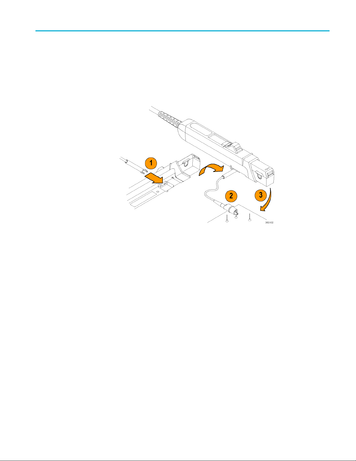
Connect the pr
obe to the amplifier
To connect a current probe to the amplifier input connector, do the following and
refer to the illustration. (See Figure 2.)
1. To connect the probe, align the red dots.
2. Push the probe connector in. Do not twist the connector.
3. To disconnect the probe, pull back the collar.
4. Pull out the connector.
Figure 2: Connecting and disconnecting a current probe to the amplifier
CAUTION. Handle current probes with care. Do not drop a probe or subject it to
ct, or the core may crack.
impa
Do not connect or disconnect a current probe while the probe is clamped around a
ve conductor, or the probe may suffer electrical damage.
li
If you connect a probe to the wrong amplifier, (for example, a TCP312A to a
PA400), the NONCOMPATIBLE PROBE TYPE LED illuminates. Disconnect
TC
the probe and use the correct amplifier. The TCPA400 amplifier accepts
TCP3XXA probes, but will only operate properly with TCP4XX probes.
Each current probe is calibrated before it is shipped, and should not require
further adjustment. If a probe requires adjustment, information is a vailable in the
service manual. The adjustment p rocedure must be performed only by qualified
service personnel. Contact your nearest Tektronix Service Center if you need
more assistan ce.
16 Amplifiers and Current Probes Compliance and Safety Instructions
Page 21

Operate the amplifier
Operate the am
plifier
The TCPA300 a
described below. Some seldom-used functions do not appear in the illustration.
These functions are discussed in the product user manual.
nd TCPA400 front-panel controls and connectors function as
Figure 3: Amplifier front panel (TCPA300 shown)
1. The PROBE DEGAUSS AUTOBALANCE button removes residual
magnetism from the attached current probe. A multi-color LED indicates the
status of the degauss circuit.
2. The MANUAL BALANCE buttons allow you to fine-adjust DC offset from
the amplifier. The adjacent LED lights when one of the buttons has been
pressed.
3. The four probe error lights indicate the following faults: PROBE OPEN,
OVERLOAD (current or temperature), NOT TERMINATED INTO 50 Ω and
ONCOMPATIBLE PROBE TYPE.
N
4. The ON/STANDBY button turns on power to the amplifier.
5. The TCPA300 and TCPA400 output appears at the OUTPUT connector.
Connect this to a 50 Ω input of your oscilloscope.
Amplifiers and Current Probes Compliance and Safety Instructions 17
Page 22

Operate the amplifier
LED indicators
6. The current pro
bes connect to the TCPA300 and TCPA400 at the PROBE
INPUT connector.
7. The COUPLING b
utton selects AC or DC probe coupling, as indicated by
the LEDs.
8. The RANGE bu
tton toggles between the two scale factors that are available
for the attached probe (TCPA300 only). LEDs indicate the selected range.
Indicators Function
PROBE OPEN
OVERLOAD When lit, this LED indicates different overload conditions. (See page 19,
NOT
TERMIN
INTO 50 Ω
NONCOMPATIBLE
PROBE TYPE
ATED
When lit, t
must have the probe slide locked to degauss the probe or to accurately
measure current.
CAUTION:
that the probe slide is locked before you apply power to the circuit.
Overload conditions.)
When lit, this LED indicates that the T EKPROBE Interface able or BNC
cable f
on the oscilloscope. Switch the termination setting on the oscilloscope
to 50 Ω,orusea50Ω termination on the oscilloscope input.
NOTE. N
DEGAUSS AUTOBALANCE operation.
When l
amplifier is not designed to work with the amplifier. TCP3XX probes
only work with the TCPA300 Amplifier, and the TCP404XL probe only
works
his LED indicates that the current probe is unlocked. You
To reduce risk of fire when using bare conductors, ensure
rom the OUTPUT of the amplifier is not connected to a 50 Ω input
OT TERMINATED INTO 50 Ω is only detected during the
it, this LED indicates that the probe that is connected to the
with the TCPA400 Amplifi er.
18 Amplifiers and Current Probes Compliance and Safety Instructions
Page 23

Operate the amplifier
Overload cond
itions
LED color Overload condition Recommended action
Solid red
Flashing
red
Solid
orange
Flashing
red and
orange
All LEDs
flashing
1
Since c
Temperature shifts can also affect the probe accuracy; degauss the probe if the probe head or amplifier
temperature changes more than 5 °C.
Measured continuous
current is exceeding the
continuous current limit of
the probe.
Measured current waveform
has pulses that are
exceeding the limits of
the probe.
The operating temperature
of the probe or the amplifier
has been exceeded.
Both temperature and
current limits have been
exceeded.
Probe & amplifier thermal
shutdown has occurred.
urrent overloads can magnetize the probe, always degauss the probe after an overload condition.
Disconnect the probe from the current
source.
Reduce the current source amplitude or
use a higher probe current range or a
higher-rated current probe.
Disconnect the probe from current
source and allow time for the probe
head and amplifier to cool. Shorten the
measurement time duration or use a
higher-rated current probe.
Disconnect the probe from the current
source. Power-cycle the amplifier and
let the probe and amplifier adequately
cool down (typically 15 m inutes) before
taking measurements again. Shorten
the measurement time duration or use a
higher-rated current probe.
1
WAR NI NG . To avoid personal injury or equipment damage, do not exceed the
specified electrical limits of the TCPA300 and TCPA400 Amplifiers or any
applicable probe accessories.
Amplifiers and Current Probes Compliance and Safety Instructions 19
Page 24

Operate the current probe
Operate the cu
Basic operation
rrent probe
1. Connect the
amplifier.)
2. TCP305A and
(See page 25, Use the ground lead.)
3. Degauss t
probe.)
CAUTION. To prevent inaccurate measurements, always degauss the current probe
before taking measurements.
4. Insert a conductor into the probe. (See page 21, Operate the current probe
slide.)
5. Observe the amplifier and oscilloscope to make measurements.
probe to the amplifier. (See page 16, Connect the probe to the
TCP312A only: If desired, install the ground lead to the probe.
he probe. (See page 24, Degauss and autobalance the current
Operation precautions
WARNING. To prevent risk of electric shock or burn, keep your hands behind the
tactile barrier which indicates the limit of safe access.
CAUTION. To prevent risk of fire, do not connect or disconnect the current probe
to or from a live, uninsulated conductor. The core is not insulated. When you test
insulated circuits, remove power before you connect or disconnect the probe.
un
WARNING. These probes are not rated for bare-wire voltages above 150 V Cat II,
nd insulated-conductor voltages above 300 V Cat II. To reduce risk of electric
a
shock, do not take measurements with these probes on circuits with voltages
above these limits.
NOTE. An insulated conductor is any conductor that is surrounded by an
insulating material that is capable of isolating the voltage present on the
conductor. Lacquer coatings like those typically found on transformer windings
do not provide sufficient, reliable insulation for use with current probes. The
lacquer coating can be easily nicked or damaged, which compromises the
insulating capabilities of the lacquer coating.
20 Amplifiers and Current Probes Compliance and Safety Instructions
Page 25
CAUTION. To prevent damage to the TCP305A & TCP312A probes, do not drop
the probe, sub
insert insulated conductors larger than 5.0 mm (0.2 in) into the probe jaw or
damage may result. If the slider will not close around the conductors, do not
force the slide closed; either reduce the number of conductors, or use a smaller
conductor, if possible, without exceeding the amperage rating of the wire.
CAUTION. To reduce risk of fire, do not connect or disconnect the current probe to
or from a live, uninsulated conductor. The core is not insulated. Always remove
power before you c onnect or disconnect the probe to or from bare conductors.
To improve EMI rejection at high frequencies, use the optional ground lead. Refer
to the TCPA300/400 Amplifiers and TCP300A/400 Series Current Probes User
Manual,
Tektronix part number 077-1183-xx, for additional instructions.
Operate the current probe slide
Operate the current probe
ject it to physical shock or rapid temperature changes, and do not
TCP305A and TCP312A
slide operation
rrent probes each have a slide mechanism that opens and closes the probe
The cu
jaw. This allows you to clamp the probe around a conductor under test. The slide
must be locked closed to accurately measure current or to degauss the probe. If a
probe is unlocked, the PROBE OPEN indicator on the amplifier will light.
The current probes can be used to measure current on uninsulated wires. However,
the circuit must be de-energized when connecting or removing the current probe.
The slide operation of the TCP305A and TCP312A current probes is shown in the
following illustration.
Amplifiers and Current Probes Compliance and Safety Instructions 21
Page 26
Operate the current probe
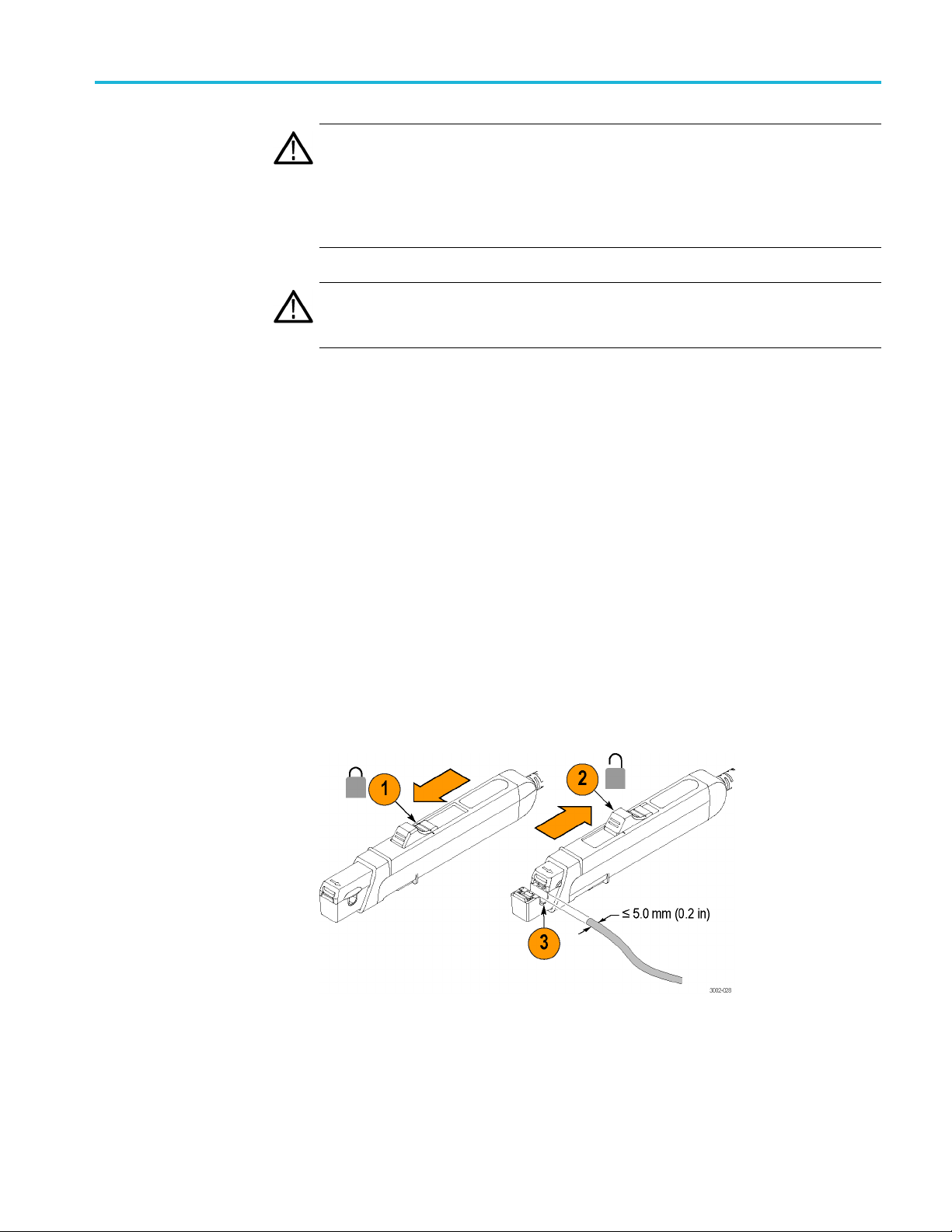
To o perate t he p
1. To close (lock) the probe, push the slide forward until the detent snaps into
place.
NOTE. The slider must be in the closed (locked) position to degauss the probe.
2. To open (unl
3. Insert a 5 mm (0.2 in) diameter maximum conductor size into the jaw.
WARNING.
(0.2 in) diameter into the jaw.
4. Close th
measurements, keep your fingers behind the demarcations on the probe, and
away from the shaded area shown below.
robe:
ock) the probe, pull the slide back until the jaw is open.
To prevent probe damage, do not force conductors larger than 5 mm
e jaw around the conductor and lock the slider. When you are taking
RNING. Do not connect the current probe to any wire that carries voltages or
WA
currents that exceed the rating of the probes.
22 Amplifiers and Current Probes Compliance and Safety Instructions
Page 27
Operate the current probe
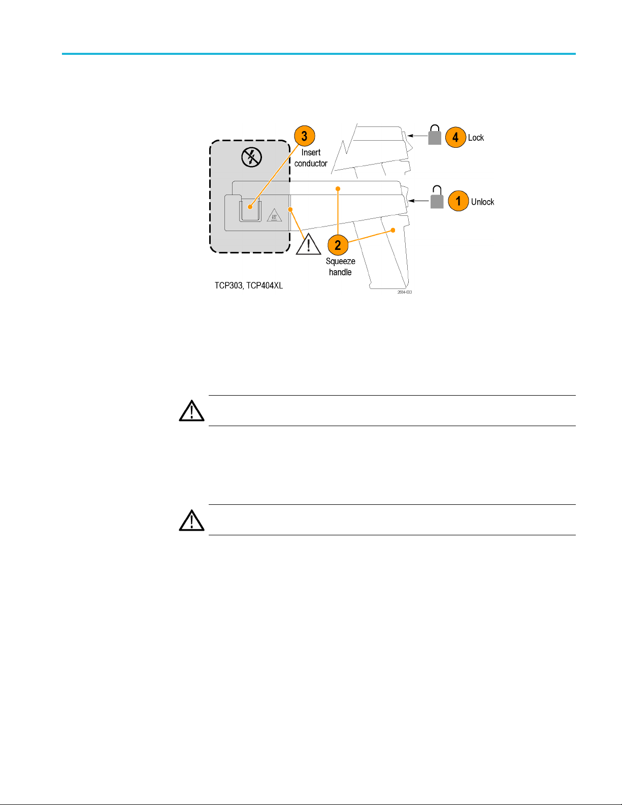
TCP303 and TCP404XL
slide operation
The slide opera
following illustration.
To operate the probe:
1. Press the bottom of the lock button to unlock the probe.
2. Squeeze the handle until the core is open.
3. Insert a 5 mm (0.2 in) diameter maximum conductor size into the jaw.
tion of the TCP303 and TCP404XL current probes is shown in the
WAR NI NG . To prevent probe damage, do not force conductors larger than 5 mm
(0.2 in) diameter into the jaw.
4. To close and lock the probe, release the squeeze handle and press the top of
the lock button. When you are taking measurements, keep your fingers behind
the demarcations on the probe, and away from the shaded area shown above.
WAR NI NG . Do not c onnect the current probe to any wire that carries voltages or
rents that exceed the rating of the probes.
cur
Amplifiers and Current Probes Compliance and Safety Instructions 23
Page 28

Operate the current probe
Degauss and autobalance the current probe
Degauss the probe to remove any residual magnetization from the probe core.
Such residual magnetization can induce measurement error. Autobalancing
removes unwanted DC offsets in the amplifier circuitry. Failure to degauss the
probe is a leading cause of measurement errors. The DEGAUSS LED flashes
until you de
To degauss the probe, disconnect the probe from the test circuit, or ensure that
the conduc
the amplifier PROBE DEGAUSS AUTOBALANCE button on the front panel of
the amplifier. To maintain measurement accuracy, degauss your probe in each of
these cases:
After you turn on the amplifier and allow a 20-minute warm-up period.
Before you connect the probe to a conductor.
gauss the probe.
tor under test has no power, close and lock the slide, and then press
Wheneve
Whenever you connect a new probe.
Whenever you subject the probe to a strong external magnetic field.
Periodically during normal use.
To degauss and autobalance a current probe, perform these steps:
1. Verify that the current probe is connected to the amplifier.
2. Rem
3. Lock the probe slide closed.
4. Press the amplifier PROBE DEGAUSS AUTOBALANCE button.
5. Wait about five seconds for the degauss procedure to complete.
The PROBE DEGAUSS AUTOBALANCE LED glows g reen when the
operation has successfully completed. If the LED is blinking orange, the degauss
operation is still in progress. If the LED is red, the operation failed, and the cause
of the failure needs to be found and fixed. (See page 17, Operate the amplifier.)
NOTE. The degauss procedure will fail if the amplifier is not properly connected
to an oscilloscope having 50 Ω input impedance. If this occurs, the NOT
TERMINATED INTO 50 Ω LED lights on the amplifier front panel.
r a current or thermal overload condition occurs.
ove the current probe from the conductor under test.
After you have completed the oscilloscope adjustments and the amplifier
degauss/autobalance procedure, your system is ready to measure current.
24 Amplifiers and Current Probes Compliance and Safety Instructions
Page 29
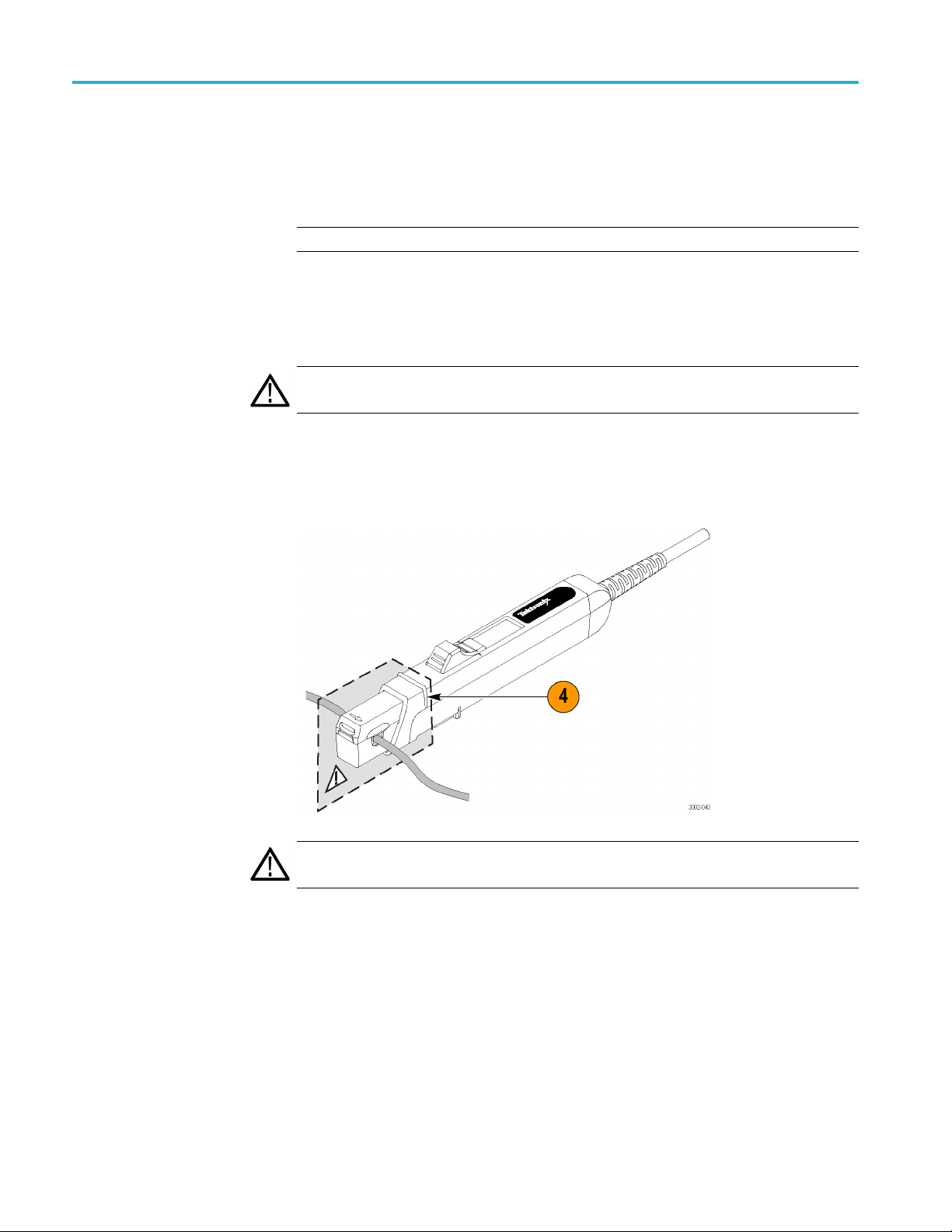
Use the ground lead
Operate the current probe
The TCP305A and TCP312A probes include a 6-inch ground lead. The ground
lead grounds the shield around the probe transformer at the probe end of the
cable. This allows you to move the ground connection closer to the circuit you are
measuring, thereby improving high frequency shielding. The ground lead clips
onto the gro
und connector on the bottom of the probe.
Figure 4: Connecting the ground lead
The ground lead on the current probes is intended to be used in high dV/dt
onments. The probes have a grounded shield between the conductor under
envir
test and the current sense transformer. Any capacitively-coupled current will then
flow in the ground instead of the transformer windings.
When you take high frequency measurements, connect the probe ground lead to
the probe ground connector and attach the alligator clip directly to RF ground to
improve EMI rejection at high frequencies (2 MHz and above). This will reduce
ringing and help bypass capacitively-coupled RF currents which can flow into
the probe cable. In some cases, it may be helpful to move the ground lead or
position the probe away from noise sources in the circuit under test.
re
Amplifiers and Current Probes Compliance and Safety Instructions 25
Page 30
Operate the current probe
Make DC curren
t measurements
To measure DC current, first degauss the probe. (See page 24, Degauss and
autobalance the current probe.)
1. Verify that the amplifier and the oscilloscope input coupling are set to DC,
and the input impedance is set to 50 Ω.
2. Lock the probe closed without a conductor passing through it.
3. Adjust the ground reference of the oscilloscope to move the trace to the
desired graticule line.
4. Press the amplifier PROBE DEGAUSS AUTOBALANCE button.
The NOT TERMINATED INTO 50 Ω LED is lighted if impedance is not
50 Ω. If this is the case , make necessary changes. (For example, use a 50 Ω
termination.)
5. After the degauss/autobalance routine completes, adjust the ground reference
(if necessary) using the amplifier MANUAL BALANCE controls.
WARNING. The current probes can be used to measure current on uninsulated
. However, the circuit must be de-energized when connecting or removing
wires
the current probe.
26 Amplifiers and Current Probes Compliance and Safety Instructions
Page 31
Operate the current probe
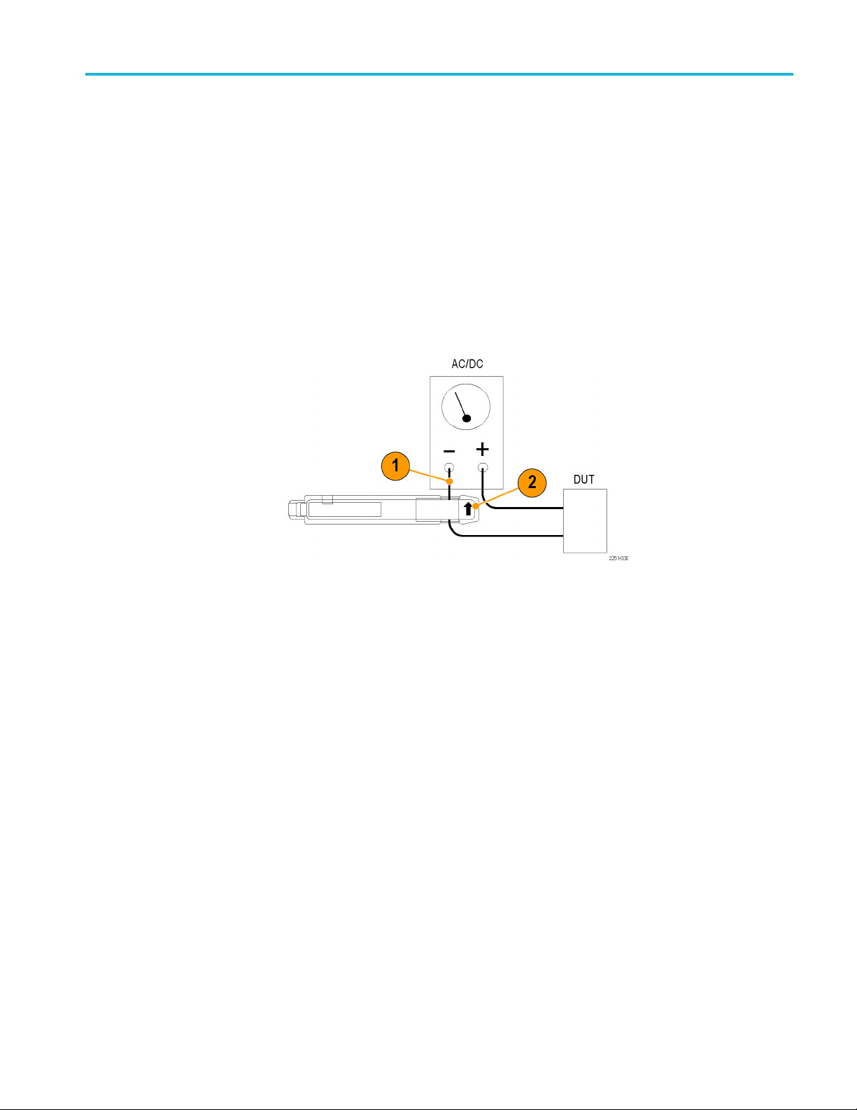
The current pro
Notice that the probe arrow points toward the negative terminal of the power
supplytoconf
To measure DC current, perform these steps:
1. Open the pro
then lock the slide.
2. For correct
the direction of conventional (positive to negative) current flow. Reversing
the flow will display the current waveform upside-down on the oscilloscope.
3. Adjust the oscilloscope time base, trigger, and gain as needed.
be is shown connected to a power supply line. (See Figure 5.)
orm to the conventional current flow of positive (+) to negative (-).
be slide, place the probe around the conductor under test, and
measurement polarity, make sure the probe arrow is pointing in
Figure 5: Arrow on current probe indicates conventional current flow
Amplifiers and Current Probes Compliance and Safety Instructions 27
Page 32

Operate the current probe
Make AC curren
t measurements
To measure AC current only, and remove the DC component of the current being
measured, follow the instructions below. These are identical to the instructions for
DC current me
1. Verify that the oscilloscope input coupling is set to DC, and the input
impedance i
amplifier is lit if impedance is not 50 Ω.)
2. Verify tha
3. Adjust the ground reference of the oscilloscope to move the trace to the
desired g
4. Lock the probe closed without a conductor passing through it, and then press
the ampl
WARNING. The current probes can be used to measure current on uninsulated
wires. However, the circuit must be de-energized when connecting or removing
the current probe.
5. Open the probe slide, place the probe around the conductor under test, and
then lock the slide. For correct measurement polarity, make sure the probe
arrow is pointing in the direction of conventional (positive to negative)
current flow. Reversing the flow will invert the displayed current waveform
on the oscilloscope.
asurements except that the amplifiercouplinginstep2issettoAC.
ssetto50Ω. (The NOT TERMINATED INTO 50 Ω LED on the
t the amplifier input coupling is AC.
raticule line.
ifier PROBE DEGAUSS AUTOBALANCE button.
E. Even when making AC current measurements, leave the oscilloscope
NOT
coupling on DC. Change only the amplifier coupling to AC. Using the oscilloscope
AC coupling may cause the amplifier to exceed its output dynamic range.
6. Adjust the oscilloscope time base and trigger as n eeded.
28 Amplifiers and Current Probes Compliance and Safety Instructions
 Loading...