

Page 1
Installation & Operation Manual
20
Mod Boiler
19
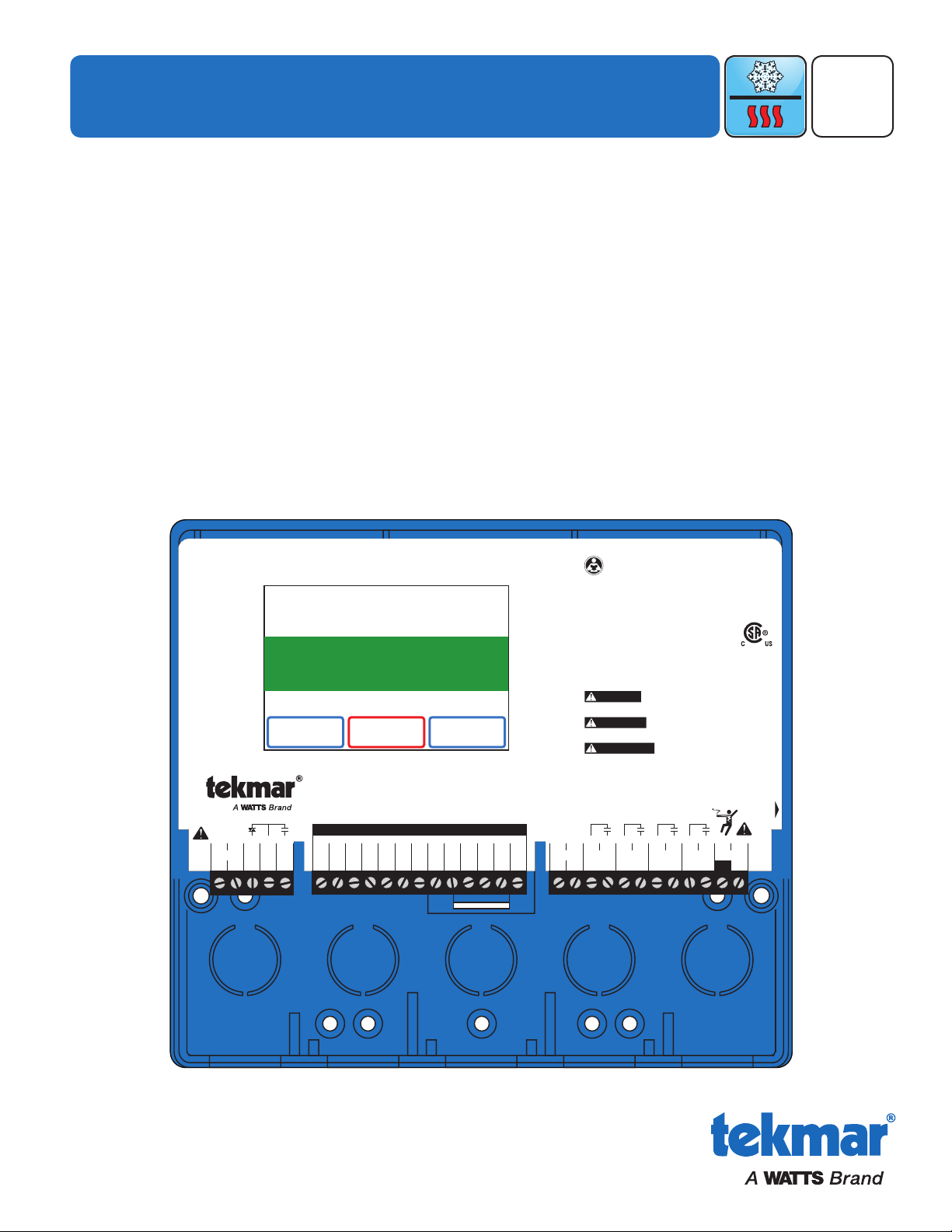
WiFi Snow Melting Control 670
Boiler & Mixing / Electric
Power 115 V (ac) ±10%, 60 Hz, 20 VA
Relays 230 V (ac) 5 A 1/3 hp
Var. Pump 230 V (ac) 2.4 A
1084-01
Designed and assembled in Canada
Date Code
H2055A
1 kΩ max 1 kΩ max
Opn
3
Var2–
Mix V/mA
1
+
Pwr
4
Mix
Cls
5
Blu8Yel9Brn/
10
Slab
Man
11
Melt
C
12
Blk/
7
Com
Red
6
Boiler 1
21
Stage 1
Boiler 1
Stage 2
Heat
Relay
System
Pump–22+
23 24 25
Do Not Apply Power
Mix
15
Sup
Com
16
Boil17Out
18
Com
14
tN4
13 282726
Power
29L30
N
For product literature:
Pour la documentation du produit:
Para la literatura del producto:
tekmarControls.com
Disconnect all power before opening.
WARNING
Coupez l'alimentation avant l'ouverture.
ATTENTION
Desconecte la electricidad antes de abrir.
ADVERTENCIA
Signal wiring must be rated at least 300 V.
Le câblage du signal doit être d'une capacité d'au moins 300 V.
Cableado de señal debe tener una
calificación mínima de 300 V.
Contains WiFi transceiver:
FCC ID: Z64-CC3100M0DR1, IC: 4511-CC3100M0DR1
Meets Class B: FCC Part 15B, ICES-003
Manual Melt
Time Left
- - : - - hrs
Outdoor
32 °F
Settings Status
System is Melting
Stop
10:30 AM
Warming Up
670_D
WiFi Snow Melting Control 670
Snow Melting
10/16
Replaces: New
Introduction
The WiFi Snow Melting Control 670 operates hydronic and electric heating equipment designed to melt snow and/or
ice from roads and walkway surfaces. The control works with the tekmar Snow/Ice Sensor 090 or Snow Sensor 095 to
automatically detect snow or ice and operates a single boiler, steam valve, or electric cable to supply heat to the slab.
Boiler return protection is provided to non-condensing boilers using a mixing valve or variable speed injection mixing
pump. The tekmar Connect mobile application allows for remote operation and monitoring of the snow melting system
from anywhere in the world.
Features
• Mobile app for iOS and Android
• Automatic software updates
• Automatic snow/ice detection
• Supports both inslab & retrofit aerial sensors
• Supports multiple zones with priority
• Idling
• Auto Storm
• Warm Weather Shut Down
• Cold Weather Cut Off
• EconoMelt
• Slab Protection
• Tandem Snow/Ice Detection
• Equipment exercising
© 2016 tekmar 670_D - 10/16
Page 2

Table of Contents
Important Safety Information .............................................3
Installation .........................................................................4
Preparation ....................................................................4
Packaging Contents ......................................................4
Physical Dimensions .....................................................4
Installation Location .......................................................4
Installing the Enclosure ................................................. 5
Rough-In Wiring ............................................................. 6
Sensor Wiring ................................................................ 7
tekmarNet ...................................................................... 9
Manual Melt Input ......................................................... 10
Equipment Wiring .........................................................10
Testing the Sensor Wiring ............................................ 13
Testing the Control Wiring ............................................ 13
Manual Override – Maximum Heat .............................. 14
Manual Override – Purge .............................................14
Manual Override – Test ................................................14
Manual Override – Off .................................................. 14
Access Levels ............................................................... 14
User Interface ...................................................................15
Home Screen ................................................................ 15
System Operation ......................................................... 15
Symbols ........................................................................ 16
Help Screen .................................................................. 16
Status Menu Navigation ............................................... 16
System Status Menu .................................................... 17
Slab Status Screen .......................................................18
Weather Status Screen ................................................ 18
Settings Menu Navigation ............................................ 19
Temp Menu ................................................................... 20
Away Menu ................................................................... 21
Display Menu ................................................................ 21
WiFi Menu ..................................................................... 22
Time Menu .................................................................... 22
Energy Menu ................................................................23
Monitor Menu ................................................................ 24
Setup – System Setup Menu ........................................ 25
Setup – Boiler Setup Menu .......................................... 26
Setup – Mixing Setup Menu .........................................27
tekmarNet Menu ........................................................... 28
Toolbox Menu ...............................................................29
Override Menu ..............................................................30
tekmar Connect Mobile & Web App .................................31
Add Control to App .......................................................31
Account ......................................................................... 32
My Devices ................................................................... 32
Control Operation ......................................................... 33
Energy Usage ............................................................... 33
Sequence of Operation ................................................... 34
Snow Melting Overview ................................................34
Melt – Automatic Start and Stop .................................. 34
Melt – EconoMelt .......................................................... 35
Additional Melting Time ................................................ 35
Melt – Automatic Start and Timed Stop ....................... 35
Tandem Snow/Ice Detection ........................................ 36
Melt – Manual Start and Timed Stop ...........................36
Melt - Tracked Start and Stop ......................................36
Idle Operation ............................................................... 37
Storm Operation ...........................................................37
Slab Temperature Control ............................................ 37
Slab Protection .............................................................38
Warm Weather Shut Down ........................................... 38
Cold Weather Cut Off ................................................... 38
Snow Melt Zones and Priority ...................................... 38
Time Clock .................................................................... 40
Away Operation ............................................................ 40
tekmarNet Scene Operation .........................................40
Application Modes ........................................................ 41
Electric Operation ......................................................... 41
Pulse Width Modulation Zone Operation ..................... 41
Boiler Operation ............................................................ 42
Mixing Operation .......................................................... 43
Boiler and Mixing Operation ......................................... 43
Outdoor Sensor ............................................................43
Exercising ..................................................................... 43
Post Purge .................................................................... 43
Troubleshooting ............................................................... 44
Error Messages (1 of 4) ................................................ 44
Error Messages (2 of 4) ................................................ 45
Error Messages (3 of 4) ................................................ 46
Frequently Asked Questions ........................................ 47
Technical Data ................................................................. 48
Limited Warranty and Product Return Procedure ........... 48
Getting Started
Congratulations on the purchase of your new Snow Melting Control!
This manual covers the complete installation, programming and sequence of operation for this control. You will also find
instruction on testing, commissioning, and troubleshooting the control and system that it operates.
© 2016 tekmar 670_D - 10/16
2 of 48
Page 3
Important Safety Information
It is your responsibility to ensure that this control is safely installed according to all applicable codes and standards. tekmar is
not responsible for damages resulting from improper installation and/or maintenance.
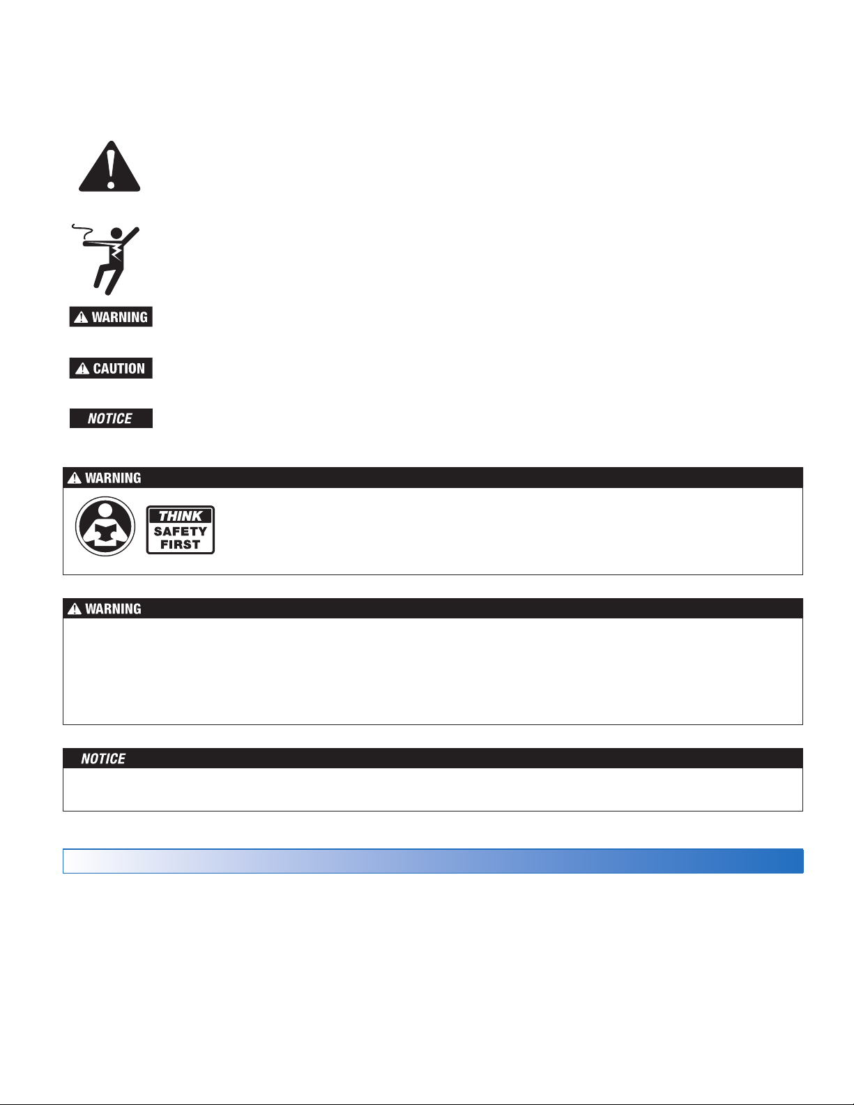
This is a safety-alert symbol. The safety alert symbol is shown alone or used with a signal word (DANGER,
WARNING, or CAUTION), a pictorial and/or a safety message to identify hazards. When you see this symbol
alone or with a signal word on your equipment or in this manual, be alert to the potential for death or serious
personal injury.
This pictorial alerts you to electricity, electrocution, and shock hazards.
This symbol identifies hazards which, if not avoided, could result in death or serious injury.
This symbol identifies hazards which, if not avoided, could result in minor or moderate injury.
This symbol identifies practices, actions, or failure to act which could result in property damage or damage to
the equipment.
Read manual and all product labels BEFORE using the equipment. Do not use unless you know
the safe and proper operation of this equipment. Keep this manual available for easy access by all
users. Replacement manuals are available at tekmarControls.com
•
It is the installer’s responsibility to ensure that this control is safely installed according to all applicable codes and
standards.
•
Improper installation and operation of this control could result in damage to the equipment and possibly even personal
injury or death.
• This control is not intended for use as a primary limit control. Other controls that are intended and certified as safety limits
must be placed into the control circuit.
Do not attempt to service the control. There are no user serviceable parts inside the control. Attempting to service the control
voids the warranty.
Radio Frequency Interference
The installer must ensure that this control and its wiring are
isolated and/or shielded from strong sources of electromagnetic
noise. Conversely, this Class B digital apparatus complies
with Part 15 of the FCC Rules and meets all requirements of
the Canadian Interference-Causing Equipment Regulations.
However, if this control does cause harmful interference to
radio or television reception, which is determined by turning
the control off and on, the user is encouraged to try to correct
the interference by re-orientating or relocating the receiving
antenna, relocating the receiver with respect to this control,
and/or connecting the control to a different circuit from that
to which the receiver is connected.
Cet appareil numérique de la classe B respecte toutes les exigences du Règlement sur le matériel brouilleur du Canada.
3 of 48
© 2016 tekmar 670_D - 10/16
Page 4
Installation
20
Mod Boiler
19
WiFi Snow Melting Control 670
Boiler & Mixing / Electric
Power 11 5 V (ac) ±10%, 60 Hz, 20 VA
Relays 230 V (ac) 5 A 1/3 hp
Var. Pump 230 V (ac) 2.4 A
1084-01
Designed and assembled in Canada
Date Code
H2055A
1 kΩ max 1 kΩ max
Opn
3
Var2–
Mix V/mA
1
+
Pwr
4
Mix
Cls
5
Blu8Yel9Brn/
10
Slab
Man
11
Melt
C
12
Blk/
7
Com
Red
6
Boiler 1
21
Stage 1
Boiler 1
Stage 2
Heat
Relay
System
Pump–22+
23 24 25
Do Not Apply Power
Mix
15
Sup
Com
16
Boil17Out
18
Com14tN4
13 282726
Power
29L30
N
For product literature:
Pour la documentation du produit:
Para la literatura del producto:
tekmarControls.com
Disconnect all power before opening.
WARNING
Coupez l'alimentation avant l'ouverture.
ATTENTION
Desconecte la electricidad antes de abrir.
ADVERTENCIA
Signal wiring must be rated at least 300 V.
Le câblage du signal doit être d'une capacité d'au moins 300 V.
Cableado de señal debe tener una
calificación mínima de 300 V.
Contains WiFi transceiver:
FCC ID: Z64-CC3100M0DR1, IC: 4511-CC3100M0DR1
Meets Class B: FCC Part 15B, ICES-003
Manual Melt
Time Left
- - : - - hrs
Outdoor
32 °F
Settings Status
System is Melting
Stop
10:30 AM
Warming Up
Preparation
Tools Required
-----------------------------------------------------------------------------------------
• tekmar or jeweler screwdriver
• Phillips head screwdriver
Materials Required
-------------------------------------------------------------------------------------
• 18 AWG LVT solid wire (low-voltage connections)
• 14 AWG solid wire (line-voltage connections)
Packaging Contents
The following are included in the product packaging:
• 1 WiFi Snow Melting Control 670
• 3 Universal Sensor 082
• 1 Outdoor Sensor 070
• 1 screwdriver
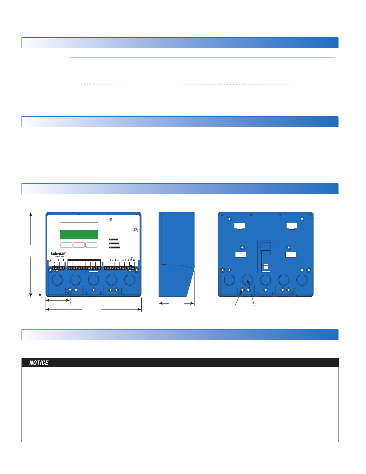
Physical Dimensions
Front View
Side View
• Needle-nose pliers
• Wire stripper
• Four 1/8" - 1" wood screws
• 1 Application Brochure 670_A
• 1 Installation and Operation Manual 670_D
• 1 User Manual 670_U
Mounting Base
1/2"
(13 mm)
CL
7/8"
(23 mm)
6–5/8"
(170 mm)
1/2"
(14 mm)
1–7/8" (49 mm)
7–5/8"
2–7/8"
(72 mm)
3/16" (5 mm)
(193 mm)
Installation Location
Choose the placement of the control early in the construction process to enable proper wiring during rough-in.
• Keep the control dry. Avoid potential leakage onto the control.
• Maintain relative humidity less than 90% in a non-condensing environment.
• Avoid exposure to extreme temperatures beyond 32-122°F (0-50°C).
• Install away from equipment, appliances, or other sources of electrical interference.
• Install to allow easy access for wiring, viewing, and adjusting the display screen.
• Install approximately 5 feet (1.5 m) off the finished floor.
• Locate the control near pumps and/or zone valves if possible.
• Provide a solid backing which the enclosure can be mounted to. Example: plywood or wall studs.
© 2016 tekmar 670_D - 10/16
• Use the conduit knockouts provided on the upper, lower, back and sides of the enclosure for wiring.
4 of 48
1/2" Knock-out
(x 5 back) (x 5 bottom)
Page 5
Installing the Enclosure
• Install the control enclosure to a wall or to an electrical box.
•
Three wiring chamber dividers are included. The dividers provide a barrier to keep low voltage wiring separated from line
voltage wiring.
• If the dividers are not used, then low voltage circuits must use wire rated at least 300 V.
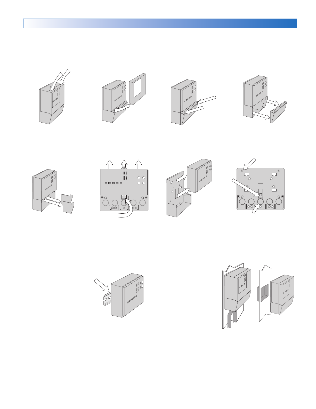
Press down at the fingertip
grips
on top of the front cover
and pull
out and down.
Remove the safety dividers
from the wiring chamber by
pulling them straight out of
their grooves.
The control can be mounted on
a standard DIN rail. First remove
the control from its base and then,
using the hooks and spring clip
on the back of the control, mount
it onto the DIN rail. This will be a
popular option for those who prefer
to mount the control inside a larger
electrical panel. The DIN Snap Kit
M9303 is sold separately.
Lift the front cover up and
away
from the control.
Control release clip
Press the control release clip
on the base inside the wiring
chamber and slide the control
upwards.
Loosen the screws at the
front of the wiring cover.
from the base.
The wiring can enter the
bottom or the back of the
enclosure. Knock-outs provided in the base allow the
wiring to be run in conduit
up to the enclosure. The
base also has holes that
line up with the mounting
holes of most common
electrical boxes.
The wiring cover pulls straight
out from the wiring chamber.
13 Mounting holes
Control
release
clip
There are 10 conduit knock-outs at the back
and bottom of the wiring chamber.
The base is ready for mounting.The control lifts up and away
5 of 48
© 2016 tekmar 670_D - 10/16
Page 6
Rough-In Wiring
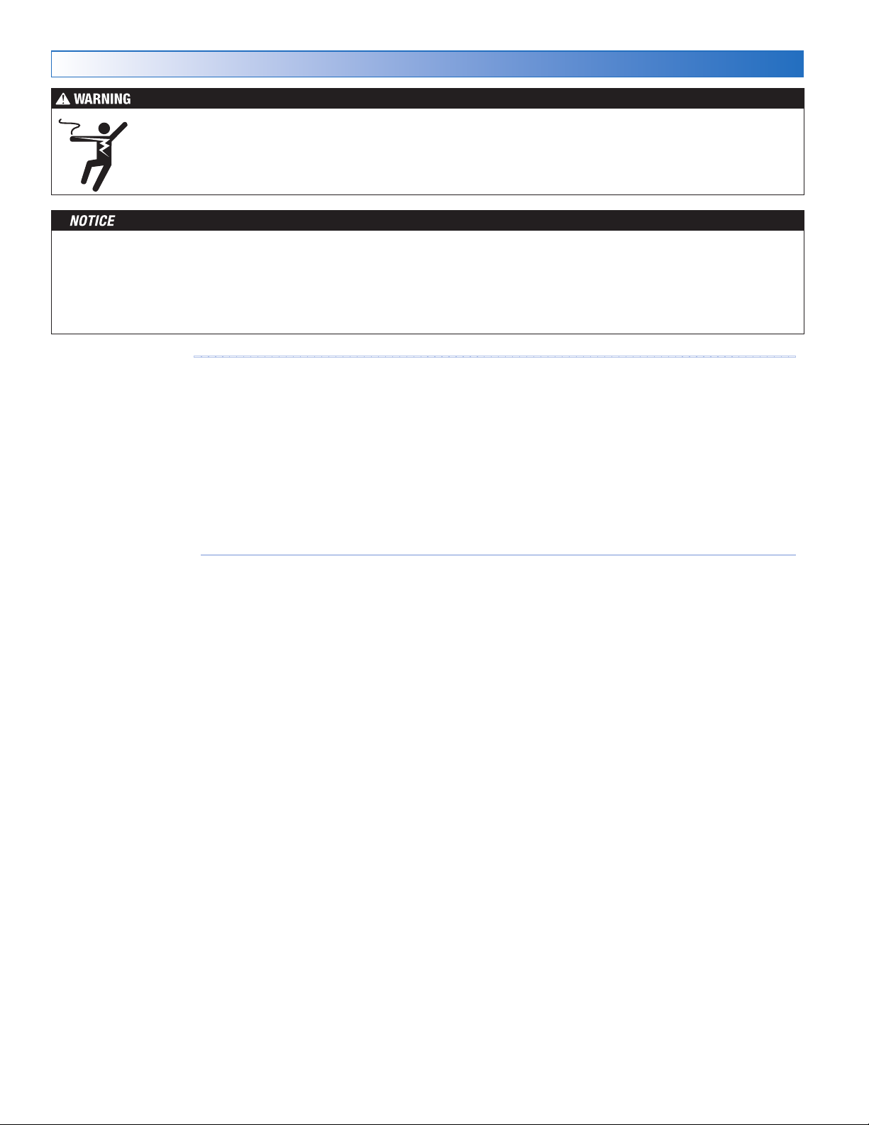
To prevent the risk of personal injury and/or death, make sure power is not applied to the control until it is fully
installed and ready for final testing. All work must be done with power to the circuit being worked on turned off.
Please be aware local codes may require this control to be installed or connected by an electrician.
•
Install the supplied wiring compartment barriers by sliding them into the grooves provided to isolate the low and linevoltage wiring.
• Strip all wiring to a length of 3/8 in. or 10 mm for all terminals.
• A circuit breaker or power disconnect that provides power to the control should be located nearby and clearly labeled.
• Refer to the current and voltage ratings at the back of this manual before connecting devices to this control.
Low-Voltage Wiring
Pull two conductor 18 AWG LVT cable, up to 500 feet
(150 m) long, for the following equipment:
• Outdoor temperature sensor
• Mix supply sensor
• Boiler sensor
• Single-stage on/off boiler
• Modulating boiler 0-10 V (dc) or 4-20 mA
•
Mixing valve or mixing injection pump using a 0-10 V (dc)
or 4-20 mA signal.
Line-Voltage Wiring
Pull two conductor 14 AWG cable, up to 500 feet
(150 m) long, for the following equipment:
• System pump
• Boiler pump
• Heat exchanger on/off injection pump
• Variable speed injection pump
-------------------------------------------------------------------------------------
------------------------------------------------------------------------------------
Pull three conductor 18 AWG LVT cable, up to 500 feet
(150 m) long, for the following equipment:
• Mixing valves using a floating action signal
Pull four conductor 18 AWG LVT cable, up to 500 feet
(150 m) long, for the following equipment:
• Snow Sensor 095
• Two-stage on/off boiler
Pull the Snow/Ice Sensor 090 or 094 cable to the control.
© 2016 tekmar 670_D - 10/16
6 of 48
Page 7

Sensor Wiring
16
17
18
Mounting the Outdoor Sensor
--------------------------------------------------------------------------
• The temperature sensor (thermistor) is built into the sensor
enclosure.
• The outdoor sensor can either be mounted directly onto a
wall and the wiring should enter through the back or bottom
of the enclosure. Do not mount the outdoor sensor with the
conduit knockout facing upwards because rain could enter
the enclosure and damage the sensor.
S1
S1
Remove
cover by
sliding up-
wards away
from the
base.
If using
conduit,
remove the
flexible plug
from the
base bottom.
S1
S1
S1
S1
To wire from
the back,
remove the
knock-out in
the sensor
base.
Attach the
base to the
wall, soffit
or electrical
box.
•
In order to prevent heat transmitted through the wall from
affecting the sensor reading, it may be necessary to install
an insulating barrier behind the enclosure.
•
The outdoor sensor should be mounted on a north-facing
wall. The outdoor sensor should not be exposed to heat
sources such as ventilation or window openings.
•
The outdoor sensor should be installed at an elevation above the
ground that will prevent accidental damage or tampering.
Wiring the Outdoor Sensor
•
Connect 18 AWG or similar wire to the two terminals provided
-----------------------------------------------------------------------------
in the enclosure and run the wires from the outdoor sensor
to the control. Do not run the wires parallel to telephone or
power cables. If the sensor wires are located in an area
with strong sources of electromagnetic interference (EMI),
shielded cable or twisted pair should be used or the wires
can be run in a grounded metal conduit. If using shielded
cable, the shield wire should be connected to the Com terminal on the control and not to earth ground.
•
Follow the sensor testing instructions in this manual and
connect the wires to the control.
• Replace the front cover of the sensor enclosure.
At the control:
• Connect the outdoor sensor to terminals 16 and 18.
S1
S1
Wires from
outdoor sensor
and sensor
common
terminals on
tekmar control
Out
Boil
Com
7 of 48
© 2016 tekmar 670_D - 10/16
Page 8
Mounting the Boiler and System Sensors
16
17
15
14
--------------------------------------------------------------
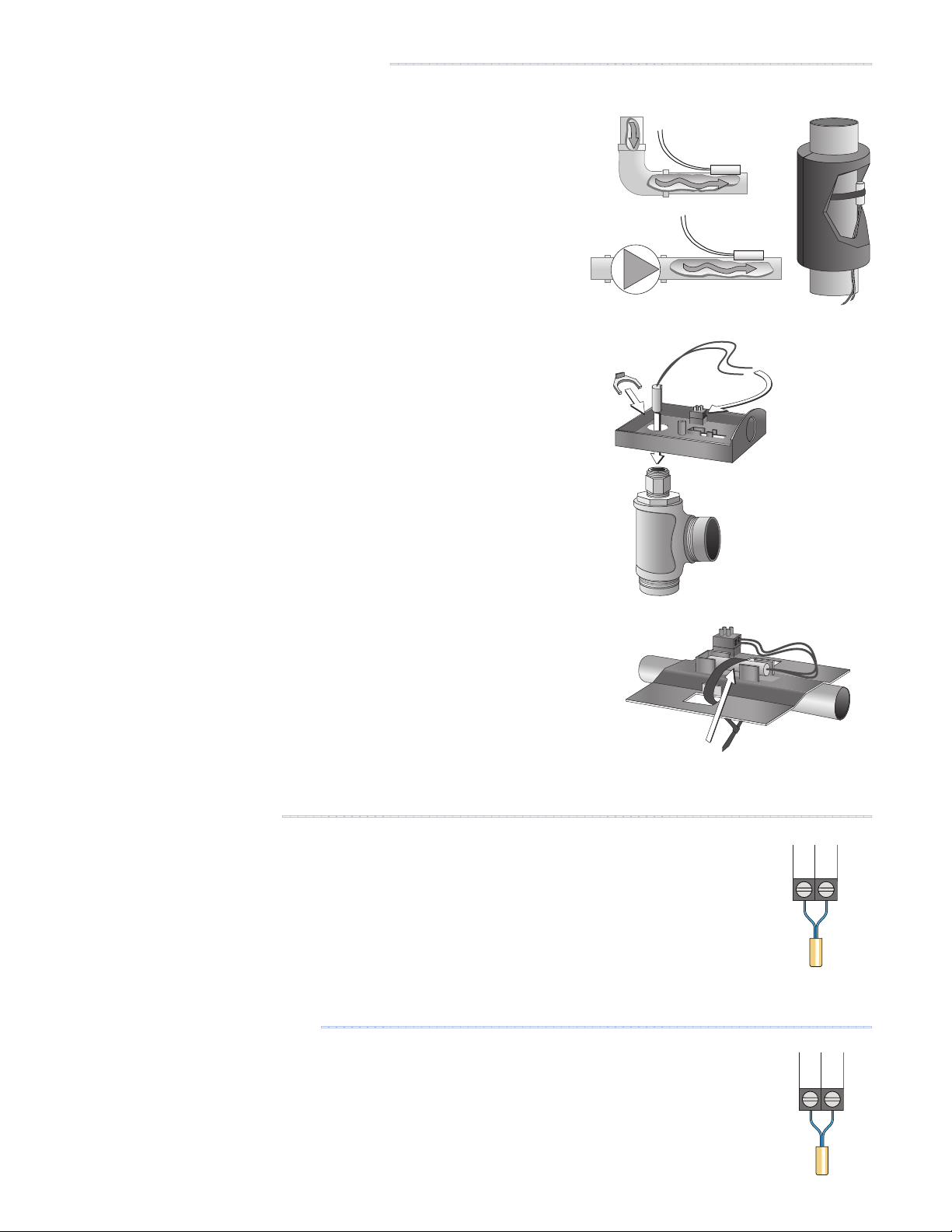
The Universal Sensor 082 is designed to mount on a pipe or in a temperature
immersion well. The sensor should be placed downstream of a pump or after
an elbow or similar fitting. This is especially important if large-diameter pipes
are used as the thermal stratification within the pipe can result in erroneous
sensor readings. Proper sensor location requires that the fluid is thoroughly
mixed within the pipe before it reaches the sensor.
Strapped to Pipe
The Universal Sensor can be strapped directly to the pipe using the cable tie
provided. Insulation should be placed around the sensor to reduce the effect
of air currents on the sensor measurement.
Immersion Well
If a Universal Sensor is mounted onto 1" (25 mm) diameter L type copper pipe,
there is approximately an 8 second delay between a sudden change in water
temperature and the time the sensor measures the temperature change. This
delay increases considerably when mild steel (black iron) pipe is used. In general,
it is recommended that a temperature well be used for steel pipe of diameter
greater than 1-1/4" (32 mm). Temperature wells are also recommended when
large diameter pipes are used and fluid stratification is present.
Conduit Connection
The Universal Sensor and Universal Sensor Enclosure 080 (sold separately) are
specifically designed to mount onto a 3/8" (10 mm) ID temperature well that is
supplied with an end groove. To install the well, plumb a tee into the pipe and fix
the well into the tee. The 080 enclosure has a 7/8" (22 mm) back knockout that
must be removed and fitted over the temperature well. The universal sensor is
then inserted into the well and the retaining clip supplied with the enclosure is
snapped onto the well end groove. If the well has a threaded end, the installer
must supply a standard threaded conduit retaining ring. The two wires from the
sensor are connected to the terminal block provided in the enclosure. The other
side of the terminal block is used to connect wires from the control.
Retaining
Clip
Universal
Sensor
Sensor Well
Universal
Sensor
Bottom of
Enclosure 080
Cable Tie
Mounting the Boiler Sensor
----------------------------------------------------------------------------
The boiler sensor is used when operating a boiler.
• If applicable, connect the boiler sensor to terminals 16 and 17.
Mounting the Mix Supply Sensor
-----------------------------------------------------------------------
The mix supply sensor is used when operating a mixing valve or a variable
speed injection pump is installed.
• If applicable, connect the mix supply sensor to terminals 14 and 15.
© 2016 tekmar 670_D - 10/16
8 of 48
Com
Com
Boil
Mix
Sup
Page 9
Snow/Ice Sensor
10
Slab
7
Com
6
10
7
6
10
Slab
7
Com
6
11C12
---------------------------------------------------------------------------------------
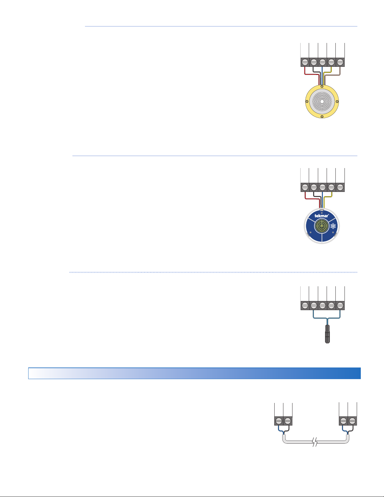
A Snow/Ice Sensor 090 or 094 can be connected to the control. The 090 has
a 65' (20 m) cable and the 094 has a 208' (63 m) cable. The cable may be
extended to a total length of 500' (150 m) using 18 AWG cable. Any junction
boxes must kept dry.
If the Snow/Ice Sensor input is used:
• Connect the red wire to terminal 6.
• Connect the black wire to terminal 7.
• Connect the blue wire to terminal 8.
• Connect the yellow wire to terminal 9.
• Connect the brown wire to terminal 10.
Red
Blk/
Blu8Yel9Brn/
Snow Sensor
-------------------------------------------------------------------------------------------
A Snow Sensor 095 can be connected to the control.
If the Snow Sensor input is used:
• Connect the red wire to terminal 6.
• Connect the black wire to terminal 7.
• Connect the blue wire to terminal 8.
• Connect the yellow wire to terminal 9.
Slab Sensor
--------------------------------------------------------------------------------------------
A Slab Sensor 072 or 073 can be installed either alone or together with a Snow
Sensor 095.
If the Slab Sensor input is used:
Connect the slab sensor to terminals 7 and 10.
Red
Red
Snow
Sensor
Blk/
Com
095
Blk/
Blu8Yel9Brn/
Slab
Blu8Yel9Brn/
tekmarNet
The 670 can be connected to other tekmarNet communication compatible controls
using the tN4 bus.
If tekmarNet is used:
•
Connect tN4 on the 670 terminal 11 to the tN4 wiring terminal on the other device.
• Connect C on the 670 terminal 12 to the C wiring terminal on the other device.
• tekmarNet is polarity sensitive.
9 of 48
tN4
670
other tN4
control
tN4
C
© 2016 tekmar 670_D - 10/16
Page 10
Manual Melt Input
Melt
1413
2
–
1
+
3
Var
4
Mix
5
L
N
G
3
4
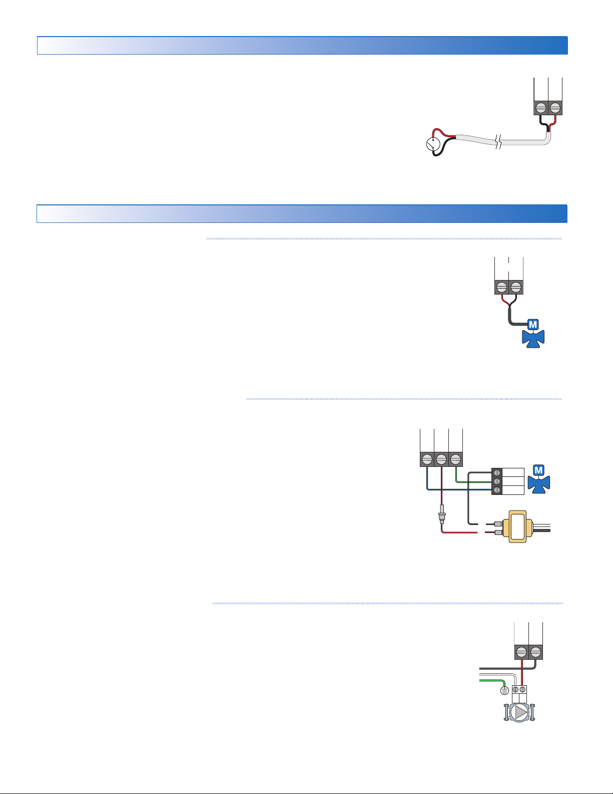
The manual melt input allows the control to be manually switched to melting
operation using a switch. This connection is optional.
If the Manual Melt input is used:
Connect a switch to terminals 13 and 14. The switch may be either dry (no voltage)
or a voltage signal up to 32 V (ac).
Equipment Wiring
Man
Com
Wiring the Analog Mixing Output
-----------------------------------------------------------------------
The control can operate a mixing valve by providing a 0-10 V (dc) or a 4-20
mA signal to the valve actuating motor.
• If applicable, connect the mixing actuator positive (+) to terminal 1.
• If applicable, connect the mixing actuator negative (-) to terminal 2.
Wiring the Floating Action Mixing Output
---------------------------------------------------------------
The control provides a floating action signal to operate a floating action actuator. The
floating action mixing output uses dry relay contacts that can switch either 24, 120, or
230 V (ac). When using 24 V (ac), a Transformer 009 is required to power the actuator.
The actuator terminals are typically labeled for clockwise and counterclockwise rotation.
The control's open and close terminals are wired to the actuator depending on the
direction the valve rotates to open and close respectively.
• Connect the power source to the Pwr terminal 4 on the control.
• Connect the Opn terminal 3 to the actuator terminal that rotates the valve open.
• Connect the Cls terminal 5 to the actuator terminal that rotates the valve close.
• If using a 24 V (ac) transformer, connect the actuator common to the transformer C.
• If using a 120 V or 230 V (ac) power supply, connect the actuator common to the
power supply neutral (N).
Opn
Pwr
Cls
Mix V/mA
Com
Close
Open
C
R
N
L
Wiring the Injection Mixing Pump
A variable speed injection mixing pump requiring up to
operated through terminals 3 and 4. For simplicity in wiring and troubleshooting,
a separate breaker for the pump is recommended.
----------------------------------------------------------------------
230 V (ac), 2.4 A
is
Opn
Var
Pwr
Mix
• Connect 115 or 230 V (ac) power L to the Pwr Mix terminal 4.
• Connect a wire from Var terminal 3 to the pump L.
• Connect a wire from the pump N to the power Neutral.
• Connect the ground wire (G) to the pump.
© 2016 tekmar 670_D - 10/16
10 of 48
NG
L
Page 11
Modutrol IV™
Wiring to a Modulating Boiler
Actuating
21
22
20
Mod Boiler
19
21
Stage 1–22+
21
22 23 24
---------------------------------------------------------------------------
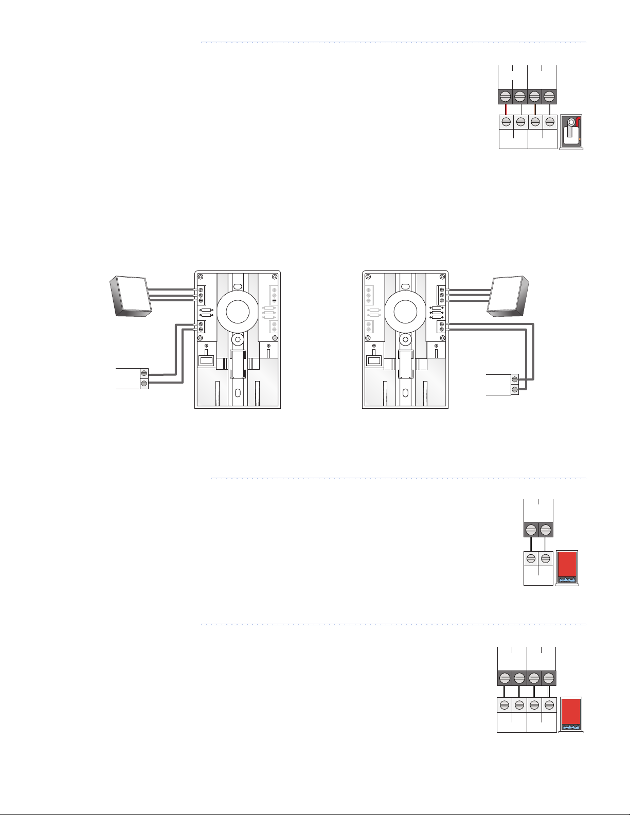
The control provides either a 4-20 mA or a 0-10 V (dc) output to the boiler. Polarity must be
observed.
• Connect the Mod + terminal from the boiler to terminal 19.
• Connect the Mod - terminal from the boiler to terminal 20.
• Some modulating boilers require an enable to start firing the boiler. Connect the boiler enable to
the stage 1 terminals 21 and 22.
Boiler 1
-
TT+
Mod Enable
The 4 to 20 mA output can be converted to a 0 - 135 Ω output
for a Modutrol IV™ gas valve actuating motor using a 0 - 135 Ω
tekmar Converter 005 (sold separately).
Modutrol IV V9055
0 - 135 Ω
Actuating
Motor
Snow
Melting
Control
Mod
B
R
W
+
-
Modutrol IV
tekmar
B
R
W
+
-
670
Modutrol IV™ and V9055™ are trademarks of Honeywell, Inc.
Wiring to a Single-Stage Boiler
-------------------------------------------------------------------------
V9055
B
R
W
+
-
tekmar
A single-stage boiler is enabled through the T-T contacts.
• Connect Stage 1 terminals 21 and 22 to the boiler T-T contacts.
The 4 to 20 mA output can be converted to a 0 - 135 Ω output
for a V9055™ gas valve actuating motor using a 0 - 135 Ω
tekmar Converter 005 (sold separately).
Modutrol IV
tekmar
B
R
W
+
-
V9055
B
R
W
+
-
tekmar
Mod
B
R
W
V9055™
0 - 135
Motor
Ω
Snow
+
-
Melting
Control
670
Boiler 1
Stage 1
Wiring to a Two-Stage Boiler
---------------------------------------------------------------------------
A two-stage boiler is enabled through the T-T contacts.
• Connect Stage 1 terminals 21 and 22 to the boiler's stage 1 contacts.
• Connect Stage 2 terminals 23 and 24 to the boiler's stage 2 contacts.
11 of 48
TT
Stage 1
Boiler 1
Boiler 1
Stage 1
Stage 2
TT
TT
Stage 2
Stage 1
© 2016 tekmar 670_D - 10/16
Page 12
WR
29
L30N
Wiring the Heat Relay
Relay
25
26
R
C
25
26
25
26
Pump
2827
----------------------------------------------------------------------------------
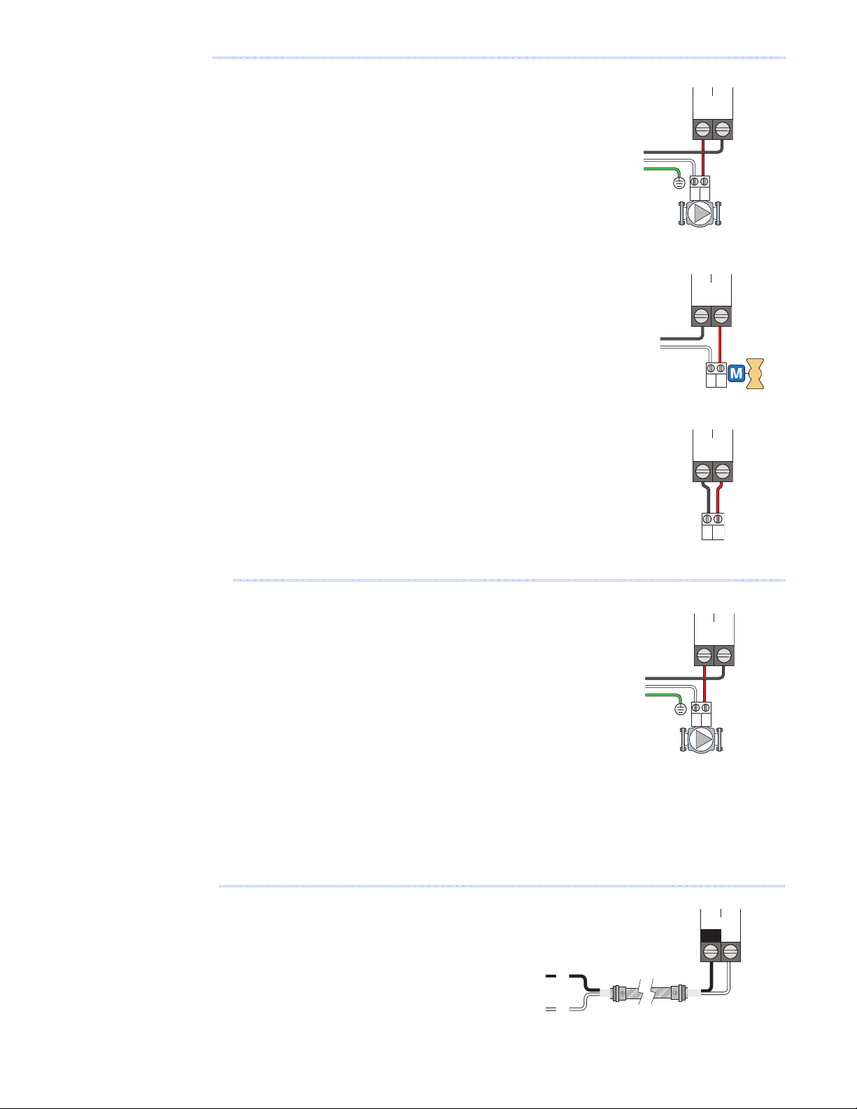
If the heat relay is operating a pump:
The pump can be rated up to
230 V (ac), 5 A, 1/3 hp
and switched through
terminals 25 and 26. For simplicity in wiring and troubleshooting, a separate
breaker for each pump is recommended.
• Connect the power source line wire (L) to terminal 26.
• Connect a wire from terminal 25 to the pump L.
• Connect a wire from the pump N back to the power source neutral.
• Connect the ground wire (G) to the pump.
If the heat relay is wired to a 24 V(ac) on-off valve:
• Connect the power source red wire (R) to terminal 25.
• Connect a wire from terminal 26 to the valve R.
• Connect a wire from the valve C to the power source common.
If the heat relay is wired to an electrical contactor:
• Connect a wire from terminal 25 to the electrical contactor R.
• Connect a wire from terminal 26 to the electrical contactor C.
Heat
L
N
G
NG
L
Heat
Relay
RC
Heat
Relay
Wiring the System Pump
A system pump requiring up to
-------------------------------------------------------------------------------
230 V (ac), 5 A, 1/3 hp
can be switched through
terminals 27 and 28. For simplicity in wiring and troubleshooting, a separate
breaker for each pump is recommended.
• Connect the power source line wire (L) to terminal 28.
• Connect a wire from terminal 27 to the pump L.
• Connect a wire from the pump N back to the power source neutral.
• Connect the ground wire (G) to the pump.
Wiring the Input Power
---------------------------------------------------------------------------------
Provide a 15 A circuit for the input power.
• Connect the 115 V (ac) line wire (L) to terminal 29.
• Connect the neutral wire (N) to terminal 30.
System
L
N
G
NG
L
Power
L
© 2016 tekmar 670_D - 10/16
N
12 of 48
Page 13
Testing the Sensor Wiring
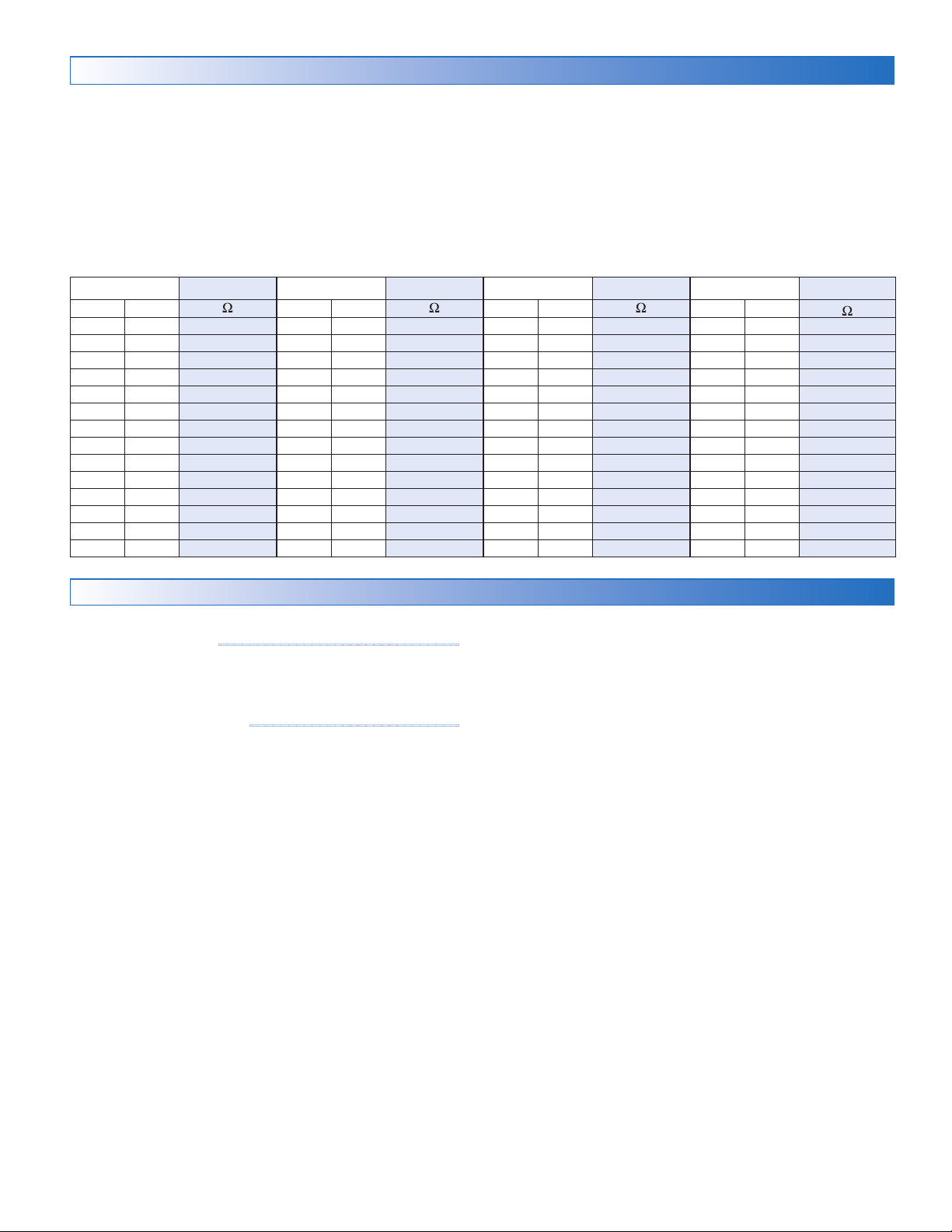
A good quality test meter capable of measuring up to 5,000 kΩ
(1 kΩ = 1000 Ω) is required to measure the sensor resistance.
In addition, the actual temperature must be measured with
either a high-quality digital thermometer, or if a thermometer
is not available, a second sensor can be placed alongside
the one to be tested and the readings compared.
First, measure the temperature using the thermometer and
then measure the resistance of the sensor at the control. The
wires from the sensor must not be connected to the control
while the test is performed. Using the chart below, estimate
Temperature Resistance Temperature Resistance Temperature Resistance Temperature Resistance
°F °C
-50 -46 490,813 20 -7 46,218 90 32 7,334 160 71 1,689
-45 -43 405,710 25 -4 39,913 95 35 6,532 165 74 1,538
-40 -40 336,606 30 -1 34,558 100 38 5,828 170 77 1,403
-35 -37 280,279 35 2 29,996 105 41 5,210 175 79 1,281
-30 -34 234,196 40 4 26,099 110 43 4,665 180 82 1,172
-25 -32 196,358 45 7 22,763 115 46 4,18 4 185 85 1,073
-20 -29 165,18 0 50 10 19,900 120 49 3,760 190 88 983
-15 -26 139,403 55 13 17, 436 125 52 3,383 195 91 903
-10 -23 118,018 60 16 15, 311 130 54 3,050 200 93 829
-5 -21 100,221 65 18 13,474 135 57 2,754 205 96 763
0 -18 85,362 70 21 11,883 140 60 2,490 210 99 703
5 -15 72,918 75 24 10,501 145 63 2,255 215 102 648
10 -12 62,465 80 27 9,299 150 66 2,045 220 104 598
15 -9 53,658 85 29 8,250 155 68 1,857 225 107 553
°F °C °F °C °F °C
the temperature measured by the sensor. The sensor and
thermometer readings should be close. If the test meter reads
a very high resistance, there may be a broken wire, a poor
wiring connection or a defective sensor. If the resistance is
very low, the wiring may be shorted, there may be moisture
in the sensor or the sensor may be defective. To test for
a defective sensor, measure the resistance directly at the
sensor location.
Do not apply voltage to a sensor at any time as damage
to the sensor may result.
Testing the Control Wiring
Remove the front cover from the control.
Testing the Power
• Use an electrical meter set to measure (ac) voltage.
• Measure between the L and N terminals.
• The reading should be 115 V (ac) +/– 10%.
Hand Manual Override
The control includes a Hand Manual Override menu to check
if the control’s relays are operating and that the control is wired
correctly to the snow melting equipment.
Step 1:
Step 2:
Step 3:
Step 4:
Step 5:
Step 6:
• System Pump relay
• Heat Relay
• Boiler Stage 1 relay
• Boiler Stage 2 relay
• Boiler Modulation 0-10 V (dc) or 4-20 mA signal
• Mix System Output 0-10 V (dc) or 4-20 mA signal
• Mix System Output floating action relays
• Mix System Output variable-speed injection pump
Press Settings button.
Press Override button.
Press Manual Override.
Select Manual Override to Hand.
Press Back button.
The following outputs can be operated:
-------------------------------
---------------------------
For each relay output
• Use an electrical meter set to measure (ac) voltage.
• Measure between the relay wiring terminals.
• When the relay is off, the voltage should be 115 V (ac).
• When the relay is on, the voltage should be 0 V (ac).
For the Boiler Modulation
• Use an electrical meter set to measure V (dc) or mA.
• Set the Boiler Modulation to 100%.
•
The voltage between the + and – wiring terminals should be
10 V (dc) or 20 mA.
• Set the Boiler Modulation to 0%.
•
The voltage between the + and – wiring terminals should be
0 V (dc) or 4 mA.
For the Mix System Output – Floating Action
• Use an electrical meter set to measure (ac) voltage.
• Set the Mix Output to 100%. The floating action open wiring
terminal will be closed for the length of the motor speed set
ting (default is 105 seconds).
• When opening, the voltage between the open and common
wiring terminals should be 24 V (ac) or 115 V (ac).
•
When opening, the voltage between the close and common
wiring terminals should be 0 V (ac).
• Set the Mix Output to 0%. The floating action closed wiring
terminal will be closed for the length of the motor speed set
ting (default is 105 seconds).
•
When closing, the voltage between the open and common
wiring terminals should be 0 V (ac).
• When closing, the voltage between the close and common
wiring terminals should be 24 V (ac) or 115 V (ac).
-
-
13 of 48
© 2016 tekmar 670_D - 10/16
Page 14

For the Mix Output – Analog Mixing
• Use an electrical meter set to measure V (dc) or mA.
• Set the Mix Output to 100%.
•
The voltage between the + and – wiring terminals should be
10 V (dc) or 20 mA.
• Set the Mix Output to 0%.
•
The voltage between the + and – wiring terminals should be
0 V (dc) or 4 mA.
For the Mix Output – Variable Speed Injection Mixing
• Use an electrical meter set to measure V (ac).
• Set the Mix Output to 100%.
Manual Override – Maximum Heat
• The voltage between the Var and N wiring terminals should
be 115 V (ac).
• Set the Mix Output to 0%.
• The voltage between the Var and N wiring terminals should
be 0 V (ac).
Exiting the Hand Manual Override
• Exit the Manual Override by selecting Auto.
• Install the front cover.
---------------
In hydronic application modes, the control includes a
Maximum Heat operation where the control operates the
snow melting system to maintain the maximum allowed
heating setpoints. This allows testing of the snow melting
system during warm weather.
Manual Override – Purge
When operating a hydronic snow melting system, it is necessary
to purge and bleed all air out of the system. The control includes
a Purge operation where the system, primary and boiler pumps
are all turned on to assist in purging air from the system.
Manual Override – Test
When operating an electric snow melting system, the control
includes a Test operation where the electrical heating cables
can be energized for 10 minutes, after which the control
resumes normal operation. This allows testing of the electric
snow melting system during warm weather.
Step 1:
Step 2:
Step 3:
Step 4:
Step 5:
Step 6:
Step 1:
Step 2:
Step 3:
Step 4:
Step 5:
Step 6:
Step 1:
Step 2:
Step 3:
Step 4:
Step 5:
Step 6:
Press Settings button.
Press Override button.
Press Manual Override.
Select Manual Override to Max Heat.
Press Back button. The control starts the Max Heat
operation.
Exit the Manual Override by selecting Auto.
Press Settings button.
Press Override button.
Press Manual Override.
Select Manual Override to Purge.
Press Back button. The control starts the Purge
operation.
Exit the Manual Override by selecting Auto.
Press Settings button.
Press Override button.
Press Manual Override.
Select Manual Override to Test.
Press Back button. The control starts the electric
test operation for up to 10 minutes before exiting
automatically.
Exit the Manual Override by selecting Auto.
Manual Override – Off
The snow melting system can be manually turned off and the
control remains off until manually changed back to Auto. This
allows the installer or end user to permanently disable the snow
melting system without removing power from the control.
Access Levels
The control is shipped pre-programmed with common settings.
The control has an “Installer” access level that allows full
access to all settings and a “User” access level that restricts
the number of settings available. The control defaults to the
“
User” access level after 12 hours of operation.
© 2016 tekmar 670_D - 10/16
Step 1:
Step 2:
Step 3:
Step 4:
Step 5:
Step 6:
To change to the
• Step 1: Press the Settings button.
• Step 2: Press the Toolbox button.
• Step 3: Press Access Level.
• Step 4: Press the Installer radio button.
14 of 48
Press Settings button.
Press Override button.
Press Manual Override.
Select Manual Override to Off.
Press Back button. The control is now in the off manual
override.
Exit the Manual Override by selecting Auto.
“
Installer” access level:
Page 15
User Interface
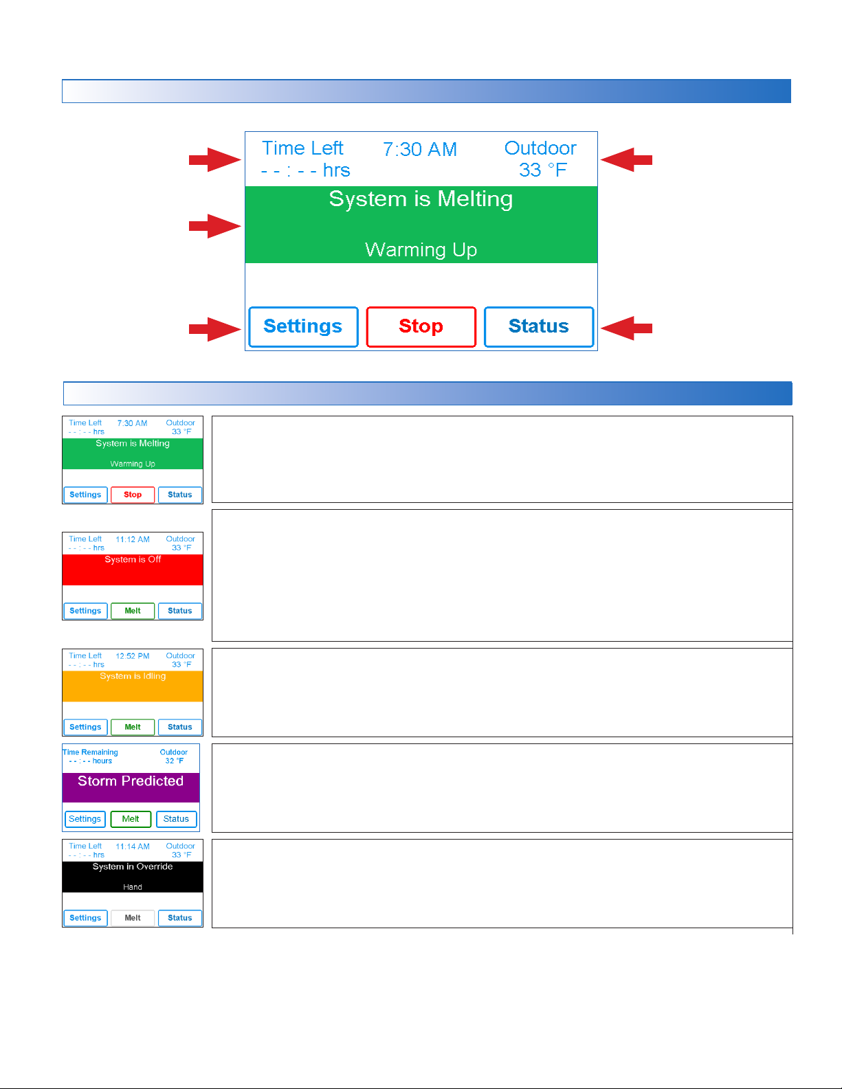
Home Screen
Remaining melting
run time
System operation
information
Go to settings menu
to setup control
System Operation
Information about slab
and outdoor conditions
View status of sensor
readings and equipment.
SYSTEM IS MELTING
•
The control has either detected snow/ice and automatically started or the control was manually
started.
• "Warming Up" is shown when the slab is below the slab target temperature.
SYSTEM IS OFF
• The snow melting system is off and is ready to detect snow or ice.
•
"Warm Weather Shut Down" is shown when the slab and outdoor temperature are above the
WWSD setting. During WWSD, the snow will melt naturally due to warm outdoor temperatures.
• "Cold Weather Shut Down" is shown when the outdoor temperature is below the CWCO setpoint.
The outdoor temperature is so cold the heating system does not have capacity to melt snow.
•
"Melt Pending" is shown when the system is off during CWCO but will resume melting once the
outdoor temperature increases above the CWCO setpoint.
SYSTEM IS IDLING
• The control is pre-heating the slab to the idling setpoint. This reduces the amount of time needed
to reach the melting setpoint in the event snow or ice is detected.
STORM PREDICTED
•
The Internet weather forecast is predicting a snow fall and the control is pre-heating the slab to
the storm setpoint. This reduces the amount of time needed to reach the melting setpoint in the
event snow or ice is detected.
SYSTEM IN OVERRIDE / SYSTEM IN EXERCISING
• The control is in a manual override for testing, commissioning or exercising.
• The description field explains which type of override is active.
15 of 48
© 2016 tekmar 670_D - 10/16
Page 16
Symbols
!
WARNING SYMBOL
The control has a error message. Press the warning symbol to determine the error code and information on how
to take corrective action. Refer to the Troubleshooting section for a list of error codes.
Help Screen
The display includes a Help screen for each setting. The Help screen provides a description of the setting that is identical to
the description found in the Installation and Operation Manual.
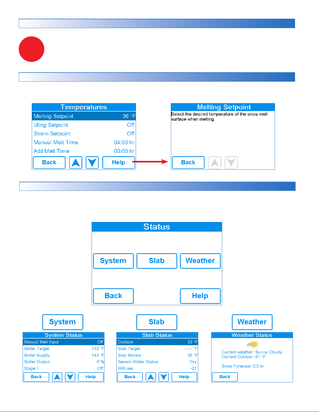
Status Menu Navigation
Step 1: Press the Status button on the Home Screen.
Step 2: Press either the System, Slab or Weather button.
Step 3: Press up or down buttons to scroll through the list.
© 2016 tekmar 670_D - 10/16
16 of 48
Page 17

System Status Menu
Description Range Access
MANUAL MELT INPUT
When Manual Melt wiring terminal 13 is shorted to common wiring terminal 14, the control is enabled
and enters the melting operation unless prevented by warm weather shut down or cold weather
cut out. When the manual melt input is disconnected, the control completes the melting cycle and
then returns to off, idle or storm operation.
Conditions: Always
TEKMARNET
When tekmarNet communication is present, the status shows active. When there is no tekmarNet
communication, the status is off.
Conditions: Always
Off, Enabled
Off, Active
User
Installer
User
Installer
BOILER TARGET
The boiler target calculated by the control based on outdoor temperature, slab temperature and the
melting, idling, or storm setpoints. “- - -” is displayed when no heat is required.
Conditions: Application mode is set to Boiler or Boiler+Mix.
BOILER SUPPLY
Current boiler supply water temperature.
Conditions: Application mode is set to Boiler or Boiler+Mix.
BOILER OUTPUT
Current boiler plant percent output.
Conditions: Application mode is set to Boiler or Boiler+Mix.
STAGE 1
Current status of the stage 1 relay.
Conditions: Application mode is set to PWM Zone, Mixing, Boiler, or Boiler+Mix.
STAGE 2
Current status of the stage 2 relay.
Conditions:
MIX TARGET
The mix target calculated by the control based on outdoor temperature, slab temperature
and one of either the melting, idling, or storm setpoints. ”- - -” is displayed when no heat is
required.
Conditions: Application mode is set to Mixing or Boiler+Mix.
MIX SUPPLY
Current mix supply water temperature.
Conditions: Application mode is not set to Electric.
Boiler type is set to Stage 2.
– – –,
50 to 230°F
(10.0 to 110.0°C)
-31 to 266°F
(-35.0 to 130.0°C)
0 to 100%
On or Off
On or Off
– – –,
70 to 200°F
(21.0 to 93.5°C)
-31 to 266°F
(-35.0 to 130.0°C)
User
Installer
Installer
User
Installer
User
Installer
User
Installer
User
Installer
User
Installer
MIX OUTPUT
Current position of the mixing valve or output of the variable speed injection pump.
Conditions: Application mode is set to Mixing or Boiler+Mix.
SYSTEM PUMP
Current status of the system loop pump.
Conditions: Application mode is set to PWM Zone, Mixing or Boiler+Mix.
HEAT RELAY
Current status of the heat relay.
Conditions: Application mode is set to PWM Zone, Boiler, Mixing or Boiler+Mix.
ELECTRIC ENABLE RELAY
Current status of the electric snow melt enable relay.
Conditions: Application mode is set to Electric.
17 of 48
0 to 100%
On or Off
On or Off
On or Off
© 2016 tekmar 670_D - 10/16
User
Installer
User
Installer
User
Installer
User
Installer
Page 18
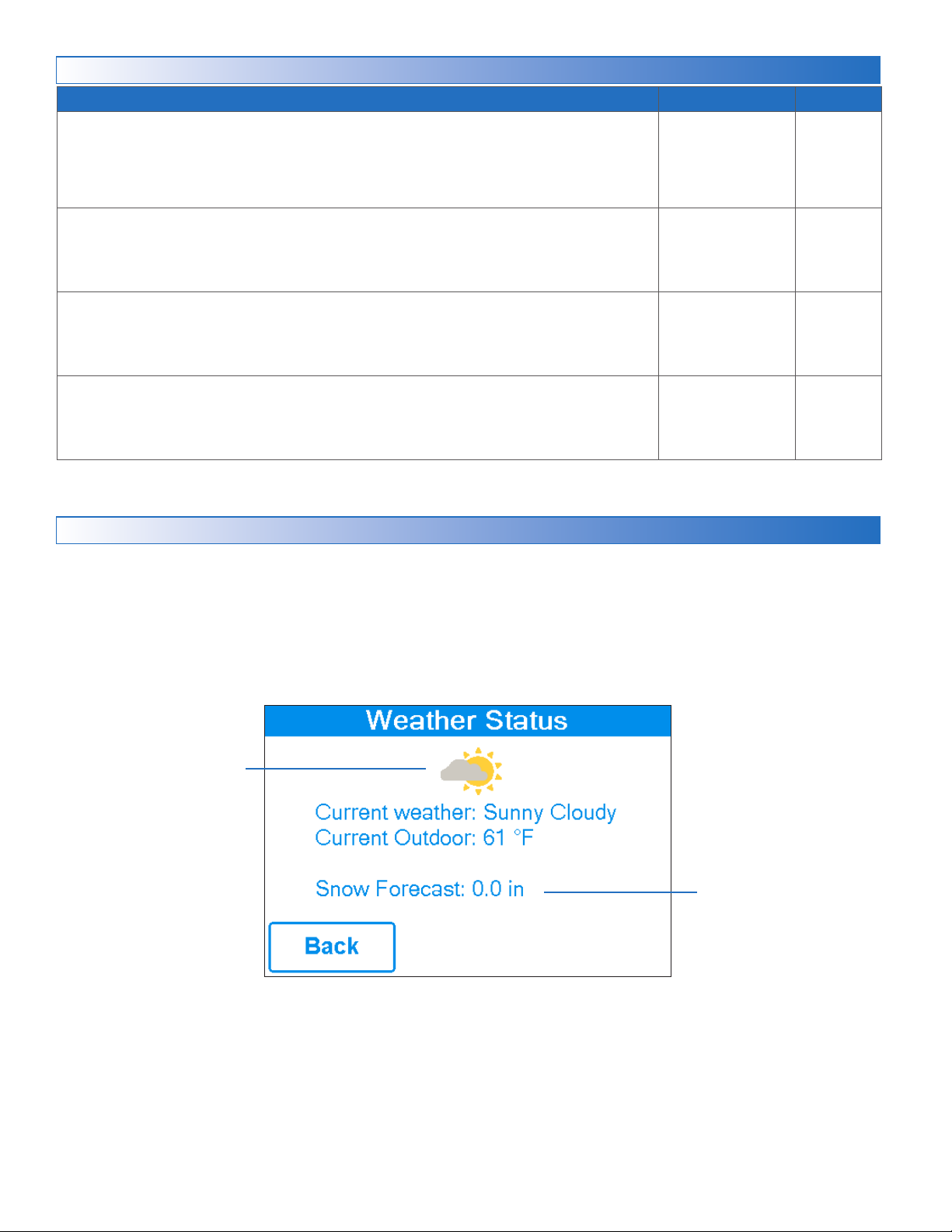
Slab Status Screen
Description Range Access
OUTDOOR
Current outdoor air temperature as measured by the outdoor sensor or from the tekmarNet
system or Internet weather forecast. “– – –” is displayed when no outdoor temperature reading
is available.
Conditions: Always available.
SLAB TARGET
The slab target calculated by the control based on outdoor temperature and the melting,
idling, or storm setpoints. “- - -” is displayed when no heat is required.
Conditions: Always available.
SLAB SENSOR
Current slab sensor temperature.
Conditions:
SENSOR WATER STATUS
Current status of snow/ice sensor moisture detector.
Conditions:
Snow/ice sensor set to In-slab or slab sensor is set to On.
Snow/ice sensor is set to In-slab or Aerial.
– – –,
-67 to 149°F
(-55.0 to 65.0°C)
– – –,
32 to 110°F
(0 to 43.0°C)
-58 to 167°F
(-50.0 to 75.0°C)
DRY or WET
User
Installer
Installer
User
Installer
User
Installer
Weather Status Screen
When WiFi is turned on, the control receives weather data from the Internet. The current weather, outdoor temperature and
forecast snow fall information is displayed.
Current outdoor conditions
© 2016 tekmar 670_D - 10/16
Predicted snow forecast
18 of 48
Page 19
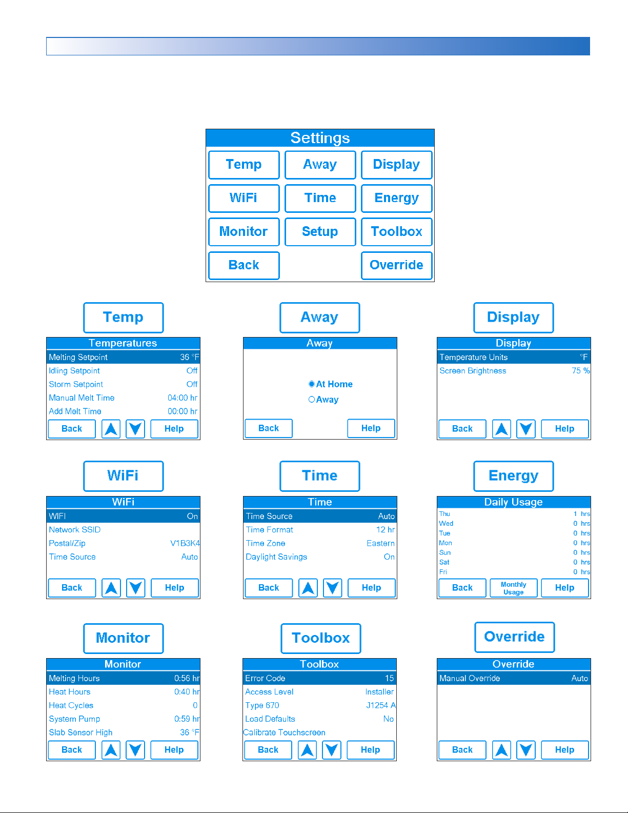
Settings Menu Navigation
Step 1: Press the Settings button on the Home Screen.
Step 2: Press one of the ten buttons.
Step 3: Press up or down buttons to scroll through the list.
Step 4: Press the highlighted setting name to change the setting value.
®
•
19 of 48
© 2016 tekmar 670_D - 10/16
Page 20

Temp Menu
Description Range Access
MELTING SETPOINT
Select the desired temperature of the snow melt surface when melting.
Conditions: Always available.
IDLING SETPOINT
Select the desired temperature of the snow melt surface when idling. Idling preheats the slab
when the slab is dry but cold and allows faster reaction time to reach the melting temperature
when snow is detected. Recommended for commercial use only.
Conditions: Always available.
STORM SETPOINT
Select the desired temperature of the snow melt surface while operating in the storm
operation. Storm operation temporarily preheats the slab to allow faster reaction time to
reach the melting temperature when snow is detected. Storm operation is automatically
activated by the Internet weather forecast or manually started by a User Switch or Gateway.
Conditions: Always available.
MANUAL MELT TIME
Select the amount of running time when manually starting the system.
Conditions: Always available.
ADD MELT TIME
Select the amount of additional melting time after the Snow/Ice Sensor is dry. This allows
low spots on the slab to fully dry before the snow melting system is shut off.
Conditions: Snow/ice sensor is set to In-slab or Aerial
32 to 95°F
(0.0 to 35.0°C)
Default = 36°F
(2.0°C)
OFF, 20 to 95°F
(-6.5 to 35.0°C)
Default = Off
OFF, 20 to 95°F
(-6.5 to 35.0°C)
Default = Off
0:30 to 24:00
hours
Default = 4:00
hours
0:00 to 6:00
hours
Default = 0:00
hours
User
Installer
User
Installer
User
Installer
User
Installer
Installer
STORM RUN TIME
Select the amount of storm run time to pre-heat the slab when advised of a winter storm
warning.
Conditions:
SENSITIVITY
Select how sensitive Snow/Ice Sensor is to water detection.
Conditions: Snow/ice sensor is set to In-slab or Aerial.
WWSD
Select the temperature above which the snow melting system is shut off during warm
weather. This allows the snow or ice to melt off the slab naturally.
Conditions: Always available.
CWCO
Select the temperature below which the snow melting system is shut off during extremely
cold weather. Below this temperature, the heat loss of the slab exceeds the capacity of the
boiler or heating appliance.
Conditions: Always available.
Storm setpoint is set to a temperature.
0:30 to 24:00
hours
Default = 8:00
hours
Auto, Min, -2, -1,
Mid, +1, +2, Max
Default = Auto
Auto, 32 to 95°F
(0.0 to 35.0°C)
Default = Auto
Off, -30 to 50°F
(-34.5 to 10.0°C)
Default = 10°F
(-12.0°C)
Installer
Installer
Installer
Installer
© 2016 tekmar 670_D - 10/16
20 of 48
Page 21
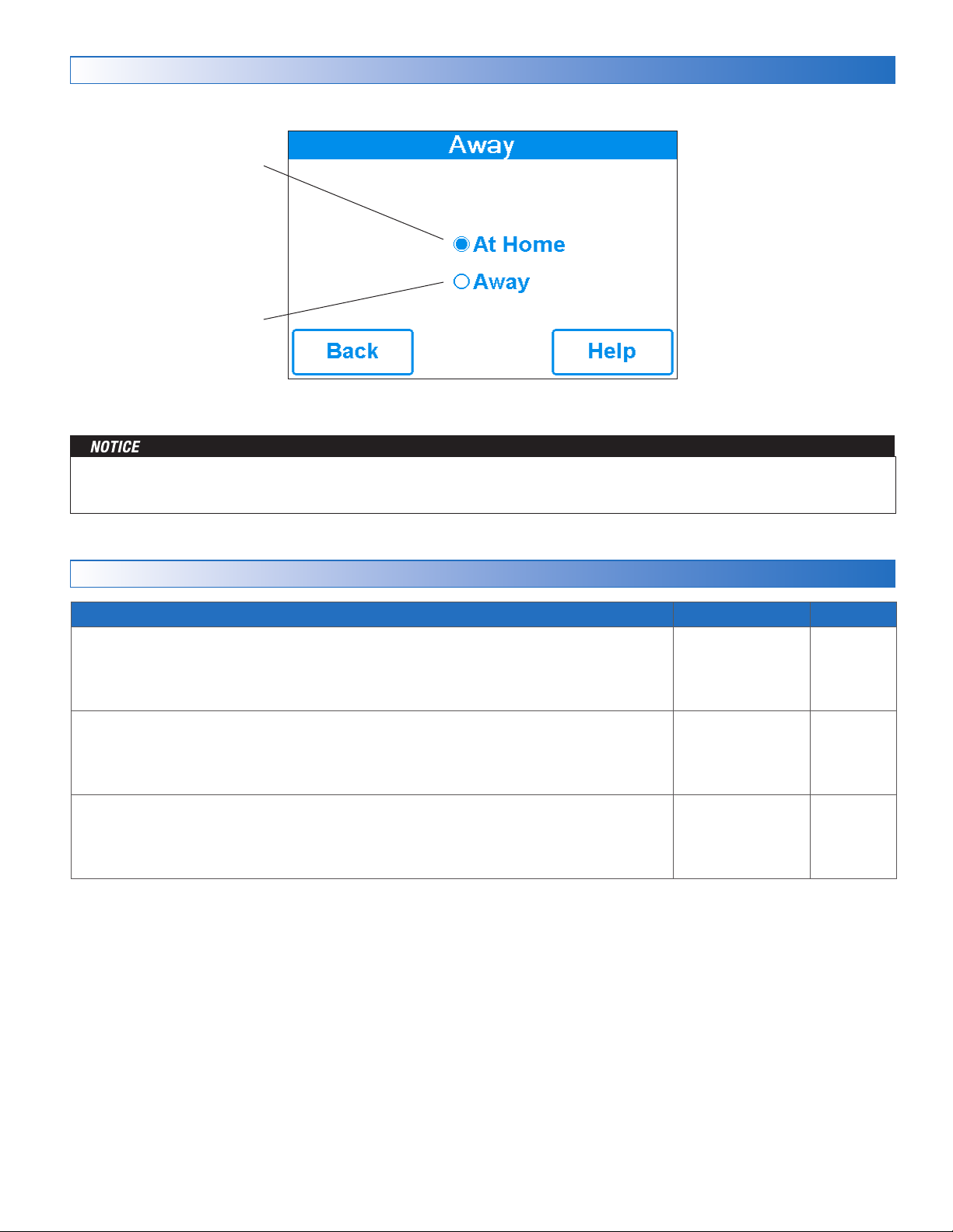
Away Menu
At Home
Select at home to allow automatic snow melting operation.
Away
Select away to prevent snow
melting operation and save
energy.
The home/away changes devices system-wide. All thermostats and controls that are grouped together as a location on the
tekmar Connect mobile app will change together. All thermostats and controls on a tekmarNet system will also change together.
Display Menu
Description Range Access
TEMPERATURE UNITS
Select Fahrenheit or Celsius temperature units.
Conditions: Always available.
SCREEN BRIGHTNESS
Select the screen brightness.
Conditions: Always available.
CLEAN SCREEN
The Clean Screen timer locks the screen for 10 seconds allowing the user to wipe the screen
with a moist cloth. Do not use solvents to clean the screen.
Conditions: Always available.
°F or°C
0 to 100%
Default = 75%
N/A
User
Installer
User
Installer
User
Installer
21 of 48
© 2016 tekmar 670_D - 10/16
Page 22
WiFi Menu
Before using the WiFi features of this product, you must accept the Terms of Use, as amended from time to time and available at
WattsWater.com/Terms-of-Use. If you do not accept these terms, this product can still be used without WiFi features.
Description Range Access
WIFI
Enable or disable WiFi connectivity. The help screen displays the following information:
• IP Address
• Subnet Mask
• Gateway IP
• MAC Address
Conditions: Always available.
Off or On
User
Installer
NETWORK SSID
Select the WiFi network from the list.
Conditions: WiFi is set to On.
ZIP/POSTAL CODE
Enter a US ZIP or Canadian postal code. The ZIP/Postal Code is used to provide the location
for the weather information. The weather service is available in the USA and Canada only.
Conditions: WiFi is set to On.
TIME SOURCE
Select to set to the time automatically or manually.
Conditions: WiFi is set to On.
Time Menu
Description Range Access
TIME SOURCE
Select to set to the time automatically or manually. Auto is only available when WiFi is set to On.
Conditions: Always available.
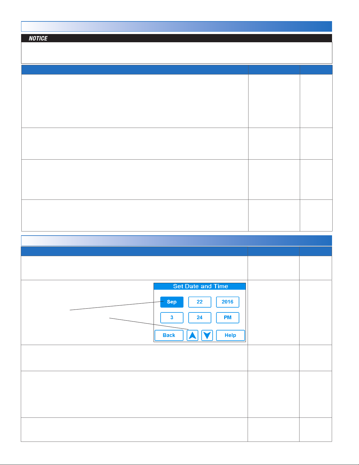
SET TIME AND DATE
Conditions: Always available.
List of WiFi
Networks
US ZIP format
12345
Canada Postal
Code format
A1B2C3
Auto,
Manual
Auto,
Manual
User
Installer
User
Installer
User
Installer
User
Installer
• Press box field.
• Then adjust with arrow buttons.
TIME FORMAT
Select either 12 or 24 hour format.
Conditions: Always available.
TIME ZONE
Select the location's time zone.
Conditions: Available when Time Source is set to Manual.
DAYLIGHT SAVINGS
Set Daylight Savings to On to automatically adjust for time changes in the spring and fall.
Conditions: Always available.
© 2016 tekmar 670_D - 10/16
22 of 48
N/A
12 hr,
24 hr
Default = 12 hr
Hawaii, Alaska,
Pacific, Mountain,
Central, Eastern,
Atlantic,
NFLD,
(Newfoundland)
Off or On
Default = On
User
Installer
User
Installer
User
Installer
User
Installer
Page 23
Energy Menu
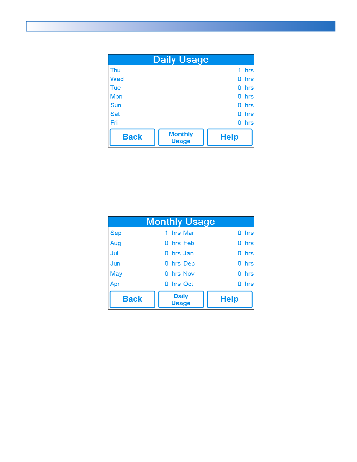
View the snow melting system running hours in the past week.
View the snow melting system running hours in the past year.
23 of 48
© 2016 tekmar 670_D - 10/16
Page 24

Monitor Menu
Description Range Access
MELTING ENERGY
Records the amount of energy since the counter was last reset.
Conditions: Available when Application Mode is set to Electric.
MELTING HOURS
Records the number of melting hours since the counter was last reset.
Conditions: Always available.
HEAT HOURS
Records the number of hours the boiler fired or the electric cable heated since the counter
was last reset.
Conditions: Available when Application Mode is Boiler, Boiler+Mix and Electric.
HEAT CYCLES
Records the number of cycles the boiler turned on or the electric cable heated since the
counter was last reset.
Conditions: Available when Application Mode is Boiler, Boiler+Mix and Electric.
SYSTEM PUMP
Records the number of hours the system pump has operated since the counter was last
reset.
Conditions: Available when Application Mode is not set to Electric.
SLAB SENSOR HIGH
Records the highest measured slab temperature since the counter was last reset.
Conditions: Available when Snow/Ice Sensor is set to In-slab or Slab Sensor = On.
SLAB SENSOR LOW
Records the lowest measured slab temperature since the counter was last reset.
Conditions: Available when Snow/Ice Sensor is set to In-slab or Slab Sensor = On.
0 to 999999 kWh
0 to 999999
hours
0 to 999999
hours
0 to 999999
cycles
0 to 999999
hours
-58 to 167°F
(-50.0 to 75.0°C)
-58 to 167°F
(-50.0 to 75.0°C)
User
Installer
User
Installer
User
Installer
Installer
Installer
Installer
Installer
OUTDOOR HIGH
Records the highest measured outdoor air temperature since the counter was last reset.
Conditions: Always available.
OUTDOOR LOW
Records the lowest measured outdoor air temperature since the counter was last reset.
Conditions: Always available.
BOILER HIGH
Records the highest measured boiler temperature since the counter was last reset.
Conditions: Available when Application Mode is set to Boiler or Boiler+Mix.
BOILER LOW
Records the lowest measured boiler temperature since the counter was last reset.
Conditions: Available when Application Mode is set to Boiler or Boiler+Mix.
MIX SUPPLY HIGH
Records the highest measured mix temperature since the counter was last reset.
Conditions: Available when Application Mode is set to PWM Zone, Mixing or Boiler+Mix.
MIX SUPPLY LOW
Records the lowest measured mix temperature since the counter was last reset.
Conditions: Available when Application Mode is set to PWM Zone, Mixing or Boiler+Mix.
RESET ALL?
Resets all the counters in the monitor menu at once.
Conditions: Always available.
-67 to 149°F
(-55.0 to 65.0°C)
-67 to 149°F
(-55.0 to 65.0°C)
-31 to 266°F
(-35.0 to 130.0°C)
-31 to 266°F
(-35.0 to 130.0°C)
-31 to 266°F
(-35.0 to 130.0°C)
-31 to 266°F
(-35.0 to 130.0°C)
N/A
Installer
Installer
Installer
Installer
Installer
Installer
Installer
© 2016 tekmar 670_D - 10/16
24 of 48
Page 25
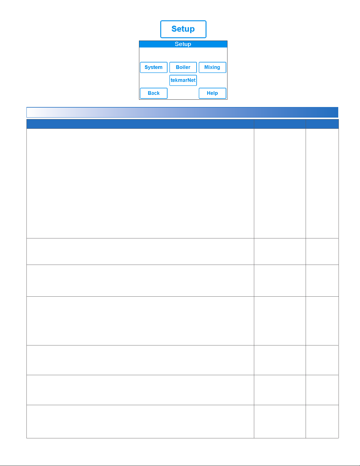
Setup – System Setup Menu
Description Range Access
APPLICATION MODE
The Application Mode selects the operation of the mechanical equipment.
Application Mode “PWM Zone” operates a pump or zone valve to provide heat to the snow melting
system.
Application Mode “Mixing” operates a mixing valve or a variable speed injection mixing pump to
heat the snow melting system. The heat source is enabled.
Application Mode “Boiler” operates a modulating, 1-stage or 2-stage boiler to heat the snow melting
system.
PWM Zone
Mixing
Boiler
Boiler+Mix
Electric
Installer
Application Mode “Boiler+Mix" operates a mixing valve or a variable speed injection mixing pump
and controls the boiler temperature to heat the snow melting system.
Application Mode “Electric” uses electric cables to heat the snow melting system.
Conditions: Always available.
SNOW/ICE SENSOR
Select if a Snow/Ice Sensor 090 or 094 "Inslab", or a Snow Sensor 095 "Aerial" is installed.
Conditions: Always available.
SLAB SENSOR
Select if a Slab Sensor 072 or 073 is installed.
Conditions: Available when snow/ice sensor is set to None or Aerial.
SLAB PROTECTION
Select if a concrete slab should be protected from large temperature differentials to avoid
cracking the concrete due to high tensile stress. This limits the heat-up rate of the concrete
slab. Slab protection is not required for installations with brick pavers, asphalt or other
non-concrete materials.
Conditions: Available when 1) Application mode is set to Mixing, Boiler or Boiler+Mix, 2)
Snow/ice sensor is set to Inslab or slab sensor is set to On.
ECONOM ELT
EconoMelt allows the user to mechanically remove snow then manually start the system
to melt the remaining thin snow layer or ice with an automatic stop when the sensor is dry.
Conditions: Available when snow/ice sensor is set to In-slab.
Default =
Boiler+Mix
None,
In-slab, Aerial
Default = In-slab
Off or On
Default = Off
Off or On
Default = On
Off or On
Default = Off
Installer
Installer
Installer
Installer
MAX MELT DAYS
Limit the amount of melting run time after snow is automatically detected by a Snow/Ice
Sensor 090 or 094, or a Snow Sensor 095.
Conditions: Always available.
OUTDOOR SENSOR
Select if the outdoor air temperature is measured by the control, by a tekmarNet system or
by the Internet weather service.
Conditions: Always available.
25 of 48
Off, 0.5 to 7 days
Default = 3 days
Control,
tekmarNet,
Internet
Default = Control
© 2016 tekmar 670_D - 10/16
Installer
Installer
Page 26

Setup – Boiler Setup Menu
Description Range Access
BOILER TYPE
Select the type of boiler operated by the control.
Mod = Modulating boiler with an adjustable firing rate using a 0-10V (dc) or 4-20 mA signal.
1 Stage = Single one-stage on/off boiler.
2 Stage = Single two-stage on/off boiler.
EMS = Modulating boiler with an adjustable target temperature using a 0-10V (dc) or 4-20 mA signal.
Enable = Enable for Application Mode PWM Zone or Mix.
Control = Call for heat to tekmarNet control.
Conditions: Always available.
Mod,
1 Stage,
2 Stage,
EMS,
Enable,
Control
Default = Mod
Installer
BOILER MODULATION TYPE
Select between a 0-10 V (dc) or 4-20 mA signal to control the modulating boiler.
Conditions: Available when 1) Application Mode is set to Boiler or Boiler+Mix, and 2) Boiler Type
is set to Mod or EMS.
BOILER MIN MODULATION
Set the boiler minimum modulation of the boiler burner.
Conditions: Available when 1) Application Mode is set to Boiler or Boiler+Mix, and 2) Boiler Type
is set to Mod.
BOILER MODULATION DELAY
Set the time the boiler operates at the minimum firing rate before allowing the firing rate to
change. This allows the boiler ignition system to establish a flame.
Conditions: Available when 1) Application Mode is set to Boiler or Boiler+Mix, and 2) Boiler Type
is set to Mod.
BOILER MOTOR SPEED
Set the time required for the modulating burner actuating motor to fully open the gas valve
or ramp the burner fan speed from off to full speed. Set to 30 seconds unless otherwise
recommended by the boiler manufacturer.
Conditions: Available when 1) Application Mode is set to Boiler or Boiler+Mix, and 2) Boiler Type
is set to Mod.
BOILER DIFFERENTIAL
The temperature differential that the control uses to cycle the boiler on and off. The differential
is split evenly half above and half below of the boiler target.
Conditions: Available when Application Mode is set to Boiler or Boiler+Mix.
0-10 V
or
4-20 mA
Default: 0-10 V
0 to 50%
Default = 0%
Off, 10 to 180
seconds
Default = Off
30 to 230
seconds
Default = 30
Auto, 2 to 42°F
(1.0 to 23.5°C)
Default = Auto
Installer
Installer
Installer
Installer
Installer
BOILER MINIMUM
When Application Mode is set to Mixing or Boiler+Mix:
The boiler return minimum protects both condensing and non-condensing boilers from cold
return water temperatures. The mixing valve is closed or the variable speed injection mixing
is reduced when the boiler return temperature falls below this setting.
When Application Mode is set to Boiler:
The minimum allowed boiler target temperature. Check the boiler manufacturer’s manual
for recommended return water temperatures.
EMS SIGNAL MINIMUM
The starting voltage for the EMS boiler signal. This voltage corresponds to the EMS Low
Temperature setting. Check the boiler manufacturer’s manual for the starting voltage for
the EMS signal range.
Conditions: Available when 1) Boiler Type is set to EMS, and 2) Boiler Modulation Type is
set to 0-10 V.
EMS LOW TEMPERATURE
The EMS boiler target temperature that corresponds to the EMS Signal Minimum voltage
or 4 mA. Check the boiler manufacturer’s manual for the minimum EMS target temperature.
Conditions: Available when Boiler Type is set to EMS.
EMS HIGH TEMPERATURE
The EMS boiler target temperature that corresponds to 10 V (dc) or 20 mA. Check the boiler
manufacturer’s manual for the maximum EMS target temperature.
Conditions: Available when Boiler Type is set to EMS.
© 2016 tekmar 670_D - 10/16
26 of 48
Off, 50 to 180°F
(10.0 to 82.0°C)
Default = Off
0.5 to 10 Vdc
Default = 0.5 Vdc
50 to 210°F
(10 to 99.0°C)
Default = 50°F
(10.0°C)
50 to 210°F
(10.0 to 99.0°C)
Default = 210°F
(99.0°C)
Installer
Installer
Installer
Installer
Page 27

Setup – Mixing Setup Menu
Description Range Access
MIXING TYPE
Select the mixing output type.
Floating = Floating action mixing output to operate a mixing valve.
Injection = Injection mixing output to operate a wet-rotor, impedance protected pump with a current
less than 2.4 A.
0-10 V = Analog mixing output provides a 0-10 V (dc) signal.
4-20 mA = Analog mixing output provides a 4-20 mA signal.
Conditions: Available when Application Mode is set to Mixing or Boiler+Mix.
Floating,
Injection,
0-10 V,
4-20 mA
Default = Floating
Installer
MIX MOTOR SPEED
Set the time that the mixing actuating motor requires to operate from fully closed to fully open.
Check the mixing actuator motor instruction manual for the motor speed time.
Conditions: Available when 1) Application Mode is set to Mixing or Boiler+Mix, and 2) Mixing Type
is set to Floating, 0-10 V, or 4-20 mA.
MIX MAXIMUM
Set the maximum operating temperature of the system supply water temperature.
Conditions: Available when Application Mode is set to Mixing or Boiler+Mix.
30 to 230
seconds
Default = 105
seconds
80 to 180°F, Off
(26.5 to 82.5°C)
Default = 140°F
(60.0°C)
Installer
Installer
27 of 48
© 2016 tekmar 670_D - 10/16
Page 28

tekmarNet Menu
Description Range Access
ADDRESSING
The tekmarNet address of this control. Select between automatic and manual addressing.
To manually set the address, use the up or down buttons.
Conditions: Available when the 670 is connected to other controls using tekmarNet communication.
DEVICE COUNT
Provides a count of all the tekmarNet thermostats, setpoint controls and snow melting controls
on a tN4 bus.
Conditions: Available when the 670 is connected to other controls using tekmarNet communication.
SNOW MELT ZONE
Select the snow melting zone that this control operates. Snow zone 1 has the highest priority
while snow zone 12 has the lowest priority.
Conditions: Available when the 670 is connected to other controls using tekmarNet communication.
TRACK ZONE
Select to track and record the running hours of snow zone 1 and repeat this run time on this
control. This allows snow melting zones without a snow/ice sensor to automatically start.
Conditions: Available when 1) The 670 is connected to other controls using tekmarNet communication
and 2) Snow zone is set to 2 through 12.
MELT GROUP
A User Switch or Gateway may be used to manually start melting the zone. Set the Melt
Group number to the corresponding Setpoint Enable number on the User Switch or Gateway.
Conditions: Available when the 670 is connected to other controls using tekmarNet communication.
STORM GROUP
A User Switch or Gateway may be used to manually start the storm operation for the zone.
Set the Storm Group number to the corresponding Setpoint Enable number on the User
Switch or Gateway.
Conditions: Available when the 670 is connected to other controls using tekmarNet communication.
Auto,
b:01 to b:24,
1:01 to 1:24,
2:01 to 2:24,
3:01 to 3:24
1 to 24
1 to 12
Off or On
1 to 12
1 to 12
Installer
Installer
Installer
Installer
Installer
Installer
PRIORITY
Select the priority of the snow melting system.
Conditions: Available when 1) The 670 is connected to other controls using tekmarNet communication
and 2) Application Mode is set to PWM Mode, Mix or Electric.
AWAY SCENE
Select if the control should accept or ignore the away command from the mobile app or
from a tekmarNet system.
Conditions: Always available.
TN4 SYSTEM PUMP
Select if the system pump located on the tekmarNet System Control should operate when
the snow melt zone is heating.
Conditions: Available when the 670 is connected to other controls using tekmarNet communication.
Off, Conditional,
Full
Default = Off
Off or On
Default = On
Off or On
Installer
Installer
Installer
© 2016 tekmar 670_D - 10/16
28 of 48
Page 29

Toolbox Menu
Description Range Access
ERROR CODE
The current error code is displayed.
Conditions: Always available.
ACCESS LEVEL
Select the access level of the control. This determines which menus and items are available
through the user interface.
Conditions: Always available.`
TYPE 670
Product information.
SW: J1254A
SVN: XXX
Conditions:
LOAD DEFAULTS
Select “Yes” to reload the factory defaults on the control.
Conditions: Always available.
CALIBRATE TOUCHSCREEN
A sequence of steps to calibrate the touchscreen.
Conditions: Always available.
Always available.
See Error Code
Section
User or Installer
Default = Installer
J1254A
Last letter indicates
software version
No or Yes
N/A
User
Installer
User
Installer
User
Installer
User
Installer
User
Installer
29 of 48
© 2016 tekmar 670_D - 10/16
Page 30

Override Menu
Description Range Access
MANUAL OVERRIDE
Manually override the normal automatic operation of the control to test the equipment or operate
the system at the maximum temperature limits.
Auto = Normal operation.
Hand = Manual override of each relay output.
Max Heat = Operate hydronic system at maximum heat.
Test = Operate electric system for 10 minutes.
Purge = Hydronic system purge operates pumps to help bleed air from the system.
Conditions: Always available.
Auto,
Hand,
Max Heat,
Test,
Purge,
Off
User
Installer
SYSTEM PUMP
Manually turn on the system pump during the HAND Manual Override.
Conditions: Available when 1) Application Mode is set to PWM Zone, Boiler, Mixing or Boiler+Mix,
and 2) Manual Override is set to Hand.
HEAT RELAY
Manually turn on the heat relay during the HAND Manual Override.
Conditions: Available when 1) Application Mode is set to PWM Zone, Mix or Electric and 2) Manual
Override is set to Hand.
BOILER ENABLE
Manually turn on the boiler during the HAND Manual Override.
Conditions: Available when 1) Application Mode is set to PWM Zone or Mix and 2) Manual Override
is set to Hand.
BOILER MODULATION
Manually set the modulating boiler firing rate during the HAND Manual Override.
Conditions: Available when 1) Application Mode is set to Boiler or Boiler+Mix, 2) Manual Override
is set to Hand, and 3) Boiler Type is set to Mod.
BOILER STAGE 1
Manually turn on the boiler stage 1 during the HAND Manual Override.
Conditions: Available when 1) Application Mode is set to Boiler, Boiler+Mix and 2) Manual Override
is set to Hand.
BOILER STAGE 2
Manually turn on the boiler stage 2 during the HAND Manual Override.
Conditions: Available when 1) Application Mode is set to Boiler or Boiler+Mix, 2) Manual Override
is set to Hand, and 3) Boiler Type is set to Stage 2.
Off or On
Default = Off
Off or On
Off or On
Default = Off
0 to 100%
Default = 0%
Off or On
Default = Off
Off or On
Default = Off
User
Installer
User
Installer
User
Installer
User
Installer
User
Installer
User
Installer
BOILER EMS
Manually set the modulating boiler firing rate during the HAND Manual Override.
Conditions: Available when 1) Application Mode is set to Boiler or Boiler+Mix, 2) Manual Override
is set to Hand, and 3) Boiler Type is set to EMS.
MIX OUTPUT
Manually set the mixing valve or injection mixing pump output during the HAND Manual Override.
Conditions: Available when 1) Application Mode is set to Mixing or Boiler+Mix, and 2) Manual
Override is set to Hand.
HAND DURATION
Select the amount of time that the HAND Override is in effect before returning to Automatic operation.
Conditions: Available when Manual Override is set to Hand.
MAX HEAT DURATION
Select the amount of time that Max Heat is in effect before returning to Automatic operation.
Conditions: Available when 1) Application Mode is set to PWM Zone, Boiler, Mixing or Boiler+Mix,
and 2) Manual Override is set to Max Heat.
PURGE DURATION
Select the amount of time that the Purge is in effect before returning to Automatic operation.
Conditions: Available when 1) Application Mode is set to PWM Zone, Boiler, Mixing or Boiler+Mix,
and 2) Manual Override is set to Purge.
© 2016 tekmar 670_D - 10/16
30 of 48
Off, 50 to 210°F
(10 to 99.0°C)
Default = Off
0 to 100%
Default = 0%
0:10 to 72:00
hours
Default = 0:10 hour
0:10 to 72:00
hours
Default = 24:00 hour
0:10 to 72:00
hours
Default = 24:00 hour
User
Installer
User
Installer
User
Installer
User
Installer
User
Installer
Page 31
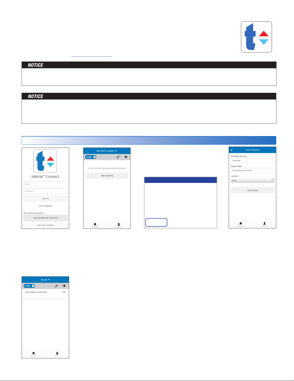
tekmar Connect Mobile & Web App
The WiFi Snow Melting Control can be remotely viewed and adjusted
remotely from the tekmar Connect app.
•
Download the tekmar Connect mobile app from the iTunes® App Store®
or from the Google PlayTM Store.
• Alternatively go to the tekmarConnect.com website.
Before using the WiFi features of this product, you must accept the Terms of Use, as amended from time to time and available
at WattsWater.com/Terms-of-Use. If you do not accept these terms, this product can still be used without WiFi features.
The control uses the following outbound ports to connect to the Internet:
HTTP port 80, SNTP port 123, TLS port 443, MQTT port 883
Networks blocking outbound ports will need to allow open these ports based upon the control's MAC address.
Add Control to App
Step 1
• Create a new account.
• Then login using
your user name and
password.
Step 2
Click Add a Device
The 670 is now
listed on the My
Devices page.
REGISTRATION
To finish registering your sn ow melt control, enter
the code displayed below at tekmarConnect.com
8718 0139
Back
Step 3
On the 670, press:
• Settings
• WiFi
• Register Device
Step 4
• Enter the 8 digit
registration number
from the 670.
• Enter the device's
name.
• The app supports
multiple site locations.
Enter the location for
the 670.
31 of 48
© 2016 tekmar 670_D - 10/16
Page 32
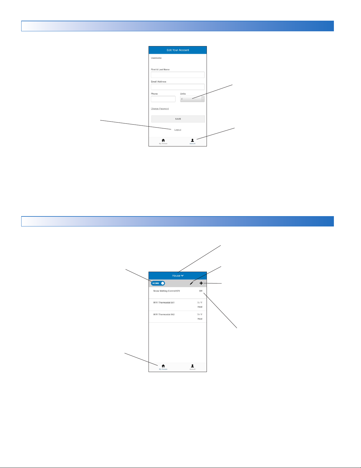
Account
Edit your account details:
• First and last name
• Email address
• Phone number
Logout of the app
your name@d omain.com
Your Name
555-555-5555
Change the temperature units.
Account
Takes you to the account page.
My Devices
Home/Away
•
Toggles a location between
home and away.
•
Selecting away saves energy
by permanently shutting off
the snow melt system.
•
Thermostats operate at
energy saving temperatures.
My Devices
Lists all the devices at a location
Locations
Change to different locations.
Add More Locations
Add More Devices
Device Name
Takes you to the adjustment
page for the device.
© 2016 tekmar 670_D - 10/16
32 of 48
Page 33
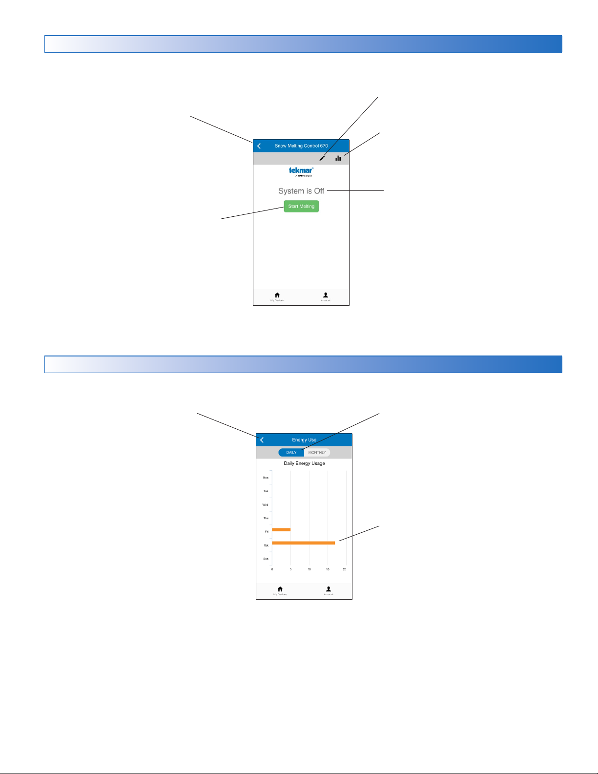
Control Operation
Back to My Devices
• Press to start melting
• Press to stop melting
• Greyed out when off for Warm
Weather Shut Down
or Cold Weather Cut Out
• Edit device name
• Delete devices
View run time energy usage
Provides control status:
• System is Off
• System is Melting
• Storm Predicted
• System is Idling
• System in Override
Energy Usage
Back to control page
Toggle between daily and monthly energy
usage views.
Number of hours the snow melting system
is operating.
33 of 48
© 2016 tekmar 670_D - 10/16
Page 34
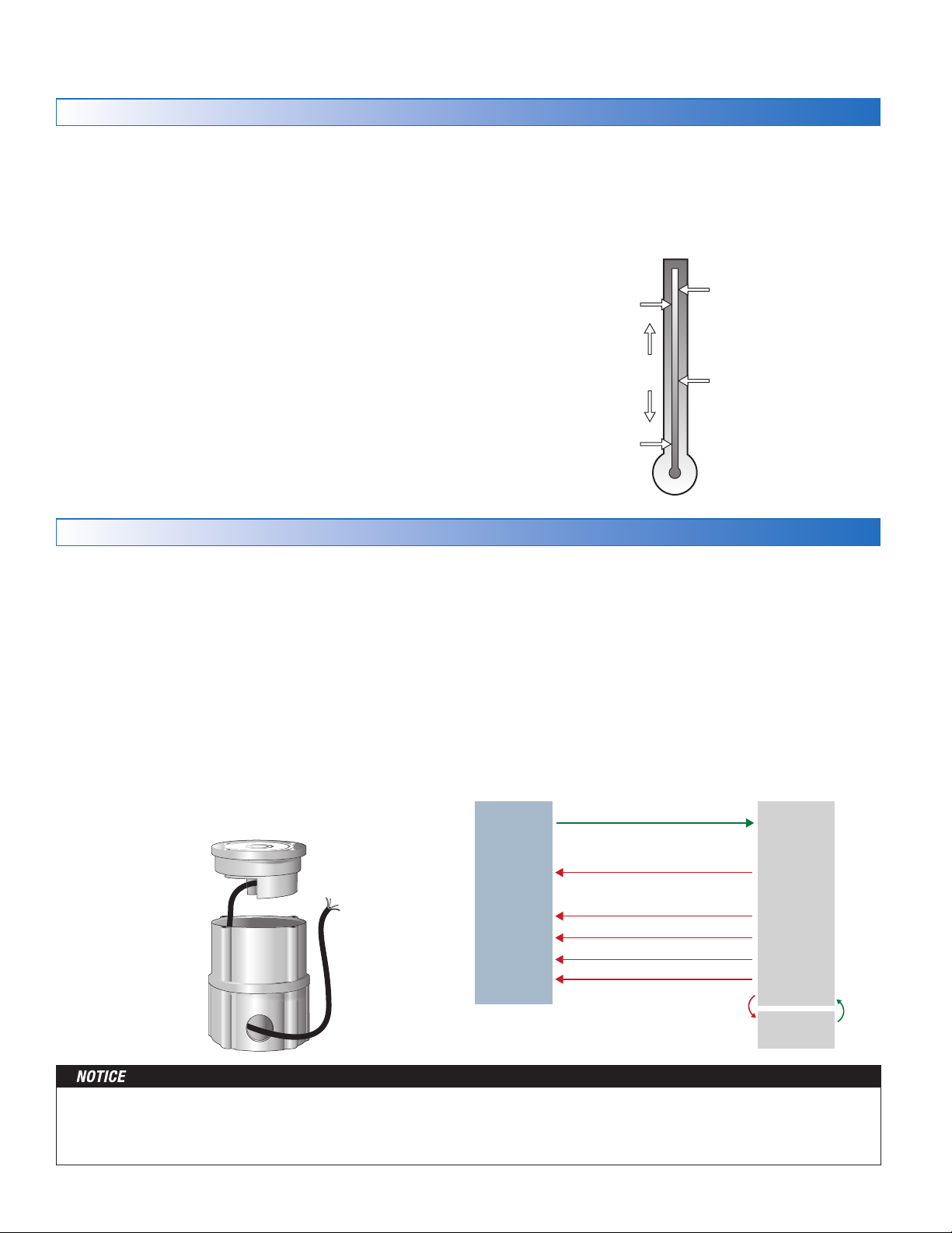
Sequence of Operation
CO
Outdoor
Temperature
Slab
Temperature
MELT
IDLE or STORM
WWSD
CWCO
Control enters
Idle and waits
for Melt Enable
Snow Melting Overview
A snow melting system can offer a safe, convenient, and cost
effective way of removing snow and ice from the snow melting
slab and similar surfaces. Safety is increased by activating
the snow melting system as soon as the snow falls rather
than waiting for mechanical snow removal after snow has
accumulated. This eliminates slip hazards and reduces the
risk of injury by mechanized snow melting equipment, thereby
reducing potential liability costs. The elimination of snow plow
equipment and corrosive salts also reduces damage to the
slab surface and to the environment. When controlled correctly,
snow melting systems can be cost competitive compared to
mechanical snow removal.
The snow melting control can operate in one of four
different ways:
Melt
Idle
Heats the slab to melt snow or ice. Default is 36°F (2°C)
Preheats the slab just below freezing to shorten the
time required to melt snow. Default is off.
Melt – Automatic Start and Stop
Automatic start and stop operation requires the installation
of a Snow/Ice Sensor 090 (65' or 20 m cable) or 094 (208'
or 63 m cable). The sensor is installed in-slab level with the
melting surface. The control continually monitors the sensor
for the presence of moisture and slab temperature conditions
in which snow or ice may be present. When moisture is
detected, the control shows “Sensor Water Status – Wet”
in the Slab Status menu. When the sensor is dry the control
shows “Sensor Water Status – Dry”. The control includes a
Sensitivity setting in the Temperatures menu that allows the
installer to adjust the amount of moisture required to start and
stop the melting operation. In areas with low amounts of dust
and/or air pollution, the sensitivity may need to be increased.
The default sensitivity setting is Auto. This setting allows the
control to automatically determine the best suitable sensitivity
Storm
Temporarily preheats the slab just below freezing to
shorten the time required to melt snow. Default is off.
Off
Snow melting system is off
The display shows the control operation in the home screen.
setting for the installation.
When moisture is detected and the slab and outdoor tempera-
tures are at or below freezing, the control will automatically
start the snow melting system. As the snow or ice melts and
the slab dries off, the sensor also dries off at the same time.
When the sensor is dry, the snow melt system automatically
shuts off. If there are low spots on the slab surface that dry
off slower than the sensor, additional melting run time can be
included by adjusting the Additional Melt Time setting in the
Temperatures menu.
If the snow melting system is manually stopped, the snow/
ice sensor must fully dry before it is able to detect a new
snow fall and automatically start the snow melting system.
090 or 094 Detects Water
Snow/Ice Sensor
090 or 094
The slab temperature must reach the slab target in order for the
system to shut off automatically. The capacity of the heat source
must be sized to ensure melting as low as the cold weather cut
off. In addition, the heat source maximum temperature setting
© 2016 tekmar 670_D - 10/16
Idle
or
Off
090 or 094 and Slab Dry and
Add Melt Time Elapses
Push STOP Button
WWSD
Mobile App Stop Button
Gateway 482 or 485 Stop Message
Enters
CWCO
Melting
Auto
Start/
Auto
Stop
Melt
Suspended
must be set to provide the full capacity of the heating appliance.
For example, boiler aquastats should be set to 180°F (82°C).
Failure to meet these requirements may result in the snow melting
system not automatically shutting off when the slab is dry.
34 of 48
Exits
CW
Page 35
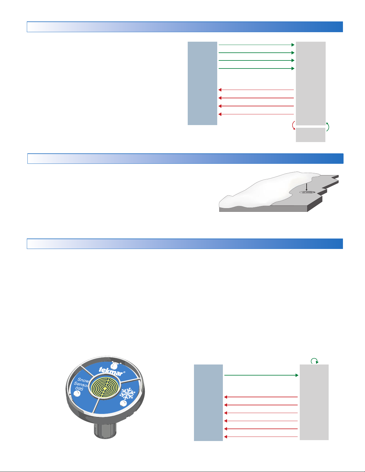
Melt – EconoMelt
Push Melt Button
CO
095 Redetects Water
When a Snow/Ice Sensor 090 or 094 is installed, the installer
can choose to select to either automatically or manually start
the snow melting system. Selecting EconoMelt to On allows
snow removal using a snow plow or shovel. The remaining thin
layer of snow or ice that mechanical snow removal methods
are unable to remove can be melted using the manual start
operation. The snow melting system stops when the sensor
is dry. The factory default for EconoMelt is Off.
Off
Mobile App Melt Button
Gateway 482 or 485 Melt Message
Manual Melt Switch
090 and Slab Dry and
Add Melt Time Elapses
Press Stop Button
WWSD
Mobile App Stop Button
Melting
Manual
Start/
Auto
Stop
Additional Melting Time
A Snow/Ice Sensor 090 or 094 automatically shuts off the
snow melting system when the water sensor is dry. Due to
the construction of the slab and the layout of the heating pipe
or electrical cable, there may be areas that do not melt completely. The Additional Melt Time setting in the Temperatures
menu allows the installer to set addition melting time after the
sensor is dry.
Melt – Automatic Start and Timed Stop
Automatic start with a timed stop operation requires the installation of a Snow Sensor 095. The sensor is aerial mounted
on a pole near the melting surface. It is highly recommended
to also install a Slab Sensor 072 (20’ or 6 m cable) or 073
(40’ or 12 m cable) in order to regulate the slab temperature
and operate the snow melting system at the highest possible
efficiency. The control continually monitors the snow sensor
for the presence of moisture and slab temperature conditions
in which snow or ice may be present. When moisture is
detected, the control will show “Sensor Water Status Wet”
in the Slab Status menu. When the sensor is dry the control
will show “Sensor Water Status Dry”. The control includes a
Sensitivity setting in the Temperatures menu that allows the
installer to adjust the amount of moisture required to start and
Enters
CWCO
Melt
Suspended
Snow Ice Sensor
Exits
CW
Dry
stop the melting operation. In areas with low amounts of dust
and/or air pollution, the sensitivity may need to be increased.
The default sensitivity setting is Auto. This setting allows the
control to automatically determine the best suitable sensitivity
setting for the installation.
When moisture is detected and both the slab and outdoor
temperatures are below the Melting setting, the control
automatically starts the snow melting system. The snow
melting system operates to heat the slab to the slab target
temperature and continues to operate until the time set by the
Manual Melt Run Time in the Temperatures menu elapses.
If the 095 re-detects water, the timer is restarted to operate
for the full run time.
Snow
Sensor 095
35 of 48
Idle
or
Off
095 Detects Water
Manual Melt Run Time Elapses
Push Stop Button
Mobile App Stop Button
Gateway 482 or 485 Stop Message
WWSD
CWCO
© 2016 tekmar 670_D - 10/16
Melting
Auto
Start/
Timed
Stop
Page 36
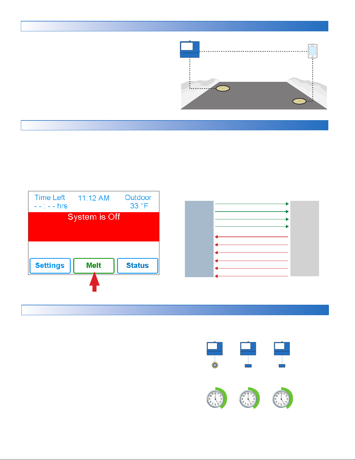
Push Melt Button
Tandem Snow/Ice Detection
Track Melt Start and Stop
Snow / Ice
Melt Time
Zone 1 Run
dd
Melt Time
The 670 can be paired together with a 654 to allow two Snow/
Ice sensors 090 or 094 or Snow Sensors 095 to be installed
for a single zone. This provides full redundancy and increases
the snow detection area.
Both sensors are used to detect snow or ice and if either
sensor is wet the snow melting zone starts melting. The
control continues to operate until both sensors are dry. This
allows snow or ice detection over a wider area. In the event
of a sensor failure, the control continues to operate normally,
giving building maintenance staff time to troubleshoot and
replace the faulty sensor if necessary.
Melt – Manual Start and Timed Stop
The snow melting system can be started manually in one of
four different methods:
• Touch the Melt button on the control display
• Through the mobile app
• Through a Gateway 482 or 485 melt request message
•
By manually connecting the Manual Melt and Com wiring
terminals 13 and 14 together.
Press Melt button to start melting operation
Once manually started and the slab warms up to the slab target,
the snow melting system runs until the time set by the Manual
Melt Run Time setting in the Temperatures menu elapses.
If a manual start has been provided and a Snow/Ice Sensor
detects water, the control changes from manual melt to
automatic operation. The snow melting system runs until the
sensor is dry and the Additional Melt Time elapses.
Mobile App Melt Button
Gateway 482 or 485 Melt Message
Idle
or
Off
Manual Melt Switch
Manual Melt Run Time Elapses
Push Stop Button
Mobile App Melt Button
Gateway 482 or 485 Stop Message
WWSD
CWCO
Melting
Manual
Start/
Timed
Stop
Melt - Tracked Start and Stop
The snow melting system can have multiple zones. Zones
have the option to track the melting run time of zone 1. This
is useful in cases where zone 1 has an automatic Snow / Ice
Sensor installed and the remaining zones do not. This allows
zones 2 to 12 to gain the functionality of automatic starting and
stopping with only one Snow / Ice sensor installed in the system.
When zone 1 detects snow or ice, it starts melting. Zones
with tracking enabled can also start melting unless priority is
selected. When the sensor in zone 1 is dry or the Manual Melt
Run Time has fully elapsed, it sends a signal to the tracked
zones that zone 1 has stopped. Each zone can continue to
operate to complete their own Additional Melt Time after which
the zone stops heating and returns to the Off or Idle operation.
Zones with priority selected start after zone 1 has finished
melting and repeat the same run time as zone 1.
© 2016 tekmar 670_D - 10/16
36 of 48
Zone 1
Sensor
Records
Run Time
Zone 2 Zone 3
Slab
Sensor
Repeats
Zone 1 Run
Time + Add
Slab
Sensor
Repeats
Time + A
Page 37

Idle Operation
Then
When the snow melting system starts from a cold temperature,
there may be a long time delay before the slab is warm enough
to melt snow. This time delay allows snow to accumulate on
the slab which is not acceptable in some commercial and
institutional applications. To decrease the start-up time, the slab
can be pre-heated to maintain a minimum temperature. This
is known as the Idle temperature. Idling requires large energy
consumption and is generally recommended for institutional
and/or commercial installations where safety concerns are
paramount. The display shows "System is Idling" when the
control is in idle operation.
When designing a snow melting system, an engineer may
specify the amount of allowed snow accumulation as the
Snow-Free Area Ratio. There are three different levels. A
Snow-Free Area Ratio of 1 is defined as a system that melts
all snow as it falls with no allowed accumulation. This requires
that the Idle temperature be set just below freezing. Examples
of these types of applications include:
• Hospital emergency areas
• Helicopter landing pads
• Parking garage ramps
A Snow-Free Area Ratio of 0.5 is defined as a system with
partial snow accumulation on the slab but not in all areas.
These types of systems may also use Idling but usually set
at a temperature several degrees below freezing to reduce
energy consumption. Applications may include:
• Steep residential driveways
• Commercial sidewalks
• Loading docks
A Snow-Free Area Ratio of 0 is defined as a system that
allows snow accumulation. These systems operate the snow
melting system from a cold start resulting in the lowest energy
consumption costs and the longest times to start melting snow.
In this case set the Idle to off. This is recommended for most
residential applications such as:
• Flat residential driveways
• Patios
• Residential sidewalks
Some systems are designed for keeping a slab surface free of
ice rather than free of snow. The most common applications
include:
• Car wash bays and aprons
• Aircraft hanger aprons
• Turf conditioning on golf course greens
These systems require the use of Idling at or near freezing
throughout the winter and may result in high energy consumption.
Storm Operation
The Storm operation combines the benefits of a fast response
time together with lower operating costs. Typically the storm
temperature is set below freezing to maximize energy savings.
In the event that snow falls and is detected by a Snow/Ice
Sensor or a Snow Sensor or the system is manually started, the
snow melt system heats the slab up to the melting temperature
and completes a melting cycle.
Should no snow fall during the storm time period, the control
exits Storm operation and returns to Off.
The Storm operation is set up by setting the Storm temperature
and the Storm Run Time in the Temperatures menu.
Auto Storm
The control automatically checks an Internet weather service
to determine the snowfall forecast for a region based upon the
US ZIP or Canadian postal code. When the Storm feature is
on and snowfall is predicted, the control automatically heats
the slab to the storm setting.
When connected using tekmarNet, a 670 can automatically
start the storm operation on a Snow Melting Control 654. To
do this set the 670 and the 654 to use the same Storm Group
number.
--------------------------------------
If
forecast
Manual Storm
The storm operation can be manually started by a User Switch
480 or 481 or a Gateway 482 or 485. The manual storm uses
the Storm Group number in the tekmarNet menu.
Setup Procedure
Step 1: Set the 670 Storm Group number from 1 to 12. The
default is 12.
Step 2: Set the User Switch or the Gateway to use the corre
sponding Storm Group number.
When the User Switch button is pressed, the 670 will enter
the Storm Operation. Likewise, activating the Storm Group
on the Gateway cause the 670 to enter the Storm Operation.
-----------------------------------
Auto Storm (Weather Predictive)
User Switch Button
Gateway Storm Enable
Storm Run Time Elapses
User Switch Button
Gateway Storm Disable
Away scene
WWSD
CWCO
StormOff
-
37 of 48
© 2016 tekmar 670_D - 10/16
Page 38
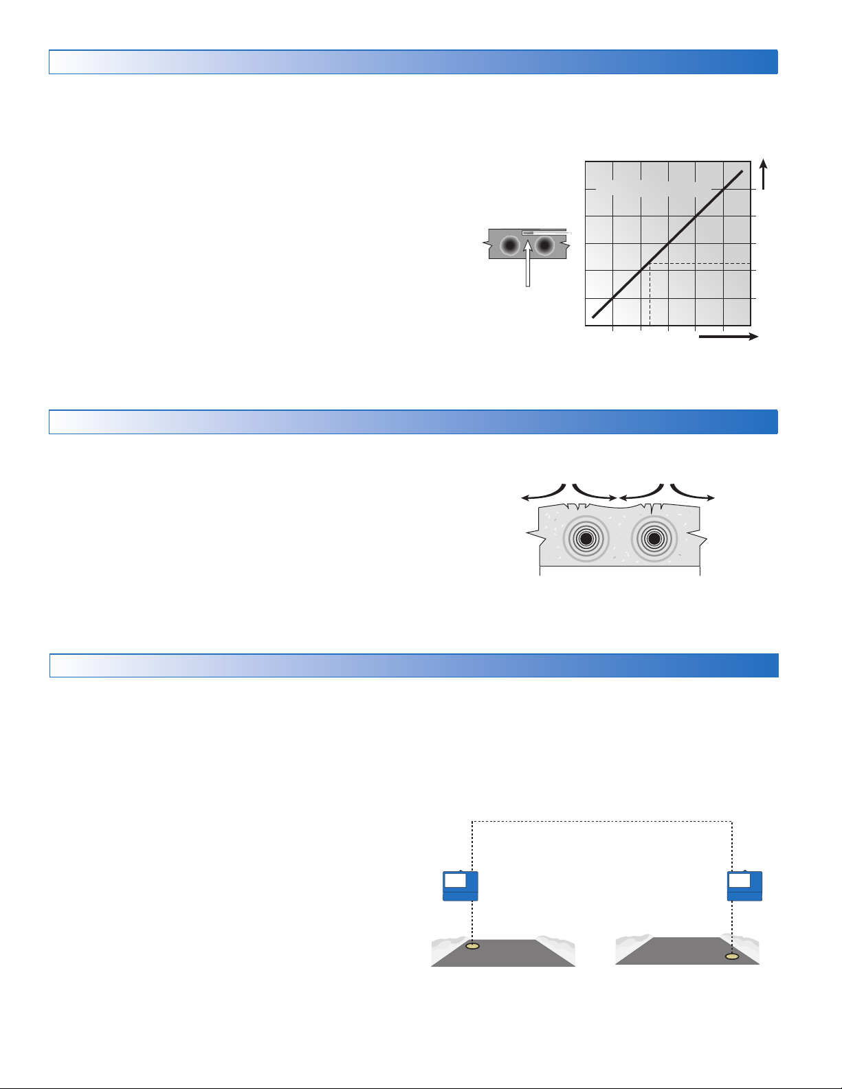
tekmarNet
tensile stresses
Slab Temperature Control
Sur
Increasing Slab Core T
Slab Surface Temperature is Constant
Controlling the slab temperature is critical to minimizing the
cost of snow melting. This requires that either a Snow/Ice
Sensor 090 or 094 or a Slab Sensor 072 or 073 is installed.
The Snow/Ice Sensor contains a built-in slab temperature
sensor. While the control can operate without a slab sensor
installed, operating costs are much higher.
The slab is operated using slab outdoor reset. As the outdoor
temperature gets colder, the heat loss of the slab increases.
In order to keep the slab surface at a constant temperature
while operating, the inner core of the slab must be heated
above the melt, idle or storm temperature setting. The amount
that the slab inner core temperature is above the melt, idle
or storm setting is proportional to the outdoor temperature.
Since the slab sensor is installed below the surface of the
slab, it is not measuring the true slab surface temperature but
rather the inner core temperature. The control automatically
compensates for this temperature difference. The Slab item in
Slab Protection
In a hydronic snow melting system, the boiler or heating
plant capacity may be much larger than the load of the snow
melting zones. This can result in large temperature differentials
between the supply water temperature and the slab creating
large tensile stresses on the slab. Concrete is weak to tensile
forces and when repeatedly exposed to tensile loads the
concrete may crack. This may be prevented by selecting
the Slab Protection setting in the System Setup menu to On.
The control measures and limits the temperature differential
between the supply water and the slab.
the Status menu displays the actual measured temperature,
so it is normal to view slab temperatures that exceed the melt,
idle, or storm temperature settings.
Slab Outdoor ResetSlab Outdoor Reset
face temperature = 35ϒF
emperature
Core (sensor)
is warmer
Decreasing Air Temperature
Snow Melt Zones and Priority
Dividing a system into a number of snow melting zones and
prioritizing the zone operation reduces the size requirements
of the hydronic heating plant or the amperage of the electrical
service panel. This results in lower initial capital cost of the
snow melting system. The trade off is that some snow melt
zones may not be able to melt as soon as the snow fall begins
and the user must tolerate snow accumulation on the slab.
The snow melt system using Snow Melting Control 654 and
670 may have up to 12 snow melt zones. Zone 1 has the
highest priority and zone 12 has the lowest. The priority
setting in the tekmarNet® menu allows the installer to select
the level of zone priority for the entire snow melt system.
Changing the priority setting on one control will update on
all other snow melt controls at the same time. The zone
priority has 3 setting levels. There is some risk that lower
priority zones may ice up when they are shut off by the higher
priority zone. For example, if a high priority zone should finish
melting and allow a lower priority zone to start melting, and
then a new snow fall occurs, the high priority zone will shut
off the lower priority zones. This may potentially allow the
lower priority zones to ice over. The limitations of zoning and
© 2016 tekmar 670_D - 10/16
using priority must be carefully considered and discussed
with the building owners and occupants when designing the
snow melting system.
Priority does not apply when the application mode is set to
Boiler. In this mode, the boiler is dedicated to a single snow
melting zone so priority is no longer applicable.
670
Snow Melt
Zone 1
38 of 48
Snow Melt
Zone 2
670
Page 39
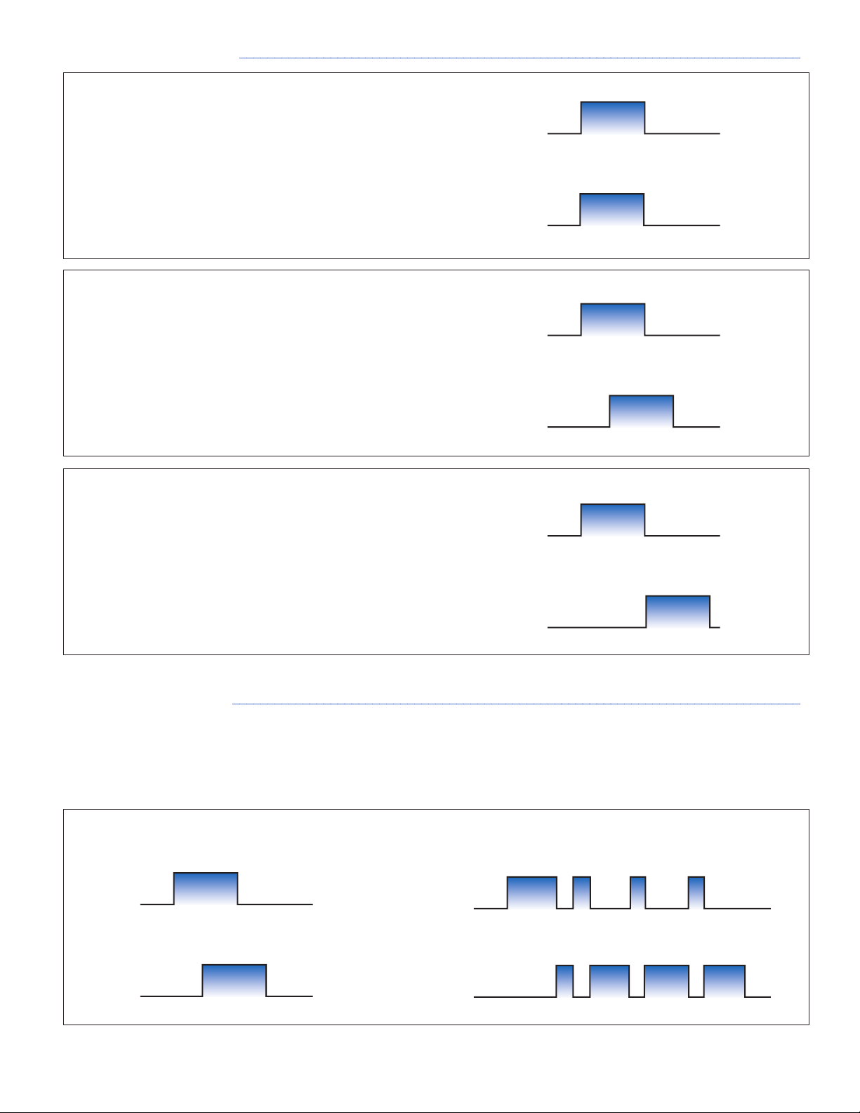
Hydronic Priority Levels
MELT
OFF
MEL
OFF
MELT
OFF
MEL
OFF
MELT
OFF
MEL
OFF
MELT
OFF
MEL
OFF
Zone 1 Relay
ON
OFF
Zone 2 Rela
ON
OFF
--------------------------------------------------------------------------------
Priority = None
All zones have the same priority and can operate at the same time.
This setting is recommended when the boiler plant capacity is
sized larger than the heat loss of all zones at design conditions.
Priority = Conditional
The zone with the lower priority starts melting when the
zone with higher priority is warm enough to melt snow or ice.
This setting is recommended when the boiler plant capacity
is sized to be larger than the heat loss of each zone with
some extra capacity.
Zone 1
T
Zone 2
Zone 1
T
Zone 2
Priority = Full
The zone with the lower priority starts melting once the
zone with higher priority has finished melting all snow or
ice from the slab.
This setting is recommended when the boiler plant capacity
is sized to be the same as the heat loss of each zone at
design conditions.
Electric Priority Levels
---------------------------------------------------------------------------------
Electric snow melting offers three levels of priority: None,
Conditional and Full. The None and Full priority options function
the same as with the hydronic operation. The Conditional
priority is unique to electrical operation. The highest priority
zone operates first. Whenever the highest priority zone shuts
Zone 1
T
Zone 2
off its relay, the lower priority zone is allowed to start melting
and close its relay. Only one electrical relay is allowed to be
on at any time. This eliminates large instantaneous demands
and avoids surcharges from the electrical utility.
Zone 1
y
T
Zone 2
39 of 48
© 2016 tekmar 670_D - 10/16
Page 40

Warm Weather Shut Down
During warm weather, the slab is warm enough to naturally
melt snow or ice. The control has a Warm Weather Shut Down
(WWSD) setting in the Temperatures menu that prevents the
control from entering Melt, Idle or Storm operation in order to
conserve energy. The control shows, "System is Off – Warm
Weather Shut Down" on the display when WWSD is in effect.
Automatic (Auto)
The control enters WWSD when both the slab temperature
and the outdoor temperature exceed the Melting Setpoint
temperature setting by more than 2°F (1°C).
Cold Weather Cut Off
Maintaining the melting or idling setpoint temperature during
extremely cold temperatures is not only expensive but may
be impossible if the heat loss of the slab exceeds the input
capacity of the heating plant or electric cable. The control
turns the snow melting system off when the outdoor air
temperature drops below the Cold Weather Cut Off (CWCO)
temperature and the slab is below freezing. This is a safety
and energy saving measure. The control shows, "System is
Manual WWSD
The control enters WWSD when the outdoor air temperature
exceeds the WWSD setting by 1°F (0.5°C) and when the
slab temperature exceeds 34°F (1°C). The control exits
WWSD when the outdoor air temperature falls 1°F (0.5°C)
below the WWSD setting or if the slab temperature falls
below 34°F (1°C). This allows the Melting Setpoint setting
to be set higher than the WWSD. This is useful when high
slab temperatures are required to melt the snow or ice. An
example of this are installations using paving bricks on top
of sand and concrete layers.
Off – Cold Weather Cut Off" on the display when CWCO is
in effect. When the temperature reaches the CWCO setting
in an actively melting system with an 090 or 094, melting is
suspended until the outdoor temperature rises above the
CWCO setting at which time melting is resumed. If an 090
or 094 is not installed, melting is stopped when CWCO is in
effect and melting does not resume when the temperature
rises above the CWCO setting.
Time Clock
The control has a built-in time clock that can be set manually
or automatically by the Internet. A battery-less backup allows
the control to keep time for up to 4 hours without power. The
time clock supports automatic adjustment for Daylight Saving
Away Operation
While on vacation and away from a building, it may not be
necessary to operate the snow melting system. The away
feature allows the user to shut off the snow melting system to
maximize energy savings. The Away feature can be activated
through the:
tekmarNet Scene Operation
The tekmarNet system supports up to 8 scenes.
The 670 supports tekmarNet scenes 1 (normal operation)
and 2 (away).
During tekmarNet scenes 3 through 8, the 670 remains in
scene 1 (normal operation).
Time (DST) once the day, month and year are entered. Use
the Time menu to set the correct time, day, month and year. If
the time and date is set incorrectly, the control may be unable
to communicate to the mobile app.
• Away menu
• tekmar Connect mobile app
• tekmarNet User Switch 480 or 481
• tekmarNet Gateway 482 or 485
© 2016 tekmar 670_D - 10/16
40 of 48
Page 41

Application Modes
The snow melting control can operate either an electric or
a hydronic snow melting system. A hydronic system can be
categorized as boiler, mixing, boiler and mixing, or pulse
width modulation zone operation. A dedicated boiler only
provides heat for the snow melting system. A shared boiler
provides heat for the snow melting system in addition to the
space heating and/or a domestic hot water system. These
choices affect which Application Mode is selected in the
System Setup menu:
Electric Operation
The Application Mode should be set to Electric when operating
an electric heating cable. The control operates the heat relay
on a 20-minute pulse width modulation cycle. The heat relay
in turn activates a line voltage electrical contactor to energize
the electrical cable heater installed in the slab. The relay on
time is determined by the calculated slab target and by the
measured slab temperature reading. As the slab temperature
reaches the slab target, the on-time per cycle of the relay is
reduced to prevent the slab temperature from overshooting.
If no slab sensor is installed the relay remains on 100% of the
time until the Melt operation has completed. Idle and Storm
operation are not available when a slab sensor is not installed.
The electric operation requires the installation of an outdoor
sensor. A slab sensor is highly recommended in order to
reduce operating costs.
• PWM Zone Pulse Width Modulation Zone Operation
• Boiler Boiler Operation
• Mixing Mixing Operation
• Boiler+Mix Boiler and Mixing Operation
• Electric Electrical Operation
Relay operation:
•
Heat relay — cycles on and off using
• System pump — not used
• Primary pump — not used
• Boiler stage 1 — not used
• Boiler stage 2 — not used
Pulse Width Modulation
Pulse Width Modulation Zone Operation
The Application Mode should be set to Pulse Width Modulation
(PWM) Zone when the snow melting system is warmed from
a heat source that is shared with other loads in a building.
The control operates the system pump to operate continuously
during melt, idle and storm operation. The boiler stage 1 relay
operates on a 20-minute pulse width modulation cycle. The relay
on time is determined by the calculated slab target and by the
measured slab temperature reading. As the slab temperature
reaches the slab target, the on time per cycle of the relay is
reduced to prevent the slab temperature from overshooting.
If no slab sensor is installed the heat relay remains on 100%
of the time until the Melt operation has completed. Idle and
Storm operation are not available when a slab sensor is not
installed. The PWM Zone operation requires the installation
of an outdoor sensor. A slab sensor is highly recommended
in order to reduce operating costs.
Relay operation:
• System pump — operates continuously during melting,
idling or storm
• Heat relay — cycles on/off using Pulse Width Modulation to
control the slab temperature
• Boiler stage 1 — cycles on/off using Pulse Width Modulation
to control the slab temperature
• Boiler stage 2 — not used
41 of 48
© 2016 tekmar 670_D - 10/16
Page 42
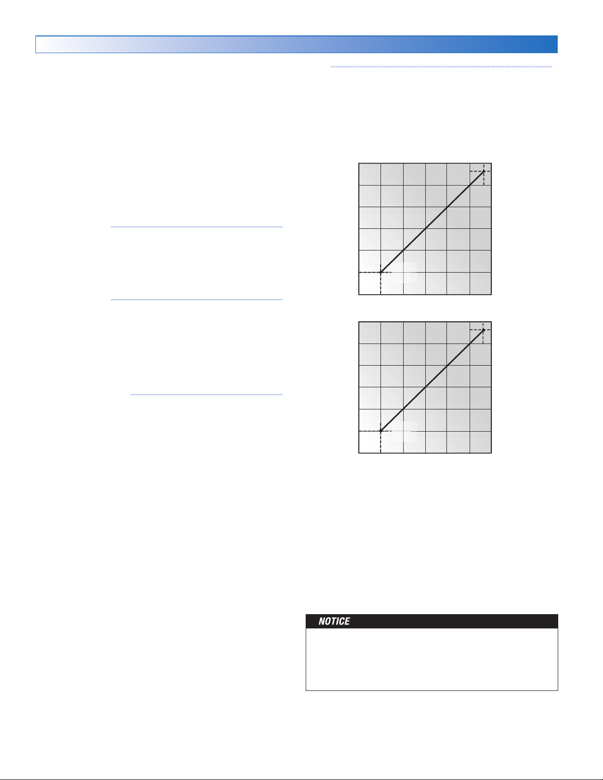
Boiler Operation
Supply Water Temperature
EMS Current mA
Supply Water Temperature
The Application Mode should be set to Boiler when the snow
melting system has a dedicated boiler or heat source and there
is no mixing device. The boiler is piped primary-secondary
to the snow melting loop, thereby allowing the boiler to fire
on and off while allowing continuous flow through the snow
melting system loop. The control calculates a Boiler Target
based upon the Slab Target, which in turn is based upon the
measured outdoor temperature and the Melt, Idle or Storm
EMS
---------------------------------------------
When the boiler is required to operate, the control's boiler
modulation output is adjusted to an appropriate analog signal
corresponding to the boiler target temperature and then turns
on the boiler stage 1 relay. The analog signal is proportional
to the boiler target in a linear line defined by the EMS Signal
Minimum, the EMS Low Temperature, and the EMS High
Temperature settings.
temperature setting. The boiler is fired to maintain the Boiler
Target at the Boiler Supply Sensor location. The control can
operate a boiler in one of four different methods: modulating
boiler, 1 stage, 2 stage and EMS. The Boiler Target is shown
EMS
HIGH
TEMP
10V(dc)
in the System Status menu. Settings for the boiler operation
are located in the Boiler Setup menu.
1 Stage Boiler
-----------------------------------
The control turns the boiler stage 1 relay on or off to fire the
boiler and maintain the Boiler Target temperature. The boiler
supply temperature operates on a differential that is half above
and half below the boiler target. The status of the boiler is
shown in the System Status menu.
2 Stage Boiler
-----------------------------------
EMS
SIGNAL
MIN
EMS
LOW
TEMP
EMS Voltage V (dc)
The control turns the boiler stage 1 and 2 relays on or off
to fire a single boiler in order to maintain the Boiler Target
temperature. The boiler supply temperature operates on a
differential that is half above and half below the boiler target.
EMS
HIGH
TEMP
20mA
The boiler staging is operated automatically using PID logic.
The status of the boiler stages 1 and 2 is shown in the System
Status menu.
Modulating Boiler
-------------------------------
The control can operate a single modulating boiler using
the modulating output and the boiler stage 1 contact. The
control operates the boiler by first switching the boiler stage 1
contact to allow the modulating boiler to go through the ignition
sequence. The boiler stage 1 contact may not be required
EMS
SIGNAL
MIN
EMS
LOW
TEMP
on all modulating boilers. A 0-10 V (dc) or 4-20 mA analog
signal is then used to modulate the boiler firing rate starting
at 50% (5 V (dc) or 12 mA signal) for 30 seconds. After the
30-second delay has elapsed, the control will then allow the
boiler to modulate down to the Boiler Minimum Modulation
setting and hold it there for the Boiler Modulation Delay time
setting. After the modulation delay has elapsed, the control
uses PID logic to change the boiler firing rate signal in order to
satisfy the boiler target temperature. When the firing rate signal
is reduced down to the minimum modulating setting and the
Relay operation:
System pump — operates continuously during melting,
idling or storm
Heat relay — cycles on/off with boiler stage 1
Boiler stage 1 — cycles on/off based on boiler target
Boiler stage 2 — cycles on/off based on boiler target
when using a two-stage boiler, otherwise off.
boiler supply temperature exceeds the boiler target by 1/2 of
the differential, the control will shut off the boiler burner. The
modulating signal output is shown by the Boiler Output in the
System Status menu.
The Boiler Modulation Delay setting is determined by the boiler
manufacturer. It is the amount of time that the burner must
operate before the internal boiler control allows an external
signal to operate the burner.
The Boiler Motor Speed sets the rate at which the modulating
electrical signal can change. For most modulating boilers with
The boiler operator, or aquastat, remains in the burner
circuit and acts as a secondary upper limit on the boiler
temperature. It is recommended to set the boiler aquastat
temperature to at least 180°F (82.0°C) in order to prevent
short cycling of the burner.
an ECM fan, the boiler motor speed can be set to 30 seconds.
For commercial boilers with a mod motor, set the boiler motor
speed according to the time required by the mod motor to
travel from the closed to open position.
© 2016 tekmar 670_D - 10/16
42 of 48
Page 43

Mixing Operation
The Application Mode should be set to Mixing when a mixing
valve or a mixing injection pump is installed with a shared
boiler plant. Four mixing options are available:
• Floating action mixing valve
• Variable-speed injection pump
• Analog mixing using 0-10 V (dc)
• Analog mixing using 4-20 mA
The control calculates the Slab Target temperature based on
the outdoor air temperature and the Melting, Idling or Storm
Setpoint. The control then determines the Mix System Target
based on the Slab Target requirements. The Mix Maximum setting
limits the upper temperature of the Mix System Target. The
Mix System Target is shown in the System Status menu.
For design and sizing of the variable-speed injection mixing
pump, please refer to the Essay E021.
Relay operation:
•
System pump — operates continuously during melting,
idling or storm
Boiler and Mixing Operation
The Application Mode should be set to Boiler+Mix when a
mixing valve or a mixing injection pump is installed to regulate
the supply water temperature to the snow melting system with
a dedicated boiler plant. In this case, the control operates both
the mixing device and the dedicated boiler at the same time.
The control calculates the Slab Target temperature based on the
outdoor air temperature and the Melting, Idling or Storm Setpoint.
The control then determines the Mix System Target based on
the Slab Target requirements. The control then determines the
required Boiler Target that is required to meet the Mix System
Target. Refer to the Boiler and Mixing Operation sections for
detailed information on the boiler and mixing operation.
Relay operation:
•
System pump — operates continuously during melting,
idling or storm
• Heat relay — operates when the boiler is firing
• Heat relay — closes when the mixing valve is open or the
variable speed injection pump is operating.
•
Boiler stage 1 — turns on when the valve is open or the
variable speed injection pump is operating.
• Boiler stage 2 — not used
If using Floating Action Mixing
• Floating action open — contact closes momentarily when
pulsing actuator open
•
Floating action closed — contact closes momentarily when
pulsing actuator closed
If using Variable Speed Injection Mixing
•
Injection Mixing Output — a variable speed signal is
supplied to the pump
If using Analog Mixing
• Analog Mixing Output — a signal ranges between 0-10 V
(dc) or 4 -20 mA
• Boiler stage 1 — cycles on/off based on boiler target
• Boiler stage 2 — cycles on/off based on boiler target when
using a two-stage boiler, otherwise off.
If using Floating Action Mixing
•
Floating action open — contact closes momentarily when
pulsing actuator open
•
Floating action closed — contact closes momentarily when
pulsing actuator closed
If using Variable Speed Injection Mixing
•
Injection Mixing Output — a variable speed signal is supplied
to the pump
If using Analog Mixing
•
Analog Mixing Output — a signal ranges between 0-10 V
(dc) or 4 -20 mA
Outdoor Sensor
The outdoor air temperature is required for all application
modes. The control has the option to measure an outdoor air
sensor or the outdoor temperature can be provided through
Exercising
In a hydronic snow melting system, the control operates the
system, primary, boiler, variable speed injection mixing pump
and mixing valve every 3 days to prevent pump and valve
seizure.
Post Purge
The boiler or heat source is shut off and the snow melting
system continues to operate for 20 seconds to post purge heat
from the boiler to the load.
the tekmarNet system or through the Internet weather service.
This is selected by the Outdoor Sensor setting in the System
Setup menu.
43 of 48
© 2016 tekmar 670_D - 10/16
Page 44

Troubleshooting
!
It is recommended to complete all wiring to ensure trouble free operation. Should an error occur, simply follow these steps:
1. Find: If the control shows the Warning Symbol on the screen, it is indicating a problem on the system.
2. Identify: Press the Warning Symbol to view the error code.
3. Solve: Use the chart below to match the error code to the one on the control. Use the description to solve
the problem.
Error Messages (1 of 4)
Description
TEMPERATURE MENU SAVE ERROR
The control failed to read the Temperatures menu settings from memory and has reloaded the factory default settings. The
control stops operation until all settings in the Temperatures menu are checked.
To clear the error, set the access level to Installer and check all settings in the Temperatures menu.
SYSTEM SETUP MENU SAVE ERROR
The control failed to read the System Setup menu settings from memory and has reloaded the factory default settings. The
control stops operation until all settings in the System Setup menu are checked.
To clear the error, set the access level to Installer and check all settings in the System Setup menu.
BOILER SETUP MENU SAVE ERROR
The control failed to read the Boiler Setup menu settings from memory and has reloaded the factory default settings. The control
stops operation until all settings in the Boiler Setup menu are checked.
To clear the error, set the access level to Installer and check all settings in the Boiler Setup menu.
MIXING SETUP MENU SAVE ERROR
The control failed to read the Mixing Setup menu settings from memory and has reloaded the factory default settings. The control
stops operation until all settings in the Mixing Setup menu are checked.
To clear the error, set the access level to Installer and check all settings in the Mixing Setup menu.
tekmarNet MENU SAVE ERROR
The control failed to read the tekmarNet menu settings from memory and has reloaded the factory default settings. The control
stops operation until all settings in the tekmarNet menu are checked.
To clear the error, set the access level to Installer and check all settings in the tekmarNet menu.
WiFi MENU SAVE ERROR
The control failed to read the WiFi menu settings from memory and has reloaded the factory default settings. The control stops
operation until all settings in the WiFi menu are checked.
To clear the error, set the access level to Installer and check all settings in the WiFi menu.
MAX MELT DAYS ERROR
The control has operated in melting for the time set by Maximum Melt Days setting located in the System Setup menu. This error
is usually created when there is a mechanical system failure resulting in the snow melt slab not heating correctly.
Clear the error message by touching the Cancel button while viewing the error message. Use the Manual Override menu to
manually check that each component of the mechanical system is operating correctly.
If necessary, change the Maximum Melt Days setting to a longer time period or to Off.
OUTDOOR SENSOR OPEN CIRCUIT ERROR
Due to an open circuit, the control is unable to read the Outdoor Sensor 070 on terminals 16 and 18. This error may also occur
when using the outdoor temperature from a tekmarNet system.
The control continues to operate and assumes an outdoor temperature of 32°F (0°C). Energy saving features such as Warm
Weather Shut Down (WWSD) and Cold Weather Cut Off (CWCO) are disabled.
Check the outdoor sensor wire for open circuits according to the sensor installation manual. It may be necessary to replace the
outdoor sensor. Once the error has been corrected, the error message automatically clears.
OUTDOOR SENSOR SHORT CIRCUIT ERROR
Due to a short circuit, the control is unable to read the Outdoor Sensor 070 on terminals 16 and 18.
The control continues to operate and assumes an outdoor temperature of 32°F (0°C). Energy saving features such as Warm
Weather Shut Down (WWSD) and Cold Weather Cut Off (CWCO) are disabled.
Check the outdoor sensor wire for short circuits according to the sensor installation manual. It may be necessary to replace the
outdoor sensor. Once the error has been corrected, the error message automatically clears.
© 2016 tekmar 670_D - 10/16
44 of 48
Page 45

Error Messages (2 of 4)
Description
MIX SUPPLY SENSOR OPEN CIRCUIT ERROR
Due to an open circuit, the control is unable to read the Mix Supply Sensor 082 on terminals 15 and 16. The control stops
operation and does not provide any heat.
Check the system supply sensor wire for open circuits according to the sensor installation manual. It may be necessary to replace
the mix supply sensor. Once the error has been corrected, the error message automatically clears.
MIX SUPPLY SENSOR SHORT CIRCUIT ERROR
Due to a short circuit, the control is unable to read the Mix Supply Sensor 082 on terminals 15 and 16. The control stops operation
and does not provide any heat.
Check the system supply sensor wire for short circuits according to the sensor installation manual. It may be necessary to replace
the mix supply sensor. Once the error has been corrected, the error message automatically clears.
BOILER SENSOR OPEN CIRCUIT ERROR
Due to an open circuit, the control is unable to read the Boiler Sensor 082 on terminals 16 and 17. When application mode is set
to boiler or boiler+mix the control stops operation. In all other application modes, the control continues to heat the snow melting
system but does not control the boiler operating temperature.
Check the boiler sensor wire for open circuits according to the sensor installation manual. It may be necessary to replace the
boiler sensor. Once the error has been corrected, the error message automatically clears.
BOILER SENSOR SHORT CIRCUIT ERROR
Due to a short circuit, the control is unable to read the Boiler Sensor 082 on terminals 16 and 17. When application mode is set
to boiler or boiler+mix the control stops operation. In all other application modes, the control continues to heat the snow melting
system but does not control the boiler operating temperature.
Check the boiler sensor wire for short circuits according to the sensor installation manual. It may be necessary to replace the
boiler supply sensor. Once the error has been corrected, the error message automatically clears.
SLAB SENSOR OPEN CIRCUIT ERROR
Due to an open circuit, the control is unable to read the Slab Sensor 072 or 073 on terminals 7 and 10. Idling and storm are
disabled and energy saving features such as Warm Weather Shut Down (WWSD) and Cold Weather Cut Off (CWCO) are
operated using the outdoor temperature only.
Check the slab sensor wire for open circuits according to the sensor installation manual. It may be necessary to replace the slab
sensor. Once the error has been corrected, the error message automatically clears.
If the slab sensor has been intentionally removed, set the slab sensor setting in the system setup menu to off.
SLAB SENSOR SHORT CIRCUIT ERROR
Due to a short circuit, the control is unable to read the Slab Sensor 072 or 073 on terminals 7 and 10. Idling and Storm are disabled
and energy saving features such as Warm Weather Shut Down (WWSD) and Cold Weather Cut Off (CWCO) are operated using
the outdoor temperature only.
Check the slab sensor wire for short circuits according to the sensor installation manual. It may be necessary to replace the slab
sensor. Once the error has been corrected, the error message automatically clears.
SNOW SENSOR YELLOW WIRE OPEN CIRCUIT ERROR
Due to an open circuit, the control is unable to read the yellow wire connected to the Snow/Ice Sensor 090 or 094, or the Snow
Sensor 095 on terminals 7 and 9. The control can no longer automatically detect snow or ice, but manual start of the snow
melting system is still available.
Check the snow/ice sensor or snow sensor yellow and black wires and any wire splices for open circuits according to the
sensor installation manual. It may be necessary to replace the sensor. Once the error has been corrected, the error message
automatically clears.
SNOW SENSOR BLUE WIRE OPEN CIRCUIT ERROR
Due to an open circuit, the control is unable to read the blue wire connected to the Snow/Ice Sensor 090 or 094, or the Snow
Sensor 095 on terminals 7 and 8. The control can no longer automatically detect snow or ice, but manual start of the snow
melting system is still available.
Check the snow/ice sensor or snow sensor blue and black wires and any wire splices for open circuits according to the sensor
installation manual. It may be necessary to replace the sensor. Once the error has been corrected, the error message automatically
clears.
SNOW SENSOR BLUE WIRE SHORT CIRCUIT ERROR
Due to a short circuit, the control is unable to read the blue wire connected to the Snow/Ice Sensor 090 or 094, or the Snow
Sensor 095 on terminals 7 and 8. The control can no longer automatically detect snow or ice, but manual start of the snow
melting system is still available.
First check the snow/ice sensor or snow sensor for dirt or debris. The ring structure of the sensor may need cleaning with hot
soapy water and a nylon brush. Rinse with water. Second, check the snow/ice sensor or snow sensor blue and black wires and
any wire splices for short circuits according to the sensor installation manual. It may be necessary to replace the sensor. Once
the error has been corrected, the error message automatically clears.
45 of 48
© 2016 tekmar 670_D - 10/16
Page 46

Error Messages (3 of 4)
Description
SNOW SENSOR BROWN WIRE OPEN CIRCUIT ERROR
Due to an open circuit, the control is unable to read the brown wire connected to the Snow/Ice Sensor 090 or 094 on terminals 7
and 10. Idling and Storm is disabled and energy saving features such as Warm Weather Shut Down (WWSD) and Cold Weather
Cut Off (CWCO) are operated using the outdoor temperature only.
Check the snow/ice sensor brown and black wires for open circuits according to the sensor installation manual. It may be
necessary to replace the sensor. Once the error has been corrected, the error message automatically clears.
SNOW SENSOR BROWN WIRE SHORT CIRCUIT ERROR
Due to a short circuit, the control is unable to read the brown wire connected to the Snow/Ice Sensor 090 or 094 on terminals 7
and 10. Idling and Storm is disabled and energy saving features such as Warm Weather Shut Down (WWSD) and Cold Weather
Cut Off (CWCO) are operated using the outdoor temperature only.
Check the snow/ice sensor brown and black wires for short circuits according to the sensor installation manual. It may be
necessary to replace the sensor. Once the error has been corrected, the error message automatically clears.
SNOW/ICE SENSOR ERROR
The control is unable to properly detect the Snow/Ice Sensor 090 or 094 on terminals 6, 7, 8, 9 and 10. The control can no longer
automatically detect snow or ice, but manual start of the snow melting system is still available.
Check the snow/ice sensor brown, yellow, red and black wires according to the sensor installation manual. It is important to check
any cable splices for loose wiring connections. It may be necessary to replace the sensor. Once the error has been corrected,
the error message automatically clears.
SNOW SENSOR ERROR
The control is unable to properly detect the Snow Sensor 095 on terminals 6, 7, 8, and 9. The control can no longer automatically
detect snow but manual start of the snow melting system is still available.
Check the snow sensor yellow, red and black wires according to the sensor installation manual. It may be necessary to replace
the sensor. Once the error has been corrected, the error message automatically clears.
© 2016 tekmar 670_D - 10/16
46 of 48
Page 47

Frequently Asked Questions
Symptom Look For... Corrective Action
Touchscreen is
off
System pump
always on
Blue short
Slab is
above melt
temperature
System running
with no snow
Snow on slab
but system did
not start
Power to control
Display shows Idle
Dirt or salt on snow/
ice sensor
Slab Target
System is Idling
System is Melting
Remaining Run
Time
Slab and Slab
Target
System is Off
Use electrical meter to measure 115 V (ac) voltage on input power L and N
terminals.
Idle operation requires that the system pump operate continuously while below the
melting temperature setting.
The snow/ice sensor requires regular cleaning. Avoid using road salt on the snow
melting slab.
The slab is heated to the slab target.
Idling heats the slab when the temperature falls below the Idle temperature.
During cold weather cut off (CWCO), the system is shut off. If it shuts off during a
melt cycle, the system resumes melting once the outdoor temperature is above
CWCO.
System manually started.
The slab must reach the slab target temperature in order for the system to shut off.
Lower the cold weather cut off (CWCO) or increase the boiler aquastat setting.
System has been manually stopped and the automatic snow/ice sensor never dried,
thereby preventing the system from automatically starting.
WARNING: This product contains chemicals known to the
California to cause cancer and birth defects or other reproductive harm.
For more information: Watts.com/prop65
State of
47 of 48
© 2016 tekmar 670_D - 10/16
Page 48

Technical Data
WiFi Snow Melting Control 670 Boiler & Mixing / Electric
Literature 670_A, 670_C, 670_D, 670_J, 670_U
Control Microprocessor control. This is not a safety (limit) control.
Packaged weight 4.3 lb. (1960 g)
Dimensions 6-5/8" H x 7-9/16" W x 2-13/16" D (170 x 193 x 72 mm)
Display 3.5", color touchscreen
Enclosure Blue PVC plastic, NEMA type 1
Approvals
Ambient conditions -4 to 122°F (-20 to 50°C), < 90% RH non-condensing, outdoor use permitted when used in NEMA 3 enclosure
Power supply 115 V (ac) ±10%, 60 Hz, 20 VA
Relays 230 V (ac), 5 A, 1/3 hp
Boiler modulating output 0-10 V (dc) 500 Ω min impedance / 4-20 mA 1 kΩ max impedance
Injection mixing pump 230 V (ac), 2.4 A 1/6 hp, fuse T2.5 A 250V
Floating mixing output 230 V (ac), 5 A
Analog mixing output 0-10 V (dc) 500 Ω min impedance / 4-20 mA 1 kΩ max impedance
Manual melt call Short or 0 - 32 V(ac)
Communications WiFi 802.11n, 2.4 GHz, WPA2 encryption
Mobile app Apple iOS, Android
Sensors NTC thermistor, 10 kΩ @ 77°F (25°C ±0.2°C) ß=3892
–Included Outdoor Sensor 070 and 2 of Universal Sensor 082
–Optional tekmar type: 072, 073, 082, 090, 094, 095
CSA C US, meets class B: ICES & FCC Part 15
Limited Warranty and Product Return Procedure
Limited Warranty The liability of tekmar under this warranty is limited. The
Purchaser, by taking receipt of any tekmar product (“Product”), acknowledges the terms of the Limited Warranty in effect at the time of such Product
sale and acknowledges that it has read and understands same.
The tekmar Limited Warranty to the Purchaser on the Products sold hereunder
is a manufacturer’s pass-through warranty which the Purchaser is authorized to
pass through to its customers. Under the Limited Warranty, each tekmar Product is warranted against defects in workmanship and materials if the Product
is installed and used in compliance with tekmar’s instructions, ordinary wear
and tear excepted. The pass-through warranty period is for a period of twenty-four (24) months from the production date if the Product is not installed during
that period, or twelve (12) months from the documented date of installation if
installed within twenty-four (24) months from the production date.
The liability of tekmar under the Limited Warranty shall be limited to, at tekmar’s
sole discretion: the cost of parts and labor provided by tekmar to repair defects in
materials and / or workmanship of the defective product; or to the exchange of the
defective product for a warranty replacement product; or to the granting of credit
limited to the original cost of the defective product, and such repair, exchange or
credit shall be the sole remedy available from tekmar, and, without limiting the
foregoing in any way, tekmar is not responsible, in contract, tort or strict product liability, for any other losses, costs, expenses, inconveniences, or damages,
whether direct, indirect, special, secondary, incidental or consequential, arising
from ownership or use of the product, or from defects in workmanship or materials,
including any liability for fundamental breach of contract.
The pass-through Limited Warranty applies only to those defective Products
returned to tekmar during the warranty period. This Limited Warranty does not
cover the cost of the parts or labor to remove or transport the defective Product, or
to reinstall the repaired or replacement Product, all such costs and expenses being
subject to Purchaser’s agreement and warranty with its customers.
Any representations or warranties about the Products made by Purchaser to its customers which are different from or in excess of the tekmar Limited Warranty are the
Purchaser’s sole responsibility and obligation. Purchaser shall indemnify and hold
tekmar harmless from and against any and all claims, liabilities and damages of any
kind or nature which arise out of or are related to any such representations or warranties by Purchaser to its customers.
The pass-through Limited Warranty does not apply if the returned Product has been
damaged by negligence by persons other than tekmar, accident, fire, Act of God,
abuse or misuse; or has been damaged by modifications, alterations or attachments
made subsequent to purchase which have not been authorized by tekmar; or if the
Product was not installed in compliance with tekmar’s instructions and / or the local
codes and ordinances; or if due to defective installation of the Product; or if the Product was not used in compliance with tekmar’s instructions.
THIS WARRANTY IS IN LIEU OF ALL OTHER WARRANTIES, EXPRESS OR
IMPLIED, WHICH THE GOVERNING LAW ALLOWS PARTIES TO CONTRACTUALLY EXCLUDE, INCLUDING, WITHOUT LIMITATION, IMPLIED WARRANTIES
OF MERCHANTABILITY AND FITNESS FOR A PARTICULAR PURPOSE, DURABILITY OR DESCRIPTION OF THE PRODUCT, ITS NON-INFRINGEMENT OF
ANY RELEVANT PATENTS OR TRADEMARKS, AND ITS COMPLIANCE WITH
OR NON-VIOLATION OF ANY APPLICABLE ENVIRONMENTAL, HEALTH OR
SAFETY LEGISLATION; THE TERM OF ANY OTHER WARRANTY NOT HEREBY
CONTRACTUALLY EXCLUDED IS LIMITED SUCH THAT IT SHALL NOT EXTEND
BEYOND TWENTY-FOUR (24) MONTHS FROM THE PRODUCTION DATE, TO
THE EXTENT THAT SUCH LIMITATION IS ALLOWED BY THE GOVERNING LAW.
Product Warranty Return Procedure All Products that are believed to have
defects in workmanship or materials must be returned, together with a written
description of the defect, to the tekmar Representative assigned to the territory in
which such Product is located. If tekmar receives an inquiry from someone other
than a tekmar Representative, including an inquiry from Purchaser (if not a tekmar
Representative) or Purchaser’s customers, regarding a potential warranty claim,
tekmar’s sole obligation shall be to provide the address and other contact information regarding the appropriate Representative.
All specications are subject to change without notice
Tel: (250) 545-7749 • Fax: (250) 984-0815
tekmarControls.com
670_D - 10/16 48 of 48 © 2016 tekmar
 Loading...