

Teka IRS 645, TRS 645, TRS 635, IRS 635 Instruction Booklet
11
Guide to Using the Instructions Booklet
Dear Customer,
We are delighted that you have put your
trust in us.
We are confident that the new hob that you
have purchased will fully satisfy your
needs.
This modern, functional and practical
model has been manufactured using topquality materials that have undergone
strict quality controls throughout the manufacturing process.
Before installing and using it, please read
this Manual carefully and follow the instructions closely; this will guarantee better
results when using the appliance.
Keep this Instruction Manual in a safe
place so that you can refer to it easily and
thus abide by the Guarantee conditions.
In order to benefit from this Guarantee, it is
essential that you submit the purchase
receipt together with the Guarantee certificate.
You should keep the Guarantee
Certificate or, where relevant, the technical datasheet, together with the Instruction Manual for the duration of the
useful life of the appliance. It has
important technical information about
the appliance.
Safety Instructions
Before first use, you should carefully read
the installation and connection instructions.
These hob models may be installed in the
same kitchen furniture units as TEKA
brand ovens.
For your safety, installation should be
carried out by an authorised technician
and should comply with existing installation standards. Likewise, any internal work
on the hob should only be done by TEKA's
technical staff, including the change of the
flexible supply cable of the appliance.
Attention:
When the heating elements are
being used or have recently been used,
some areas will be hot and can burn.
Children should be kept well away.
If the glass ceramic breaks or
cracks, the hob should immediately be
disconnected from the electric current
in order to avoid the risk of electric
shock.
Do not leave any objects on the
cooking zones of your hob while it is
not in use. Prevent possible fire risks.
Metallic objects such as knives,
forks, spoons or lids should not be placed on the hob surface.
GB
12
INSTALLATION AND SETUP SHOULD
BE CARRIED OUT BY AN AUTHORISED
TECHNICIAN ACCORDING TO
CURRENT INSTALLATION STANDARDS.
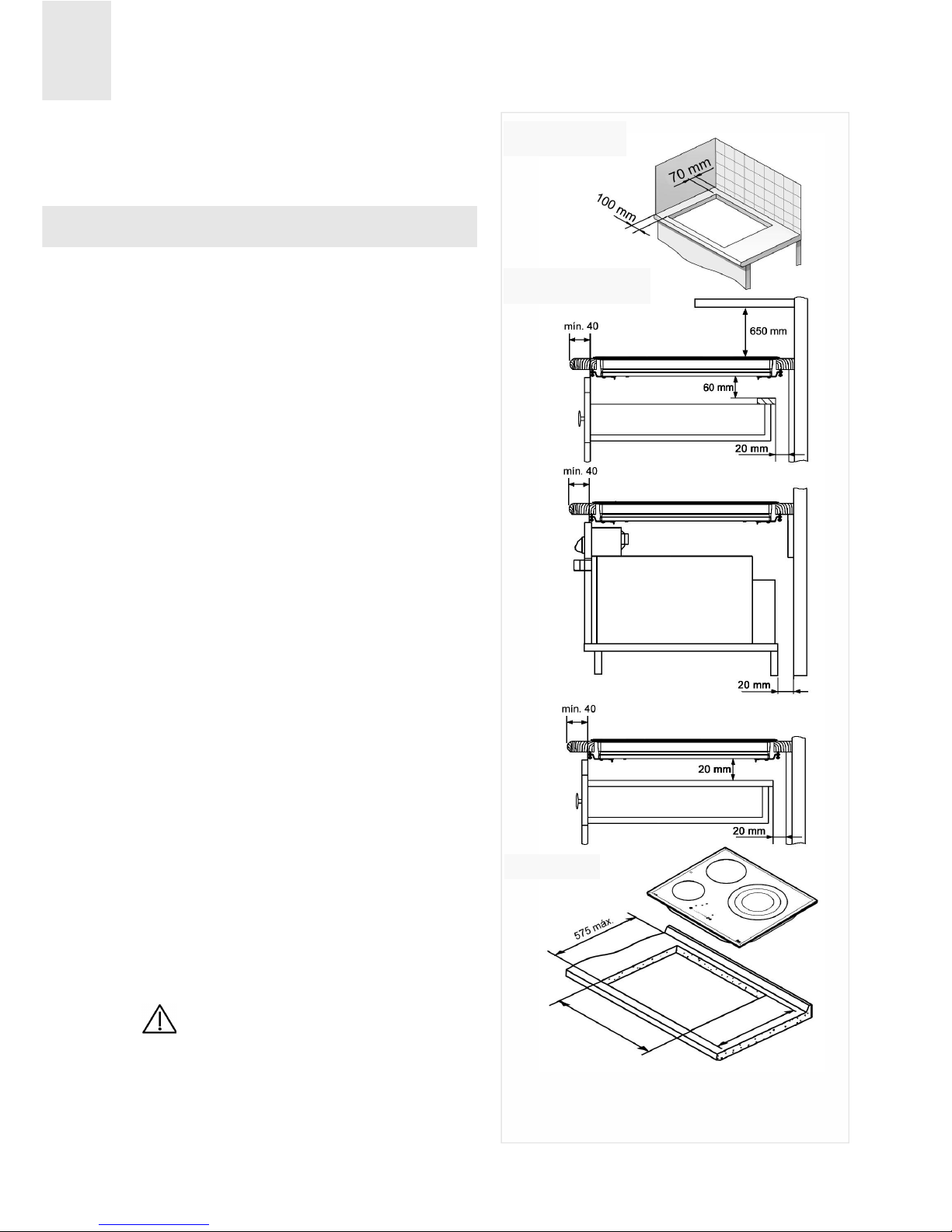
Positioning the hobs
To install these models, an opening with
the dimensions shown in figure 1 should
be cut into the unit's worktop.
The system for fixing the hob is intended
for use with kitchen units with a thickness
of 20, 30 and 40 mm.
The minimum distance between the surface of the hob and the lower part of the kitchen unit or the hood located above the
hob should be 650 mm. If the hood's installation instructions recommend that the
gap is greater than this, you should follow
this advice.
The unit where the hob and oven will be
located should be suitably fixed.
INSTALLATION WITH A CUTLERY
DRAWER OR LOW CUPBOARD
If you wish to have a cupboard or cutlery
drawer beneath the hob, you should install
a separation board between them. The
board should be installed 20 mm below the
bottom of the hob and an empty space of
at least 20 mm should be left at the back of
the cupboard (fig. 1).
This will prevent accidental contact with
the hot surface of the body of the vitroceramic plates underneath the appliance.
(Fig. 1)
Make sure that you do not keep
objects in the drawer that could obstruct the fans of the hob or materials
that may be flammable.
Installation
fig. 1
Minimum distance to walls
Important: minimum
ventilation distances
DRAWER
THERMOVENTI-
LATED OVEN
Radiant element hobs:
DRAWER
Fitting holes
W
L
The dimensions L and W are in the table "Dimensions and characteristics" in the Technical Information section.
GB
13
INSTALLATION WITH A THERMOVENTILATED OVEN UNDER THE HOB
The oven should be installed according to
the corresponding manual.
If installing over a thermoventilated oven,
please remember that this hob has been
certified to work only with TEKA brand
ovens.
An opening of 20 mm should be made in
the back part of the kitchen unit so that
cold air is able to enter (see figure 1).
Warnings:
When hobs are handled before
being installed, care should be taken in
case there is any protruding part or
sharp edge which could cause injury.
When installing units or appliances above the hob, the hob should be
protected by a board so that the glass
cannot be damaged by accidental
blows or heavy weight.
The glues used in manufacturing
the kitchen unit and on the decorative
laminates and on the laminates that are
part of the worktop surface should be
made to tolerate temperatures of up to
100ºC.
TEKA does not assume any responsibility for any malfunction or
damage caused by faulty installation.
PLEASE REMEMBER THAT THE GUARANTEE DOES NOT COVER THE
GLASS IF IT SUFFERS A VIOLENT
BLOW OR IF IT IS USED IMPROPERLY.
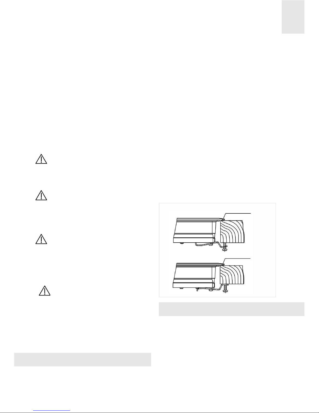
Fixing the hob
When the gap has been properly sized,
the gasket should be put on the lower side
of the glass. Silicone should not be
applied between the glass and the unit
worktop because if it becomes necessary to remove the hob from its position, the glass could break when trying
to detach it.
To fasten the cooking top to the kitchen
unit, use four clips fastened to the existing
openings in the lower part of the body (two
in front and two in back). There are two
possible ways to position the clips, as can
be seen in figure 2.
Depending on the thickness of the worktop,
it is possible to use the self-tapping screws
that are provided as a fastening accessory
by putting them into the clip's round hole.
This hole will be threaded as the screw is
inserted into it. This should be done before
fixing the clip to the worktop.
Connecting the electricity
The electric connection is made using an
omnipolar switch or plug, where accessible, that is suitable for the intensity to be
tolerated and that has a minimum gap of 3
mm between its contacts. This will ensure
disconnection in case of emergency or
when cleaning the hob.
Sealing washer
Sealing washer
fig. 2

The connection should include correct earthing, in compliance with current norms.
If the flexible supply cable fitted to the
appliance ever needs to be changed, it
should be replaced by TEKA's official technical service.
The input cable should not be in contact
either with the body of the hob or with the
body of the oven, if the oven is installed in
the same unit.
GB
14
GB
15
Technical data
Class 3 Hob.
Technical Information
* Power of the induction elements with the Power function activated.
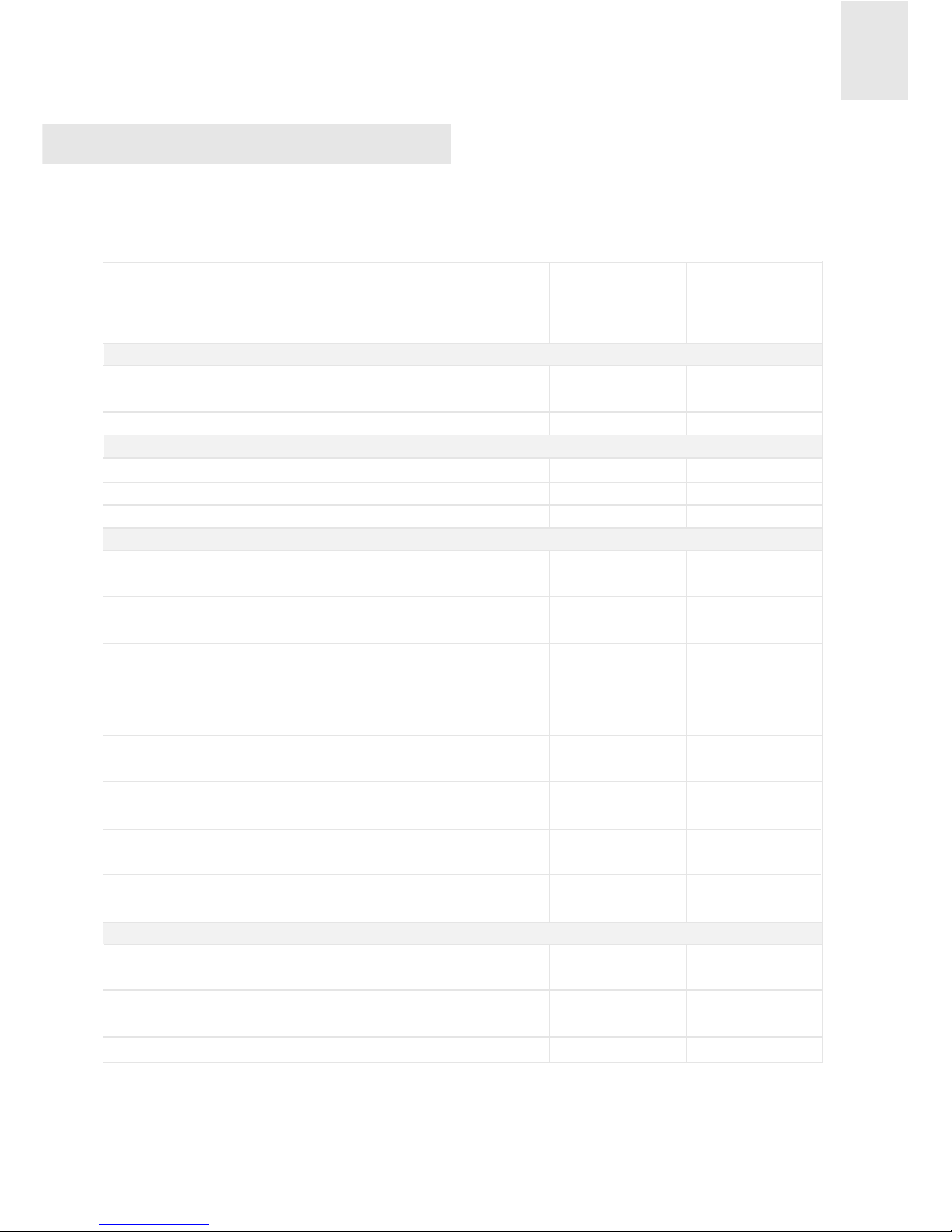
Dimensions and characteristics
Models
Dimensions of the hob
Height (mm)
Length (mm)
Width (mm)
Dimensions for positioning in the kitchen unit
Length (mm) (L)
Width (mm) (W)
Depth (mm)
Configuration
Induction Element
2,300 / 3,200* W
Induction Element
1,400 / 1,800* W
Induction Element
1,850 / 2,500* W
Induction Element
2,400 / 3,200* W
Radiant Element
1,400 / 2,000 W
Radiant Element
1,050 / 1,950 / 2,700 W
Radiant Element
1,800 W
Radiant Element
1,200 W
Electrical data
Nominal power (W)
Maximum for 230 V
Power supply
voltage (V)
Frequency (Hz)
IRS 645
56
600
510
560
490
50
50 / 60
7.200
IRS 635
TRS 645
TRS 635
56
600
510
560
490
50
56
600
510
560
490
61
56
600
510
560
490
61
50 / 60
6.800
50 / 60
6.200
50 / 60
5.700
1
1
2
1
1
1
1
1
2
1
1
1
230
230
230
230
Special requirements before
first use
Before connecting the hob to the electric
mains, check that the voltage and frequency of the mains matches what is
shown on the hob's rating plate, which is
located on the lower part of the hob, and
on the guarantee or, where appropriate,
the technical data sheet supplied, which
should be kept together with this manual
during the useful life of this appliance.
The appliance is not designed to
be used by people (including children)
with reduced physical, mental or sensory abilities. It should also not be used
by people that do not have experience
handling the appliance or who do not
have knowledge of the appliance,
unless they are supervised by a person
who is in charge of their safety.
Children should not be allowed to
play with the appliance.
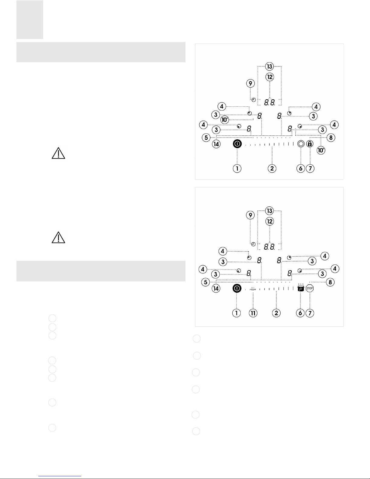
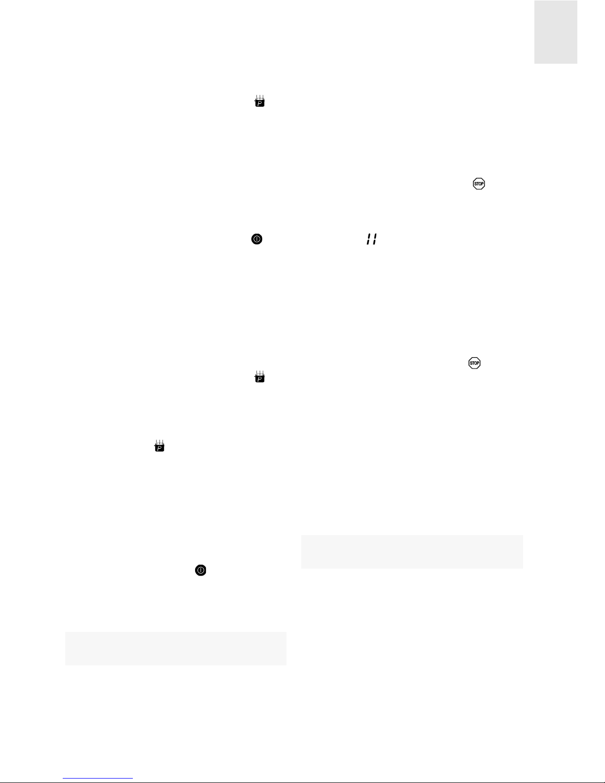
Touch control panel user
instructions
CONTROL PANEL ELEMENTS (see fig. 3
and 4)
On/off sensor button.
Slider cursor to choose the power/time.
SENSOR TO SELECT A HOTPLATE
and power indicators (DIGI-Select
system).
Indicators of the heating element.
Power lights of the Slider cursor.
Power Function sensor button (models
IRS...) or Double/Triple Ring Function
(models TRS...).
Stop Function sensor button (models
IRS...) or Lock Function (models
TRS...).
Stop Function Activated indicator
(models IRS...) or Lock Function indicator (models TRS...).
Indicator symbol of the clock sensors
zone.
Indicator light of the Double/Triple Ring
(models TRS...).
Keep Warm Function sensor button
(models IRS...).
INDICATOR SYMBOL OF THE CLOCK
SENSORS and indicator of selected
time (DIGI-Select system).
Indicator light of the induction element
with timer.
Decimal point in power indicators.
GB
16
Use and Maintenance
1
2
3
4
5
6
8
7
10
11
12
13
14
9
fig. 3
fig. 4
Models TRS...
Models IRS...

GB
17
- Shines (on): Chosen induction element
(ready to be used).
- Doesn't shine (off): Induction element
locked (cannot be used).
NOTE: * Only visible when appliance is
operating.
Actions are carried out using the sensor
buttons marked on the control panel.
It is not necessary put pressure on the
glass; by simply touching the sensor button with your finger you will activate the
desired function.
The touch cursor can be used to adjust the
power levels (1-9) and to choose the time
(1-99) by sliding your finger over it. By sliding your finger to the right, the value will
increase, while sliding it to the left will
cause the value to decrease.
It is also possible to directly select the desired value by touching the area of the
touch cursor with your finger.
Each action is confirmed with a beep.
These hobs have the DIGI-Select
system: the selection of each plate and the
clock is made touching OVER THE
POWER INDICATOR DIGIT (3) AND THE
INDICATOR OF SELECTED TIME
DIGITS (12).
TURNING ON THE APPLIANCE
1 Touch the on sensor button (1) for at
least one second.
The touch control panel is activated and a
0 appears on all the power indicators (3).
The decimal point (14) flashes to indicate
that no cooking zone has been selected at
that time. If a cooking zone is hot, the
corresponding indicator will show an H and
a 0 alternately.
In IRS... models, if the Lock Function is
activated, the indicators in the cooking
zones will have an L. If there is a residual
heat on the cooking zones, the corresponding indicator will have an Land an H alter-
nately.
The next action must be taken within 20
seconds; otherwise, the touch control
panel will automatically turn off. If you
have chosen a heating element at a power
level of 0 and you don't change the value,
the heating element will no longer be
selected after 10 seconds.
When the touch control panel is activated,
it can be disconnected at any time by touching sensor (1), even if it has been
locked (see the section "Locking the sensor buttons of the hob"). Sensor button
(1) is always able to disconnect the
touch control panel.
ACTIVATING THE HEATING ELEMENTS
Once the touch control panel has been
activated by using sensor button (1),
you can turn on the chosen heating elements.
1 Choose the heating element by using the
corresponding indicator (3), in other
words, touching with the finger OVER
THE DIGIT. If the heating element is hot,
the corresponding indicator will go from
showing H to level 0.
2 Use the slider cursor (2) to choose the
power level, from between 0 and 9. By
doing so, the heating element will
remain activated.
Whenever the heating element is selected,
i.e. with the decimal point on, it is possible
to change its power level. If, after 10

seconds you have not chosen any operation, the heating element will no longer be
selected.
TURNING OFF A HEATING ELEMENT
The heating element may be turned off by
decreasing its power level to 0.
When a heating element is turned off, an H
will appear in the corresponding power
indicator instead, if the glass surface is hot
in the corresponding cooking zone, which
means that there is a risk of burns. When
the temperature has decreased, the indicator will turn off (if the hob is disconnected) or, if the hob is connected, the indicator will have a 0.
TURNING OFF ALL OF THE HEATING
ELEMENTS
It is possible to disconnect all of the heating
elements at the same time by suing the
on/off sensor button (1). All of the indicators of the heating elements will turn off.
The power of the heating elements can be
adjusted to nine different levels.
Locking the sensor buttons
of the hob
LOCK FUNCTION
(models TRS...)
You can use the Lock Function to lock the
rest of the sensor buttons, except the
on/off sensor button (1), in order to prevent the unit from being tampered with.
This is a useful safety function when there
are children in the home.
To activate this function, touch the sensor
button (7) for at least two seconds.
Afterwards, the indicator light (8) will go on
to indicate that the control panel is locked.
To deactivate the function, just touch the
sensor button (7) again.
If you turn off the appliance using the
on/off sensor button (1), at the same
time that the lock is activated, the appliance will continue to be locked the next time
it is turned on.
SAFETY FUNCTION
(Models IRS...)
The safety function can be activated after
connecting the hob as long as no heating
element is currently functioning and no
timer is selected.
To do so, follow the following steps:
1 Touch the Power sensor button (6)
and the sensor button of the front right
heating element (3) at the same time.
2 Immediately afterward, touch the sensor
button of the front right heating element
(3) again.
An L (from the work Locked) will appear in
the indicators; although, the indicators
may also show an H if they are still hot.
This should be done within 10 seconds
without touching another sensor button
other than those indicated during this time;
otherwise, the lock function will not be activated.
The control panel will remain locked, even
after the control panel has been disconnected using the on/off sensor button
(1) or when restarting after there has been
a power cut, as long as the user does not
unlock it.
Unlocking to cook
To unlock the control and use the applian-
GB
18
GB
19
ce, follow these steps:
1 Touch the Power sensor button (6)
and the sensor button of the front right
heating element (3) at the same time.
The L will disappear from the indicators
and a 0 with a flashing decimal point (14)
will appear, or an H will appear if the
corresponding heating element is hot, and
the hob will be ready to be used for cooking. When the control panel is disconnected using the on/off sensor button (1),
the safety function will reactive and will
appear again the next time the touch control panel is activated.
Cancelling the safety function
The safety function can be deactivated
permanently by following these steps:
1 Touch the Power sensor button (6)
and the sensor button of the front right
heating element (3) at the same time.
2 Immediately afterward, touch the Power
sensor button (6).
For the operation to be carried out, no
other sensor button should be touched in
the following 10 seconds. If the operation
is not carried out correctly, the touch control panel will remain locked and will turn
off after 20 seconds.
When the on/off sensor (1), is used to
reactivate the control panel after cancelling the safety function, the hob will be
ready to be used for cooking.
Stop Function
(models IRS...)
By using this function, it is possible to
make a pause during the cooking process.
If the timer function is also activated, it will
also be paused.
Activating the Stop function
1 The cookware is located on the cooking
zones, which are working at a certain
level.
2 Touch the Stop sensor button (7) for
one second. The function will be paused.
The symbol will appear in the indicators
of the heating elements, and the error
messages, residual heat, fast heat-up or
lack of cookware indicators, will also
disappear until the function has been
deactivated.
Deactivating the Stop function
1 Touch the Stop sensor button (7) and
then touch any other sensor button
within 10 seconds.
The heating element will go back to how it
was before the Stop function was activated.
The second sensor button must be touched within 10 seconds; otherwise, the
hob will disconnect. If cooking has not
been restarted 10 minutes after the pause,
the appliance will turn off.
Double or Triple Circuit
hotplates (models TRS...)
Double and triple circuit heating elements
make it possible to use the inner ring or,
also, the outer ring(s), depending on the
size of the cookware.
CONNECTING / TURNING ON THE
DOUBLE AND TRIPLE CIRCUIT HEATING ELEMENTS
1 Choose the desired power level (from 1
to 9) using the cursor.
2 Touch the double ring sensor button
(6) to activate the second circuit. Indicator light (10) will turn on, which indicates
that the outer ring is activated.
3 In model TRS 635, if you want to activa-
te the third ring after turning the second
ring on, the touch sensor button (6)
again. After doing so, the second indicator light will turn on.
DISCONNECTING / TURNING OFF THE
DOUBLE CIRCUIT
1 Touch the double ring sensor button
(6). The indicator light (10) will turn off
and the outer ring will be disconnected.
DISCONNECTING / TURNING OFF THE
TRIPLE CIRCUIT (MODEL TRX 635)
1 Touch the sensor button (6). The
second indicator light (10) will turn off
and the third ring will be disconnected.
2 Touch the sensor button (6) again.
The first indicator light (10) and the
second ring will be disconnected. Only
the first circuit will be activated.
Energy supplied according to
the power level chosen
Please remember that the heating
elements adjust the energy supplied
according to the size and type (material) of
the cookware being used. Smaller cookware will receive less energy than larger
cookware.
Cookware detection
(models IRS…)
The induction cooking zones have an
incorporated cookware detector. This will
prevent the heating element from working
if there is no cookware placed on it or if the
cookware is inadequate.
The power indicator will show the symbol
meaning that "there is no cookware" if
no cookware is detected when the zone is
on or if the cookware is inadequate.
If the cookware is taken off of the cooking
zone while the zone is functioning, the
heating element will automatically stop
supplying energy and the "there is no
cookware" symbol will go on. When the
cookware is once again placed on the cooking zone, energy will once again be supplied at the power level that was chosen.
The cookware detection time is 10 minutes. If no cookware is placed on the zone
during this time, or if the cookware is
inadequate, the cooking zone will deactivate. The power indicator will show the
symbol "there is no cookware" or 0.
After use, disconnect the cooking
zone by using the touch control panel.
Otherwise, an undesired operation
could occur in the cooking zone if a
piece of cookware is accidentally placed on the cooking zone during the
following 10 minutes. Avoid possible
accidents!
Recovery Function
(models IRS…)
If the touch control panel has been turned
off by mistake, the Recovery Function
makes it possible to quickly recover all of
the settings made. These settings include
the power levels, the timer of the heating
elements, as well as the Power and HeatUp functions.
After having disconnected the control
panel using the on/off sensor button
GB
20
GB
21
(1), you will have six seconds to turn on
the hob again. After doing so, to recover
the settings lost, touch the Stop sensor
button (7) before another six seconds
pass.
This function will only work if at least one
heating element is active, regardless of
the Lock function.
The activation of the Recovery Function
will be confirmed by a beep.
Heat-up function
(Automatic start of cooking)
This function will help you when cooking,
since it is not necessary to be there at the
same time. The touch control panel preprogrammes the chosen heating element
to the maximum power level and then
lowers it to the desired power level, chosen
by you, after a certain amount of time. (See
table 1)
TURNING ON THE FAST HEAT-UP
FUNCTION
1 Use the corresponding indicator (3) to
activate the desired heating element.
2 Using the Slider cursor (2), slide your fin-
ger up to power level 9 and then touch
the sensor button corresponding to level
9 again. A flashing A will appear in the
indicator.
The power level decreases to the desired
continuous power level (for example, 6)
within the 15 seconds following the activation of the fast heat-up function by means
of the slider cursor (2). The indicator will
flash alternately between 6 and A.
Example:
You want to cook at power level 6 on an
induction element and you want to quickly
heat up the contents of the cookware at the
beginning.
Choose power 9, touch the slider cursor (2)
and an Awill appear, then use the slide cur-
sor (2) to lower the power level to 6. The
system will keep the heating element at
power level 9(maximum) for 120 seconds,
flashing alternately between 6 and A; after
that time, the system will automatically
lower the power level to 6.
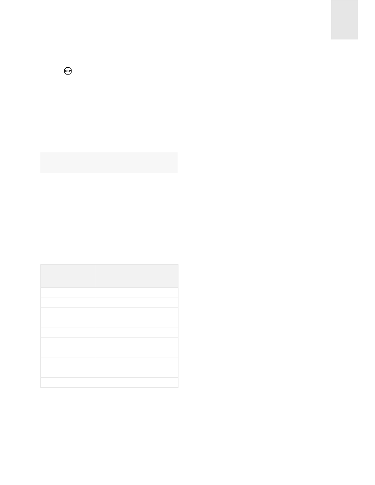
MODIFYING THE POWER LEVEL
DURING THE FAST HEAT-UP
1 The chosen heating element must be
activated. The corresponding decimal
point must be on (14).
2 Change the power level using slider cur-
sor (2).
When increasing the power level using the
slider cursor (2), the system takes into
account the time passed up until that point.
Example:
You are cooking on a heating element and
you have chosen power level 1 (48
Table 1
0
48
144
228
312
408
120
168
216
- - -
0
1
2
3
4
5
6
7
8
9
Level
selected
Duration of Heat-Up
(in seconds)

seconds of fast heat-up) and after 30
seconds you change to power level 4 (312
seconds). The remaining automatic boost
time will be 282 seconds (312 seconds
minus 30 seconds).
The fast heat-up function will stop if the
cookware is taken off the heating element. If the cookware is once again placed on the heating element (10 minutes), the fast heat-up function will restart where it left off.
It is not possible to activate the fast heatup function on the heating elements if the
Power function is activated.
DISCONNECTING THE FAST HEAT-UP
FUNCTION
Once 10 seconds have passed after the
fast heat-up function has been activated:
1 Choose the heating element. The
corresponding decimal point must be on
(14).
2 Touch the slider cursor (2) to a lower
level.
The fast heat-up function will be automatically deactivated and the heating element
will stay on at a constant power level.
Keep warm function
(models IRS…)
By using this function, it is possible to keep
the food warm that is inside cookware placed on a cooking zone.
1 There is cookware on one of the heating
elements at a previously chosen power
level.
2 Touch the sensor (11) and the
symbol will appear in the indicator.
To disconnect this function, just change
the power levels after selecting the heating
element. This function has a maximum
operation time after which the hob will turn
disconnect.
Power Function
(only models IRS…)
It is possible to concentrate additional
power in the induction cooking zones (see
values indicated with an * in the Introduction section) by using the Power function.
1 Choose the desired cooking zone by
using the corresponding sensor button
(3).
2 Touch the Power sensor button (6).
The power level indicator will show the
symbol P.
The Power function has a maximum duration of 10 minutes. After this time, the
power level will automatically adjust to
power level 9.
Each side of the cooker has an induction
generator that works with a maximum
power of 3,600 watts. Therefore, the
Power function cannot be used at the
same time on two induction elements that
are on the same side. In other words, if the
Power function is activated on an induction
element on the left side, the Power function can only be activated on another
induction element that is on the right side.
Once the Power function has been activated on one induction element, the other
induction element on the same side may
use the remaining power, up to a total of
3,600 watts. If its power level is too high,
the touch control panel will automatically
decrease it.
Afterward, the induction element will conti-
GB
22

GB
23
nue operating at power level 9. The function may also disconnect automatically if
the cooking zone temperature is very high.
If the cookware is taken off of the cooking
zone while the Power concentration function is activated, the function will remain
active and the time will continue to pass.
The Power function can also be activated
without placing cookware on the cooking
zone, but the cooking element will not
supply energy until cookware has been
placed on the cooking zone.
Safety disconnection
MAXIMUM OPERATION TIME
If one or various heating elements are
accidentally left on, they will be disconnected automatically after a certain amount of
time has passed after the last action using
the element. (See table 2)
When the "safety disconnection" has occurred, the residual heat indicator H of the
corresponding heating element will appear
in the power indicator if there is a risk of
burn. Otherwise, a 0 will be shown.
SAFETY IN CASE OF COVERED SENSOR BUTTONS
The touch control panel has a function that
makes it so the appliance automatically
detects when there is an object (cookware,
rag or spilled liquids) covering the panel
sensor buttons. This makes it possible to
prevent the object from activating or deactivating a heating element without you realising it.
When the touch control panel disconnects
the appliance for safety reasons, it begins
to beep and it shows an error message
until the object covering the control panel
is removed.
If the touch control panel is in stand-by
mode, it will not detect the presence of an
object on it; nonetheless, to be able to activate the control panel, it is necessary to
remove the object on the control panel
beforehand.
Timer function
This feature enables you to do your cooking while you yourself are not present: the
timed heating element will turn off automatically when the time you have chosen
elapses.
Around the indicator of the chosen time
there are four or three indicator lights (13)
that indicate which of the heating elements
is timed. For example, if you time the
upper left heating element, the light over
the indicator will turn on, on the left.
If the timer is not being used with any of
the heating elements, the clock can be
used as a chronometer that counts backwards (see section "Using the clock as a
Table 2
0
6
6
5
5
4
1,5
1,5
1,5
1,5
10 minutes, readjusts to 9
0
1
2
3
4
5
6
7
8
9
P
Power level
selected
MAXIMUM
OPERATION TIME
(in hours)
 Loading...