


INSTALLATION AND MAINTENANCE MANUAL
CERAMIC HOBS
ANLEITUNG FÜR EINBAU UND INSTANDHALTUNG
GLASKERAMIK-KOCHFELDER
MANUEL D’INSTALLATION ET D’ENTRETIEN
CERAMIC HOBS
IINSTRUKCJA OBS£UGI I MONTA¯U
P£YTY CERAMICZNE
VTN DC – VT CM – VT DUAL.1 – VTC B – VTC DC
TR 640 – TR 620 – VT TC 60.3 – VR 622 – TT 620
VT CM INOX HALOGEN – TT 600 – TT 630 – TC 620
TB 600 – TT 640 – TR 600 – TR 735 AB – TM 620
TR 641 – TM 601

Contents / Inhalt / Table des Matières / Spis treœci
GB
INTRODUCTION
User Guide
INSTALLATION
Positioning the hobs
Fixing the hob
Connecting the electricity
Positioning the oven
Ceramic hobs with controls:
Joining the hob to the oven
or control panel
Model VT DUAL. 1:
Connecting the gas
Gas conversion
TECHNICAL INFORMATION
Dimensions and power
Technical details
USE AND MAINTENANCE
Requirements before first use
Touch control user instructions:
Double or Triple circuit hotplate
Locking the hob’s sensor
Safety disconnection
Heat-up function
Timer function
The clock as countdown timer
Power surges
Ceramic hobs with controls
instructions
Model VT DUAL. 1:
Anti-accidental turn system
on gas controls
Igniting the burners
Suggestions on using the
burners effectively
Cleaning and care the burners
Mantaining the VT DUAL.1
Advice on using the glass ceramic
hotplates effectively
Cleaning and care
If something doesn’t work
Page 4
13
14
14
15
16
16
16
16
17
17
18
19
19
21
22
22
22
24
25
26
26
27
29
30
31
32
32
32
33
33
34
34
35
37
DE
EINFÜHRUNG
Hinweise zum Gebrauch
EINBAU
Einbauort für die Kochfelder
Verankerung des Kochfelds
Elektrischer Anschluss
Einbauort für den Ofen
Glasmeramik-kochfelder mit
bedienelementen:
Anschluss des Kochfeldes an den
Backofen oder an das Bedienfeld
Modell VT DUAL.1:
Gasanschluss
Umstellung auf andere Gasart
TECHNISCHE INFORMATION
Abmessungen und Leistungsmerkmale
Technische Daten
GEBRAUCH UND INSTANDHALTUNG
Voraussetzungen für die
Inbetriebnahme
Gebrauchsanweisung für die
Berührungssensoren:
Zweikreis oder
Dreikreis-Kochzonen
Verriegelung der Berührungssensoren für das Kochfeld
Sicherheits-Abschaltung
Elektronische Ankochautomatik
Timerfunktion
Verwendung der Uhr als
Stoppuhr für Countdown
Überspannungen im Stromnetz
Funktionsweise der
Glaskeramik-Kochzonen mit
bedienelementen
Model VT DUAL. 1:
Schutz gegen versehentliches
Drehen der Gasregler
Anzünden der Gasbrenner
Tipps für den korrekten Gebrauch
der Brenner
Reinigung und Pflege der Brenner
Instandhaltung VT DUAL.1
Tipps für den korrekten Gebrauch
der VT-Kochzonen
Reinigung und Pflege
Seite 4
39
40
40
41
42
42
43
43
44
44
44
46
46
48
49
49
49
51
52
53
53
54
57
58
59
60
60
60
61
62
62
62
63
2
Im Störungsfall
66

FR
Strona 4
959696979898989999
100
101
101
103
104
104
106
107
107
108
109
111
111
112
113
113
113
114
114
115
115
115
118
PRÉSENTATION
Guide d’utilisation
Page 4
68
PL
OPIS URZ¥DZENIA
Przed pierwszym u¿yciem
INSTALLATION
Logement des tables de cuisson
Fixation des tables de cuisson
Branchement électrique
Logement du four
Vitroceramique a commande:
Raccordement de la table de
cuisson au four ou au bandeau
de commandes
Modèle VT DUAL.1:
Raccordement au gaz
Adaptation du gaz
INFORMATIONS TECHNIQUES
Dimensions et puissances
Données techniques
UTILISATION ET ENTRETIEN
Conditions de mise en service
Instructions d’utilisation de
la commande sensitive:
Plaques à double et triple foyer
Blocage des Touches sensitives
de la table de cuisson
Déconnexion de sécurité
Coup de cuisson
Fonction minuteur
L’Horloge en tant que chronométre
de compte à rebours
Surtensions sur la ligne
Fonctionnement des plaques
vitrocéramiques a commande
Modèle VT DUAL.1:
Système de blocage de
commandes de gaz
Allumage des brûleurs
Recommandations pour une
bonne utilisation des brûleurs
Nettoyage et entretien des
brûleurs
Entretien de la VT DUAL.1
Recommandations pour une
bonne utilisation des plaques VT
Nettoyage et stockage
69
INSTALACJA
69
Monta¿
70
Monta¿ p³yty
71
Po³¹czenie elektryczne
71
Monta¿ piekarnika
71
Pod³¹czenie p³yty do piekarnika
Model VT DUAL. 1:
71
72
72
73
74
74
76
77
77
77
79
80
81
81
82
85
86
86
88
88
88
89
89
90
90
90
Pod³¹czenie do instalacji gazowej
Zmiana ciœnienia i/lub rodzaju gazu
INFORMACJE TECHNICZNE
Tabela wymiarów i danych technicznych
Dane techniczne
OBS£UGA URZ¥DZENIA
Sensorowy panel steruj¹cy
Potrójne/podwójne pole grzejne
Blokada nastawieñ
Wy³¹cznik bezpieczeñstwa
Funkcja szybkiego zagotowania
Timer
Minutnik
Zabezpieczenie przed przegrzaniem
P³yty ceramiczne ze sterowaniem
pokrêt³ami
Model VT DUAL. 1:
Zabezpieczenie przed przypadkowym
w³¹czeniem palników gazowych
Zapalenie palników
Zalecenia dotycz¹ce u¿ywania
palników gazowych
Czyszczenie i pielêgnacja palników
Konserwacja p³yty VT DUAL.1
Wskazówki i zalecenia dotycz¹ce
korzystania z pól grzejnych
Czyszczenie i konserwacja
Przed wezwaniem serwisu
Si quelque chose ne fonctionne pas
93
3

Introduction / Einführung / Présentation / Opis urz¹dzenia
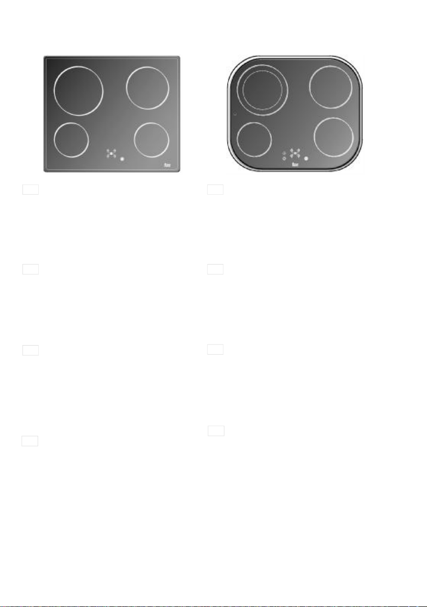
1
3
2
4
5
Model VTN DC
GB
1 1,200 watt hotplate.
2 1,800 watt hotplate.
3 700/2,100 watt double circuit hotplate.
4 1,800 watt hotplate.
5 Residual heat indicator lights.
* Maximum electric power: 6,900 watts.
Modell VTN DC
DE
1 Kochzone 1200 W
2 Kochzone 1800 W
3 Zweikreis-Kochzone mit 700/2100 W
4 Kochzone 1800 W
5 Kontrollleuchten zur Restwärme-Anzeige
* Maximale elektrische Leistung: 6900 W
Modèle VTN DC
FR
1 Plaque de 1.200 Watts.
2 Plaque de 1.800 Watts.
3 Plaque à double foyer de 700/2.100 Watts.
4 Plaque de 1.800 Watts.
5 Témoins de chaleur résiduelle.
* Puissance électrique maximale: 6.900 Watts.
Model VTN DC
PL
1 Pole grzejne o mocy 1.200 W
2 Pole grzejne o mocy 1.800 W
3 Pole grzejne podwójne o mocy 700 / 2.100 W
4 Pole grzejne o mocy 1.800 W
5 Wska¿niki zalegania ciep³a
* Maksymalny pobór mocy 6.900 W
1
3
Model VT CM
GB
1 1,200 watt hotplate.
2 1,800 watt hotplate.
3 1,800 watt hotplate.
4 1,200 watt hotplate.
5 Residual heat indicator lights.
* Maximum electric power: 6,000 watts.
Modell VT CM
DE
1 Kochzone 1200 W
2 Kochzone 1800 W
3 Kochzone 1800 W
4 Kochzone 1200 W
5 Kontrollleuchten zur Restwärme-Anzeige
* Maximale elektrische Leistung: 6000 W
Modèle VT CM
FR
1 Plaque de 1.200 Watts.
2 Plaque de 1.800 Watts.
3 Plaque de 1.800 Watts.
4 Plaque de 1.200 Watts.
5 Témoins de chaleur résiduelle.
* Puissance électrique maximale: 6.000
Watts.
Model VT CM
PL
1 Pole grzejne o mocy 1.200 W
2 Pole grzejne o mocy 1.800 W
3 Pole grzejne o mocy 1.800 W
4 Pole grzejne o mocy 1.200 W
5 Wska¿niki zalegania ciep³a
* Maksymalny pobór mocy 6.000 W
2
4
5
4

5
1
2
5
3
Model VT DUAL.1
GB
1 700/2,100 watt double circuit hotplate.
2 Semi-rapid burner 1,500 Kcal/h -1.75 kW.
3 1200 watt hotplate.
4 Rapid burner 2,580 Kcal/h -3 kW.
5 Grids.
6 Residual heat indicator lights.
* Maximum electric power: 3,300 watts.
* Maximum calorific power: 4,080 Kcal/h - 4.75
kW/h.
DE
Modell VT DUAL.1
1 Zweikreis-Kochzone mit 700/2100 W
2 Mittel-Brenner mit 1500 kcal/h - 1,75 kW
3 Kochzone 1200 W
4 Stark-Brenner mit 2580 kcal/h - 3 kW
5 Stellroste
6 Kontrollleuchten zur Restwärme-Anzeige
* Maximale elektrische Leistung: 3300 W
* Maximale Wärmeleistung: 4080 Kcal/h -
4,75 kW/h
Modèle VT DUAL.1
FR
1 Plaque à double foyer de 700/2.100 Watts.
2 Brûleur semi-rapide de 1.500 Kcal/h -
1,75 kW.
3 Plaque de 1.200 Watts.
4 Brûleur rapide de 2.580 Kcal/h - 3 kW.
5 Grilles.
6 Témoins de chaleur résiduelle.
* Puissance électrique maximale: 3.300
Watts.
* Puissance calorifique maximale: 4.080
Kcal/h - 4,75 kW.
6
4
1
3
Model VT CM INOX HALOGEN
GB
1 1,200 watt hotplate.
2 1,800 watt halogen hotplate.
3 1,800 watt hotplate.
4 1,200 watt hotplate.
5 Residual heat indicator lights.
* Maximum electric power: 6,000 watts.
Modell VT CM
DE
1 Kochzone 1200 W
2 Halogen-Kochzone 1800 W
3 Kochzone 1800 W
4 Kochzone 1200 W
5 Kontrollleuchten zur Restwärme-Anzeige
* Maximale elektrische Leistung: 6000 W
Modèle VT CM
FR
1 Plaque de 1.200 Watts.
2 Plaque halogène de 1.800 Watts.
3 Plaque de 1.800 Watts.
4 Plaque de 1.200 Watts.
5 Témoins de chaleur résiduelle.
* Puissance électrique maximale: 6.000
Watts.
PL
Model VT CM INOX HALOGEN
1 Pole grzejne o mocy 1.200 W
2 Pole grzejne o mocy 1.800 W
3 Pole grzejne o mocy 1.800 W
4 Pole grzejne o mocy 1.200 W
5 Wska¿niki zalegania ciep³a
* Maksymalny pobór mocy 6.000 W
2
4
5
Model VT DUAL.1
PL
1 Pole grzejne podwójne o mocy 700 / 2.100 W
2 Palnik gazowy o mocy 1.750 W
3 Pole grzejne o mocy 1.200 W
4 Palnik gazowy o mocy 3.000 W
5 Ruszty
6 Wska¿niki zalegania ciep³a
* Maksymalny pobór mocy 3.300 W
* Maksymalna moc grzejna (gaz) 4.750 W/h
5

1
2
1
2
3
5
Model VTC DC
GB
1 1,200 watt hotplate.
2 1,800 watt hotplate.
3 700/2,100 watt double circuit hotplate.
4 1,800 watt hotplate.
5 Residual heat indicator lights.
* Maximum electric power: 6,900 watts.
Modell VTC DC
DE
1 Kochzone 1200 W
2 Kochzone 1800 W
3 Zweikreis-Kochzone mit 700/2100 W
4 Kochzone 1800 W
5 Kontrollleuchten zur Restwärme-Anzeige
* Maximale elektrische Leistung: 6900 W
Modèle VTC DC
FR
1 Plaque de 1.200 Watts.
2 Plaque de 1.800 Watts.
3 Plaque à double foyer de 700/2.100 Watts.
4 Plaque de 1.800 Watts.
5 Témoins de chaleur résiduelle.
* Puissance électrique maximale: 6.900
Watts.
4
3
Model VTC B
GB
1 1,200 watt hotplate.
2 1,800 watt hotplate.
3 2,100 watt hotplate.
4 1,200 watt hotplate.
5 Residual heat indicator lights.
* Maximum electric power: 6,300 watts.
Modell VTC B
DE
1 Kochzone 1200 W
2 Kochzone 1800 W
3 Kochzone 2100 W
4 Kochzone 1200 W
5 Kontrollleuchten zur Restwärme-Anzeige
* Maximale elektrische Leistung: 6300 W
Modèle VTC B
FR
1 Plaque de 1.200 Watts.
2 Plaque de 1.800 Watts.
3 Plaque de 2.100 Watts.
4 Plaque de 1.200 Watts.
5 Témoins de chaleur résiduelle.
* Puissance électrique maximale: 6.300
Watts.
5
4
Model VTC DC
PL
1 Pole grzejne o mocy 1.200 W
2 Pole grzejne o mocy 1.800 W
3 Pole grzejne podwójne o mocy 700 / 2.100 W
4 Pole grzejne o mocy 1.800 W
5 Wska¿niki zalegania ciep³a
* Maksymalny pobór mocy 6.900 W
6
PL
Model VTC B
1 Pole grzejne o mocy 1.200 W
2 Pole grzejne o mocy 1.800 W
3 Pole grzejne o mocy 2.100 W
4 Pole grzejne o mocy 1.200 W
5 Wska¿niki zalegania ciep³a
* Maksymalny pobór mocy 6.300 W

1
1 Plaque à double foyer de 1.400/2.000 Watts.
* Puissance électrique maximale: 6.500 Watts.
2
1
2
3
5
Model VR 622
GB
1 1,500 watt hotplate.
2 1,400/2,000 watt double circuit hotplate.
3 700/2,100 watt double circuit hotplate.
4 1,500 watt hotplate.
5 Residual heat indicator lights.
* Maximum electric power: 7,100 watts.
Modell VR 622
DE
1 Kochzone 1500 W
2 Zweikreis-Kochzone mit 1400/2000 W
3 Zweikreis-Kochzone mit 700/2100 W
4 Kochzone 1500 W
5 Kontrollleuchten zur Restwärme-Anzeige
* Maximale elektrische Leistung: 7100 W
Modèle VR 622
FR
1 Plaque de 1.500 Watts.
2 Plaque à double foyer de 1.400/2.000 Watts.
3 Plaque à double foyer de 700/2.100 Watts.
4 Plaque de 1.500 Watts.
5 Témoins de chaleur résiduelle.
* Puissance électrique maximale: 7.100 watts.
Model VR 622
PL
1 Pole grzejne o mocy 1.500 W
2 1.400/2.000 watt double circuit hotplate.
3 Pole grzejne podwójne o mocy 700 / 2.100 W
4 Pole grzejne o mocy 1.500 W
5 Wska¿niki zalegania ciep³a
* Maksymalny pobór mocy 7.100 W
4
3
Model TT 620
GB
1 1,400/2,000 watt double circuit hotplate.
2 1,800 watt hotplate.
3 1,200 watt hotplate.
4 1,500 watt hotplate.
* Residual heat indicator. ( H )
* Maximum electric power: 6,500 watts.
Modell TT 620
DE
1 Zweikreis-Kochzone mit 1400/2000 W
2 Kochzone 1800 W
3 Kochzone 1200 W
4 Kochzone 1500 W
* Restwärme-Anzeige ( H )
* Maximale elektrische Leistung: 6500 W
Modèle TT 620
FR
2 Plaque de 1.800 Watts.
3 Plaque de 1.200 Watts.
4 Plaque de 1.500 Watts.
* Témoin de chaleur résiduelle. ( H )
Model TT 620
PL
1 1.400/2.000 watt double circuit hotplate.
2 Pole grzejne o mocy 1.800 W
3 Pole grzejne o mocy 1.200 W
4 Pole grzejne o mocy 1.500 W
* Wska¿niki zalegania ciep³a (H)
* Maksymalny pobór mocy 6.500 W
4
7

1
2
1
2
Model VT TC 60.3
GB
3
4
1 1,200 watt hotplate.
2 700/1,700 watt double circuit hotplate.
3 1,400/2,000 watt double circuit hotplate.
4 1,200 watt hotplate.
* Residual heat indicator. ( H )
* Maximum electric power: 6,100 watts.
Modell VT TC 60.3
DE
1 Kochzone 1200 W
2 Zweikreis-Kochzone mit 700/1700 W
3 Zweikreis-Kochzone mit 1400/2000 W
4 Kochzone 1200 W
* Restwärme-Anzeige ( H )
* Maximale elektrische Leistung: 6100 W
Modèle VT TC 60.3
FR
1 Plaque de 1.200 Watts.
2 Plaque à double foyer de 700/1.700 Watts.
3 Plaque à double foyer de 1.400/2.000 Watts.
4 Plaque de 1.200 Watts.
* Témoin de chaleur résiduelle. ( H )
* Puissance électrique maximale: 6.100
Watts.
4
Model TR 620
GB
3
1 700/2,100 watt double circuit hotplate.
2 1,800 watt hotplate.
3 1,500 watt hotplate.
4 1,200 watt hotplate.
* Residual heat indicator. ( H )
* Maximum electric power: 6,600 watts.
Modell TR 620
DE
1 Zweikreis-Kochzone mit 700/2100 W
2 Kochzone 1800 W
3 Kochzone 1500 W
4 Kochzone 1200 W
* Restwärme-Anzeige ( H )
* Maximale elektrische Leistung: 6600 W
Modèle TR 620
FR
1 Plaque à double foyer de 700/2.100 Watts.
2 Plaque de 1.800 Watts.
3 Plaque de 1.500 Watts.
4 Plaque de 1.200 Watts.
* Témoin de chaleur résiduelle. ( H )
* Puissance électrique maximale: 6.600
Watts.
Model VT TC 60.3
PL
1 Pole grzejne o mocy 1.200 W
2 Pole grzejne podwójne o mocy 700 / 1.700 W
3 Pole grzejne podwójne o mocy 1.400 / 2.000 W
4 Pole grzejne o mocy 1.200 W
* Wska¿niki zalegania ciep³a (H)
* Maksymalny pobór mocy 6.100 W
8
Model TR 620
PL
1 Pole grzejne podwójne o mocy 700 / 2.100 W
2 Pole grzejne o mocy 1.800 W
3 Pole grzejne o mocy 1.500 W
4 Pole grzejne o mocy 1.200 W
* Wska¿niki zalegania ciep³a (H)
* Maksymalny pobór mocy 6.600 W

1
2
1
2
3
GB
Model TT 630
1 1,800 watt hotplate.
2 1,500/2,400 watt double circuit hotplate.
3 1,200 watt hotplate.
* Residual heat indicator. ( H )
* Maximum electric power: 5,400 watts.
DE
Modelle TT 630
1 Kochzone 1800 W
2 Zweikreis-Kochzone mit 1500/2400 W
3 Kochzone 1200 W
* Restwärme-Anzeige ( H )
* Maximale elektrische Leistung: 5400 W
FR
Modèle TT 630
1 Plaque de 1.800 Watts.
2 Plaque à double foyer de 1.500/2.400
Watts.
3 Plaque de 1.200 Watts.
* Témoin de chaleur résiduelle. ( H )
* Puissance électrique maximale: 5.400
Watts.
Model TT 630
PL
1 Pole grzejne o mocy 1.800 W
2 Pole grzejne podwójne o mocy 1.500 /
2.400 W
3 Pole grzejne o mocy 1.200 W
* Wska¿niki zalegania ciep³a (H)
* Maksymalny pobór mocy 5.400 W
3
Models TR 640 and TT 640
GB
1 700/1,700 watt double circuit hotplate.
2 1,800/2,700 (or 1,500/2,400 Watts, according
to the model) watt double circuit hotplate.
3 1,200 watt hotplate.
* Residual heat indicator. ( H )
* Maximum electric power: 5,300 (or 5,600)
watts.
Modelle TR 640 und TT 640
DE
1 Zweikreis-Kochzone mit 700/1700 W
2 Zweikreis-Kochzone mit 1800/2700 (oder
1.500/2.400 W, je nach Modell) W
3 Kochzone 1200 W
* Restwärme-Anzeige ( H )
* Maximale elektrische Leistung: 5300 (oder
5,600) W
Modèles TR 640 et TT 640
FR
1 Plaque à double foyer de 700/1.700 Watts.
2 Plaque à double foyer de 1.800/2.700
(1.500/2.400 Watts, selon le modèle) Watts.
3 Plaque de 1.200 Watts.
* Témoin de chaleur résiduelle. ( H )
* Puissance électrique maximale: 5.300 (ou
5,600) Watts.
PL
Modele TR 640 and TT 640
1 Pole grzejne podwójne o mocy 700 / 1.700 W
2 Pole grzejne podwójne o mocy 1.800 / 2.700
W (lub 1.800 / 2.700 W – w zale¿noœci od
modelu)
3 Pole grzejne o mocy 1.200 W
* Wska¿nik zalegania ciep³a (H)
* Maksymalny pobór mocy 5.300 (lub 5.600) W
9
1
2
1
2
3
GB
Model TT 600, TR 600 and TB 600
1 2,100 watt hotplate.
2 1,800 watt hotplate.
3 1,200 watt hotplate.
4 1,200 watt hotplate.
* Residual heat indicator. ( H )
* Maximum electric power: 6,300 watts.
DE
Modell TT 600, TR 600 und TB 600
1 Kochzone 2100 W
2 Kochzone 1800 W
3 Kochzone 1200 W
4 Kochzone 1200 W
* Restwärme-Anzeige ( H )
* Maximale elektrische Leistung: 6300 W
Modèle TT 600, TR 600 et TB 600
FR
1 Plaque de 2.100 Watts.
2 Plaque de 1.800 Watts.
3 Plaque de 1.200 Watts.
4 Plaque de 1.200 Watts.
* Témoin de chaleur résiduelle. ( H )
* Puissance électrique maximale: 6.300
Watts.
Model TT 600,TR 600 andTB 600
PL
1 Pole grzejne o mocy 2.100 W
2 Pole grzejne o mocy 1.800 W
3 Pole grzejne o mocy 1.200 W
4 Pole grzejne o mocy 1.200 W
* Wska¿niki zalegania ciep³a (H)
* Maksymalny pobór mocy 6.300 W
4
GB
3
Model TC 620
4
1 1,400/2,000 watt double circuit hotplate.
2 1,800 watt hotplate.
3 1,200 watt hotplate.
4 1,500 watt hotplate.
* Residual heat indicator. ( H )
* Maximum electric power: 6,500 watts.
DE
Modelle TC 620
1 Zweikreis-Kochzone mit 1400/2000 W
2 Kochzone 1800 W
3 Kochzone 1200 W
4 Kochzone 1500 W
* Restwärme-Anzeige ( H )
* Maximale elektrische Leistung: 6500 W
FR
Modèle TC 620
1 Plaque à double foyer de 1.400/2.000 Watts.
2 Plaque de 1.800 Watts.
3 Plaque de 1.200 Watts.
4 Plaque de 1.500 Watts.
* Témoin de chaleur résiduelle. ( H )
* Puissance électrique maximale: 6.500 Watts.
Model TC 620
PL
1 Pole grzejne podwójne o mocy 1.400 / 2.000 W
2 Pole grzejne o mocy 1.800 W
3 Pole grzejne o mocy 1.200 W
4 Pole grzejne o mocy 1.500 W
* Wska¿niki zalegania ciep³a (H)
* Maksymalny pobór mocy 6.500 W
10

1
1
2
2
3
GB
Model TR 735 AB
1 1,800 watt hotplate.
2 1050 / 1,950 / 2,700 watt hotplate.
3 1,200 watt hotplate.
* Residual heat indicator. ( H )
* Maximum electric power: 5,700 watts.
DE
Modell TR 735 AB
1 Kochzone 1800 W
2 Kochzone 1050 / 1950 / 2700 W
3 Kochzone 1200 W
* Restwärme-Anzeige ( H )
* Maximale elektrische Leistung: 5700 W
FR
Modèle TR 735 AB
1 Plaque de 1800 Watts.
2 Plaque de 1.050 / 1.950 / 2.700 Watts.
3 Plaque de 1.200 Watts.
* Témoin de chaleur résiduelle. ( H )
* Puissance électrique maximale: 5.700
Watts.
PL
Model TR 735 AB
1 Pole grzejne o mocy 1.800 W
2 Pole grzejne potrójne o mocy
1.050 / 1.950 / 2.700 W
3 Pole grzejne o mocy 1.200 W
* Wska¿niki zalegania ciep³a (H)
* Maksymalny pobór mocy 5.700 W
4
Model TM 620
GB
3
1 700/2,100 watt double circuit hotplate.
2 1,800 watt hotplate.
3 1,500 watt hotplate.
4 1,200 watt hotplate.
* Residual heat indicator. ( H )
* Maximum electric power: 6,600 watts.
DE
Modell TM 620
1 Zweikreis-Kochzone mit 700/2100 W
2 Kochzone 1800 W
3 Kochzone 1500 W
4 Kochzone 1200 W
* Restwärme-Anzeige ( H )
* Maximale elektrische Leistung: 6600 W
Modèle TM 620
FR
1 Plaque à double foyer de 700/2.100 Watts.
2 Plaque de 1.800 Watts.
3 Plaque de 1.500 Watts.
4 Plaque de 1.200 Watts.
* Témoin de chaleur résiduelle. ( H )
* Puissance électrique maximale: 6.600
Watts.
Model TM 620
PL
1 Pole grzejne podwójne o mocy 700 / 2.100 W
2 Pole grzejne o mocy 1.800 W
3 Pole grzejne o mocy 1.500 W
4 Pole grzejne o mocy 1.200 W
* Wska¿niki zalegania ciep³a (H)
* Maksymalny pobór mocy 6.600 W
11

1
2
1
2
4
GB
Model TM 601
3
1 2,100 watt hotplate.
2 1,800 watt hotplate.
3 1,200 watt hotplate.
4 1,200 watt hotplate.
* Residual heat indicator. ( H )
* Maximum electric power: 6,300 watts.
DE
Modell TM 601
1 Kochzone 2100 W
2 Kochzone 1800 W
3 Kochzone 1200 W
4 Kochzone 1200 W
* Restwärme-Anzeige ( H )
* Maximale elektrische Leistung: 6300 W
Modèle TM 601
FR
1 Plaque de 2.100 Watts.
2 Plaque de 1.800 Watts.
3 Plaque de 1.200 Watts.
4 Plaque de 1.200 Watts.
* Témoin de chaleur résiduelle. ( H )
* Puissance électrique maximale: 6.300
Watts.
4
GB
Model TR 641
3
1 1,400/2,000 watt double circuit hotplate.
2 1,800 watt hotplate.
3 1,200 watt hotplate.
4 1,200 watt hotplate.
* Residual heat indicator. ( H )
* Maximum electric power: 6,200 watts.
DE
Modell TR 641
1 Zweikreis-Kochzone mit 1400/2000 W
2 Kochzone 1800 W
3 Kochzone 1200 W
4 Kochzone 1200 W
* Restwärme-Anzeige ( H )
* Maximale elektrische Leistung: 6200 W
Modèle TR 641
FR
1 Plaque à double foyer de 1.400/2.000 Watts.
2 Plaque de 1.800 Watts.
3 Plaque de 1.200 Watts.
4 Plaque de 1.200 Watts.
* Témoin de chaleur résiduelle. ( H )
* Puissance électrique maximale: 6.200
Watts.
Model TM 601
PL
1 Pole grzejne o mocy 2.100 W
2 Pole grzejne o mocy 1.800 W
3 Pole grzejne o mocy 1.200 W
4 Pole grzejne o mocy 1.200 W
* Wska¿niki zalegania ciep³a (H)
* Maksymalny pobór mocy 6.300 W
12
Model TR 641
PL
1 Pole grzejne podwójne o mocy 1.400 / 2.100 W
2 Pole grzejne o mocy 1.800 W
3 Pole grzejne o mocy 1.200 W
4 Pole grzejne o mocy 1.200 W
* Wska¿niki zalegania ciep³a (H)
* Maksymalny pobór mocy 6.200 W

GB
Guide to Using the Instructions Booklet
Dear customer,
We are delighted that you have put your
trust in us.
We are confident that the new hob that
you have purchased will fully satisfy your
needs.
This modern, functional and practical
model has been manufactured using topquality materials that have undergone
strict quality controls throughout the manufacturing process.
Before installing and using it, we would
ask that you read this Manual carefully
and follow the instructions closely, as this
will guarantee better results when using
the appliance.
Keep this Instruction Manual in a safe place
so that you can refer to it easily and thus
abide by the guarantee conditions.
In order to benefit from this Guarantee, it is
essential that you submit the purchase receipt together with the Guarantee certificate.
You should keep the Guarantee
Certificate or, where relevant, the technical datasheet, together with the Instruction Manual for the duration of the
useful life of the appliance. It has important technical information about the
appliance.
Safety instructions
Before first use, you should carefully read
the installation and connection instructions.
These hob models may be installed in the
same kitchen furniture units as TEKA
brand ovens.
For your safety, installation should be carried out by an authorised technician and
should comply with existing installation
standards. Likewise, any internal work on
the hob should only be done by TEKA’s
technical staff, including the change of the
flexible supply cable of the appliance.
Please note:
When the hotplates are in operation or have recently been in operation,
some areas will be hot and can burn.
Children should be kept well away.
If the glass ceramic breaks or
cracks, the hob should immediately be
disconnected from the electric current
in order to avoid the risk of electric
shock.
When the halogen heating elements are in operation, you should not
look directly at them in case damage is
caused.
13

GB
Installation
Important
INSTALLATION AND SETUP SHOULD
BE CARRIED OUT BY AN AUTHORISED
TECHNICIAN IN LINE WITH CURRENT
INSTALLATION STANDARDS.
Positioning the hobs
Depending on the model to be installed, an
opening with the dimensions shown in figure 2 will be cut into the unit’s worktop.
The system for fixing the hob is intended
for use with kitchen units with a thickness
of 20, 30 and 40 mm. In the packaging of
the models VTN DC and TC 620, there is
a template included that is for use in sizing
the space for these glass ceramic hob models.
See the fiting hole’s dimensions for each
model on the “dimensions and characteristics” table of this manual. The minimum
distance between the surface supporting
the cooking pans and the lower part of the
kitchen unit or the hood located above the
hob should be 650 mm. If the hood’s installation instructions recommend that the
gap is greater than this, you should follow
this advice.
The hobs described in this manual can
only be installed with Teka ovens. Models
with no control knobs are only to be installed with Teka ovens and/or Teka control
panels.
The unit where the hob and oven will be located will be suitably fixed.
Minimum distances
to walls
Minimum ventilation
distances
minimun 40 mm
minimun 40 mm
minimun 40 mm
fig. 1
OVEN
OVEN
INSTALLATION WITH A CUTLERY DRAWER OR LOW CUPBOARD (TOUCH
CONTROL MODELS)
If you wish to have a cupboard or cutlery
drawer beneath the hob, you should install
14
a panel to separate them. This will prevent
accidental contact with the hot surface of
the body of the appliance.
The board should be installed 20 mm
below the bottom of the hob and an empty

GB
Fitting holes
m
i
x
a
m
fig. 2
protected by a board so that the glass
cannot be damaged by accidental
blows or heavy weights.
5
7
5
n
u
The glues used in manufacturing
the kitchen unit and in the adhesive on
the decorative laminate of the worktop
surface should be made to tolerate temperatures of up to 100ºC.
5
7
5
n
u
m
i
x
a
m
L
VTN DC and TC 620
Rest of the models The dimensions L and W are
shown in the table "Dimensions and characteristics" of the Technical Information section.
W
space of at least 20 mm should be left at
the back of the cupboard. As an alternative to this type of panel, you can install a
detachable protective cover to the bottom
of the hob, which can be obtained from our
Technical Services using the reference indicated.
Protective cover
Ref. Models
81253177
81253176
TT 600, TB 600, TR 640, TT
640, TR 620, TT 630, TR 600,
TR 735 AB, TM 620, TR 641
and TM 601
VT TC 60.3, TT 620 and
TC 620
TEKA assumes no responsibility
for any malfunction or damage caused
by faulty installation.
PLEASE REMEMBER THAT THE GUARANTEE DOES NOT COVER THE
GLASS IF IT SUFFERS A VIOLENT
BLOW OR IF IT IS USED IMPROPERLY.
Fixing the hob
(see figs. 3 and 4)
When the gap has been properly sized,
the sealing washer should be put on the
lower part of the hob. With models VR 622,
TR 620, TR 640, TT 640, TT 600, TB 600,
TR 600, TT 630, TR 735 AB, TM 620, TR
641 and TM 601 the washer will be stuck
to the lower face of the glass.
Silicone should not be applied between
the glass and the unit worktop because
if it becomes necessary to remove the
hob from its position, the glass could
break when trying to detach it.
Position the clips as shown in the diagram,
fastening them to the openings in the lower
part of the body using the screws provided.
When hobs are handled before
being installed, care should be taken in
case there is any protruding part or
sharp edge which could cause injury.
When installing units or applian-
ces above the hob, the hob should be
For worktop thicknesses of 30 mm. or less,
use the self-tapping screws (M5) that are
provided as a fastening accessory - put
them into the clip’s round hole. This hole
will be threaded as the screw is inserted
into it, and this should be done before fixing the clip to the worktop.
15

GB
Sealing joint
20/30 mm
Self-tapping screw for 20
and 30 mm thick worktops
Sealing joint
40 mm
20/30 mm
Self-tapping screw for 20
and 30 mm thick worktops
40 mm
The connection should include correct earthing, in compliance with current norms.
If the flexible supply cable fitted to the VT CM
hob model ever needs to be changed, it
should be replaced by TEKA’s official service.
The input cable should not be in contact either with the body of the hob or with the
body of the oven, if the oven is installed in
the same unit.
fig. 3
Positioning the oven
See the corresponding manual.
The oven’s placement should be as shown
in your instruction manual, and the manual
should also be referred to when connecting the electricity. Before accessing the inside of the appliance, the appliance should
be disconnected from the power.
fig. 4
The clips and the sealing joint are provided, and can be found in the packaging.
Connecting the electricity
Before connecting the hob to the electric
mains, check that the voltage and frequency of the mains matches what is
shown on the hob’s rating plate, which is
located lower down, and on the guarantee
certificate or, where appropriate, the technical datasheet supplied, which should be
kept together with this manual.
The electric connection is made via an omnipolar switch or plug where accessible,
which is suitable for the intensity to be tolerated and which has a minimum gap of 3
mm between its contacts, which will ensure disconnection in case of emergency or
when cleaning the hob.
16
Ceramic hobs with controls
Joining the hob to the oven
or the control panel
For this purpose, four cardan telescopic
shafts are included with the hob. (See fig.
5). The way to join them is as follows:
1 Turn off the electricity.
2 Detach the cardan telescopic shafts by
pressing on the retention clip (A), where
it says PUSH, with a slim screwdriver,
and pull the extension out a few centi-
metres.
3 Remove the four pins from the ends (B).
4 Put the oven part-way into its space, ta-
king care not to drag the cardan telescopic shafts coming from the hob, and
leaving enough space to put in the other
ends of the telescopic shafts into the
shafts in the rear part of the control
panel, and then replace the pins. (See
fig. 5)

GB
fig. 5
Rear view of the Control Panel:
fig. 6
Flexible supply cable
Connector
Protective box for electrical assembly
Retention clips
Pins
5 To make the electric connection betwe-
en the two appliances, attach the hob’s
connector to oven’s connector.
6 Complete the definitive positioning of
the oven, ensuring that the cardan telescopic shafts are firmly in position and
that the telescopic pipes are well-aligned when inserted so that sliding is
quite simple.
7 Position the controls on the front of the
oven.
8 To operate the control knobs, they first
have to be pressed in, and then turned
in order to release the safety device.
If the cardan telescopic shafts are too
short, extensions can be added (not provided, but available as an accessory).
These are added by pressing, and they
are fixed by the cover that is included.
Model VT DUAL.1
Connecting the gas
Connecting the hob to the gas mains
should be done in compliance with the current installation standards and/or regulations.
Ventilation slots should also be made at
the site in compliance with current norms.
The hob is provided with a threaded connection 1/2” in diameter, in line with ISO
228-1. A Ø 10/12 mm. copper pipe is provided as an accessory for welding the gas
inlet pipe.
Whenever the gas connection nut is removed, its joint should be changed.
In order that the hob is not damaged by
tightening the nut on the gas connection
17

GB
pipe, a maximum torque of 300 Kgf * cm
should be applied.
The injectors required for each gas type
are shown in table 1.
When the gas connection has been made,
the installation should be checked to ensure that it is completely sealed. If the check
is done using air, care should be taken that
the test pressure is no more than 200
g./cm2. Where air is not available, soapy
water should be applied to ensure that
there are no leaks in the connections. Tes-
ting should never be done using a
flame.
When the hob has been installed, check
that the burner minimums are properly adjusted. To do this, light the burners and
check that they do not go out if you switch
quickly from the maximum to the minimum.
Gas conversion
Important!
Any alteration that is to be made to the
appliance to convert it to a different
type of gas should only be carried out
by a qualified technician.
Information for Technical Assis-
tance: whenever the type of gas or the ap-
pliance’s pressure is changed, the new regulation plate should be placed on top of
the old one so that the new features can
be seen after the change.
To replace the injectors, follow these instructions:
1 Remove the grids and upper parts of the
burner so that the injector can be seen.
2 Using a number 7 pipe spanner, remove
the injectors and replace them with the
new ones. Take care to press the injector
down firmly so that there is no leakage.
3 Replace the grid and burners that were
previously removed.
When the injectors have been changed,
this is how to adjust the minimums:
1 Take the oven or the control panel out so
that you can access the gas taps.
2 Turn the burners on to their minimum.
3 Use a slim, grooved screwdriver to turn
the screw located to the right or in the
centre of the gas tap’s shaft (the flame
increases when you turn to the left and
decreases when you turn to the right).
4 When properly adjusted, check that the
flame does not go out when you turn the
knob quickly from maximum to minimum.
TEKA INDUSTRIAL, S.A. assumes no
responsibility for any hob malfunction if the
gas conversion or the adjustment of the
burners’ minimums has not been carried
out by TEKA’s official personnel.
The tasks involved in conversion are:
* Replace the injectors.
* Adjust the taps’ minimums.
Table 1
Burner Family
Rapid 116 Y 116 Y 85
Semi-rapid 97 Z 97 Z 66
Ø injector expressed in 1/100 mm.
18
Second Third
Group H Group E+ Group 3+

GB
Technical information
Dimensions and Characteristics
TR 640
(L)
TT 640
560 560 580 580
490 490 492 492
Models
Hob dimensions
Height (mm) 65 65 67 65
Length (mm) 600 600 600 600
Width (mm) 510 510 510 510
Dimensions of the placement in the unit
Length (mm)
Width (mm)
Depth (mm) 61 61 63 60
Configuration
Double radiant hotplate
1800/2700 W circuit
Triple radiant hotplate
1050/1950/2700W circuit
Double radiant hotplate
700/2100W circuit
Double radiant hotplate
700/1700W circuit 1 1
Double radiant hotplate
1400/2000W circuit
2100W radiant hotplate
1800W halogen
radiant hotplate
1800W radiant hotplate
1200W radiant hotplate
1500W radiant hotplate
Electrics
Nominal Power
(W) for 230 V* 5.600 6.600 6.500 6.100
Supply
voltage (V)
Frequency (Hz) 50-60 50-60 50-60 50-60
* For voltages other than 230 V please consult the rating plate
(W)
TC
TR 620
620
TM 620
65
590
510
570
492
60
1
1
1
1 1 1 2
1
1
6.500
50-60
TT VT TC
620 60.3
1
1 1
1 1
1 1
SEE THE APPLIANCE’S RATING PLATE
TR 735
AB
65
700
540
560
490
61
1
1
1
5.700
50-60
TT 600
TR 600
TB 600
TM 601
65
600
510
560
490
61
1
1
2
6.300
50-60
VT CM
TT
INOX
630
HALO-
GEN
65
85
600
600
510
510
560
580
490
492
61
60
1
1
1
1
1
2
5.400 6.000
50-60
50-60
19

GB
Models VTN VT VTC B VT CM VR VTC
DC DUAL.1 622 DC
Hob dimensions
Height (mm) 120 163 120 85 120 120
Length (mm) 590 600 600 600 600 600
Width (mm) 510 510 510 510 510 510
Dimensions of the placement in the unit
Length (mm)
Width (mm)
(L)
(W)
570 580 580 580 580 580
492 492 492 492 492 492
Depth (mm) 115 117 115 60 115 115
Configuration
Double radiant hotplate
700/2100W circuit
Double radiant hotplate
1 1 1 1
700/1700W circuit
Double radiant hotplate
1400/2000W circuit
2100W radiant hotplate
1 1
1800W halogen
radiant hotplate
1800W radiant hotplate
1500W radiant hotplate
1200W radiant hotplate
2 1 2 2
2
1 1 2 2 1
3 kW rapid burner 1
1.75 kW semi-rapid 1
burner
Electrics
Nominal Power
(W) for 230 V*
Supply
voltage (V)
6.900 3.300 6.300 6.000 6.700 6.900
SEE THE APPLIANCE’S RATING PLATE
Frequency (Hz) 50-60 50-60 50-60 50-60 50-60 50-60
Gas
Power
Maximum (kW) 4,75
* For voltages other than 230 V please consult the appliance’s rating plate
TR
641
65
600
510
560
490
61
1
1
2
6.200
50-60
20

GB
Technical details
CHARACTERISTICS COMMON TO ALL
MODELS
The supply voltage and frequency will be
as shown on the rating plate.
CHARACTERISTICS OF THE VT DUAL.1
clear, a window opened, or an effective
mechical ventilation system device,
such as a hood, installed.
The intense and prolonged use
of the appliance may call for complementary ventilation, such as opening a
window, or more efficient ventilation
such as increasing the power of the
mechanical ventilation if this exists.
Warnings:
a) Before installation, make sure that the
local supply conditions (the gas type and
pressure) are compatible with the appliance’s setup.
b) The setup conditions for this appliance
are written on the label (or the rating
plate).
c) This appliance should not be connected
to a device for removing combustion products. It should be installed and connected
in compliance with the current installation
standards. Special attention should be paid
to the regulations applying to ventilation.
A gas cooking appliance produces heat and moisture at the site where
it is installed. The kitchen should be
provided with suitable ventilation: natural ventilation sources should be kept
Table 3
Burner
Nominal Calorific Consumption KW
Nominal Consumption* G-20 (Nm3/h)
G-25 (Nm3/h)
G-30 (Kg/h)
G-31 (Kg/h)
Reduced calorific consumption
Performance
* Consumption over Gross Calorific Value (H )
s
You should keep the Guarantee Certificate or, where relevant, the
technical datasheet, together with
the Instruction Manual for the duration of the useful life of the appliance.
It has important technical information
about the appliance.
Class 3 hob.
Table 2
3
>52
Category
II2E+3+
II2H3+
I3+
II2H3+
Semi-rapid
1,75
0,17
0,19
0,13
0,13
0,40
>52
Country
France
United Kingdom
Greece
Italy
kW
%
mbar
20
25
29
37
Rapid
0,29
0,33
0,22
0,21
0,70
21

GB
Use and Maintenance
Special requirements
before first use
Before connecting the hob to the electric
mains, check that the voltage and frequency of the mains matches what is
shown on the hob’s rating plate, which is
located lower down, and on the guarantee
or, where appropriate, the technical datasheet supplied, which should be kept together with this manual.
The apparatus is not designed to
be used by people (including children)
with reduced physical, mental or sensory abilities. It should also not be used
by people that do not have experience
handling the apparatus or who do not
have knowledge of the apparatus, unless they are supervised by a person
who is in charge of their safety.
Children should not be allowed
to play with the apparatus.
Touch control user
instructions
Model VT TC 60.3
fig. 7
CONTROL ELEMENTS (Figs. 7, 8 and 9)
1
On/off sensor.
2
Hotplate selection sensors.
3
Power and/or residual heat indicators
(also shows that locking is activated on
the models shown if figure 8).
4
“Minus” sensor, reduce power/time.
5
Increase power/time sensor (plus).
6
Select double/triple circuit (double or triple hotplate) sensor.
Select timer/countdown timer sensor
7
(Models TR 640, TC 620, TT 640, TR
735 AB and TR 641).
Clock Indicator (Models TR 640, TC
8
620, TT 640, TR 735 AB and TR 641).
Keylock sensor (except in models
9
shown in figure 8).
22
Models TT 630, TT 600, TB 600,
TC 620, TR 600, TR 735 AB, TR
641 and TM 601
fig. 8

GB
Models TR 640, TT 640, TR 620, TT 620 and TM 620
fig. 9
Light indicating the hotplate's double
10
circuit is on (only next to double circuit
hotplates). In triple circuit hotplates,
there are two indicator lights, one for
each additional circuit.
11
Indicator light for timed hotplate (Models
TR 640, TC 620, TT 640, TR 735 AB and
TR 641).
Keylock indicator light (models shown in
12
figures 7 and 9).
13
Decimal point on indicators:
Light on: Hotplate enabled.
Light off (switched off): Hotplate disabled.
Indicator light for countdown counter.
14
* Only visible when in operation.
The controls are all operated by using the
sensors, each of which has an indicator
associated thereto. There is no need to
apply pressure to the glass on the sensor
you wish to use - the function is activated
simply by touching it with your fingertips.
Each action is confirmed by a beep.
SWITCHING THE APPLIANCE ON
1 Touch the On sensor (1) for at least
one second.
The touch control is activated and a 0 appears on all the power indicators (3) and
the decimal point (13) flashes on and off.
The operation below must be carried out within 10 seconds (20 seconds on the models
TT 600, TT 630, TB 600, TR 600, TC 620,
TR 735 AB, TR 641 and TM 601), or the
touch control will automatically switch off.
SELECTING THE HOTPLATE TO BE
SWITCHED ON
Once the touch control has been enabled
using the sensor (1), the hotplates required can be enabled.
1 Touch the chosen hotplate's sensor (2).
A 0 appears on the corresponding
power indicator (3), and the decimal
point (13) comes on to show that the
hotplate is enabled.
2 Using sensor or (4/5) select the
power you want.
On models TT 600, TT 630, TB
600, TR 600, TC 620, TR 735 AB, TR 641
and TM 601 the sensor has a double
function: to enable the hotplate (first
23

GB
press) and to increase the power (touch
when the hotplate is already switched on).
The power sensor needs to be touched within 5 seconds after choosing the hotplate,
or the hotplate will switch off and will have
to be enabled again.
Sensors and are repetitive, so if
you keep your finger on them, they go up
or down in 0.5-second intervals.
Only one hotplate can be selected at a
time (2), which means that only one decimal point (13) will be lit up.
longer exists, the indicator light will go out
(if the hob is disconnected), or a 0 will
show if the hob is still connected.
Switch the hotplate off before you have finished cooking if you wish to take advantage of the residual heat and thus save
electricity.
Please note: If there is a power cut
while the H is turned on, and then the
power comes straight back on again, the
residual heat indicators will not come
back on even if the cooking surfaces are
still hot. You should bear this in mind.
Please note:
Before operating a hotplate, it needs to
be selected. When you want to use a
hotplate, check that the corresponding
luminous point (13) is lit up.
To turn a hotplate up to full power
quickly: Once the hotplate has been se-
lected, touch sensor (4) once, and the
hotplate will be switched on to full power.
SWITCHING THE HOTPLATE OFF
1 The hotplate must have already been se-
lected. The corresponding decimal point
(13) must be lit.
2 Use sensor (4) to decrease the power
to level 0. The hotplate will automatically
switch off.
To turn it off quickly: By touching sensors and (4/5) simultaneously, the
hotplate will be turned off quickly.
RESIDUAL HEAT INDICATOR
On the hotplate's power indicator, a H will
appear when the surface of the glass in
this area reaches a temperature at which
there is a risk of burning. When this risk no
SWITCHING THE APPLIANCE OFF
The appliance can be switched off at any
time by touching the general on/off sensor
In Standby mode, a H will appear in the
areas that are hot. None of the other hotplate displays will light up.
Double and Triple Circuit
Hotplates (except on TB 600,
TT 600, TR 600 and TM 601)
Double and triple circuit hotplates offer the
option of using either the inside ring or the
outside rings as well, depending on the
size of the pan.
CONNECTING / TURNING ON THE
DOUBLE AND TRIPLE HOTPLATE
1 The corresponding hotplate must be se-
lected - the decimal point (13) must be lit
up.
2 Select the power you want (between 1
and 9) using sensor or (4/5).
3 Touch the double hotplate sensor (6)
to activate the second circuit. When the
pilot (10) comes on, it is in operation.
24

GB
4 On model TR 735 AB, if once the second
circuit is in operation you then wish to
activate the third circuit, touch the sensor (6) once again. Once you have
done this, the second pilot light (10) will
come on.
(12) is lit.
If you use the on / off sensor to turn the ap-
pliance off when locking is activated, the
appliance will still be locked when you turn
the appliance back on again.
Models TT 630, TC 620 and TR 641:
The double circuit may be activated or deactivated by touching the sensor (6) at
any time, providing the hotplate is switched on.
DISCONNECTING / TURNING OFF THE
DOUBLE HOTPLATE
1 The hotplate that you want to disconnect
has to be already activated. The decimal
point (13) must be lit.
2 Touch the double hotplate's sensor
(6). The pilot (10) will go off, and the outside ring will be disconnected.
DISCONNECTING / TURNING OFF THE
TRIPLE HOTPLATE (MODEL TR735 AB)
1 Touch the sensor (6). The first pilot
light (10) will go off, and the third ring will
be disconnected.
2 If you touch the sensor (6) once again
the second pilot light (10) will go off and
the second ring will be disconnected.
Only the first circuit will remain on.
Locking the Hob's Sensors
To avoid the controls being tampered with,
you can block the entire unit, except for
the on/off sensor, using the locking sensor
(9), (except on models TT 600, TB 600,
TT 630, TR 600, TC 620, TR 735 AB, TR
641 and TM 601 - see next section). This
feature is useful as a child-safety device.
When locking is enabled, the pilot light
SAFETY FUNCTION (only models TT
600, TB 600, TR 600, TT 630, TC 620, TR
735 AB, TR 641 and TM 601 )
The safety function can be enabled after
the hob is connected. To do so, touch sensor (1) to enable the touch control. Immediately touch sensor (4) for five seconds. An L (for 'Locked') will appear on
the displays. The touch control will be switched off after a few seconds. If the cooking
area is hot, an L and an H will appear alternately on the corresponding display.
This needs to be done within 5 seconds
after the touch control is activated, with no
sensor other than those indicated being
touched during that time, or the locking will
not be carried out.
The electronic control will remain locked
until the user unlocks it, even after the control is disconnected using the on/off sensor
or when restarting after there has been a
power cut.
Unlocking for cooking (only models
shown in figure 8)
To unlock the control and use it, touch sensor (1) to enable the touch control. Immediately touch, at the same time, the two
sensors to the right or, on models TR
735 AB and TT 630, to the left. The L vanishes from the display and an 0 appears
with the lower point flashing, or a H and an
0 appear alternately if the corresponding
hotplate is hot, and the hob will be ready to
use for cooking. When you disconnect the
control with the on/off sensor (1) the
25

GB
locking function will be reactivated and will
reappear the next time the touch control is
activated.
Cancelling the locking function
Locking can be permanently deactivated
by touching sensor (4) for 5 seconds
immediately after activating the touch control. This should be done within 5 seconds
after activating the touch control with the
on/off sensor (1), and the locking function will be cancelled and the control disconnected. If this is not done properly, the
touch control will remain locked and will
switch off after 20 seconds.
The locking has been deactivated. When
the sensor is reactivated with the on/off
sensor (1), the hob will be ready to be
used for cooking.
Safety disconnection
If one or more hotplates have, in error, not
been switched off, the unit automatically
disconnects after a certain length of time
(see table 4).
Table 4
Power
Selected
1 and 2
3 and 4
5
6, 7, 8 and 9
When this safety disconnection has taken
place, a 0 appears if the temperature on
the surface of the glass is dangerous to
the user, or a H appears if there is, indeed,
a risk of burning.
To use the appliance again, use the on / off
sensor (1) to switch it off, and then
Maximum Operating
Time (In hours)
6
5
4
1,5
switch it back on again.
Heat-up function
(Automatic cooking start)
This feature enables you to set the start
time for cooking. The touch control preprograms the selected hotplate to full
power and then decreases it to the power
you have chosen after a certain length of
time (see table 5).
Table 5
Power
Selected
1
2
3
4
5
6
7
8
9
SWITCHING HEAT-UP FUNCTION ON
1 The hotplate must have already been se-
lected. The corresponding decimal point
must be lit (13).
2 Select power 9 and then touch sensor
. The power light will flash on and off,
alternating between 9and A; now use
sensor to lower it to the constant cooking level you want - 6, for example.
The indicator light flashes alternately
between 6 and A.
e.g.:
You want to cook at power level 6 and
begin with rapid heating. Select power 9,
touch sensor again and the power in-
Start Automatic Cooking
Feature (Time in mins.)
1
3
4,8
6,5
8,5
2,5
3,5
4,5
---
26

GB
dicator will flash on and off, alternating between 9 and A, then decrease it to power 6
using sensor . The system will keep the
hotplate at power 9 (maximum) for 2.5 minutes, flashing on and off alternately between 6 and A, then (after 2.5 mins.) it will
automatically decrease to constant cooking level 6.
MODIFYING THE POWER LEVEL DURING HEAT-UP FUNCTION
1 The hotplate must have already been se-
lected. The corresponding decimal point
must be lit (13).
Timer Function
This feature enables you to do your cooking
while you yourself are not present: The
timed hotplate will switch off automatically
when the time you have chosen elapses.
MODELS TR 640 AND TT 640
On these models you can set the timer on
all hotplates both independently or simultaneously.
Switching on the clock
2 Use sensor or to change the
power level (4/5).
When increasing the power using the
sensor (5) the time that has already
elapsed is taken into account.
e.g.:
You have selected power 1 (1 minute's remote cooking) and after 30 seconds you
change it to 4 (6.5 minutes). The heat-up
time will be 6 minutes (6.30 minus 0.30).
When you use sensor (4) to alter the
power, remote cooking automatically disconnects.
SWITCHING HEAT-UP FUNCTION OFF
When at least 10 seconds have elapsed
since activating remote cooking:
1 The hotplate must have already been se-
lected. The decimal point (13) must be
lit.
2 Touch the sensor (4). The remote co-
oking function is deactivated.
1 The hotplate to be controlled must have
already been selected. The corresponding decimal point (13) must be lit. The
monitoring indicator light (11) that corresponds to the hotplate selected will
come on.
2 Select a power level between 1 and 9 for
the hotplate that has been selected.
3 Touch the clock sensor (7). The indi-
cator (8) shows 00 and a decimal point
will appear (13).
4 Use the or sensors (5/4) to select
the time you wish to set (from 1 to 99 minutes).
The clock will, after just a few seconds,
begin to monitor the time automatically.
You can keep your finger on the or
sensors (5/4) to make the minutes pass
by automatically and choose your selection more quickly.
If you wish to set the timer for another hotplate, the same process should be repeated (steps 1 to 4).
27

GB
Viewing / Changing the programmed
time
To view on the clock indicator (8) the time
left before the hotplate turns off, you only
have to select the hotplate required, both
the decimal point (13) and the control pilot
light (11) which corresponds to the selected hotplate will turn on.
selected hotplate (11) must be on.
2 Touch the clock sensor (7). The deci-
mal point for the clock (13) will come on.
3 Use the sensor (4) to decrease the
time to 00.
Quick switch-off
If you wish to change the time left, follow
the steps below:
1 The hotplate that is to be controlled must
have already been selected. Both the
decimal point (13) and the control pilot
(11) which corresponds to the selected
hotplate must be on.
2 Touch the clock sensor (7). The deci-
mal point (13) for the clock will come on.
3 Use the or sensors (5/4) to alter
the time.
Alternatively you can directly touch the
clock sensor (7) various times until the
control pilot (11) for the hotplate required
comes on. You can then also change the
time, if required, using the sensors or
(5/4).
Disconnecting the clock
When the time that was programmed for
the hotplate elapses, a series of beeps will
sound for at least a minute.
Repeat steps 1 and 2 above.
3 Touch sensors and (5 and 4) si-
multaneously and the clock will be disconnected.
The clock will have been cancelled, but the
hotplate will still be active until you switch
it off.
MODELS TC 620, TR 735 AB AND TR 641
On these models, you can use the clock as
a countdown timer for periods between 1
and 99 minutes, and as a hotplate timer for
times between 1 and 99 minutes. All the
cooking areas can be programmed inde-
pendently and simultaneously.
Timing a hotplate
1 The cooking area to be timed has to be
selected. The corresponding decimal
point (13) must be lit.
2 Select a power level of between 1 and 9
using the or sensors (5-4).
To stop the beeping, touch any sensor.
The hotplate will now be disconnected.
If you wish to stop the clock before the
time programmed has elapsed:
1 The hotplate that is to be controlled must
have already been selected. The decimal point (13) and the pilot light for the
28
3 Touch the clock sensor (7). The deci-
mal point (13) of the time display (8)
(which shows 00) will come on, and it
will flash on and off along with the control display (11) of the corresponding
area.
4 Touch the clock sensor (7) again to
increase the value of the time you wish

GB
to set, or (4) to decrease it (from 1 to
99 minutes). You can keep your finger
on the or sensors (7/4) to make
the minutes pass by automatically to
make your selection more quickly.
The clock will begin to control the time automatically. The control display (11) corresponding to the timed area will remain
lit up.
When the chosen time elapses, the timed
area will switch off and the clock will give a
series of beeps for several seconds. The
time display will show 00and this will flash
on and off, along with the control display
for the area that has disconnected.
Disconnecting the clock
If you wish to stop the clock before the programmed time has elapsed:
1 The hotplate being timed must have al-
ready been selected. The corresponding
decimal point (13) must be lit.
2 Select the clock sensor (7). The deci-
mal point (13) will come on.
3 Use sensor (4) to reduce the time
down to 00. The clock is cancelled but
the hotplate will remain enabled until
you switch it off.
Quick switch-off
If the cooking area that has been switched
off is hot, its display will show an H, otherwise it will show a 0. Touch any sensor to
switch off the beeping signal.
When more than one cooking area is
being timed simultaneously, the time display will show the cooking time remaining
in the area to disconnect first by default. If
you wish to check the cooking time remaining in another area, touch the area's selection sensor. For a few seconds the display will show the remaining cooking time
for that area.
Changing the programmed time
The time set can be changed later on if
you wish.
1 The hotplate being timed must have al-
ready been selected. The corresponding
decimal point (13) must be lit.
2 Touch the clock sensor (7). The deci-
mal point (13) will come on.
3 Use the or sensors (7/4) to alter
the time.
1 The hotplate being timed must have al-
ready been selected. The corresponding
decimal point (13) must be lit.
2 Select the countdown timer sensor
(7). The corresponding decimal point
(13) must be lit.
3 Touching the and sensors (7 and
4) at the same time cancels the remaining time.
You can also switch the hotplate being
timed off without the programmed time having elapsed. In this case, the timer will
switch off too.
The clock as a
countdown timer
MODELS TT 640 AND TR 640
Switching on the counter
The countdown timer can be activated at
any time, even when timing another cooking area.
29

GB
1 Touch the clock sensor (7) various
times, until the pilot light (14) underneath the clock indicators (8) lights up.
2 Before using any hotplate, touch the
clock sensor (7). All the control displays (11) are switched off.
2 Use the or sensors (5/4) to alter
the time.
The countdown timer is activated, even
though the hob is disconnected, until it has
counted down the time required, or until
you turn it off.
Switching off the counter
If you wish to stop the countdown timer before the programmed time has elapsed:
1 Touch the clock sensor (7) various
times, until the pilot light (14) underneath the clock indicators (8) is lit.
2 Use sensor (4) to reduce the time to
00. The clock is cancelled.
Quick switch-off
1 Touch the countdown timer sensor
(7) various times, until the pilot light (14)
underneath the clock indicators (8) is lit.
2 Touch sensors and (5 and 4) si-
multaneously and the counter will be
disconnected.
MODELS TC 620, TR 735 AB AND TR 641
Whenever the clock is not being used in
conjunction with a cooking area, it can be
used as a countdown timer. To do this, you
use the clock without selecting a hotplate.
3 Use the or sensors to input the
time.
When the programmed time elapses, a se-
ries of beeps will sound for several se-
conds. To switch these beeps off, touch
the sensor (7).
Switching off the counter
If you wish to stop the countdown timer be-
fore the programmed time has elapsed:
1 Select the countdown timer sensor
(7). The decimal point (13) will come on.
2 Use sensor (4) to reduce the time to
00. The clock is cancelled.
Quick switch-off
1 Select the countdown timer sensor
(7). The decimal point (13) will come on.
2 Touch the sensors or (7/4) simul-
taneously and the clock will be disconnected.
Always keep the area for contro-
lling the cooking areas empty and dry.
When any problem concerning the
controls arises that is not covered in
this manual, you should disconnect the
appliance and contact TEKA's technical
service.
Switching on the counter
When the appliance is switched off.
1 Touch the On sensor (1).
30
Power surges
When the touch control system undergoes
a power surge of the type which may occur
within electricity supply networks, the hotplates will disconnect and a continuous, in-
 Loading...