

Teka TR150 Series, TR300 Series, TR300-120, TR150-277, TR300-277 Installation Instructions Manual
Installation Instructions
TOOLS
NEEDED:
TR300 SERIES™
120V Magnetic Transformer
Waterproof Wire Connectors
Mounting Hardware
Warning
Hot Surface
INSTRUCTIONS PERTAINING TO
A RISK OF FIRE, OR INJURY TO
PERSONS IMPORTANT SAFETY
INSTRUCTIONS
WARNING - To reduce the risk of FIRE OR INJURY TO PERSONS:
Turn off/unplug and allow to cool before replacing lamp.
Lamp gets HOT quickly! Contact only switch/plug when
Do not touch hot lens, guard, or enclosure (see diagram/
Do no touch the lamp at any time. Use a soft cloth. Oil
Do not operate the luminaire fitting with a missing or
Please refer to the low voltage design
guide at www.tekaillumination.com/
lvguide before installation for proper
Lighted lamp is HOT!
turning on.
Keep lamp away from materials that may burn.
picture).
from skin may damage lamp.
damaged shield.
SAVE THESE INSTRUCTIONS
wire selection.
High Voltage
By Others
IMPORTANT SAFETY INFORMATION - READ, FOLLOW, AND SAVE ALL SAFETY
AND INSTALLATION INSTRUCTIONS
• Product must be installed by a qualified person in a manner
consistent with its intended use and in compliance with the
National Electrical Code, Canadian Electrical Code, and all Local
and Provincial Codes.
• Follow product label information and instructions.
• Qualified Personnel must perform all servicing or relamping of
this product.
• Before wiring to power supply and during servicing or relamping,
turn off power at fuse or circuit breaker before service.
• The use of accessory equipment not recommended by the
manufacturer or installed contrary to instructions may cause an
unsafe condition. The use of damaged components may cause
an unsafe condition and void product warranty.
IMPORTANT LISTINGS AND CERTIFICATIONS
· Suitable for wet locations
• Do not block light emanating from product in whole or part,
as this may cause an unsafe condition.
• Never operate the fixture with missing or damaged lens.
Lens must be cleaned on regular basis.
• Entire fixture may become extremely hot. Do not touch hot
lens or fixture body. Do not touch the lamp at any time. Use
a clean, dry, soft cloth to handle the lamp. Oil from skin may
damage the lamp and cause it to rupture.
• Replace lamp only with correct wattage and type of lamp
marked on fixture label.
• All gaskets, o-rings and sealing surfaces must be kept clean
during installation and service; failure to do this may cause an
unsafe condition and void product warranty.
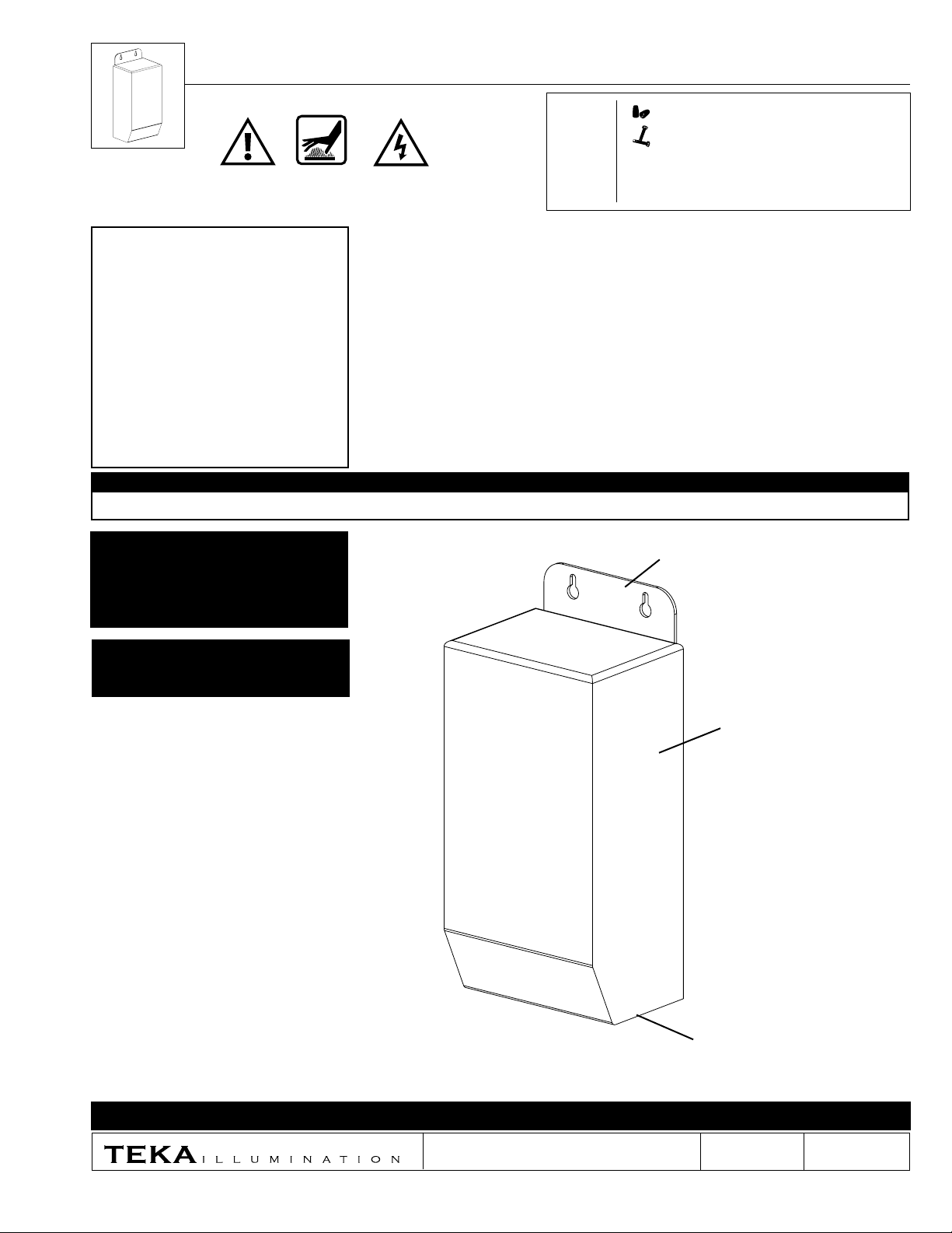
Mounting Bracket
(Mounting Hardware By Others)
For LED sourced products, do
not exceed more than 80% of the
maximum load of the transformer.
NEMA 3R Rated
Stainless Steel Housing
TR300-120
Three (3) 7/8” Dia. Knockouts
(Not Shown)
IMPORTANT SAFETY INFORMATION - READ, FOLLOW, AND SAVE THESE INSTALLATION INSTRUCTIONS
40429 Brickyard Drive • Madera, CA 93636 • USA
THIS DOCUMENT CONTAINS PROPRIETARY INFORMATION OF TEKA ILLUMINATION AND ITS RECEIPT OR POSSESSION DOES NOT CONVEY ANY RIGHTS TO REPRODUCE, DISCLOSE ITS CONTENTS, OR TO MANUFACTURE, USE OR SELL ANYTHING IT MAY
DESCRIBE. REPRODUCTION, DISCLOSURE OR USE WITHOUT SPECIFIC WRITTEN AUTHORIZATION OF TEKA ILLUMINATIONIS STRICTLY FORBIDDEN.
www.tekaillumination.com • info@tekaillumination.com
559.438.5800 • FAX 559.438.5900
RELEASED
02-06-18
REFERENCE NUMBER
INS-2456-00
Installation Instructions
LINE (Black)
COM (White)
GROUND (Green)
60
TRANSFORMER
LINE (Black)
COM (White)
GROUND (Green)
60
LINE (Black)
COM (White)
GROUND (Green)
LINE (Black)
Fixture
COM (White)
GROUND (Green)
12VAC Secondary (White)
COM Secondary (White)
13V BOOST
(Orange - Capped)
TRANSFORMER
(in Housing)
TRANSFORMER
TR300 SERIES™
120V Magnetic Transformer
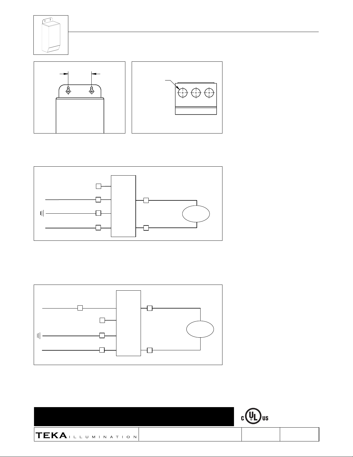
2-7/16”
1. For TR300: Mount transformer stainless steel
housing with proper hardware for surface
(Hardware By Others). Clearance holes are
2-7/16” apart on center.
13V BOOST
(Orange - Capped)
LINE (Black)
GROUND (Green)
COM (White)
(3) 7/8" Dia.
Knockouts
2. Stainless steel housing has three (3) 7/8” diameter
knockouts located on bottom of housing.
12VAC Secondary (White)
(in Housing)
Fixture
COM Secondary (White)
WIRING DIAGRAM - 12V Output
3A. For 12V output wiring: Ground incoming primary ground wire to green wire from TR housing. Make
watertight connections from incoming primary line voltage (black) to black primary side of transformer.
Connect incoming primary common (white) to white primary side of transformer. Orange boost wire from
primary side of transformer must be capped for 12V wiring. Connect secondary side of transformer (white
wires) to fixture leads. See wiring diagram.
LINE (Black)
GROUND (Green)
COM (White)
WIRING DIAGRAM - 13V Output
3B. For 13V output wiring: Ground incoming primary ground wire to green wire from TR housing. Make
watertight connections from incoming primary line voltage (black) to orange boost wire from primary side
of transformer. Connect incoming primary common (white) to white primary side of transformer. Black wire
from transformer primary side must be capped for 13V wiring. Connect secondary side of transformer (white
wires) to fixture leads. See wiring diagram.
READ, FOLLOW, AND SAVE ALL SAFETY AND INSTALLATION INSTRUCTIONS
13V BOOST
(Orange)
(Black - Capped)
(in Housing)
13VAC Secondary (White)
COM Secondary (White)
IMPORTANT SAFETY INFORMATION LISTED ON REVERSE
40429 Brickyard Drive • Madera, CA 93636 • USA
www.tekaillumination.com • info@tekaillumination.com
559.438.5800 • FAX 559.438.5900
Fixture
RELEASED
02-06-18
REFERENCE NUMBER
INS-2456-00
 Loading...