

Page 1

Code Nº: PRM-00-0001
INSTALLER’S MANUAL
Revised / Date: 2006
Page Nº: 26 of 95
3 HOBS
When fitting a hob, installers should bear in mind the following series of important
recommendations in order to ensure the safety and correct working of the appliance:
During fitting, recessed hobs should be handled with care to prevent damage to the edges
or the glass surface of vitroceramic models.
With vitroceramic models, carefully check the glass surface to ensure there are no cracks.
Should there be even the slightest crack, do not
If the hob is to be recessed over an oven, carefully follow all speci fications indicated to
ensure correct ventilation.
Before installing, ensure that the gas supply characteristics are compatible with the
regulations indicated on the specification plate (gas type and pressure).
Installation and maintenance of the hob should be carried out by qualified personnel in
accordance with existing regulations.
proceed with installation.
Cabinet adhesives should be resistant to temperatures of 100ºC (Y type protection against
overheating, in compliance with the EN 60335-2-6 standard).
Minimum distances between the hob and extractor hood should be strictly observed: 65 cm
for electric hobs 70 cm for gas and mixed hobs.
Recess measurements should be similarly observed.
Recessed hobs with reinforced plates should be installed more than 15 cm away from side
walls. All other hobs should be installed at a distance of more than 10 cm.
The hobs referred to in this installation manual are compatible with TEKA ovens. In this
case consult the corresponding manual before installing.
The installation process does not differ much from model to model. Below are installation
instructions for each model in the range with both independent and ME controls and for gas,
electric and mixed models.
26
Page 2
Code Nº: PRM-00-0001
INSTALLER’S MANUAL
Revised / Date: 2006
Page Nº: 27 of 95
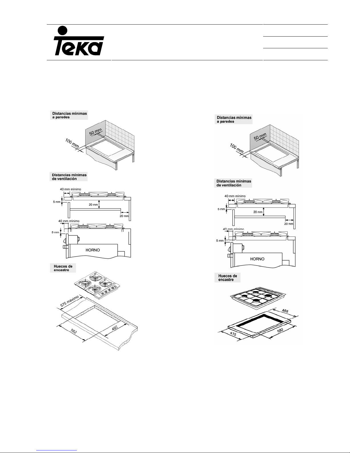
3.1 INSTALLATION OF HOB:
E/60.2 AND ES/60.2 E/50
(1) Minimum distance to wall (1) Minimum distance to wall
(2) Minimum ventilation distance (2)Minimum ventilation distance
(3) Space for recess (3) Space for recess
27
Page 3
Code Nº: PRM-00-0001
INSTALLER’S MANUAL
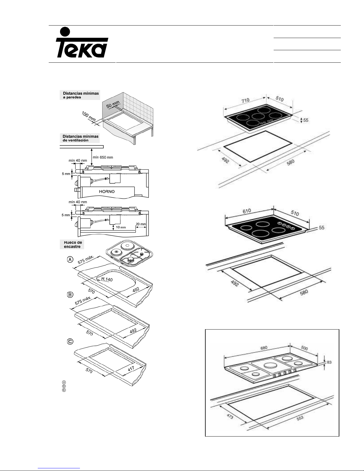
SM AND CG, EC AND CGC, ECC
Minimum distance to wall
(1)
CG LUX 60
CG LUX 70
Revised / Date: 2006
Page Nº: 28 of 95
(2) Minimum ventilation distance
(3) Space for recess
28
Page 4
Code Nº: PRM-00-0001
INSTALLER’S MANUAL
Revised / Date: 2006
Page Nº: 29 of 95
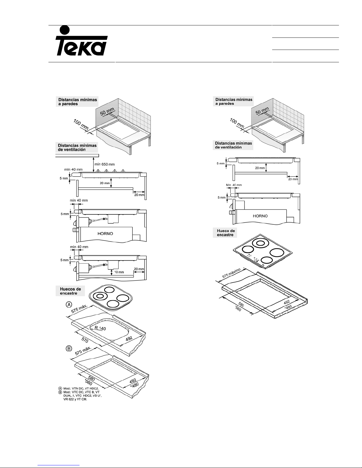
VITROCERAMIC HOBS
(1) Minimum distance to wall (1) Minimum distance to wall
(2) Minimum ventilation distance (2) Minimum ventilation distance
TT 620
TR 620
TR 620, TZ620 AND TR640TR 620, TZ620 AND
TR640
(3) Space for recess (3) Space for recess
Depending on the model in question, the recessing system is designed for cabinets with a work
surface thickness of 20, 30 and 40 mm. In the event that a separation board is not required, the
29
Page 5

Code Nº: PRM-00-0001
INSTALLER’S MANUAL
induction models nºs IR/IT 635, IR/IT 645 and IR 735 include a suplementary casing which shoud
be fitted when installing the appliance under a drawer.
Revised / Date: 2006
Page Nº: 30 of 95
30
Page 6
Code Nº: PRM-00-0001
INSTALLER’S MANUAL
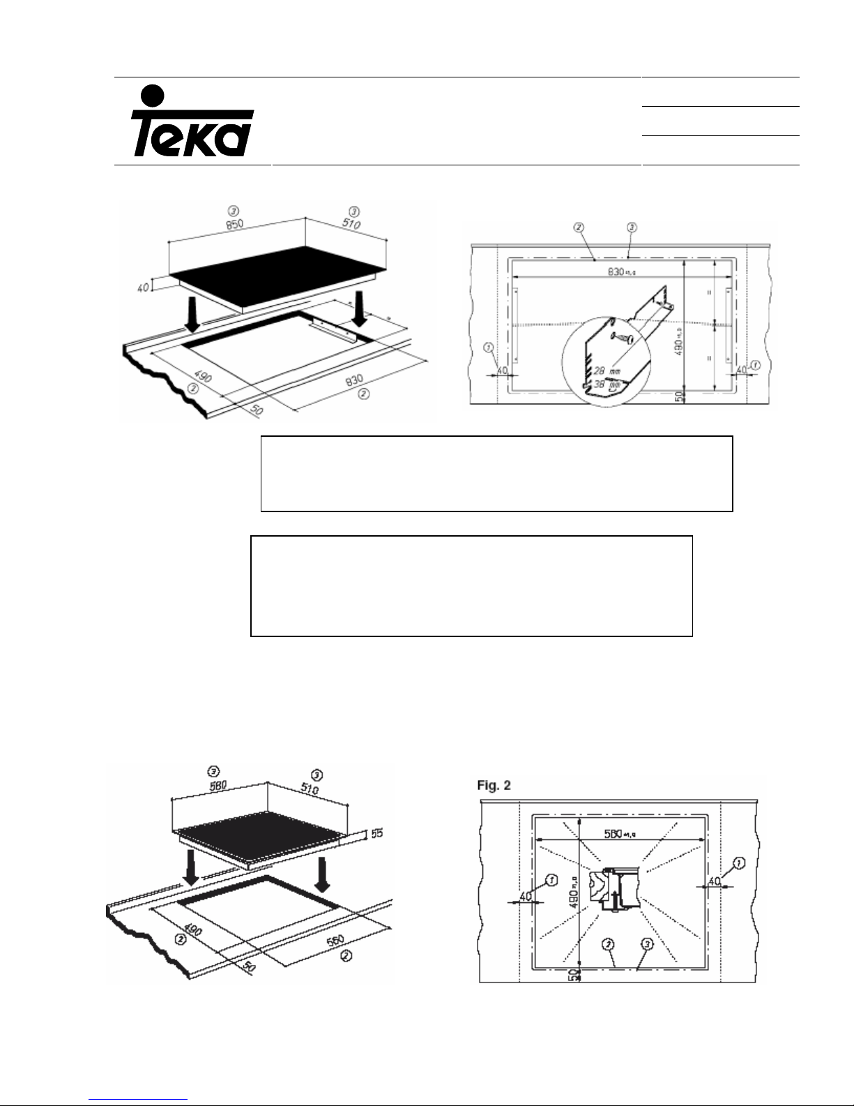
Plate Nº TR 932
1. Minimum distance between ajacent walls
2. Interior cut measurement
3. Exterior work surface measurement
Revised / Date: 2006
Page Nº: 31 of 95
1. Minimum distance between adjacent walls
2. Interior cut measurement
3. Exterior cut measurement
4. External measurement of worksurface
Plates Nºs VI TC 60 2I AND VI TC 60 4I
31
Page 7
Code Nº: PRM-00-0001
INSTALLER’S MANUAL
IR 622, IZ 622, IT622
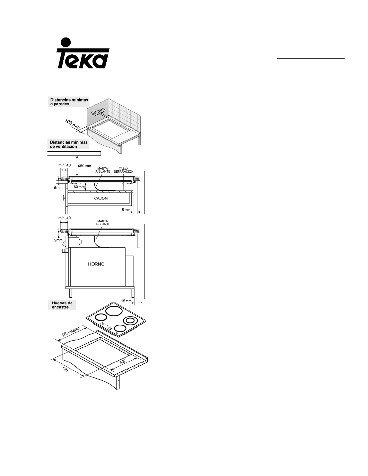
(1) Minimum distance to wall (2) Minimum ventilation distance (3) Space for recess
The installation process is the sa me as for vitroceramic
hobs, bearing in mind it will be necessary to take
greater precautions to ensure improved ventilation for
the recess space.
Ventilation openings will need to be thermally isolated
using the insulating blanket supplied with the hob.
This insulating blanket prevents hot air mixing with the
cold air being sucked in.
Warning! This blanket must not cover ventilation
outlets, preventing the evacuation of air.
Avoid excessive heat build up in the hob.
Revised / Date: 2006
Page Nº: 32 of 95
NOTE: Induction hobs should not be installed above an oven that does not feature forced
ventillation.
32
Page 8
Code Nº: PRM-00-0001
INSTALLER’S MANUAL
3.2 FITTING THE HOB TO ITS RECESS
-{}-
Revised / Date: 2006
Page Nº: 33 of 95
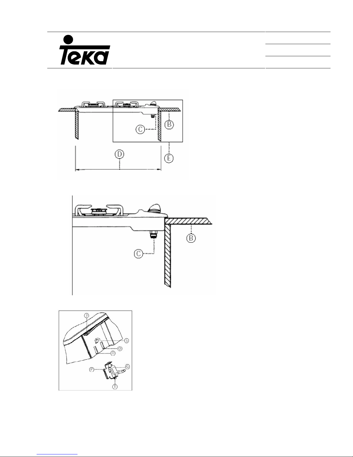
C-SerieSoftplate
B - How to fit this plate in a 60cm
cabinet
D - 60 cm cabinet
E - Detail
The minimum vertical distance from
the hob to the cabinet is 600 mm.
Cristal Gas Series
-{}-
The fitting process is identical to that for other
models.
1) Attach seal “J”.
2) Fix the four clips “G” using the two tabs “P”,
in the spaces “O” in the hob.
3) Tighten the screws “T”.
See illustration.
33
Page 9
Code Nº: PRM-00-0001
INSTALLER’S MANUAL
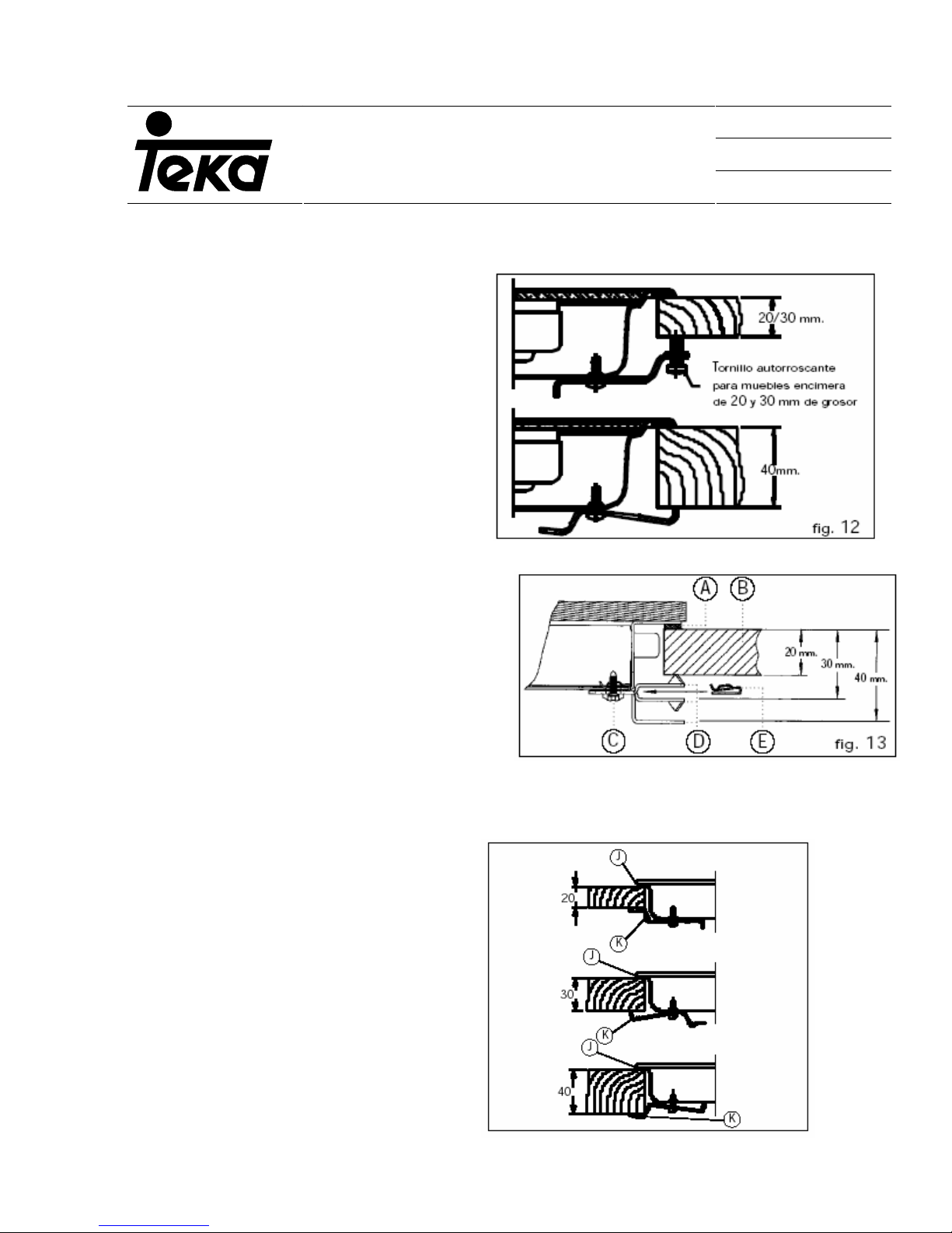
For models Nºs CG.1 4G, CG.1 3G1P and Vitroceramics:
(1)
Place the attachment clips as
shown in the illustration (fig. 12)
If thickness is equal to 30mm,
use self threading screws (M5)
For model Nº CGC AI AL:
Insert the push nuts into the screw
housings (See figure 13).
Self threading screw for kitchen cabinets with a thickness of 20 mm or 30 mm
Revised / Date: 2006
Page Nº: 34 of 95
Having attached the clip which
corresponds to the thickness of the
surface (20, 30 or 40mm), fully tighten all
screws.
Key :
A – Leaktight seal B – Work surface C - Screw
D – Attachment clip E – Push nut
CGC 4G AI AL plate and Soft Series:
Step 2
After checking that the cabinet
measurements are correct, it is
necessart to attach the leaktightness
seale (J) under the hob.
Step 3
Place the clips (K) as shown in the
illustration (fig. 15) attaching them to
the gaps in the lower part of the
housing with the 4.2mm thread screws.
The clips, seal and screws are all
supplied with the appliance.
Fig. 4
34
Page 10
Code Nº: PRM-00-0001
INSTALLER’S MANUAL
In the 600x510 series, the procedure for fitting the plate is identical to other procedures.
Fig. 5
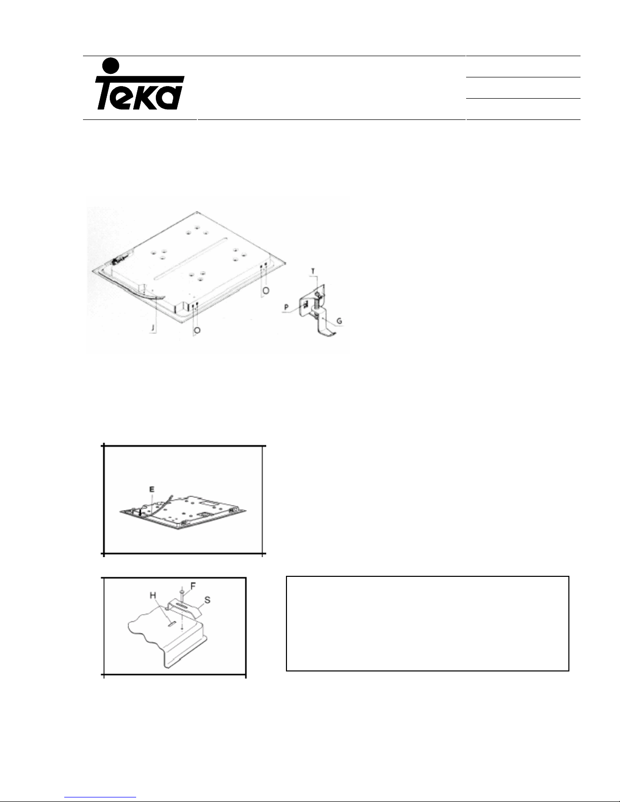
This hob is designed to be recessed into
worktop surfaces with a thickness of 20, 30
or 40 mm.
Attach the leaktight seal “J” underneath the
hob.
Fix the four clips “G” using the two tabs “P”,
in the spaces “O” in the hob.
Next, place the hob in the space and tighten
the screws “T” of the 4 clips with the
corresponding key.
Revised / Date: 2006
Page Nº: 35 of 95
For the EX/70 series, the fitting process is as follows:
1) Turn the hob and correctly position the adhesive
side of the the seal “E” (see fig.) around the edge.
2) The ends of the seal should be joined together
without overlapping.
3) Place the hob in the space.
-{}-
4) Attach with the clips “S”, carefully introducing the
tab into the slot “H” on the bottom of the hob.
5) Tighten screw “F” until it holds clip “S” to the cover
(see illustration).
-{}-
35
Page 11
Code Nº: PRM-00-0001
INSTALLER’S MANUAL
Revised / Date: 2006
Page Nº: 36 of 95
TR 932
For all models with bevelled edges, before
installing the hob it is necessary to remove any
remains of material and check that the seal is
correctly in place. It is also important that silicone
is not used as there is a risk of breakage when
dismantling.
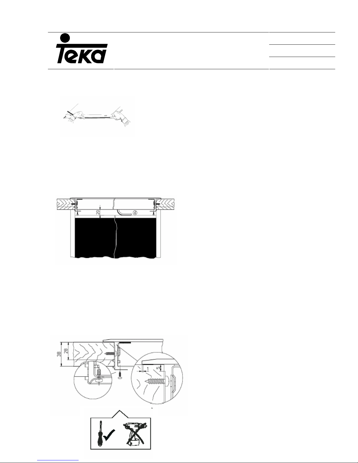
When the hob is fitted into kitchen cabinets, the installer needs to ensure that there is no contact
between the bottom of the hob and the cabinet. In order to guarantee this it is necessary to fit
some protection which may only be removed with tools.
This protection should be placed at least 20 mm
from the bottom of the hob so that the mains
electric supply cable does not come into contact
with the hob.
The back of the lower cabinet needs to feature an opening in order that air may freely circulate.
The wood on the front of the cabinet shoud be removed to ensure an opening that will allow air to
reach the inside of the space where the hob is located.
The distance between the hob and the cabinet should be large enough to ensure sufficient
ventilation.
Carefully position the hob in the recess
space and attach with the respective
clips. Tighten the screws until it is
correctly fixed in place.
36
Page 12
Code Nº: PRM-00-0001
INSTALLER’S MANUAL
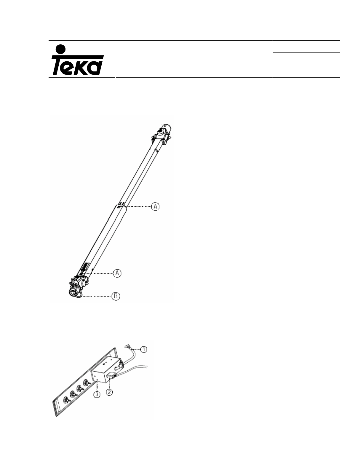
3.3 FIXING CARDANS IN CONTROL - FREE HOBS TO OVEN TEKA
1) Disconnect the electrical supply.
2) Remove the telescopic attachments by pushing
the small button marked PUSH (A) with the point
of a screwdriver until it can be pulled out a few
centimetres.
3) Remove the four fasters from the ends.
4) Partially insert the oven into the space in the
instalation, bearing in mind that the cardan on
the hob should not be moved. A space needs to
be left in order to be able to insert the other end
of the cardan into the back part of the control
panel, and then attaching the fasteners.
5) For electrical connection, connect the hob to the
oven.
6) Place the oven carefully into the recessed
opening and check that the cardans are
correctly connected.
7) Attach the contols to the oven’s control panel.
8) In order for the controls to work correctly, press
in and then turn to free them from the safety
catch.
If the cardans are too short it is possible to attach an
elongation.
Revised / Date: 2006
Page Nº: 37 of 95
Rear view of control panel
37
Page 13

Code Nº: PRM-00-0001
INSTALLER’S MANUAL
Revised / Date: 2006
Page Nº: 38 of 95
With respect to the CGC 4G AI AL hob
Connecting the hob to the oven is carried out in the same way as before, apart from step 7, which
needs to be altered:
7) Fit the oven trim as instructed in the accompanying manual. Take care to fit the trim correctly.
3.4 GAS CONNECTION
We would like to remind you once more that connecting the hob to the gas supply should always
be carried out in strict accordance with current installation regulations.
The appliance should be installed in a kitchen that is adequately ventilated, as stipulated in the
current installation regulations.
The hob should be connected to the gas supply via a me tal tube. This tube should be placed in
order that it does not touch any moving part of the cabinet or other electrical appliances.
It should be situated in a place where it cannot be obstructed and where its entire length, which
should not exceed 2 metres, may be inspected.
The hob is equipped with a ½” diametre connection, in compliance with the ISO 228-1 standard.
10/12mm copper tubing is also supplied, which should be soldered to the gas supply pipe. Each
time the connecting nut is dismantled, the joint should be changed.
In order to prevent damage to the hob, when tightening the nut on the gas supply pipe, use a tool
with a maximum grip of 350Kgf/cm.
Once the appliance has been connected to the gas, check it for leaktightness. If you intend to do
this with compressed air, bear in kind that test pressure should not exceed 200g/cm
2
. In the event
that the test is carried out with gascheck tightness with water and soap. NEVER USE A NAKED
FLAME!
Minimum flame adjustment
Once the hob has been correctly fitted, check that the minimum flame level is well regulated. In
order to do this, light the gas rings and turn the control quickly from maximum to minimum. If the
flame goes out, they will need to be adjusted.
38
Page 14
Code Nº: PRM-00-0001
INSTALLER’S MANUAL
3.5 ELECTRICAL CONNECTION
Before connecting the hob to the mains supply, check that the voltage and frequency correspond
to the characteristics on the specification panel (situated underneath the appliance).
Ensure that the connection to the mains supply is at the correct voltage.
Mains supply should be provided via a suitable omnipolar switch with a 3mm miminum gap
between contacts and which can carry the re quired maximum ampage, ensuring that disconnection
in case of emergency or appliance cleaning is guaranteed.
Take care to ensure that the mains supply cable is not in contact with the hob casing.
For those models which do not include a mains supply cable, in order to connect the appliance,
remove the cover situated underneath the hob in order to gain access to the connection terminal.
Having successfully connected the appliance, replace the cover and secure the mains cable with a
jubilee clip in order to prevent pressure on the cable.
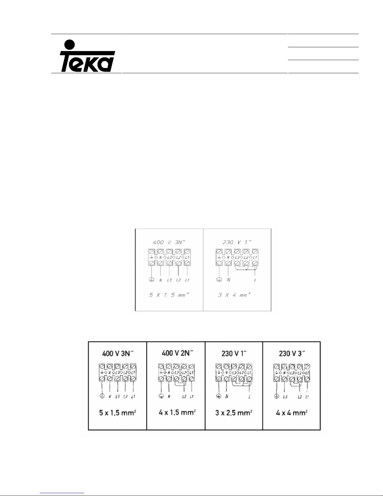
The mains supply cable should be at least the H05 VVF type.
Possible electrical connections
TR 932
Revised / Date: 2006
Page Nº: 39 of 95
Induction
39
Page 15
Code Nº: PRM-00-0001
INSTALLER’S MANUAL
4 CONTROL PANEL
4.1 INSTALLATION
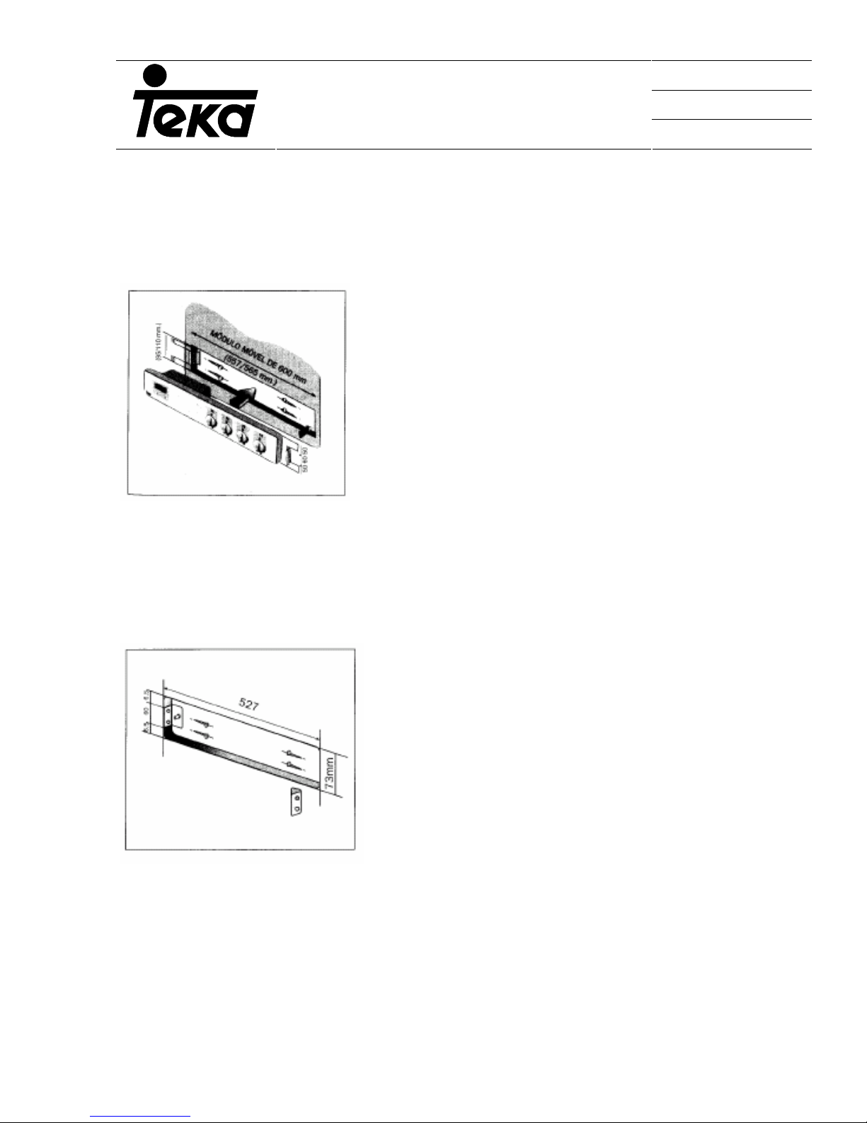
LUX glass control panels
Exterior measurements of the panel:
597x120mm
Revised / Date: 2006
Page Nº: 40 of 95
Make an opening in the kitchen cabinet with the
following measurements: 557 / 565 mm long, 95 /
110mm high.
Screw in the two fixing plates so that the shafts can
be inserted into the control panel. The left hand
plaque should be placed in such a way that the semi
circle appears on the up per side of the plate, whilst
the hand side plaque should appear with the semi
circle on the lower side of the plate.
To connect the hob to the control panel, insert the
hob connector into the back of the panel.
Attach the cardans.
Insert the panel, introducing it from right to left i nto
the shafts of the fixing plate.
Glass control panels
Exterior measurements of the panel:
560x85mm
Make an opening in the kitchen cabinet with the
following measurements: 527x 70 mm.
Screw in the two fixing plates so that the shaft can
be inserted into the control panel.
To connect the hob to the control panel, insert the
hob connector into the back of the panel.
Attach the cardans.
Insert the panel, introducing it from right to left into
the shafts of the fixing plates.
40
Page 16
Code Nº: PRM-00-0001
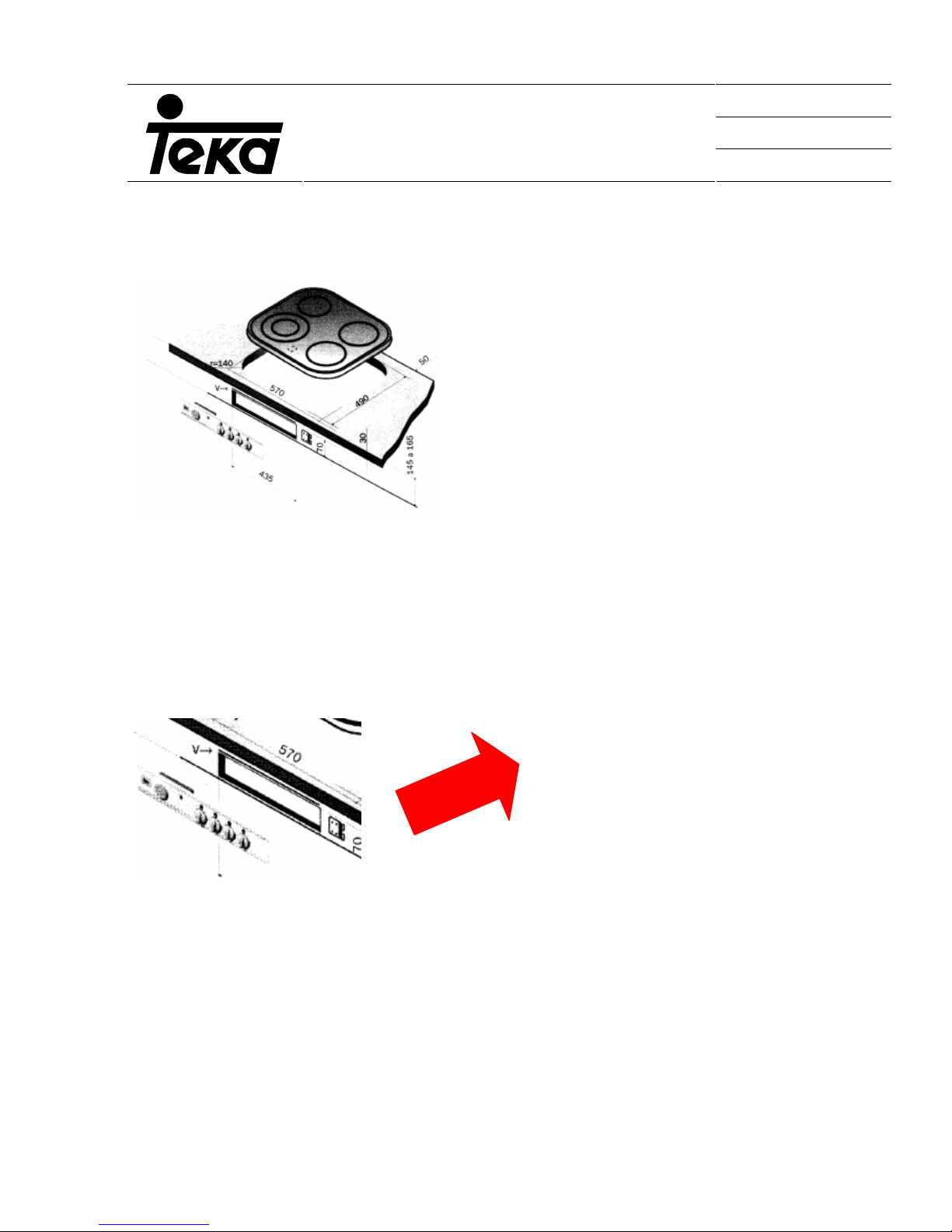
For all models, a minimum opening of
ventilation
Metallic control panels
INSTALLER’S MANUAL
Make an opening in the kitchen cabinet with the following
measurements: 435 x 70 mm.
To make this opening, draw the outline and the
attachment holes with the paper stencil supplied with the
panel.
Attach the plate with 4 screws so that the higher part is to
the right.
Insert the panel from right to left within the the plate that
has just been attached.
Check that the panel is in the correct place and finish
attachment.
To connect the hob to the control panel, insert the hob
connector into the back of the panel.
Attach the cardans.
Revised / Date: 2006
Page Nº: 41 of 95
50 cm² is needed to ensure adequate
41
Page 17
Code Nº: PRM-00-0001
INSTALLER’S MANUAL
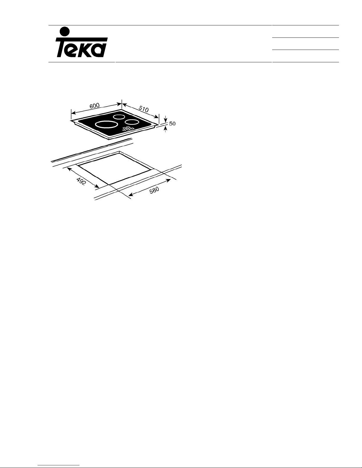
Models IR/IT 635, IR 735 and IR/IT 645 feature new casings manufactured from synthetic glass
fibre which allow for a reduction in the height of the hob, improving their installation above other
electrical appliances such as ovens, dishwashers or even closed drawers.
Revised / Date: 2006
Page Nº: 42 of 95
42
 Loading...