

Instructions for the installation
and advice for the maintenance
EF/60 4G AI - E/70 5G AI TR
Manual of instruct ions
EF/60 4G AI - E/70 5G AI TR
COD. 01001AU – 18.06.2002
2
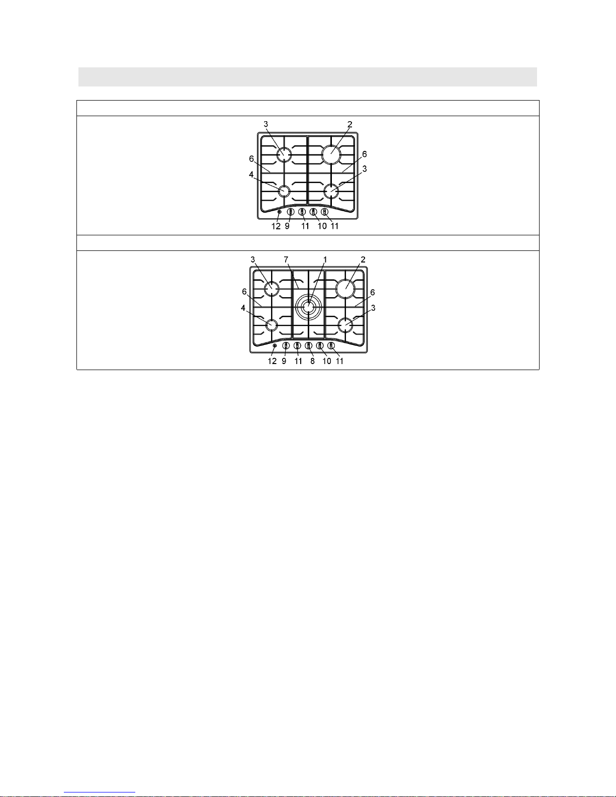
DESCRIPTION OF THE HOT PLATES
MODEL : 40220501
MODEL : 40220050
LPG NG
1 Ultra rapid burner of 11.9 MJ/h 15.0 MJ/h
2 Rapid gas burner of 10.8 MJ/h 12.0 MJ/h
3 Semirapid gas burner of 6.3 MJ/h 7.3 MJ/h
4 Auxiliary gas burner 3.6 MJ/h 4.2 MJ/h
6 Enamelled steel pan support 2F
7 Central enamelled steel pan support
8 Burner n° 1 control knob
9 Burner n° 4 control knob
10 Burner n° 2 control knob
11 Burner n° 3 control knob
12 Electric ignition button
Attention: this appliance has been manufactured for domestic use only and it
employment by private person.
The natural gas regulator to be set at 1kPa with the Wok and Semi-Rapid burner
opera ting a t maximu m.
3
USE
1) BURNERS
A diagram is screen-printed above each knob on the front panel. This diagram indicates to
which burner the knob in question corresponds. After having opened the gas mains or gas
bottle tap, light the burners as described below:
− Manual ignition
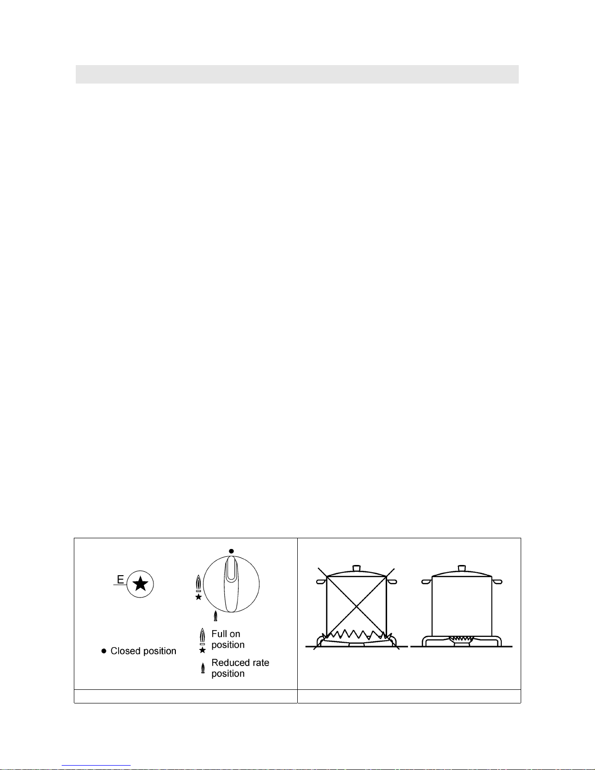
Push and turn the knob corresponding to the required burner in an anticlockwise direction
until it reaches the full on position (large flame fig. 1), then place a lighted match near the
burner.
− Electrical ignition
Push and turn the knob corresponding to the required burner in an anticlockwise direction
until it reaches the full on position (large flame fig. 1), then depress and release the ignition
button.
− Automatic electrical ignition
Push and turn the knob corresponding to the required burner in an anticlockwise direction
until it reaches the full on position (large flame fig. 1), then depress the knob.
− Lighting burners equipped with flame failure device
The knobs of burners equipped with flame failure device must be turned in an
anticlockwise direction until they reach the full on position (large flame fig. 1) and come to
a stop. Now depress the knob in question and repeat the previously indicated operations.
Keep the knob depressed for about 10 seconds once the burner has ignited.
Note: You are advise not to try and light a burner if the flame divider (Burner Cap) is
not correctly place.
In the event of the Burner flames being accidentally extinguished, turn off the
burner control and do not attempt to re-ignite the burner for a least 1 minute.
HOW TO USE THE BURNERS
Bear in mind the following indications in order to achieve maximum efficiency with the least
possible gas consumption:
− Use adequate pans for each burner (consult the following table and fig. 2).
− When the pan comes to the boil, set the knob to the reduced rate position (small
flame fig. 1).
− Always place a lid on the pans.
− Use only pan with a flat bottom and in thick metal.
Burners Power ratings Pan Ø in (cm)
LPG NG
Ultra rapid 11.9 MJ/h 15.0 MJ/h 22 ÷ 24
Rapid 10.8 MJ/h 12.0 MJ/h 20 ÷ 22
Semirapid
6.3 MJ/h 7.3 MJ/h 16 ÷ 18
Auxiliary 3.6 MJ/h 4.2 MJ/h 10 ÷ 14
WARNINGS:
- Burners with flame failure device may only beignited when the relative knob
has been set to the Full on position (large flame fig. 1).
- Matches can be used to ignite the burners in a blackout.
- Never leave the appliance unattended when the burners are being used. Make
sure there are no children in the near vicinity. Particularly make sure that the
pan handles are correctly positioned and keep a chek on foods requiring oil
and grease to cook since these products can easily catch fire.
4
USE
- Never use aerosols near the appliance when it is operating.
- If the built-in hot plate has a lid, any spilt food should be immediately
removed from this before it is opened. If the appliance has a glass lid, this
could shatter when the hot plate becomes hot. Always switch off all the
burners before closing the lid.
- Do not store or use flammable liquids or items in the vicinity of the hotplate.
FIG. 1 FIG. 2
5
USE
Notes:
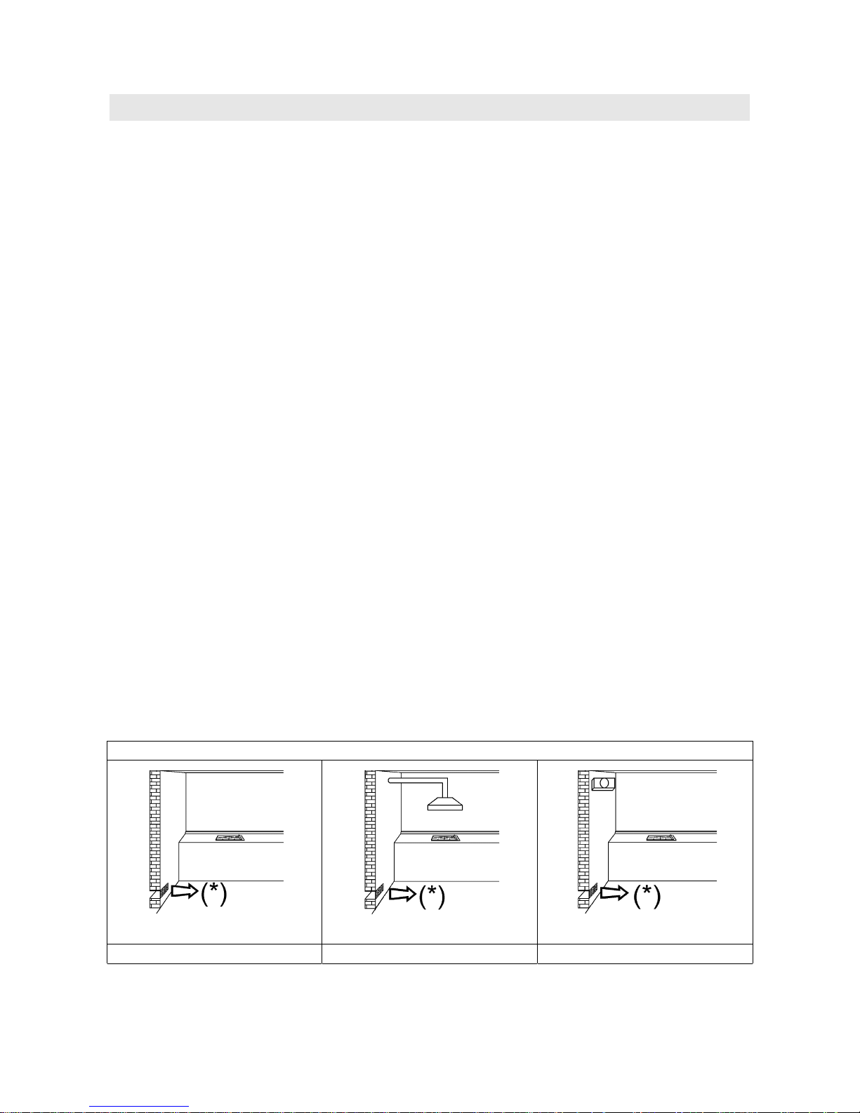
Use of a gas cooking appliance produces heat and moisture in the room in which it
is installed. The room must therefore be well ventilated by keeping the natural air
vents clear (fig. 3) and by activating the mechanical aeration device (suction hood
or electric fan fig. 4 and fig. 5).
Intensive and lengthy use of the appliance may require additional ventilation. This
can be achieved by opening a window or by increasing the power of the mechanical
exhausting system if installed.
Abnormal Operation:
Any of the following are considered to be abnormal operation and may require
servicing:
- Yellow tipping of the hob burner flame.
- Sooting up of cooking utensils.
- Burners not igniting properly.
- Burners failing to remain alight.
- Burners extinguished by cupboard doors.
- Gas valves which are difficult to turn.
(*) Air inlet – minimum section 100 cm2
FIG. 3 FIG. 4 FIG. 5
 Loading...