

Teka E/60.2, ES/60.2, E/50, SM, CG Installer Manual
...
Code Nº: PRM-00-0001
INSTALLER’S MANUAL
Revised / Date: 2006
Page Nº: 26 of 95
3 HOBS
When fitting a hob, installers should bear in mind the following series of important
recommendations in order to ensure the safety and correct working of the appliance:
During fitting, recessed hobs should be handled with care to prevent damage to the edges
or the glass surface of vitroceramic models.
With vitroceramic models, carefully check the glass surface to ensure there are no cracks.
Should there be even the slightest crack, do not
If the hob is to be recessed over an oven, carefully follow all speci fications indicated to
ensure correct ventilation.
Before installing, ensure that the gas supply characteristics are compatible with the
regulations indicated on the specification plate (gas type and pressure).
Installation and maintenance of the hob should be carried out by qualified personnel in
accordance with existing regulations.
proceed with installation.
Cabinet adhesives should be resistant to temperatures of 100ºC (Y type protection against
overheating, in compliance with the EN 60335-2-6 standard).
Minimum distances between the hob and extractor hood should be strictly observed: 65 cm
for electric hobs 70 cm for gas and mixed hobs.
Recess measurements should be similarly observed.
Recessed hobs with reinforced plates should be installed more than 15 cm away from side
walls. All other hobs should be installed at a distance of more than 10 cm.
The hobs referred to in this installation manual are compatible with TEKA ovens. In this
case consult the corresponding manual before installing.
The installation process does not differ much from model to model. Below are installation
instructions for each model in the range with both independent and ME controls and for gas,
electric and mixed models.
26
Code Nº: PRM-00-0001
INSTALLER’S MANUAL
Revised / Date: 2006
Page Nº: 27 of 95
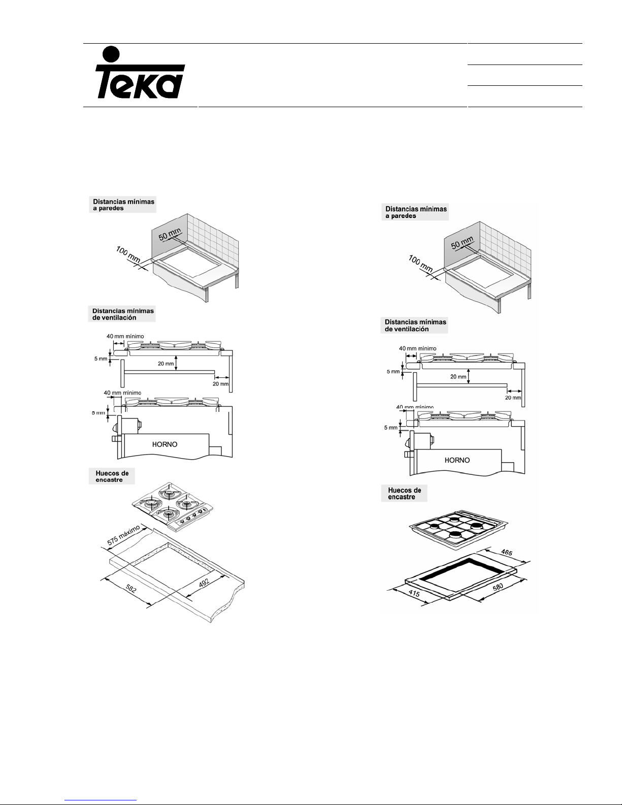
3.1 INSTALLATION OF HOB:
E/60.2 AND ES/60.2 E/50
(1) Minimum distance to wall (1) Minimum distance to wall
(2) Minimum ventilation distance (2)Minimum ventilation distance
(3) Space for recess (3) Space for recess
27
Code Nº: PRM-00-0001
INSTALLER’S MANUAL
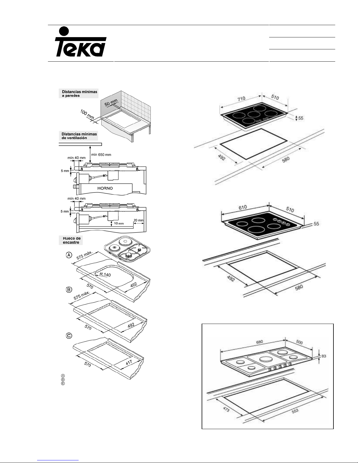
SM AND CG, EC AND CGC, ECC
Minimum distance to wall
(1)
CG LUX 60
CG LUX 70
Revised / Date: 2006
Page Nº: 28 of 95
(2) Minimum ventilation distance
(3) Space for recess
28
Code Nº: PRM-00-0001
INSTALLER’S MANUAL
Revised / Date: 2006
Page Nº: 29 of 95
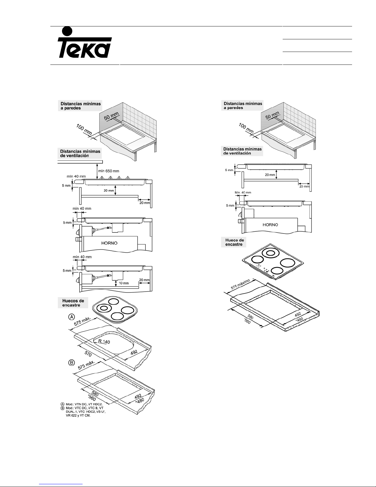
VITROCERAMIC HOBS
(1) Minimum distance to wall (1) Minimum distance to wall
(2) Minimum ventilation distance (2) Minimum ventilation distance
TT 620
TR 620
TR 620, TZ620 AND TR640TR 620, TZ620 AND
TR640
(3) Space for recess (3) Space for recess
Depending on the model in question, the recessing system is designed for cabinets with a work
surface thickness of 20, 30 and 40 mm. In the event that a separation board is not required, the
29

Code Nº: PRM-00-0001
INSTALLER’S MANUAL
induction models nºs IR/IT 635, IR/IT 645 and IR 735 include a suplementary casing which shoud
be fitted when installing the appliance under a drawer.
Revised / Date: 2006
Page Nº: 30 of 95
30
Code Nº: PRM-00-0001
INSTALLER’S MANUAL
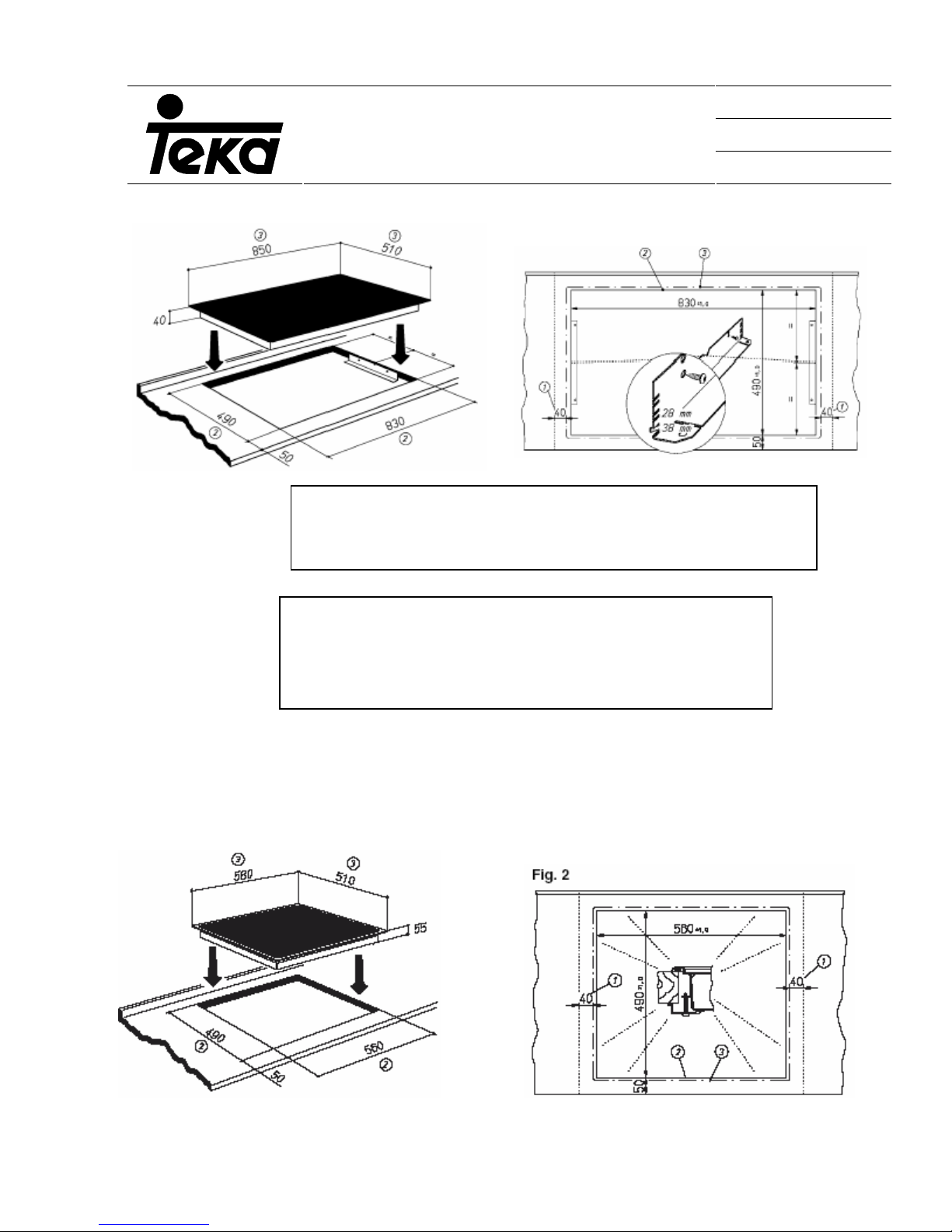
Plate Nº TR 932
1. Minimum distance between ajacent walls
2. Interior cut measurement
3. Exterior work surface measurement
Revised / Date: 2006
Page Nº: 31 of 95
1. Minimum distance between adjacent walls
2. Interior cut measurement
3. Exterior cut measurement
4. External measurement of worksurface
Plates Nºs VI TC 60 2I AND VI TC 60 4I
31
 Loading...