

Page 1

Operating instructions
(Translation of the original operating instructions)
Caremaster 1 - IFA
Caremaster 2 - IFA
TEKA Absaug- und Entsorgungstechnologie GmbH, Industriestraße 13, D-46342 Velen,
Tel.: +49 2863-9282-0, E-Mail: info@teka.eu, www.teka.eu
1
Page 2

Table of contents
1 General 4
2 Description of the system elements 5
2.1 Illustration of the system elements 5
2.2 Functionality of the system 6
2.3 Intended use 6
3 Safety instructions 7
3.1 Definition of the hazard symbols 7
3.2 General safety instructions 7
4 Storage, transport and installation of the device 8
5 Commissioning 8
5.1 Connecting an extraction element 9
5.2 Electrical connection 9
6 Operating the system 10
6.1 Explanation of the operating elements 10
7 Maintenance 11
7.1 Reset to maintenance state 12
7.2 Replacing the prefilter mat 12
7.3 Replacing the particle filter 13
8 Dismantling / Disposal 14
9 Diagnostics and troubleshooting 15
10 List of spare parts 16
11 Technical data 17
12 EC declaration of conformity 18
13 Training protocol 19
14 Maintenance intervals 20
14.1 Usage-related maintenance 20
14.2 General maintenance 20
14.2.1 Visual inspection of the device 21
BA_Caremaster-1-und-2_IFA_170831 _EN
2
31.08.2017
Page 3

14.2.2 Functional test of the device 21
14.2.3 Electrical test of the electrical lines and earthing connections 22
BA_Caremaster-1-und-2_IFA_170831 _EN
3
31.08.2017
Page 4

1 General
Congratulations on purchasing the product from TEKA.
Our engineers ensure that our devices reflect the state of the art through continuous development.
Nevertheless, misuse or misconduct can endanger your safety. Please observe the following for a
successful use of the device:
Only authorised and instructed personnel can carry out transport, operation,
maintenance and repair of the device. The operator must ensure that the operating
personnel take note of these instructions.
Please read these instructions before operating the device, and observe the safety
precautions to avoid injury!
Store this manual in a safe place! These instructions are to be regarded as a component
of the product!
Adhere to all product notes!
Modifications or conversions that the operator carries out at the device without the
consent of the manufacturer, can lead to new safety hazards or to the loss of warranty
claims.
Observe the manufacturer’s instructions. Contact the manufacturer in case of any
uncertainty:
Tel: +49 2863-9282-0
E-mail: info@teka.eu
BA_Caremaster-1-und-2_IFA_170831 _EN
4
31.08.2017
Page 5
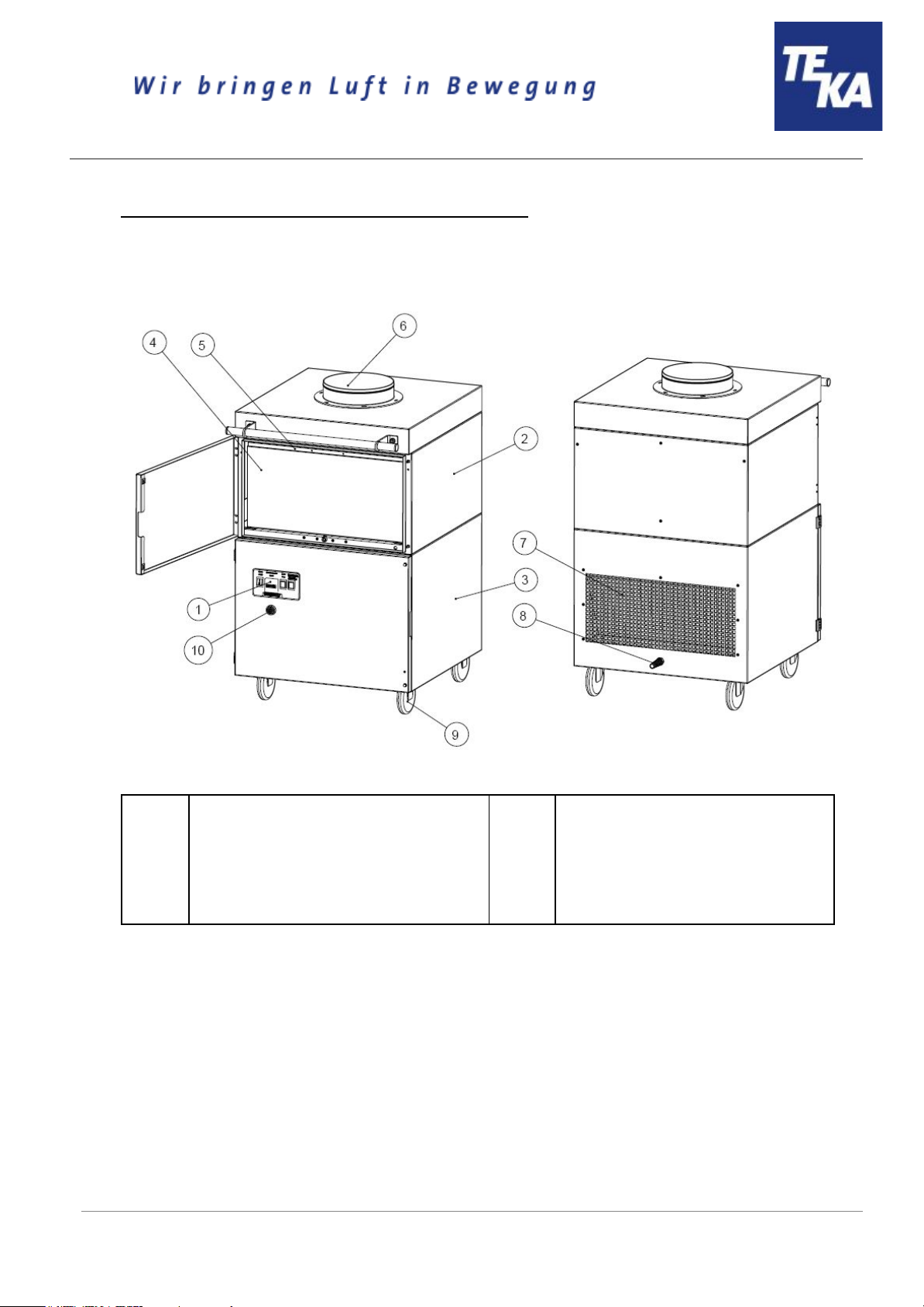
2 Description of the system elements
2.1 Illustration of the system elements
Z.Nr. 17012702
Pos.1
Pos.2
Pos.3
Pos.4
Pos.5
Operating panel of the control
Particle filter housing
Fan housing
Particle filter
Prefilter mat (into guide frame)
Pos.6
Pos.7
Pos.8
Pos.9
Pos.10
Suction nozzle (Caremaster 1: 1x,
Caremaster 2: 2x)
Exhaust grille
Mains cable with plug
Swivel castor
Signal horn
BA_Caremaster-1-und-2_IFA_170831 _EN
5
31.08.2017
Page 6
2.2 Functionality of the system
The filter unit serves to suck off and filter polluted air (according to the intended use). First of all, the
coarse particles are separated at the prefilter mat in the filter section of the unit. The subsequent particle
filter cleans even fine smokes and dusts. An automatic filter monitoring indicates when a cleaning or a
replacement of the filters is necessary. The purified air is led back into the working room.
2.3 Intended use
The filter unit is intended for extraction and filtration of dusts and fumes that result from thermal joining
and cutting of metals. The filter unit is amongst others suitable for separating welding smokes of
unalloyed and alloyed steels as well as of high-alloy chromium-nickel steels and therefore meets the
highest welding fume separation category “W3” according to DIN EN ISO 15012-1.
WARNING
Improper use can damage parts and be a danger to life and limb!
The device must not be used for the extraction of oil-laden welding fume, explosive dust and
gases, hybrid mixtures, glowing or burning substances, gases, water, etc. The device must
not be operated in explosive zones.
BA_Caremaster-1-und-2_IFA_170831 _EN
6
31.08.2017
Page 7
3 Safety instructions
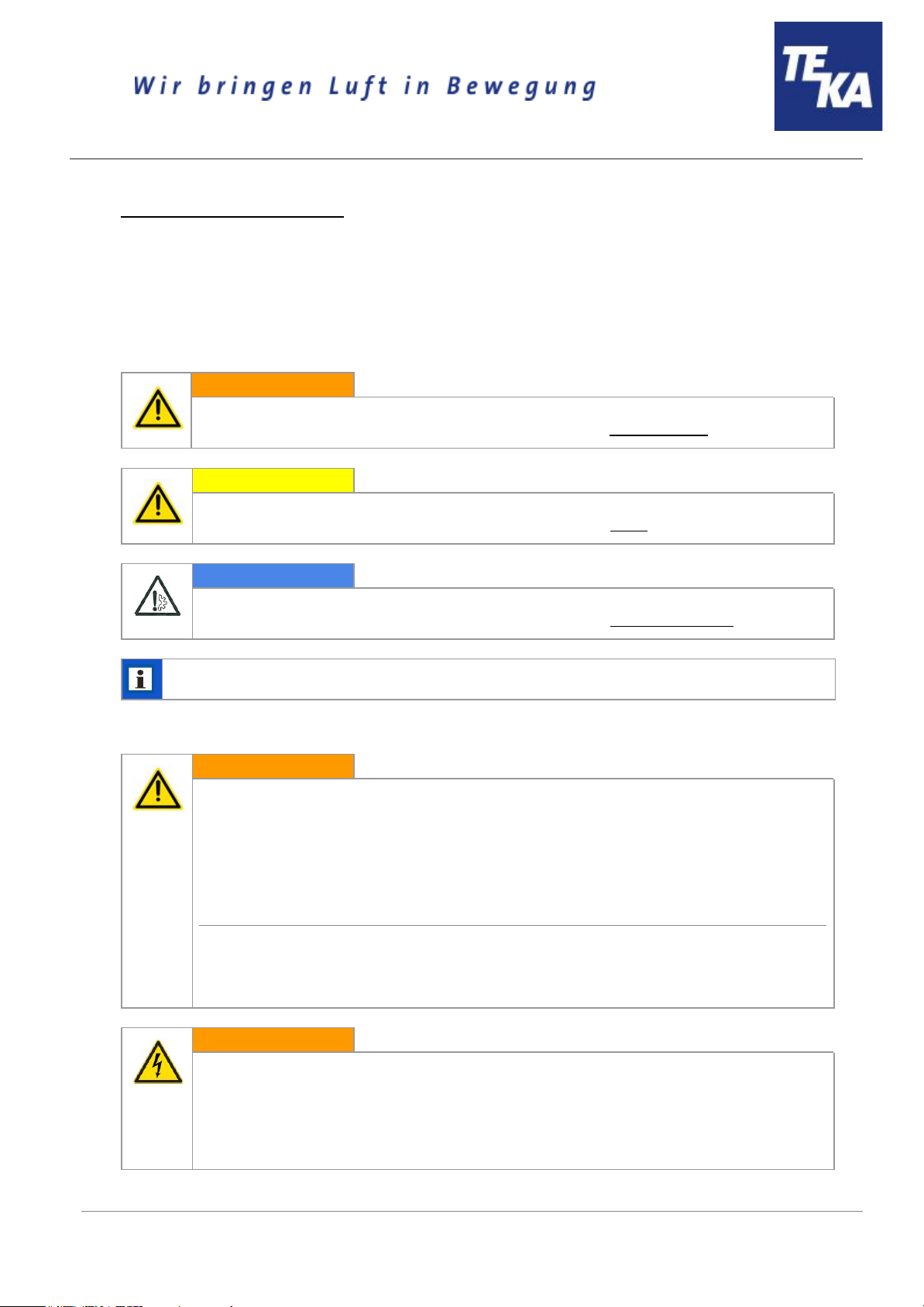
3.1 Definition of the hazard symbols
The device is constructed according to the state of the art and the recognised safety regulations.
Nevertheless, during use threats to life and limb of the user or other persons may arise. The impairment
of the machine or other property are also possible. In these instructions we warn by using corresponding
indications.
WARNING
WARNING
These instructions are made in case of risks that can lead to injury or death.
CAUTION
CAUTION
These instructions are made in case of risks that can lead to injury.
NOTICE
NOTICE
These instructions are made in case of risks that can lead to material damages.
Information notes are no hazard warnings; they call attention to useful information.
3.2 General safety instructions
WARNING
Dangers arising from improper use / unauthorised operations.
The operator must ensure that their authorised personnel are familiar with all the safety
indications in this manual in advance. The operator is responsible for ensuring that all work
is carried out by authorised and qualified personnel. We therefore recommend using the
training protocol on the last page for that purpose (see chapter “Training protocol”).
Laymen are allowed to operate the device after having received the necessary instructions.
But they are not allowed to carry out any installation, repair or maintenance work.
Dangers arising from fire.
In case of fire, if possible, switch the unit immediately off or disconnect it from the power
supply. Fire extinguishing measures which the operator is obliged to determine beforehand
must be initiated immediately.
WARNING
Dangers arising from electricity.
The operator must ensure that electrical plants and equipment are only built, modified and
maintained by a qualified electrician or under the direction and supervision of a qualified
electrician. Do not work on components if you are not sure that these are disconnected. If
necessary, disconnect the device from the electric power supply and secure it against
unauthorized restarting.
BA_Caremaster-1-und-2_IFA_170831 _EN
7
31.08.2017
Page 8

4 Storage, transport and installation of the device
WARNING
Risk of injury from tilting or unmounted components when stored or transported.
The device must be secured against tilting and slipping when it is stored or transported. Do
not stand under or next to the floating load. Lift trucks, forklift trucks and transport cranes
must have a sufficient minimum load bearing capacity. Pay attention to uneven grounds
during the transport. Avoid jerky pushing.
Dangers arising from titling or functional impairments at its destination.
The unit may only be set up on a suitable surface. The surface must be vibration-free and
horizontal. The operator must check the bearing capacity of the surface. As soon as the unit
has reached its intended destination, the brakes of the castors must be activated.
NOTICE
Damage or functional impairment of the unit due to climatic influences.
The unit must be stored in a dry place and protected against moisture during transport. As a
matter of principle, the filter unit is not designed to be installed outside.
5 Commissioning
WARNING
Dangers arising from a defective condition of the unit.
Make sure that the measures described in this chapter are completed before the
commissioning of the unit. All doors of the unit must be closed and all necessary connections
must be attached before turning the unit on. Do not operate the unit if any components are
defective, missing or damaged. Check the orderly condition of the unit before switching it on.
The unit must not be operated without a filter element.
NOTICE
Damaged supply lines.
Make sure that the supply lines are protected against damage by forklift trucks and similar
events. Protect all supply lines from heat, moisture, oil and sharp edges.
BA_Caremaster-1-und-2_IFA_170831 _EN
8
31.08.2017
Page 9

5.1 Connecting an extraction element
For extracting the contaminated air - according to the intended use - the provided extraction element
(e.g. suction arm, suction hose, ...) must be connected at the suction nozzle (see chapter 2.1).
The assembly of a suction arm is described in the separate operating manual.
When using a detection element with extraction hood, the extraction hood must track the welding seam,
possibly taking advantage of the thermally induced welding fume movements.
However, it is important to ensure that connections between the workpiece and the
extractor hood (and generally between the workpiece and filter device) are avoided, so that, if
necessary, the welding current cannot flow back through the protective conductor of the filter
device to the welding machine.
5.2 Electrical connection
NOTICE
Electric malfunction possible in cause of an incorrect power supply.
Pay attention to the admissible supply voltage. Please observe the specifications on the type
plate.
● Reconnect the mains cable (see chapter 2.1) to the power supply.
● Make sure that the fan impeller rotates in the required direction when switching it on for the first
time. If not, it results in a low extraction capacity. For visual inspection, there is a sticker
attached to the bottom of the dust collecting housing (see chapter 2.1). For the connection
points of 400V and 500V the rotating field might be incorrectly set and must be changed, if
necessary. Briefly switch the device on and off. The fan slowly starts running and the rotation
direction can be compared to the sticker.
When the fan rotates in the wrong direction, the extraction capacity is
reduced.
BA_Caremaster-1-und-2_IFA_170831 _EN
9
31.08.2017
Page 10

6 Operating the system
6.1 Explanation of the operating elements
Operating elements for the device control
Representa
tion
Designation
Description / function
ON-OFF-switch
By means of this switch, the device is switched on and off.
When the device is switched off, it is not
disconnected from the power supply.
Operating elements for status and error messages
Representa
tion
Designation
Description / function
Signal lamp “red”
Flashing up means that the air-flow rate of the device is not
sufficient anymore. Filter elements must be cleaned or
replaced.
When using extraction elements with a suction hood, it is
possible that the throttle valve(s) in the suction hood are
closed. In this case open the throttle valves.
Signal horn
Honking signals that the air-flow rate of the device is not
sufficient anymore. Filter elements must be cleaned or
replaced.
When using extraction elements with a suction hood, it is
possible that the throttle valve(s) in the suction hood are
closed. In this case open the throttle valves.
Indicator lamp “green”
Flashing up means that the device is in operation.
Operating hour counter
The number of operation hours during which the device was in
operation is shown.
BA_Caremaster-1-und-2_IFA_170831 _EN
10
31.08.2017
Page 11

7 Maintenance
In accordance with national regulations, the operator is obliged to carry out repeat and functional tests.
Unless otherwise specified by national regulations, we recommend regular visual inspections and
functional tests of the device as described in the chapter “Maintenance intervals”.
You find the chapter “Maintenance intervals” at the end of the document. The general
maintenance (visual inspection, etc.) is also explained there.
In the chapter “Maintenance intervals” there is information on the maintenance intervals of the filter
elements. But these are only recommendations. Depending on the application (multi-shift operation,
dust generation, ...) it may be necessary for the operator to change the maintenance intervals.
In this chapter the maintenance work which is caused by wear caused during operation is described.
WARNING
Work on the open system entails the risk of electrical shock or accidental restart the
system. Both pose a danger to life and limb.
When cleaning and servicing equipment during the replacement of parts or when changing
to another function, set the device to maintenance condition first (see chapter “Reset to
maintenance state”).
A recommissioning of the device must only occur if it is ensured that the device is
functionally equivalent to the original state.
CAUTION
Hazards to the respiratory tracts are possible due to contact with
contaminated filter elements.
All maintenance work must only be carried out in well-ventilated rooms and
while wearing an appropriate respiratory mask! We recommend: respiratory
protection half mask DIN EN 141/143 protection level P3. For all maintenance
work ensure a cautious handling of filter elements and components in order to
avoid whirling up dust.
The operator is obliged to store and dispose of the collected dust in accordance with national or
regional regulations. For all maintenance or cleaning work please refer to the applying
environmental regulations. Pollutants and filter elements must be disposed of or stored according
to the regulations as well. If you have any doubts, we recommend contacting a disposal
contractor in your area.
BA_Caremaster-1-und-2_IFA_170831 _EN
11
31.08.2017
Page 12

7.1 Reset to maintenance state
● Switch off the unit. Unplug the mains plug. Secure the unit against unauthorized restarting
during maintenance.
● After completion of all maintenance work the unit can be reconnected to the power supply.
7.2 Replacing the prefilter mat
The prefilter mat is installed upstream to the particle filter and separates the coarse particles. This
extends the service life of the particle filter.
The prefilter mat must be changed after a certain number of operating hours. The time depends on the
amount of accumulated dust, and therefore cannot be determined beforehand. At the latest, the prefilter
mat must be changed when changing the particle filter.
CAUTION
Whirling up dust is possible.
The prefilter mat is a disposable filter element. Do not try to clean the filter element.
● Open the service door of the particle filter housing (see chapter 2.1).
● Lower the lifting device (A) by turning the clamping screw (B). Therefore, use the hexagon key
that is located on the right of the clamping screw.
● Carefully pull the insert frame (see chapter 2.1) out of the housing.
● Remove the prefilter mat from the insert frame and dispose of or store it according to the
regulations.
● Put a new prefilter mat into the insert frame.
Only use TEKA spare filters. Otherwise the proper functioning of the unit is
not guaranteed.
● Push the insert frame back into the particle filter housing.
● Elevate the lifting device by turning the clamping screw so that the insert frame is pressed
tightly against the above housing.
● Close the service door.
BA_Caremaster-1-und-2_IFA_170831 _EN
12
31.08.2017
Page 13

7.3 Replacing the particle filter
Replacing the particle filter is necessary when the device control signals the corresponding error. (see
chapter "Description of the control elements")
CAUTION
Whirling up dust is possible.
The particle filter is a disposable filter element. Do not try to clean the filter element.
When replacing the particle filter, the prefilter mat must be replaced as well.
● Open the service door of the particle filter housing (see chapter 2.1).
● Lower the lifting device (A) by turning the clamping screw (B). Therefore, use the hexagon key
that is located on the right of the clamping screw.
● Carefully pull the entire filter pack, incl. the particle filter (see chapter 2.1) out of the housing.
● Replace the particle filter.
Only use TEKA spare filters. Otherwise the proper functioning of the unit is
not guaranteed.
● Push the filter pack back into the filter housing. Make sure that the filter elements are inserted in
the correct order.
● Elevate the lifting device by turning the clamping screw so that the upper filter element is
pressed tightly against the above housing.
● Close the service door.
BA_Caremaster-1-und-2_IFA_170831 _EN
13
31.08.2017
Page 14

8 Dismantling / Disposal
Only authorised personnel may disassemble the machine.
WARNING
Dangers arising from electricity.
Before the dismantling of the machine it has to be disconnected from the power supply and
all supply lines.
CAUTION
Whirling up dust is possible due to the deposited dust.
During all work a suitable respiratory protection and protective clothing have to
be worn.
The operator is obliged to store and dispose of the collected dust in accordance with national or
regional regulations.
BA_Caremaster-1-und-2_IFA_170831 _EN
14
31.08.2017
Page 15

9 Diagnostics and troubleshooting
A list of possible system errors is provided in the table.
Faults indicated by control elements are explained in the chapter “Description of the control
elements”.
A recommissioning of the device must only occur if it is ensured that the system is functionally
equivalent to the original state. Repairs may only be carried out by TEKA personnel or, after
consultation with TEKA GmbH, by the personnel authorised by the operator.
Adhere to the instructions in the chapter "Safety instructions" and " Maintenance" when carrying out any
repairs. If in doubt, contact our TEKA service department:
Tel: +49 2863-9282-0
E-mail: info@teka.eu
Fault
Cause
Removal
System does not start.
Plug power supply is missing or
incorrectly inserted.
Plug connector check power
supply / plug in correctly.
No power at outlet.
Check the mains, remove error if
possible.
Dust at the service door
of the filter housing.
The door is not correctly closed.
Close the door.
The seal between the service door and
filter housing is damaged.
The seal must be replaced.
Escape of dust at the hinge.
The hinge must be reoriented or
replaced.
Suction power too low
(smoke hardly
extracted).
Filter element is saturated.
Replace the filter package,
dispose of old filter properly!
Damage at the extraction elements.
Replace the extraction elements.
The motor rotates in the wrong
direction.
The rotating field of mains
connection point must be
changed.
Suction line contracted.
Check and fix.
Exhaust line contracted.
Check and fix.
The system is very noisy.
The motor rotates in the wrong
direction.
The rotating field of mains
connection point must be
changed.
The unit is untight.
Check and fix.
BA_Caremaster-1-und-2_IFA_170831 _EN
15
31.08.2017
Page 16

10 List of spare parts
Filter element
Article no.
Prefilter mat “M5” (10 pieces / 610 x 610 x 20 mm)
10032
Particle filter “H13” (610 x 610 x 292+6)
10030
Particle filter “F9” (610 x 610 x 292+6)
10029
Disposal elements
Article no.
PE-bag for the disposal of filter elements (4 pieces)
10030258
BA_Caremaster-1-und-2_IFA_170831 _EN
16
31.08.2017
Page 17

11 Technical data
Version
Caremaster 1 IFA
Caremaster 2 IFA
Supply voltage
V
230 / 400 / 500
230 / 400 / 500
Frequency
Hz
50
50
Type of current
Ph
1 / 3 / 3
1 / 3 / 3
engine power
kW
1,1
2,2
Air flow volume max.
m³/h
1270
2150
Air flow volume min.
m³/h
780
1600
Negative pressure max.
Pa
1800
2100
Protection class
IP54
IP54
ISO class F
F
Extraction performance
%
> 99
> 99
Welding fume extraction class
(according to EN ISO 15012-1)
W3
W3
Width
Depth
Height
mm
mm
mm
665
681
1050
665
681
1125
Weight
kg
115
120
Sound pressure level
dB(A)
72
74
Allowed ambient temperature
°C
+5 to +35
+5 to +35
Allowed max. humidity
%
70
70
BA_Caremaster-1-und-2_IFA_170831 _EN
17
31.08.2017
Page 18

12 EC declaration of conformity
according to the Machinery Directive 2006/42/EG, Annex II, 1 A
TEKA Absaug- und Entsorgungstechnologie GmbH
Industriestraße 13, D-46342 Velen
Tel.:+49 2863-9282-0 E-Mail: info@teka.eu Internet: www.teka.eu
Designation of the device: Caremaster 1 - IFA / Caremaster 2 - IFA
We hereby declare under our sole responsibility that the product mentioned above, from the serial
number A14500010011001 resp. the production number P28000010011001 on, conforms to the
following directives:
Machinery Directive: 2006/42/EG
Electromagnetic Compatibility: 2014/30/EC
This declaration will become void if the device is exposed to modifications that are not approved by the
manufacturer in written form.
Authorized representative for the technical documentation: Technical department, TEKA GmbH,
D-46342 Velen
(Jürgen Kemper, managing director)
Velen, 3rd january 2017
BA_Caremaster-1-und-2_IFA_170831 _EN
18
31.08.2017
Page 19

13 Training protocol
Designation of the device: Caremaster 1 - IFA / Caremaster 2 - IFA
(This form can be used by the operator to document the training of the employees. Training should be performed by
authorized personnel only. Refer to the instructions in Chapter "Safety Instructions")
By his signature, the employee confirms that he has been instructed regarding the following items:
Instruction
completed
Description of the device
Operation and application of the device
Explanation of the safety instructions
Behavior in case of fire
Explanation of the operation elements
Change and dedusting of the filter elements
Appropriate disposal
Maintenance works / Maintenance intervals
Name of the employee (legible)
Signature
Introduction through (legible):
Signature:
BA_Caremaster-1-und-2_IFA_170831 _EN
19
31.08.2017
Page 20

14 Maintenance intervals
14.1 Usage-related maintenance
The described maintenances become necessary through the demands of the system operations. The
maintenance intervals are recommendations. Depending on the application (multi-shift operation, dust
generation, ...) it may make sense for the operator to change the maintenance intervals.
Maintenance work must always be documented by means of a protocol.
The approach of the maintenance measures is described in chapter "Maintenance".
Maintenance work
Chapter
Maintenance interval
recommended by TEKA
determined by the operator
Replacing the particle filter
7.3
The saturation of the particle filter is automatically monitored by
the filter unit and thus is not subject to a maintenance interval.
The filter unit triggers an alarm when a replacement of the
particle filter is necessary.
Replacing the prefilter mat
(or check the degree of pollution)
7.2
monthly
14.2 General maintenance
The described maintenances are independent from the demands of the system operations.
The operator is obliged to carry out repeated inspections and functional tests according to national
regulations. If not otherwise covered by national regulations, the described maintenance intervals must
be respected.
Maintenance work must always be documented by means of a protocol.
Maintenance work
Chapter
Maintenance interval
Visual inspection of the device
14.2.1
weekly
Functional test of the device
14.2.2
monthly
Electrical test of the electrical lines and earthing connections
14.2.3
annually
BA_Caremaster-1-und-2_IFA_170831 _EN
20
31.08.2017
Page 21

14.2.1 Visual inspection of the device
Visual inspection: Observation that there are no visible safety-related defects.
WARNING
Danger arising from the ready to operate condition of the device.
Follow the procedure as described in the chapter “Set to maintenance state”.
The following steps must be carried out in the course of the visual inspection:
● Check if all required pipeline elements, cable connections and hoses are connected to the filter
unit
● Check all electrical earthing connections and cables for visible damages.
● Ensure that all parts are firmly connected.
● Check all connection points of the filter unit for escaping dust.
● Check all metal parts for corrosion or damages / changes of the coating.
● Check the inner filter area and the filter housing.
● Visual inspection of the control and operating elements as well as the outside running cables for
damages.
14.2.2 Functional test of the device
NOTICE
Possible material damage due to faulty condition of the unit.
Carry out a visual inspection before the functional test of the device as described in the
previous chapters.
The work as described in the chapter “Commissioning” must be finished.
The following steps must be carried out in the course of the functional test:
● Switch on the device.
● Pay attention to failures or error messages of the control unit. Also refer the separated
operating manual of the control unit.
● Pay attention to extraneous noises or vibrations during the device´s operation.
● A functional test should always be carried out with a connected / producing machine tool. Check
if the collection of the fume or dust is sufficient. (Visual inspection).
BA_Caremaster-1-und-2_IFA_170831 _EN
21
31.08.2017
Page 22

14.2.3 Electrical test of the electrical lines and earthing connections
WARNING
Danger arising from electricity.
The operator is responsible for ensuring that all work on electric components is carried out
by authorised and qualified personnel.
The device is subject to regular electrical checks by the operator of the device, and are subject to
national standards of the different countries.
The here recommended maintenance interval complies with the in Germany applying "Regulation 3 of
the German Social Accident Insurance - Electrical plants and equipment" (formerly known as BGV-A3).
The check must only be carried out by a qualified electrician or a person trained in electrics using
suitable measuring and test devices. The scope of testing and the methods must be in line with the
respective national standard. All contacts in the control cabinet must be checked for tight fit, and must
be readjusted if necessary.
BA_Caremaster-1-und-2_IFA_170831 _EN
22
31.08.2017
 Loading...